toilet partitions - architectural builders supply inc. · select the best toilet partition system...
TRANSCRIPT

TOILET PARTITIONS
10048_08:TP2008 10/13/09 6:39 PM Page 1

SELECT THE BEST TOILET PARTITION SYSTEMFOR YOUR PROPERTY’S RESTROOMS.
www.bobrick.com
2
Standard Use Buildings:Moderate to heavy trafficSome heavy use/abuseEquipment durabilityBudget-sensitive
Heavy Traffic Buildings:Extreme traffic flowsVandal-prone/abuseDurability over designMaintenance savings
Prestige Buildings:Low to moderate trafficMinimal use and abuseArchitectural designQuality materials
GAP-FREE PRIVACY DOORS AND STILES:Interlocking design, no sight linesStandard or optional full-height hardware1090 Sierra and 1080/1180 DuraLineSeries OptionOverhead-Braced, Ceiling-Hung, Floor-To-Ceiling;Floor-Anchored: 1080/1180 Series only
MAXIMUM-HEIGHT COMPARTMENTS:72" doors/panels, 4 ≤" floor clearanceStandard or optional Full-Height hardware1090 Sierra and 1080/1180 DuraLineSeries OptionOverhead-Braced, Ceiling-Hung, Floor-To-Ceiling,Floor-Anchored; 1080/1180 Series only
NEW! TOILET PARTITION PRIVACY OPTIONSPlan view of Gap-Free door-stile interlocks, not to scale.
Front views of Gap-Freepartition doors, openand closed.
10048_08:TP2008 10/13/09 6:39 PM Page 2

Low Emitting Materials LEED Category EQ 4.4.Wilsonart Plastic Laminate, Arborite SolidPhenolic and Trespa SCRC materials areGreenGuard® Certified.
The stainless steel toilet partition doorhardware and mounting brackets of 1030, 1040,1080, 1090 and 1180 Series are manufacturedwith type 304 stainless steel containing 50% to70% post industrial recycled stainless steel contentbalanced with virgin iron and ferrous alloys.
Rapidly Renewable Material LEEDCategory MR 6.0.Plastic Laminate is used for1540, 1040 and 1030 Series.
Bobrick Green
3
BOBRICK GREEN SMTHE PRUDENT PROPERTY MANAGER'SBOTTOM LINE IS TWO SHADES OF GREEN.
BEING GREEN AND SEEING GREENSM
Bobrick is committed to assisting developers,architects and property managers in building andsustaining commercial properties with asensitivity to long-term durability/functionality,and maintenance/replacement containment.Bobrick’s toilet partition materials, intandem with the Company’s substantially recycledstainless steel restroom accessories, aretestimony to Bobrick’s dedication to helpingcustomers be “green.” The most importantbenefits are good corporate citizenship, positivecommunity relations, and saving money.
Recycled Content LEED Category MR 4.1/4.2Particle boards used in the fabrication of 1540,1040 and 1030 Series Toilet Partitions are100% recycled pre- and post-consumer waste.
Plastic laminate material used for the 1540,1040, and 1030 Series is 22% recycled.
Solid phenolic material used for the 1080 and1180 Series is 22% recycled.
Solid Color Reinforced Composite (SCRC) materialused for the 1090 Series is 15% post-consumerand 15% post-industrial recycled content.
Local Regional Materials LEED CategoryMR 5.1/5.2.Bobrick has four geographically dispersedregional toilet partition manufacturing anddistribution centers.
The GREENGUARD INDOOR AIR QUALITY CERTIFIED® MARKis a registered certification mark used under license throughthe GREENGUARD Environmental Institute.
10048_08:TP2008 10/13/09 6:39 PM Page 3

4 Prestige Buildings Standard Use Heavy Traffic
Solid Color Reinforced Composite (SCRC)
1090 SierraSeries® SOLID COLOR REINFORCED COMPOSITE (SCRC)TOILET PARTITION SYSTEM
Heavy traffic restrooms
Solid color clear through
Superior durability/repairability
Non-ghosting graffiti removal
Class B ASTM E84 Interior Walland Ceiling Finish Classification
LEED Program contribution
Scratch-, dent-, moisture- andimpact-resistant
10-day RapidƒResponse® Program:4 earthtone colors
10–year Limited Warranty
Doors, stiles 3⁄4" (19mm) thick
Panels 1⁄2" (13mm) thick
Dyed wood fibrous material
Reinforced with polycarbonateand phenolic resins
10048_08:TP2008 10/13/09 6:39 PM Page 4

5
Heavy Duty Stainless Steel Hardware
STANDARD FACTORY-INSTALLED INSERTS,THROUGH-BOLTED HARDWAREThreaded brass inserts provide metal-to-metal contact for securing door hardwareThrough-bolted fasteners attach panel-to-stilebrackets, clothes hooks and latch keepersVandal-resistant Pin-in-Head Torx Screws
STANDARD CONCEALEDSTAINLESS STEEL HARDWAREHeavy-gauge type 304 satin-finishstainless steelThree robust, barrel hinges adjust forpartial opening or self closingThrough-bolted panel-to-stile bracketsReinforced latch, through-bolted keeperVandal-resistant door stopsThrough-bolted clothes hookEmergency access door lifts from outsideexcept on outswing door
OPTIONAL FULL-HEIGHTSTAINLESS STEEL HARDWAREHeavy-gauge type 304 satin-finishstainless steelSelf-closing hinge runs full height of doorThrough-bolted panel-to-stile angle bracketsand U-channels run full height of panelsVandal-resistant door stops; clothes hookReinforced latch with through-bolted keeperEmergency access door lifts from outsideexcept on outswing doorAdd suffix .67 to 1092 Series Number
STILE BASE LEVELING DEVICE7-gauge steel angle leveling bar factory-installed to stile3⁄8" (10mm) diameter stainless steelwedge floor anchorsPatented one-piece shoe conceals stileleveling device
10048_08:TP2008 10/13/09 6:39 PM Page 5

MOUNTING CONFIGURATIONS1. Overhead-Braced 2. Floor-To-Ceiling3. Ceiling-Hung
6
bobrick.com/1090SierraSeries
CONTRIBUTES TO LEED CERTIFICATIONReference: Technical Bulletin TB-77.
SCRATCH- AND DENT-RESISTANTReferences: Technical Bulletins TB-78 and TB-79.
NON-GHOSTING GRAFFITI REMOVALReference: Technical Bulletin TB-80.Product No. 891099 Graffiti Remover 10 fl oz bottle.
1 2
TOILET PARTITION PRIVACY OPTIONS1. Gap-Free interlocking design, no sight lines.2. Maximum-Height: 72" doors/panels, 4 ≤" floor
clearance. See page 2.
22098 Series, Ceiling-Hungmounting configuration shown.
CLASS B INTERIOR WALL AND CEILINGFINISH CLASSIFICATIONReference: Technical Bulletin TB-73.
Plan view of Gap-Free door-stile interlocks, not to scale.
Front views of Gap-Freepartition doors, openand closed.
1
3
10048_09:TP2008 10/14/09 2:27 PM Page 6

7
bobrick.com/1090SierraSeries
HOW TO ORDER:1. Pick the color.2. Select mounting configuration (1090 Series is available in three
mounting configurations).3. Choose the hardware desired: Standard Concealed or Optional
Full-Height.4. Choose the privacy option(s) desired: Gap-Free and/or
Maximum-Height.5. Example: Terra Cotta, Overhead-Braced, Full-Height Hardware,
Gap-Free: 1092G.67, SC03.
PERFORMANCE COMPARISON: STANDARD UNTREATED HDPE VS. SCRC
55
10
5
34
2
9
3
45
705
120
STD. HDPE
STD. HDPE SCRC SCRC SCRC SCRC SCRCSTD.
HDPESTD.
HDPE**STD.
HDPE**
0 –
75 –
0 –
450 –
10 –
9 –
8 –
7 –
6 –
5 –
4 –
3 –
2 –
1 –
0 –
35 –
30 –
25 –
20 –
15 –
10 –
5 –
0 –
9 –
8 –
7 –
6 –
5 –
4 –
3 –
2 –
1 –
0 –
CLASS A,B,C MAX.
UNRATED
CLASS B MAX.
ASTM D 6578-00Graffiti Resistance
ASTM D 2794-93(1999)e1 Impact Resistance
ASTM D 2197-98(2002)Scratch Resistance
ASTM E 84-01* Surface Burning Characteristics
(lower values are superior)
Num
ber
ofG
raffitiM
arks
Cle
aned
(out
ofni
nem
arks
appl
ied)
Max
imum
Impa
ctFo
rce
(inin
ches
)
Max
imum
Load
(inki
logr
ams)
Flam
eS
prea
dIn
dex
Sm
oke
Dev
elop
men
tIn
dex
IMPORTANT NOTE: Minor edge nicks and random color variationsare a normal consequence of manufacturing material containing naturalfibers. SierraSeriesSolid Color Reinforced Composite (SCRC) colors areprinted reproductions and are for descriptive purposes only. Request actualcolor samples for color confirmation.
SC01 Golden Khaki SC02 Desert Beige SC03 Terra Cotta SC04 Forest Green
Now you can brighten your restrooms with SierraSeries contemporaryearthtones, and with GraffitiOff Surface you no longer need black toiletpartitions to minimize the partial or unsuccessful removal of graffiti.
EARTHTONE COLOR COLLECTION
SCRC
Solid ColorClear Through
HomogenousPanelUltra-hardGraffitiOff®
Surface
STANDARD UNTREATEDHDPE
Solid Color ClearThrough
*Controlled test; not actual fire conditions**Untreated HDPE tested without aluminum heat sinc
HomogenousPanel
10-DAY RAPIDƒRESPONSE PROGRAM• 25 compartments• Ship 10 workdays after order approval; no extra charge• 4 standard colors• Three mounting configurations, two hardware options• Excludes Gap-Free, Maximum-Height Privacy Options
Maximum-Height Doors and Panels: Change Series Number from 1090 to 2090.Example: Overhead-Braced, Full-Height Hardware, Maximum-Height Doors and Panels: 2092.67
1090 SierraSeries PRODUCT SELECTION:
Mounting Standard Hardware Optional Full -Height HardwareConfiguration Gap-Free Gap-FreeOverhead-Braced 1092 1092G 1092.67 1092G.67Floor-To-Ceil ing 1096 1096G 1096.67 1096G.67Ceil ing-Hung 1098 1098G 1098.67 1098G.67
10048_08:TP2008 10/13/09 6:39 PM Page 7

8
Solid Phenolic
Prestige Buildings Standard Use Heavy Traffic
1080/1180 DuraLineSeries® SOLID PHENOLICTOILET PARTITION SYSTEM
Combines durability and distinction for moderate-and heavy-traffic restrooms
Solid-core construction
Architectural black edge design
Non-ghosting graffiti removal
Class A or B ASTM E84 Interior Wall and CeilingFinish Classification
Scratch-, dent-, moisture- and impact-resistant
10-day RapidƒResponse Program: 18 standardcolors and patterns
15-year Limited Warranty
Doors, stiles 3⁄4" (19mm) thick
Panels 1⁄2" (13mm) thick
Bonded Solid Phenolic core is multiple layers ofresin-impregnated kraft paper
Color and clear Melamine surface sheets
10048_08:TP2008 10/13/09 6:39 PM Page 8

9
Heavy Duty Stainless Steel Hardware
STANDARD FACTORY-INSTALLEDINSERTSThreaded brass inserts provide metal-to-metalcontact for securing door hardwareInserts withstand over 1500 lbs (6672 N) ofpull-out forceVandal-resistant Pin-in-Head Torx Screws
STANDARD CONCEALEDSTAINLESS STEEL HARDWAREHeavy-gauge type 304 satin-finishstainless steelThree robust, barrel hinges adjust forpartial opening or self closingSlide latch with keeperConvenient clothes hookEmergency access door lifts fromoutside except on outswing door
OPTIONAL FULL-HEIGHTSTAINLESS STEEL HARDWAREHeavy-gauge type 304 satin-finishstainless steelSelf-closing hinge runs full height of doorAngle brackets and U-channels run full heightof panelsVandal-resistant door stopsReinforced latch and keeper; clothes hookEmergency access door lifts fromoutside except on outswing doorAdd suffix .67 to 1080/1180 Series Number
STILE BASE LEVELING DEVICE7-gauge steel angle leveling bar factory-installed to stile3⁄8" (10mm) diameter stainless steel wedgefloor anchorsPatented one-piece shoe conceals stileleveling device
10048_08:TP2008 10/13/09 6:39 PM Page 9

1 2
3 4
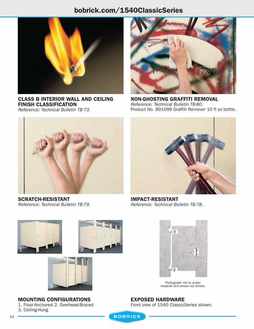
MOUNTING CONFIGURATIONS1. Floor-Anchored 2. Overhead-Braced 3. Floor-To-Ceiling 4. Ceiling-Hung
10
bobrick.com/1080-1180DuraLineSeries
SCRATCH- AND IMPACT-RESISTANTReferences: Technical Bulletin TB-78 and TB-79.
CLASS A OR B INTERIOR WALL ANDCEILING FINISH CLASSIFICATIONReference: Technical Bulletin TB-73.
MOISTURE-RESISTANTWithstands hose-down maintenance andenvironmental moisture.
NON-GHOSTING GRAFFITI REMOVALReference: Technical Bulletin TB-80.Product No. 891099 Graffiti Remover 10 fl oz bottle.
TOILET PARTITION PRIVACY OPTIONS1. Gap-Free interlocking design, no sight lines.2. Maximum-Height: 72" doors/panels, 4 ≤" floor
clearance. See page 2.
22081 Series, Floor-Anchoredmounting configuration shown.
Plan view of Gap-Free door-stile interlocks, not to scale.
Front views of Gap-Freepartition doors, openand closed.
1
10048_08:TP2008 10/13/09 6:39 PM Page 10
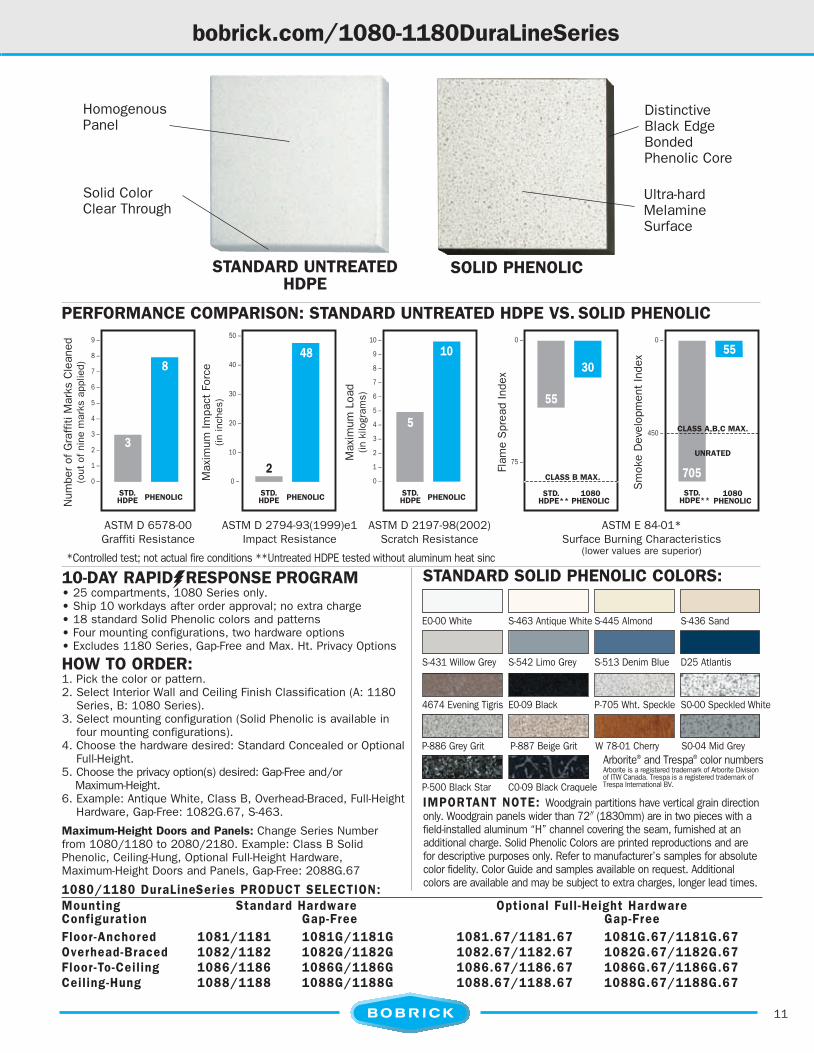
11
bobrick.com/1080-1180DuraLineSeries
PERFORMANCE COMPARISON: STANDARD UNTREATED HDPE VS. SOLID PHENOLIC
30
5
10
2
48
3
8
55
55
705
PHENOLICPHENOLIC PHENOLIC 1080PHENOLIC
1080 PHENOLIC
0 –
75 –
0 –
450 –
10 –
9 –
8 –
7 –
6 –
5 –
4 –
3 –
2 –
1 –
0 –
50 –
40 –
30 –
20 –
10 –
0 –
9 –
8 –
7 –
6 –
5 –
4 –
3 –
2 –
1 –
0 –
CLASS A,B,C MAX.
UNRATED
CLASS B MAX.
STD. HDPE
STD. HDPE
STD. HDPE
STD. HDPE**
STD. HDPE**
A
ASTM D 6578-00Graffiti Resistance
ASTM D 2794-93(1999)e1Impact Resistance
ASTM D 2197-98(2002) Scratch Resistance
ASTM E 84-01*Surface Burning Characteristics
(lower values are superior)
Num
ber
ofG
raff
itiM
arks
Cle
aned
(out
ofni
nem
arks
appl
ied)
Max
imum
Impa
ctFo
rce
(inin
ches
)
Max
imum
Load
(inki
logr
ams)
Flam
eS
prea
dIn
dex
Sm
oke
Dev
elop
men
tIn
dex
SOLID PHENOLIC
DistinctiveBlack EdgeBondedPhenolic Core
Ultra-hardMelamineSurface
STANDARD UNTREATEDHDPE
Solid ColorClear Through
HomogenousPanel
1080/1180 DuraLineSeries PRODUCT SELECTION:Mounting Standard Hardware Optional Full -Height HardwareConfiguration Gap-Free Gap-FreeFloor-Anchored 1081/1181 1081G/1181G 1081.67/1181.67 1081G.67/1181G.67Overhead-Braced 1082/1182 1082G/1182G 1082.67/1182.67 1082G.67/1182G.67Floor-To-Ceil ing 1086/1186 1086G/1186G 1086.67/1186.67 1086G.67/1186G.67Ceil ing-Hung 1088/1188 1088G/1188G 1088.67/1188.67 1088G.67/1188G.67
10-DAY RAPIDƒRESPONSE PROGRAM• 25 compartments, 1080 Series only.• Ship 10 workdays after order approval; no extra charge• 18 standard Solid Phenolic colors and patterns• Four mounting configurations, two hardware options• Excludes 1180 Series, Gap-Free and Max. Ht. Privacy Options
STANDARD SOLID PHENOLIC COLORS:*Controlled test; not actual fire conditions **Untreated HDPE tested without aluminum heat sinc
E0-00 White S-463 Antique White S-445 Almond S-436 Sand
S-431 Willow Grey S-542 Limo Grey S-513 Denim Blue D25 Atlantis
4674 Evening Tigris E0-09 Black P-705 Wht. Speckle S0-00 Speckled White
P-886 Grey Grit P-887 Beige Grit W 78-01 Cherry S0-04 Mid Grey
P-500 Black Star C0-09 Black Craquele
Arborite® and Trespa® color numbersArborite is a registered trademark of Arborite Divisionof ITW Canada. Trespa is a registered trademark ofTrespa International BV.
HOW TO ORDER:1. Pick the color or pattern.2. Select Interior Wall and Ceiling Finish Classification (A: 1180
Series, B: 1080 Series).3. Select mounting configuration (Solid Phenolic is available in
four mounting configurations).4. Choose the hardware desired: Standard Concealed or Optional
Full-Height.5. Choose the privacy option(s) desired: Gap-Free and/or
Maximum-Height.6. Example: Antique White, Class B, Overhead-Braced, Full-Height
Hardware, Gap-Free: 1082G.67, S-463.IMPORTANT NOTE: Woodgrain partitions have vertical grain directiononly. Woodgrain panels wider than 72" (1830mm) are in two pieces with afield-installed aluminum “H” channel covering the seam, furnished at anadditional charge. Solid Phenolic Colors are printed reproductions and arefor descriptive purposes only. Refer to manufacturer’s samples for absolutecolor fidelity. Color Guide and samples available on request. Additionalcolors are available and may be subject to extra charges, longer lead times.
Maximum-Height Doors and Panels: Change Series Numberfrom 1080/1180 to 2080/2180. Example: Class B SolidPhenolic, Ceiling-Hung, Optional Full-Height Hardware,Maximum-Height Doors and Panels, Gap-Free: 2088G.67
10048_08:TP2008 10/13/09 6:39 PM Page 11
12
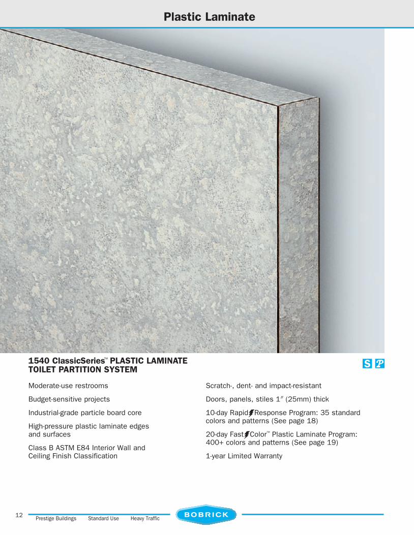
Plastic Laminate
Prestige Buildings Standard Use Heavy Traffic
1540 ClassicSeries™ PLASTIC LAMINATETOILET PARTITION SYSTEM
Moderate-use restrooms
Budget-sensitive projects
Industrial-grade particle board core
High-pressure plastic laminate edgesand surfaces
Class B ASTM E84 Interior Wall andCeiling Finish Classification
Scratch-, dent- and impact-resistant
Doors, panels, stiles 1" (25mm) thick
10-day RapidƒResponse Program: 35 standardcolors and patterns (See page 18)
20-day FastƒColor™ Plastic Laminate Program:400+ colors and patterns (See page 19)
1-year Limited Warranty
10048_08:TP2008 10/13/09 6:39 PM Page 12

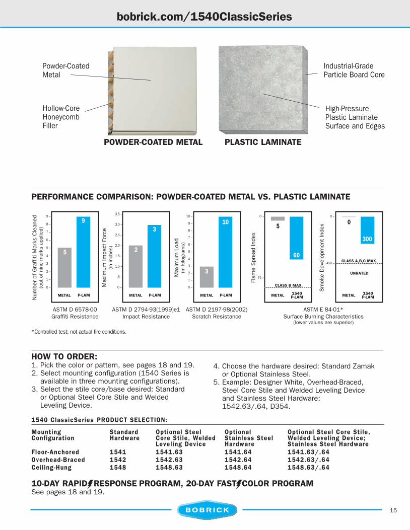
STANDARD FLOOR-ANCHORED STILEBASE, LEVELING DEVICE3⁄8" (10mm) thick plated steel leveling bar factory-installed to stile. Furnished with 3⁄8" (10mm)diameter stainless steel wedge floor anchors.
OPTIONAL STEEL-CORE STILE ANDWELDED LEVELING DEVICE11-gauge steel stile core welded to 3⁄8" (10mm) thickplated steel leveling bar forms single structural unit.Add suffix .63 to 1540 Series Number.
STANDARD OVERHEAD-BRACED STILEBASE, LEVELING DEVICE12-gauge plated steel brackets attached to bottomof stile. Furnished with leveling bolt, floor “L”brackets, screws, plastic anchors.
OPTIONAL THROUGH-BOLTED STAINLESSSTEEL HARDWAREHeavy-duty, cast type 304 stainless steel hinges,clothes hook, emergency access door keeper.Stainless steel mounting brackets and shoe. Addsuffix .64 to 1540 Series Number.
STANDARD THROUGH-BOLTED ZAMAKHARDWAREHinges, latch, keeper, coat hook, mounting hardwareare polished chrome-plated Zamak. For emergencyaccess door lifts from outside. Patented one-piecestainless steel shoe conceals stile leveling device.
13
Zamak and Heavy-Duty Stainless Steel Hardware
DESIGNER’S NOTE:Classic, Designer and TrimLine Series are notrecommended for heavy traffic and vandal-pronerestrooms, moisture-prone spaces or hose-downmaintenance. SierraSeries and DuraLineSeriestoilet partitions are recommended for theserestroom conditions.
10048_08:TP2008 10/13/09 6:39 PM Page 13
MOUNTING CONFIGURATIONS1. Floor-Anchored 2. Overhead-Braced3. Ceiling-Hung
14
bobrick.com/1540ClassicSeries
NON-GHOSTING GRAFFITI REMOVALReference: Technical Bulletin TB-80.Product No. 891099 Graffiti Remover 10 fl oz bottle.
CLASS B INTERIOR WALL AND CEILINGFINISH CLASSIFICATIONReference: Technical Bulletin TB-73.
1 2
3
EXPOSED HARDWAREFront view of 1540 ClassicSeries shown.
IMPACT-RESISTANTReference: Technical Bulletin TB-78.
SCRATCH-RESISTANTReference: Technical Bulletin TB-79.
Photograph not to scale;headrail and shoes not shown.
10048_08:TP2008 10/13/09 6:39 PM Page 14
15
510
3
3
2
9
5 60
0
300
METALMETAL P-LAM P-LAM P-LAM 1540P-LAM
1540 P-LAMMETAL METAL METAL
0 –
75 –
0 –
450 –
10 –
9 –
8 –
7 –
6 –
5 –
4 –
3 –
2 –
1 –
0 –
3.5 –
3.0 –
2.5 –
2.0 –
1.5 –
1.0 –
.5 –
0 –
9 –
8 –
7 –
6 –
5 –
4 –
3 –
2 –
1 –
0 –
CLASS A,B,C MAX.
UNRATED
CLASS B MAX.
ASTM D 6578-00Graffiti Resistance
ASTM D 2794-93(1999)e1Impact Resistance
ASTM D 2197-98(2002) Scratch Resistance
ASTM E 84-01*Surface Burning Characteristics
(lower values are superior)
Num
ber
ofG
raff
itiM
arks
Cle
aned
(out
ofni
nem
arks
appl
ied)
Max
imum
Impa
ctFo
rce
(inin
ches
)
Max
imum
Load
(inki
logr
ams)
Flam
eS
prea
dIn
dex
Sm
oke
Dev
elop
men
tIn
dex
bobrick.com/1540ClassicSeries
HOW TO ORDER:1. Pick the color or pattern, see pages 18 and 19.2. Select mounting configuration (1540 Series is
available in three mounting configurations).3. Select the stile core/base desired: Standard
or Optional Steel Core Stile and WeldedLeveling Device.
PERFORMANCE COMPARISON: POWDER-COATED METAL VS. PLASTIC LAMINATE
PLASTIC LAMINATE
Industrial-GradeParticle Board Core
High-PressurePlastic LaminateSurface and Edges
POWDER-COATED METAL
Hollow-CoreHoneycombFiller
Powder-CoatedMetal
*Controlled test; not actual fire conditions.
1540 ClassicSeries PRODUCT SELECTION:
Mounting Standard Optional Steel Optional Optional Steel Core Stile,Configuration Hardware Core Stile, Welded Stainless Steel Welded Leveling Device;
Leveling Device Hardware Stainless Steel HardwareFloor-Anchored 1541 1541.63 1541.64 1541.63/.64Overhead-Braced 1542 1542.63 1542.64 1542.63/.64Ceil ing-Hung 1548 1548.63 1548.64 1548.63/.64
10-DAY RAPIDƒRESPONSE PROGRAM, 20-DAY FASTƒCOLOR PROGRAMSee pages 18 and 19.
4. Choose the hardware desired: Standard Zamakor Optional Stainless Steel.
5. Example: Designer White, Overhead-Braced,Steel Core Stile and Welded Leveling Deviceand Stainless Steel Hardware:1542.63/.64, D354.
10048_08:TP2008 10/13/09 6:39 PM Page 15

OPTIONAL FULL-HEIGHT STAINLESSSTEEL HARDWARESelf-closing hinge, brackets, U-channels, door stops,latch and keeper; clothes hook. Add suffix .65.
16
bobrick.com/1040DesignerSeries .../1030TrimLineSeries
STANDARD CONCEALED STAINLESSSTEEL HARDWARETwo satin-finish adjustable barrel hinges, slide latchwith keeper, clothes hook; emergency access.
1040 DesignerSeries™
.050" (1mm) thick plastic laminate edges andsurfaces.
STANDARD STEEL-CORE STILE ANDWELDED LEVELING DEVICESteel-core stile welded to steel leveling bar.
1030 TrimLineSeries™
Satin-finish stainless steel edge trim routed flushwith plastic laminate surfaces.
THREADED INSERTS, T-NUTSFactory installed. Provide metal-to-metal contact for
securing door hinges and latch track.
10048_08:TP2008 10/13/09 6:40 PM Page 16

17
bobrick.com/1040DesignerSeries .../1030TrimLineSeries
HOW TO ORDER 1040 SERIES:1. Pick the color or pattern, see pages 18 and 19.2. Select mounting configuration (1040 Series is
available in three mounting configurations: Floor-Anchored, Overhead-Braced, Ceiling-Hung).
3. Choose the hardware desired: StandardConcealed or Optional Full-Height.
4. Example: Grey Glace, Floor-Anchored, Full-HeightHardware: 1041.65, 4142.
HOW TO ORDER 1030 SERIES:1. Pick the color or pattern, see pages 18 and 19.2. Select mounting configuration (1030 Series is
available in three mounting configurations: Floor-Anchored, Overhead-Braced, Ceiling-Hung).
3. Choose the hardware desired: StandardConcealed or Optional Full-Height.
4. Example: Tungsten EV, Overhead-Braced, Full-Height Hardware: 1032.65, 4814.
1040 DesignerSeries PRODUCT SELECTION:
Mounting Standard Optional Full-Configuration Hardware Height HardwareFloor-Anchored 1041 1041.65Overhead-Braced 1042 1042.65Ceil ing-Hung 1048 1048.65
1030 TrimLineSeries PRODUCT SELECTION:
Mounting Standard Optional Full-Configuration Hardware Height HardwareFloor-Anchored 1031 1031.65Overhead-Braced 1032 1032.65Ceil ing-Hung 1038 1038.65
10-DAY RAPIDƒRESPONSE PROGRAM, 20-DAY FASTƒCOLOR PROGRAMSee pages 18 and 19.
FRONT VIEW1040 Designer (shown) and 1030 TrimLine Series.
DESIGNER’S NOTE 1040 SERIES:Per ASTM E84 tests:Flame-spread index – 60Smoke-developed index – 195Meets Class B ASTM E84 Interior Wall
and Ceiling Finish ClassificationSee Bobrick Advisory Bulletin TB-73
DESIGNER’S NOTE 1030 SERIES:Per ASTM E84 tests:Flame-spread index – 60Smoke-developed index – 265Meets Class B ASTM E84 Interior Wall
and Ceiling Finish ClassificationSee Bobrick Advisory Bulletin TB-73
Photographs not to scale;headrail and shoes not shown.
INSIDE VIEW1040 Designer (shown) and 1030 TrimLine Series.
CONCEALED HARDWARE
10048_08:TP2008 10/13/09 6:40 PM Page 17

18
bobrick.com/DividersScreens
HOW TO ORDER:1. Pick the color or pattern, see pages 7, 11, 18 and 19. 2. Select the product (Shower Divider, Dressing Compartment,Urinal Screen). 3. Choose the Series (Classic, Designer,TrimLine, DuraLine, Sierra). 4. Select the mountingconfiguration. 5. Example: Brittany Blue, Urinal Screen, ClassicSeries, Wall-Hung: 1545, D321.
OVERHEAD-BRACED SHOWER DIVIDERS Shower curtain trackand hooks in headrail.
WALL-HUNG, FLOOR-ANCHORED, POST-TO-CEILING SCREENS
SHOWER DIVIDERS, DRESSING COMPARTMENTS, AND URINAL SCREENS PRODUCT SELECTION:
Series Shower Dividers Dress.Comp. Urinal Screen ConfigurationsOverhead-Braced Overhead-Braced Floor-Anchored Post-to-Ceil ing Wall -Hung Ceil ing-Hung
ClassicSeries NR 1542 1541 N/A 1545 1548DesignerSeries NR 1042 1041 1043 1045 1048TrimLineSeries NR 1032 1031 1033 1035 1038DuraLineSeries 1082/1182 1082/1182 1081/1181 1083/1183 1085/1185 1088/1188SierraSeries 1092 1092 N/A 1093 1095 N/A
NR: Not recommended for wet areas. N/A: Not available.
Coordinate urinal, entrance screens, shower dividers and dressingcompart ments with toilet partitions. Select 1092 or 1080/1180shower dividers and dressing com partments for wet-areas. Overhead-braced configuration can be furnished with shower curtains, curtaintrack and hooks concealed in headrail.
SHOWER DIVIDERS, DRESSING COMPARTMENTS, URINAL SCREENS
bobrick.com/PlasticLaminateColors
IMPORTANT NOTE: Woodgrain partitions have vertical graindirection only. Woodgrain panels wider than 60" (1525mm) will bespliced, joining the two pieces onto the particle board core for anadditional charge. Plastic Laminate Colors above are printedreproductions and are for descriptive purposes only. Refer tomanufacturer’s samples for absolute color fidelity. Color Guide andsamples are available from Bobrick on request. Additional colors areavailable and may be subject to extra charges and longer lead times.
10-DAY RAPIDƒRESPONSE® TOILET PARTITION ORDER FULFILLMENT PROGRAM Series Max. No. Cmpts. Colors Mounting Ready For Shipment1540 25 35 *1030 25 35 *1040 25 35 *1080 25 18 All1090 25 4 **
*Ceiling-Hung, Floor-Anchored and Overhead-Braced; not available in Floor-To-Ceiling. **0verhead-Braced, Floor-To-Ceiling and Ceiling-Hung; not available in Floor-Anchored. 1180 Series, Gap-Free and Maximum-Height Privacy Options not available with RapidƒResponse.
10 WorkdaysAfter Order
Approval
D354 Des. Wht 1573 Frosty Wht 1500 Grey D315 Platinum 4674 Eve Tigris D91 Slate Grey 1572 Antq. White D30 Nat. Almond
1530 Beige D97 Haze D50 Khaki Brn 4841 Des Zphyr D96 Shadow D14 Port D321 Brit. Blue D25 Atlantis
1595 Black 4621 Wht. Neb. 4142 Grey Glace 4622 Grey Neb. 4623 Grpht. Neb. 4794 Wndspt Brz 4608 Cald. Beige 4143 Neut. Glace
4814 Tungsten EV 4669 Nat. Tigris 4738 Ochre Rolet. 1787 Oxide 7054 Wld Cherry 7040A Fig. Mhgny 4624 Beige Neb. 4632 Teal Neb.
4630 Cloud Neb. 4759 Mystq. Mrn. 4552 Ebony Star
STANDARD PLASTIC LAMINATE COLORS AND PATTERNS: All Wilsonart® color numbers
10048_08:TP2008 10/13/09 6:40 PM Page 18

NUMBER OF COLORS AND PATTERNS BY MANUFACTURER:Wilsonart: 171 Formica: 129 Nevamar: 120
Color submittals download from: • www.wilsonart.com • www.formica.com • www.nevamar.comBOBRICK'S iBOB ORDER ENTRY SYSTEM ON BOBRICK.COM:• Instant confirmation of color or pattern availability.• Immediate electronic job quotation to distributor.
D E C O R AT I V E S U R FAC E S
bobrick.com/FastColorProgram
19
NEW! 20-DAY FASTƒ COLOR™ 400+ PLASTIC LAMINATE TOILET PARTITION PROGRAM
20-DAY FASTƒCOLOR PROGRAM
• 15 compartments• Ship 20 workdays after order approval• 400+ Wilsonart, Formica, Nevamar standard,
stocked colors• Three mounting configurations (Ceiling-Hung, Floor-Anchored,
Overhead-Braced)• Two hardware options• Three Series (1540, 1040, 1030; there is a longer lead
time for 1030 Series in Canada) Wilsonart, Formica and Nevamar are registered trademarks of Wilsonart International, Formica Corporation and Panolam Industries respectively
1595 Black 4621 Wht. Neb. 4142 Grey Glace 4622 Grey Neb. 4623 Grpht. Neb. 4794 Wndspt Brz 4608 Cald. Beige 4143 Neut. Glace
10048_08:TP2008 10/13/09 6:40 PM Page 19

BOBRICK.COM
COMPANY DIRECTORY:
Los Angeles: 11611 Hart Street North Hollywood, California 91605-5882 Washroom Accessories: (818) 982-9600, FAX: (818) 503-1102 e-mail: [email protected] Toilet Partitions: (818) 982-9070; FAX: (818) 503-9287 e-mail: [email protected]
Jackson, TN: 100 Bobrick DriveJackson, TN 38301-5625 Washroom Accessories: (731) 424-7000, FAX: (731) 424-7800 e-mail: [email protected] Partitions: (731) 424-7000, FAX: (731) 265-0578
New York: 200 Commerce DriveClifton Park, NY 12065-1350 (518) 877-7444; FAX: (518) 877-5029e-mail: [email protected]
Canada: Bobrick Washroom Equipment Company45 Rolark Drive, Scarborough, Ontario M1R 3B1(416) 298-1611; FAX: (416) 298-6351 e-mail: [email protected]
International Sales: 11611 Hart Street North Hollywood, California 91605-5882(818) 764-1000; FAX: (818) 503-9941e-mail: [email protected]
Australia: Bobrick Washroom Equipment Pty. Ltd. +1 (818) 764-1000; FAX: +1 (818) 503-9941e-mail: [email protected]
Germany: Bobrick Washroom Equipment +1 (818) 764-1000; FAX: +1 (818) 503-9941e-mail: [email protected]
United Kingdom: Bobrick Washroom Equipment Ltd.+44 (0)20 8366 1771; FAX: +44 (0)20 8363 5794e-mail: [email protected]
Bobrick products are protected under one or more of the followingPatent Numbers. Canada: 2196729; United States: 7520022,7032351, 6443411, 5660011. Other patents pending.See Bobrick's Washroom Accessories Catalog to find products that meet the occupancy needs of a variety of building types.
BOBRICK PRODUCT WARRANTIES AND LIMITATIONS:
Product WarrantiesThe following Bobrick toilet partition panels, doors and stiles arewarranted against breakage, corrosion, delamination and defects inworkmanship from the date of purchase for the periods set forth below (this limited warranty is conditioned on the toilet partitionsbeing properly installed, used and serviced):
Toilet Partitions Limited WarrantySierraSeries, 1090 10 yearsDuraLineSeries, 1080/1180 15 yearsToilet Partition Series not otherwise listed 1 year(i.e., TrimLine, Designer, ClassicSeries)
Hardware for all series of Bobrick toilet partitions is warranted to befree from defects in workmanship and material under normal usageservice for one year from the date of purchase. (Rust and discolorationto stainless steel parts resulting from exposure to harsh environmentaland/or chemical conditions are not considered to be defects inworkmanship or material and there is no expressed or implied warrantyprovided for such condition. Refer to Bobrick Advisory Bulletin TB-21,Effective Ways to Clean Stainless Steel.)
Limitations on WarrantiesIn all instances, the purchaser’s exclusive remedy against Bobrickis for the repair or replacement, at Bobrick’s option, of warranteddefective products or parts. Bobrick will also bear the cost of thepurchaser’s return of defective products or parts to Bobrick. Bobrick’swarranties set forth above do not cover damage resulting fromvandalism. No other remedy (including, but not limited to, damagesfor field labor charges, lost profits, lost sales, injury to persons orproperty or any other incidental or consequential losses) is available.
Compare Solid Color Reinforced Composite (SCRC) with solidplastic. Telephone (800) 553-1600 or visit www.bobrick.comfor a complimentary test kit.
Bobrick’s North American network of manufacturing, customerservice and distribution facilities provides responsive customersupport from four strategic locations.
ORDER YOUR TEST KIT TODAYNEAR TO YOU
ClassicSeries, DesignerSeries, MatrixSeries, FastColor, TrimLineSeries are each trademarks; ConturaSeries, RapidResponse, SierraSeries, DuraLineSeries, GraffitiOffare each registered trademarks of Bobrick Washroom Equipment, Inc. Illustrations and descriptions herein are applicable to production as of the date of this catalog.The manufacturer reserves the right and does from time to time make changes and improvements in designs and dimensions. Catalog No. TP-0907, 150M. October 31, 2009. © 2009 Bobrick Washroom Equipment, Inc. Printed in U.S.A.
10048_08:TP2008 10/13/09 6:40 PM Page 20

20 feet620cm
601525
601525
601525
Baby changing station19 x 33 inches (485 x 840mm) in down position
Urinal with elongated bowel
10 feet - 7 inches323cm
14 feet - 8 inches446cm
60 min1525
Wheelchairturning space
56 x 60 min1420 x 1525Wheelchair accessible toilet compartment withwall-mounted toilet
56 x 60 min1420 x 1525Wheelchair accessible toilet compartment withwall-mounted toilet
30 x 48760 x 1220Clear floor spaceat lavatory
60 min1525
Wheelchairturning space
30 x 48760 x 1220Clear floor spaceat urinal
30 x 48760 x 1220Clear floor space
Vertical grab bars 18 inches (455mm) long (ICC/ANSI)
RefeRencing:
2010 ADA StAnDARDS foR AcceSSible DeSign
icc A117.1 -2009 – AcceSSible AnD USAble bUilDingS AnD fAcilitieS
Planning guide for accessible restrooms
481220
2
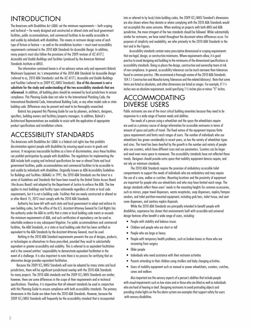
intRoDUction The Americans with Disabilities Act (ADA) set the minimum requirements – both scoping and technical – for newly designed and constructed or altered state and local government facilities, public accommodations, and commercial facilities to be readily accessible to and usable by individuals with disabilities. This means in restroom design some of each type of fixture or feature – as well as the installation location – must meet accessibility requirements contained in the 2010 ADA Standards for Accessible Design. In addition, many projects must also follow the provisions of the 2009 revision of ICC A117.1, Accessible and Usable Buildings and Facilities (produced by the American National Standards Institute or ANSI). The information contained herein is of an advisory nature only and represents Bobrick Washroom Equipment, Inc.’s interpretation of the 2010 ADA Standards for Accessible Design (referred to as, 2010 ADA Standards) and the ICC A117.1, Accessible and Usable Buildings and Facilities (referred to as 2009 ICC/ANSI Standards). Use of this document is not a substitute for the study and understanding of the two accessibility standards that are referenced. In addition, all building plans should be reviewed by local jurisdictions to ensure compliance. This Planning Guide does not refer to the International Plumbing Code, the International Residential Code, International Building Code, or any other model code or state building code. Differences may be present and need to be thoroughly researched. Bobrick has prepared this Planning Guide for use by planners, architects, designers, specifiers, building owners and facilities/property managers. In addition, Bobrick’s Architectural Representatives are available to assist with the application of appropriate product specifications and installation criteria.
AcceSSibilitY StAnDARDSThe Americans with Disabilities Act (ADA) is a federal civil rights law that prohibits discrimination against people with disabilities by ensuring equal access to goods and services. It recognizes inaccessible facilities as a form of discrimination, since these facilities can prohibit participation by people with disabilities. The regulations for implementing the ADA include both scoping and technical specifications for new or altered State and local government facilities, public accommodations and commercial facilities to be accessible to and usable by individuals with disabilities. Originally known as ADA Accessibility Guidelines for Buildings and Facilities (ADAAG) in 1991, the 2010 ADA Standards are the latest in a series of Guidelines and Standards that have been issued by the United States Access Board (the Access Board) and adopted by the Department of Justice to enforce the ADA. The law applies to most buildings and facility types nationwide regardless of state or local code requirements, but it is not a building code. Facilities that are newly constructed or altered on or after March 15, 2012 must comply with the 2010 ADA Standards. Authority has been left with each state and local government to adopt and enforce its own building codes, but the office of the U.S. Assistant Attorney General for Civil Rights has the authority under the ADA to certify that a state or local building code meets or exceeds the minimum requirements of ADA, and such certification of equivalency can be used as rebuttable evidence in any subsequent litigation. For public accommodations and commercial facilities, the ADA Standards, or a state or local building code that has been certified as equivalent to the ADA Standards by the Assistant Attorney General, must be used. Nothing in the 2010 ADA Standard requirements prevents the use of designs, products, or technologies as alternatives to those prescribed, provided they result in substantially equivalent or greater accessibility and usability. This is referred to as equivalent facilitation and is the covered entities’ responsibility to demonstrate equivalent facilitation in the event of a challenge. It is also important to note there is no process for certifying that an alternative design provides equivalent facilitation. Because the 2009 ICC/ANSI Standards will soon be adopted by many states and local jurisdictions, there will be significant jurisdictional overlap with the 2010 ADA Standards for many projects. The 2010 ADA standards and the 2009 ICC/ANSI Standards are similar; however, there are some differences in the scope of their requirements and in technical specifications. Therefore, it is imperative that all relevant standards be used in conjunction with this Planning Guide to ensure compliance with both accessibility standards. The primary dimensions in this Guide are taken from the 2010 ADA Standards. However, because the 2009 ICC/ANSI Standards will frequently be the accessibility standard that is incorporated
into or referred to by local/state building codes, the 2009 ICC/ANSI Standard’s dimensions are also shown where they deviate or where complying with the 2010 ADA Standards would not accomplish the same outcome. When working on projects with both ANSI and ADA jurisdiction, the more stringent of the two standards should be followed. While substantially similar for restrooms, we have noted throughout the document where differences occur. For purposes of simplicity and readability, we refer primarily to the 2010 ADA Standards in the text and in the Figures. Accessibility standards contain many prescriptive dimensional or scoping requirements that are legal, design, or construction minimums. Where requirements allow, it is good practice to avoid designing and building to the minimums of the dimensional specifications in accessibility standards. Doing so places the design, construction and ownership team at risk of non-compliance. In general, accessibility tolerances can be much narrower than tolerances found in common practice. (We recommend a thorough review of the 2010 ADA Standards: 104.1.1 Construction and Manufacturing Tolerances and the related Advisory). Note that some items are listed as absolutes, and other dimensions are listed as ranges. For example, if 1-½ inches was an absolute requirement, avoid specifying 1-½ inches plus or minus “X” inches.
AccoMMoDAting DiVeRSe USeRS Public restrooms are one of the most critical building amenities because they need to be responsive to a wide range of human needs and abilities. The needs of a person using a wheelchair and the space the wheelchairs require are used as a primary source of design information for accessible restrooms in terms of amount of space and paths of travel. The fixed nature of the equipment imposes finite space requirements and limits reach ranges of users. The number of individuals who use wheelchairs has grown considerably in recent years, as has the variety of wheelchair types and sizes. The trend has been dwarfed by the growth in the number and variety of people who use scooters, which have different sizes and use parameters. Scooters can be larger and need even more space to maneuver. The accessibility standards have not reflected these trends. Designers should provide extra space that mobility equipment devices require, and not rely on minimum standards. The 2010 ADA Standards require the provision of ambulatory accessible toilet compartments to support the needs of individuals who are ambulatory and may require the use of a cane, walker or crutches. Mounting locations and the proximity of equipment are important for people who use wheelchairs and who may have limited reach range. The design standards reflect these users’ needs in the mounting heights for common accessories, such as mirrors, paper towel dispensers, waste receptacles, soap dispensers, napkin/tampon vendors, and toilet partition-mounted equipment, including grab bars, toilet tissue, and seat-cover dispensers, and sanitary napkin disposals. While the 2010 ADA Standards are principally intended to benefit people with disabilities, experience has shown that environments built with accessible and universal design features often benefit a wide range of users, including:
• Peoplewithstabilityandbalanceissues
• Childrenandpeoplewhoareshortortall
• Peoplewhoarelargeorheavy
• Peoplewithtemporaryhealthproblems,suchasbrokenbonesorthosewhoarerecovering from surgery
• Olderpeople
• Individualswhoneedassistancewiththeirrestroomactivities
• Parentsattendingtotheirchildrenusingstrollersandbabychangingactivities.
• Usersofmobilityequipmentsuchasmanualorpowerwheelchairs,scooters,crutches,canes and walkers
Also important are the sensory aspects of a person’s abilities that include people with visual impairments such as low vision and or those who are blind as well as individuals who are hard of hearing or deaf. Designing restrooms to avoid protruding objects and providing strobe lights on the fire alarm system are examples that support safety for users with sensory disabilities.

3
Often overlooked in these considerations are the family, companions, or caregivers who may accompany an individual who expects and relies on accessibility features in restrooms. One trend that recognizes the need for assistance for many restroom users is the increased presence of family restrooms. These restrooms will accommodate diaper changing and children and older individuals who need assistance, particularly from opposite gender caregivers.
SPAce ReQUiReMentS AnD ReAcH RAngeSThe STandardS deSignaTe Clear Floor SpaCe to accommodate a single wheelchair of at least 30 inches by 48 inches (760 by 1220mm). The space can be positioned for a forward or parallel approach to restroom elements. A portion of the clear floor space may be located under fixtures, lavatories, or accessories as long as the required knee and toe clearance is provided (Fig. 14 and many others). If properly centered in front of controls and operating mechanisms, the clear floor space will allow both left- and right-hand access.
reaCh rangeS and MoUnTing heighTS for restroom accessories may vary within a facility depending on the location of individual accessories and the direction of reach required for their use. To allow use by people with limited reach range, it is required that accessories be mounted with their “operable parts” – dispensing mechanisms, start buttons, coin slots, or dispenser openings – located no more than 48 inches (1220mm) above the finish floor (Fig. 1a.). Where accessories are mounted over obstructions such as counters, depending on the nature and depth of the obstruction it is required that they be located between 44 inches and 48 inches (1120 and 1220mm) maximum above the finish floor. The operable portions of any accessory should be mounted no lower than 15 inches (380mm) above the floor. However, the 2009 ICC/ANSI Standards limit the operable portions of dispensers in toilet compartments to no lower than 18 inches (455mm). When determining the mounting location of restroom accessories, make sure to account for side and forward approaches.
The 2009 ICC/ANSI Standards require that soap dispenser controls, and faucets, that serve certain accessible lavatories need to be installed with a reach depth of 11 inches (280mm) maximum. The need for enhanced reach ranges is, determined by scoping requirements. The 2009 ICC/ANSI Standards require altered installation heights and locations for towel dispensers and hand dryers where reaching is obstructed, such as units mounted on perpendicular walls adjacent to accessible lavatories. The operable portions of these elements may need to be installed as low as 34 inches (865mm) as shown in the table below, depending on how far back from the front edge of a lavatory or counter a unit is mounted.
obSTrUCTed reaCh
TUrning SpaCeS in reSTrooMS may be either a 60 inch (1525mm) circular space or a T-Shaped turning space within a 60 inch (1525mm) square minimum with arms and base minimum 36 inches (915mm) wide. The circular space allows a person using a wheelchair to make a 180-degree or 360 degrees turn (Fig. 2a). The T-Shaped space allows for a three-point-turn (Fig. 2b) and may be used to conserve space in some installations. A portion of the 60 inches (1525mm) diameter or T-Shaped turning spaces may be located under fixtures, lavatories, or accessories as long as the required knee and toe clearance is provided.
MaxiMuM Reach DePTh
0.5 inches (13mm)
2 inches (51mm)
5 inches (125mm)
6 inches (150mm)
9 inches (230mm)
11 inches (280mm)
MaxiMuM Reach heiGhT
48 inches (1220mm)
46 inches (1170mm)
42 inches (1065mm)
40 inches (1015mm)
36 inches (915mm)
34 inches (865mm)
Fig. 1b Mirror and Toilet Grab Bar Mounting heights.
33-36840-915
Fig. 1 Mounting heights for Restroom accessories.
Fig. 1a upper Range of Mounting heights for Restroom accessories with Operable Parts.
44-481120-1220 If mounted over counter or lavatory,
40 inches max (1015mm) to bottom of reflective surface35 inches max (890mm) if not mounted over counter or lavatory
C: 18-27455-685Depending on age
C: 36-44915-1120Depending on age
Fig. 2 Wheelchair Turning Spaces.
Fig. 2a 60 inch (1525mm) Diameter Turning Space.
60 min1525
60 min1525
Fig. 2b T-Shaped Turning Space.
12 min305
60 min1525
12 min30536 min
915
36 min915
24 min610
noTeS For all FigUreS in ThiS planning gUide1. This edition of the Planning Guide for Accessible Restrooms has adopted the simple measurement notation
for figures that is found in the current standards. This notation eliminates the use of English and metric notation, substituting inch and millimeter dimensions with the inch always appearing over the millimeter in this manner:
2. In certain figures with whole restrooms, overall room dimensions are given in feet and inches with the metric dimension listed in centimeters (cm).
3. Bobrick product references are provided for many restroom layout fixtures. Not all figures and standards’ references have a corresponding Bobrick product.
4. Neither standard requires that grab bars be located with reference to the center of the escutcheon. This Planning Guide shows centerline dimension lines where appropriate for locating grab bars. Both standards locate horizontal grab bars from finish floor to top of gripping surface.
481220

4
cHilDRen’S ReAcH RAngeSRefer to these tables to find the dimensions when designing restrooms primarily for children’s use. Select the dimensions that are most appropriate for the specific children’s age group for which you are designing. Mounting heights for children vary depending on age. The age groups are 3 and 4, 5 through 8 and 9 through 12 years.
Children’S reaCh rangeS
diMenSionS aT WaTer CloSeTS Serving Children ageS 3 ThroUgh 12
the blue notations beginning with “c:” in many of the figures that follow in this Planning guide refer to children’s measurements.
UniVeRSAl DeSignThe accessibility standards are often described as minimums and contain numerous minimum requirements. These minimum requirements are often usability minimums as well, with requirements below which many cannot operate easily, safely or at all. In spite of this, nationwide accessibility mandates have created the widespread expectation for more usable environments. In the interests of an even wider reach for more accommodating designs, and to extend those designs beyond accessibility minimums, the concept of universal design arose. A universal approach includes improved usability characteristics and/or options in all products, building elements, and spaces to ensure that they are usable to the greatest extent possible by people of all ages and abilities. A universal approach will also produce improved usability features that are integrated with the overall design of a facility, even if a particular element or feature clearly has a more limited target group. To provide diverse examples, this Planning Guide displays designs that conform to minimums and those that exceed minimums, achieving more universal results.
UniverSal deSign can be accomplished in some instances by simply using the same item for everyone; sometimes by positioning an item differently; at other times by modifying or replacing a single manufactured feature of an item; and in some circumstances by replacing an item with one that is more adjustable or adaptable. In most cases a universal approach mainstreams universal features by eliminating radically different looking items and the stigma associated with them while providing choices for all users.
leFT- and righT-hand USe oF FiXTUreS Some people with disabilities can only use certain features of fixtures and accessories if they can approach them from the left or right side. This limitation affects the usability of toilet and shower compartments and restroom accessories that are not symmetrical. Both the 2010 ADA and the 2009 ICC/ANSI Standards require both left- and right-handed facilities be available in restrooms. The concept of universal design suggests that when restrooms are planned, both left- and right-handed versions should be provided to the greatest extent possible (see Clear Floor Space on page 3).
PlAnning An AcceSSible ReStRooMbegin WiTh reSTrooM enTranCe and eXiT For all restroom entries, note the importance of approach direction (indicated in the figures by arrows) and the presence of closers or latches in determining minimum clearances. The accessibility standards should be studied carefully because they offer numerous dimensional options to consider. Meeting or exceeding the minimum maneuvering clearances at doorways is an important aspect in design to ensure proper access.
Single-door enTrieS (Fig. 3a), where the door swings into the restroom, are common. A level and clear corridor or passageway leading to the door is recommended to be 48 inches (1220mm) minimum wide. The doorway must have a clear opening 32 inches (815mm) minimum width when the door is open 90 degrees. A minimum access aisle 48 inches (1220mm) wide is also recommended inside the restroom to allow people using wheelchairs to maneuver around obstructions, such as sight-barriers, and to accommodate simultaneous in and out traffic.
oppoSing doorS (Fig. 3b), one for entrance and the other for exit with an alcove between them, is another popular configuration. In this instance, make sure no hazard is created in the alcove by the simultaneous entry and exit of two people. The width of the alcove must be a minimum of 48 inches (1220mm) plus the width of the door. It is difficult for a person using a wheelchair or crutches to back up and pull open a door, so it is recommended that opposing doors swing in the same direction. This opposing door layout provides doors that always open in the direction of travel, for restroom entrance and exit.
open veSTibUleS (Fig. 3c), free of doors, are by far the most universally usable because they don’t require manipulating door hardware or maneuvering around door clearances. It is recommended that the entire passageway be 48 inches (1220mm) minimum width to accommodate simultaneous in and out traffic.
raiSed ThreSholdS at doorways should be avoided wherever possible. If it is necessary to include them, then they should be beveled, 1⁄2 inch (13mm) high maximum (Figs. 21a, b). Existing or altered thresholds can be beveled and up to 3⁄4 inch (19mm) high, provided they conform to the change of level requirements for accessible routes. Note that thresholds higher than 1⁄4 inches (6.4mm) will need to incorporate a bevel no steeper than 1:2.
48 min1220
Recommended
Fig. 3 Restroom entrance and exit Maneuvering clearances.
Fig. 3a Single Door. (Door has closer and latch)
48 min1220
60 min1525
For exit—front approach
For entry—latch approach
60 min1575
Recommended
50 min1270
18 min455
24610
32 min clear815
FORWaRD OR SiDe Reach
aGeS 3 and 4
aGeS 5 through 8
aGeS 9 through 12
hiGh (maximum) 36 inches (915mm) 40 inches (1015mm) 44 inches (1120mm)
LOW (minimum) 20 inches (510mm) 18 inches (455mm) 16 inches (405mm)
aGeS 3 and 4
aGeS 5 through 8
aGeS 9 through 12
WaTeR cLOSeT cenTeRLine 12 inches (305mm)
12 inches to 15 inches (305 to 380mm)
15 inches to 18 inches (380 to 455mm)
TOiLeT SeaT heiGhT 11 inches to 12 inches (280 to 305mm)
12 inches to 15 inches (305 to 380mm)
15 inches to 17 inches (380 to 430mm)
GRaB BaR heiGhT 18 inches to 20 inches (455 to 510mm)
20 inches to 25 inches (510 to 635mm)
25 inches to 27 inches (635 to 685mm)
TOiLeT TiSSue DiSPenSeR heiGhT 14 inches (355mm)
14 inches to 17 inches (355 to 430mm)
17 inches to 19 inches (430 to 485mm)

5
doorS for interior use must push or pull open with a maximum of 5 pounds of force (lbf) (22.2 N). Door handles, pulls, latches, locks, and other operable parts must have a shape that is easy to operate with one hand, and not require tight grasping, pinching, or twisting of the wrist. Operable parts of door hardware are to be mounted at 34 inches (865mm) minimum and 48 inches (1220mm) maximum above the finish floor. Lever-operated mechanisms, push-type mechanisms, and U-shaped handles are acceptable designs. If a door has a closer or spring hinge it must be adjusted to meet the minimum opening and closing requirements.
SPeciAl conSiDeRAtionS foR lAVAtoRieSlavaTorieS are important features in public restrooms to provide convenient hygienic facilities for all people. At least one area in each restroom must meet or exceed 2010 ADA Standards for accessible lavatories. If the lavatory is to be installed in a countertop, place it as close as possible to the front edge so it is accessible. An accessible lavatory must be installed with the front of the highest point of either the rim or counter surface, 34 inches (865mm) maximum above the finish floor, and have a knee clearance of at least 27 inches (685mm) minimum from the bottom of the apron to the finish floor (Fig. 4). The knee clearance must extend at least 8 inches (203mm) under the front edge of the lavatory. The protrusion of the overflow (in the Standards, the “dip in the overflow”) shall not be considered in determining knee and toe clearance. The required forward approach must provide clear floor space in front and under the lavatory 30 inches wide by 48 inches deep (760 by 1220mm) minimum. Except in residential dwelling units, a lavatory with a knee space can no longer overhang the clear floor space for an accessible toilet. Complete the design by providing the required amount of toe clearance underneath the lavatory of 17 inches (430mm) to 25 inches (635mm) maximum. Toe clearance at least 9 inches (230mm) above the finish floor must be provided for the full depth. Washfountains must also meet the 2010 ADA Standards clearance and reach requirements.
WaTer SUpplY, drain pipeS and eXpoSed SUrFaCeS under lavatories must be insulated or otherwise configured to protect against contact. There should be no sharp or abrasive surfaces. This is particularly important to prevent burns and other injuries to people who have may have decreased sensation in their legs. One solution is wrapped pipes (Fig. 4). A recommended design solution is to install a removable protective panel under the lavatory (Fig. 5).
Fig. 3b Opposing Doors. (Door has closer and no latch)
48 min1220
Recommended
48 min1220
Recommended
24610
Recommended
24610
Recommended
IN
OUT
48 min1220
22560
42 min1065
Fig. 3c Open Vestibule.
48 min1220
Recommended
48 min1220
Recommended
48 min1220
Recommended
48 min1220
32 min815
32 min815
42 min1065
C: Kneespace not required for ages 5 and under if 30 x 48 inches (760 x 1220mm) clear floor space for parallel
approach available
Fig. 4 Lavatory clearances.
then Knee clearance24 min610
C: If Lavatory height31 max785
Toe clearance
34 max865
40 max1015
27 min685
Knee clearance8 min205
9 min230
11 min280
6 max150
Toe clearance depth17-25430-635
Fig. 5 Protective Panel under Lavatory.
31 max785
Bottom of panel should beas high as possible and stillconceal and protect pipes
Place lavatory bowl as far forward as possible and
cut out pipe protection panel around bowl
34 max865
8 min205
11 min280
9 min230
27 min685
C: When Lavatory height

6
contRolS AnD oPeRAting MecHAniSMSFaucets, toilets, and restroom accessories must meet 2010 ADA Standards for controls and operable parts such as (push buttons, valves, knobs, and levers); operable with one hand, without tight grasping, pinching, or twisting of the wrist, and do not exceed 5 pounds of force (lbf) (22.2 N). Hand-operated (and self-closing) metering faucets are acceptable if they remain open for 10 seconds minimum. It is recommended that controls be a contrasting color with the countertop material and lavatory so they are easily identified. Controls should also be centered over sufficient clear floor space to ensure both left- and right-hand approaches; or two of the same accessory should be provided, one for each type of approach.
AcceSSoRieS PRoViDe ADDitionAl SeRVice AMenitieS to ReStRooM inStAllAtionSRestroom accessories with leading edges more than 27 inches (685mm) and not more than 80 inches (2030mm) above the finish floor shall protrude 4 inches (100mm) maximum horizontally into the circulation path. Should the leading edge be at or below 27 inches (685mm) then they may project any amount as long as the required minimum width of an adjacent clear access aisle is maintained. This standard is specifically designed to ensure detection by people who use a cane so as not to be a hazard; but beneficiaries also include people who are inattentive. For these reasons and to avoid interference with access aisles or wheelchair turning areas, it is recommended that all floor-standing and surface-mounted units protruding more than 4 inches (100mm) be located in corners, alcoves, or between other structural elements. Fully recessed accessories are the recommended choice throughout universally designed restrooms.
MirrorS located above lavatories or countertops must be installed with the bottom edge of the reflecting surface 40 inches (1015mm) maximum above the finish floor (Fig. 4). Mirrors not located over lavatories or countertops must be installed with the bottom edge of the reflecting surface no more than 35 inches (890mm) above the finish floor (Fig. 1b). A single full-length mirror is recommended in each restroom because all people can use it, including children.
Soap diSpenSerS installed over lavatories must be mounted so push buttons or operable parts meet specified reach ranges. Lavatory-mounted soap dispensers and lever-handle faucets should be spaced far enough apart to avoid interference with their operations and are usable by a person using the accessible lavatory. It is recommended that soap dispensers that meet 2010 ADA Standards for controls and operating mechanisms be used throughout restrooms to provide universal usability. Mounting height is at 44 inches (1120) maximum above the finish floor but the 2009 ICC/ANSI Standards require that soap dispenser controls, and faucets, that serve certain accessible lavatories incorporate “enhanced reach ranges”, determined by scoping requirements need to be installed with a reach depth of 11 inches (280mm) maximum.
paper ToWel diSpenSerS, WaSTe reCepTaCleS and WarM-air hand drYerS should be conveniently located in an area that is accessible to people using wheelchairs, preferably adjacent to an accessible lavatory. It is recommended that one hand dryer be mounted with sufficient clear floor space to allow both left- and right-hand approaches; or provide two dryers, one for each type of approach. When a single hand dryer is installed in a restroom, it is recommended the operable part be located at 40 inches (1015mm) above the finish floor; when two or more dryers are installed, mount one dryer so the operable part is 40 inches (1015mm) and the other dryer at 48 inches (1220mm) maximum above the finish floor. The 2009 ICC/ANSI Standards require altered installation heights and locations for towel dispensers and hand dryers where reaching is obstructed. The operable portions of these elements may need to be installed as low as 34 inches (865mm) as shown in the Reach Range tables on pages 3 and 4.
SaniTarY napKin/TaMpon vendorS are recommended in all women’s restrooms to provide convenient access to hygienic products. It is recommended that all units meet 2010 ADA Standards for operating mechanisms, clear floor space and accessible mounting heights to provide universal usability. Vendors with push-button operation mechanisms that are activated with less than 5 lbs (22.2 N) of force are the recommended choice for universally designed women’s restrooms.
babY Changing STaTionS (in standards and elsewhere also referred to as Baby Changing Table and Diaper Changing Table) are increasingly found in men’s and women’s restrooms and in single-user (“family”) restrooms as well (Fig. 6a). While not required by the accessibility standards, baby changing stations (BCS) are widely regarded as an important or even essential feature in many facilities. They need to be located with care to provide for the needs of BCS users (including people who use wheelchairs) while not preventing other restroom users from gaining access to and using the fixtures and dispensers in the restrooms. Their installation and use must comply with 2010 ADA Standards, which address clear floor space (30 inches by 48 inches (760 by 1220mm)), design of handles and controls (operable with one hand, without tight grasping, pinching, or twisting of the wrist), required force (maximum of 5 pounds of force (lbf) (22.2 N)), mounting height (working surface in the down position, 34 inches maximum, (865mm)), knee space (27 inches to underside (685mm)) and toe space beneath (17 inches to 25 inches, (430 to 685mm)). Design guidance includes:
• Accountingforthespacethataunitoccupieswheninthedownpositionandwiththecaregiver (whether standing or seated) in front of the unit.
• Locatingtheunitsothatpathsoftravelaremaintainedarounditwhenbeingused.
• Positioningnearalavatoryandawastereceptacle.
• AvoidingplacementofaBCSwithinanytoiletcompartmentsoasnottounnecessarilytie-up the compartment’s use. Placing a BCS in the public parts of the restroom, out of the paths of travel is a good choice. A BCS located in a family restroom is also a good choice.
Child proTeCTion SeaTS are also found in public restrooms to provide a safe, secure and convenient location for a child, generally weighing up to 50 pounds (Fig. 6b). Unlike the BCS, they should be installed inside a toilet compartment to provide visual and physical access. Like the BCS, they should be assessed for operability and reach in the up and down position. When in the down position, make sure there is adequate space to maneuver around the seated child. For easier reaching, the bottom of the lowered seat should be no less than 15 inches (380mm) above the floor.
Fig. 6 accessories for infants and Small children.
17-25430-635
Toe clearance
48 max1220
To operableportion
34 max865
To highestpart of work
surface
27 min685
To bottom of work surface
Fig. 6a Baby changing Station.
To bottom of lowered seat
15 min380
Fig. 6b child Protection Seat.

7
AcceSSible toilet coMPARtMentS ARe ReQUiReD in All PUblic ReStRooMSThere are two basic toilet compartment designs that are named and shown in the standards: the Wheelchair Accessible Toilet Compartment (Fig. 8) and the Ambulatory Accessible Toilet Compartment (Fig. 10). A third variant is described in this Planning Guide, labeled Large Wheelchair Accessible Toilet Compartment (Fig. 9). The wheelchair accessible compartments should accommodate people who use wheelchairs and who transfer onto a toilet using a variety of positions and procedures. Three common transfer positions are diagonal, side and perpendicular (Fig. 7 a, b, c).
WheelChair aCCeSSible ToileT CoMparTMenT (Fig. 8) the depth must be 56 inches (1420mm) minimum for wall-hung toilets and 59 inches (1500mm) minimum depth for floor-mounted toilets. The minimum width measured at right angle from the side wall is 60 inches (1525mm). The minimum space required in toilet compartments is provided so that a person using a wheelchair can maneuver into position at the toilet. The toilet must be offset on the back wall with the toilet centerline 16 inches (405mm) minimum to 18 inches (455mm) maximum from the side wall or partition. Grab bars must be mounted on the rear wall and on the closest side wall or partition to the toilet. Install coat hooks and shelves maximum 48 inches (1220mm) – projecting no more than 4 inches (100mm) – to complete the design.
large WheelChair aCCeSSible ToileT CoMparTMenT (Fig. 9) is one of many types of larger wheelchair accessible toilet compartments that are possible. Note that in-swinging doors must not overlap the required toilet clearances.
Fig. 8 Wheelchair accessible Toilet compartment.
Floor-mtd. toilet (Also compartment length for children's use)
Self-closing doorGrab bar may be split
or shifted when it conflicts with water
valve.
Where wall space does not permit a grab bar 36 inches (915mm) minimum in
length, a rear grab bar shall be permitted to be 24 inches
(610mm) minimum in length, centered on the water closet.
Alternate door location
Wall-mtd. toilet
4 max100
4 max100
60 min1525
36 min915
12 min305
32 min815
Latch approach only 42 min
1065
42 min1065
54 min1370
12 max305
16-18405-455
12-18305-455
C: 48 min (1220) Recommended
59 min1500
56 min1420
32 min clear815
Vertical grab bar 18 inches
(455mm) long (ICC/ANSI)
Fig. 7 Transfers to Toilet from Wheelchair.
Fig. 7a Reverse Diagonal approach. Fig. 7b Side approach. Fig. 7c Perpendicular Transfer.
Vertical grab bar 18 inches (455mm) long (ICC/ANSI)
Vertical grab bars 18 inches (455mm) long (ICC/ANSI)
Wall-mtd. toilet
Fig. 9 Large Wheelchair accessible Toilet compartment.
36 min915
Clear floor space
Floor-mtd. toilet
C: 59 min1500
56 min1420
60 min1525
60 min1525 Wheelchair turning space
59 min1500
16-18405-455
12-18305-455
C:
Vertical grab bar 18 inches (455mm) long (ICC/ANSI)

8
aMbUlaTorY aCCeSSible ToileT CoMparTMenT (Fig. 10) has a depth of 60 inches (1525mm) minimum with 2009 ICC/ANSI Standards retaining the 36 inches (915mm) absolute width dimension (the 2010 ADA Standards allow a range of 35 inches (890mm) to 37 inches (940mm) maximum width). Doors must not swing into the minimum required compartment area. Door pull hardware must be installed on both sides of the door near the latch. The toilet must be located on the back wall with the toilet centerline of 17 inches (430mm) minimum and 19 inches (485mm) maximum from the side wall or partition. Grab bars must be provided on both sides per side wall requirements. Install coat hooks and shelves to complete the design.
Toe ClearanCe (Figs. 11a, 11b) of 9 inches (230mm) minimum above the finish floor is required under the front partition and one side partition of all accessible compartments. The toe clearance must extend 6 inches (150mm) deep minimum beyond the compartment-side face of the partition. Toe clearance at the front partition is not required if the depth of the compartment is greater than 62 inches (1575mm) deep with a wall-hung toilet or 65 inches (1650mm) deep with a floor-mounted toilet. Toe clearance at the side partition is not required in a compartment greater than 66 inches (1675mm) wide.
doorS on all accessible toilet compartments must meet 2010 ADA Standards, including door pull hardware and self-closer. There must be a clear width opening of 32 inches (815mm) minimum with the door open 90 degrees. Out-swinging doors approached from the latch side must have an access aisle 42 inches (1065mm) wide minimum; other approaches require an access aisle 48 inches (1220mm) wide minimum. It is recommended that all out-swinging doors close completely as a partially open door may encroach into the required maneuvering clearances and impede access. An alternate door location is shown in (Fig. 8). Please note that the 2009 ICC/ANSI Standards offer an array of door location and dimension options for accessible compartments.
ToileTS (Fig. 12) with undercut bowls are recommended. Flush controls such as levers must meet 2010 ADA Standards for controls and operable parts and reach range requirements. Flush controls must be located on the open side of the toilet, except in the ambulatory compartments. Providing an ideal seat height in multi-use facilities is a design challenge as people have varying abilities and needs. The height of toilet seats above the finish floor must be 17 inches (430mm) minimum to 19 inches (485mm) maximum measured to the top of the seat. Toilet seats cannot be sprung to return to lifted position. Refer to the table on page 4 to reference requirements for children.
gRAb bARS ARe ReQUiReD in All AcceSSible toilet coMPARtMentSgrab barS with circular cross-sections must have an outside diameter of 1-1⁄4 inches (32mm) minimum and 2 inches (51mm) maximum. Non-circular profiles such as ovals and rounded rectangles are allowed. Also note that maximum and minimum horizontal mounting heights of grab bars are set to the top of the gripping surface instead of the centerline. The sidewall grab bar next to an accessible toilet in a compartment must be 42 inches (1065mm) long minimum (48 inch recommended grab bar length eliminates many installation compliance problems) located 12 inches (305mm) maximum from the rear wall and extending 54 inches (1370mm) minimum from the rear wall (Fig. 12a). The location of the 36 inch (915mm) grab bar required to be mounted on the rear wall behind an accessible toilet is now more clearly defined with the inclusion of a 24 inch (610mm) minimum requirement to the open side of the fixture centerline (Fig. 8). Grab bar length and location are now the same regardless of whether the installation is in a toilet compartment or in an individual toilet room or bathroom. The 2009 ICC/ANSI Standards now require a vertical 18 inch bar located 39 to 41 inches (990 to 1040mm) off of the back wall (Fig. 12a) Refer to the table on page 4 to reference requirements for children.
AcceSSoRieS coMPlete tHe SPecificAtion of toilet coMPARtMent inStAllAtionSA number of accessories should be included in every toilet compartment. All accessories must be located on a side wall or partition, preferably the one nearest the toilet in accessible compartments, and just in front of the leading edge of the toilet seat to ensure universal usability. Regardless of location of dispenser outlets, no part of any accessory that projects from the wall or partition can be installed so as to interfere with maneuvering space or access to grab bars. If mounted above grab bars, no part of a protruding accessory can extend closer than 12 inches (305mm) to the top of the grab bar (Fig. 12f). The space between the grab bar and projecting objects below and at the ends shall be 1-1⁄2 inches (38mm) minimum (Fig. 12f). The operating mechanisms and accessible openings of most units should be located 18 inches (455mm) minimum to 48 inches (1220mm) maximum above the finish floor, except that the 2010 ADA Standards allow the outlet for toilet paper dispensers be mounted no lower than 15 inches (380mm) above the floor. Recessed objects above the grab bar are permitted within the 12 inch (305mm) area (Fig. 12g). The 2009 ICC/ANSI Standards allows recessed dispensers to project as much as 1⁄4 inch (6.4mm).
Fig. 10 ambulatory accessible Toilet compartment.
Door must swing-outand be self-closing
Latch approach only 42 min
1065
42 min1065
54 min1370
601525
12 max305
17-19430-485
32 min clear815
36915 ICC/ANSI
35-37890-940
Vertical grab bars 18 inches (455mm) long (ICC/ANSI)
Fig. 11 Toe clearance under Partitions.
Fig. 11b Vertical Toe clearance.
6 min150
9 min230
Partition
Elevationadult
6 min150
12 min305
Partition
Elevationchildren
Fig. 11a horizontal Toe clearance.
6 min150
6 min150
Vertical grab bar 18 inches (455mm) long (ICC/ANSI)

9
roll ToileT TiSSUe diSpenSerS that do not control delivery or do not allow continuous paper flow are required in all accessible toilet compartments. The 2010 ADA Standards require that roll toilet tissue dispensers must be installed with the dispenser centerline 7 inches (180mm) minimum and 9 inches (230mm) maximum in front of the leading edge of the toilet (Figs. 12b, 12d). The 2009 ICC/ANSI Standards establish a different measurement procedure, locating the dispensers between 24 inches (610mm) minimum and 42 inches (1070mm) maximum from the rear wall of the toilet compartment (Figs. 12c, 12e). The 2009 ICC/ANSI Standards locate the outlet of the dispenser no lower than 18 inches (455mm) above the finish floor (Figs. 12c, 12e). The 2010 ADA Standards allow the outlet on the roll toilet tissue dispenser to be mounted as low as 15 inches (380mm) above the finish floor (Fig. 12b).
SaniTarY napKin diSpoSalS are recommended in all women’s toilet compartments. They should be within reach from a sitting position, and it is recommended that they be mounted below grab bars (Figs. 12d, e).
ToileT SeaT Cover diSpenSerS are an optional hygienic amenity that can easily be provided in all toilet compartments. The opening for toilet seat covers needs to be mounted between 15 inches and 48 inches (380 and 1220mm) above the floor, in an accessible location in the accessible compartment, typically away from the vicinity of the toilet itself (Figs. 12c, d, e).
CoMbinaTion UniTS can organize and unify installations by incorporating several accessories at one convenient location, such as toilet tissue dispensers, toilet-seat-cover dispensers, and sanitary napkin disposals. Recessed units should be installed in side walls or partitions with grab bars (Fig. 12e). Note that recessed units are allowed to project only ¼ inch.
Fig. 12 Toilets, Grab Bars and accessory Locations.
Fig. 12a Seat height and Grab Bar Locations.
12 max305
54 min1370
42 min1065
39-41990-1040
C: 34-36865-915
17-19430-485
11-17280-430
C:
33-36840-915
C: 18-27455-685
39-41990-1040
C: 21-30535-760
Toilet seat height
18445 ICC/ANSI
ICC/ANSI
ICC/ANSI
Fig. 12b Outlet Location for Toilet Paper Dispenser (2010 aDa Standards).
48 max1220
15 min380
7-9180-230
Fig. 12c Outlet Location for Toilet Paper Dispenser (icc/anSi).
36 max915
24 min610
42 max1070
18 min455
14-19355-485
C:
48 max1220
Protruding dispenser outlet above grab bar
Protruding dispenser outlet mounted below grab bar(also for child outlets, mounted to lower child grab bar)
Recessed dispenser, entire L-shaped area
Bottom of dispenser outlet
A
CB
D
Fig. 12e Recessed Dispensers (icc/anSi).
36 max915
24 min610
18 min455
14-19355-485
C:
48 max1220
To top ofoutlet
A
C B
F
GE
Fig. 12d Surface Mounted Dispensers.
7-9180-230
2010 ADA
Fig. 12g Recessed Objects Mounted near Grab Bars.
Fig. 12f Protruding Objects Mounted near Grab Bars.
12 min305
11/2 min38
legend a B-5806 x 18 Vertical Grab Barb B-5806 x 36 Horizontal Grab BarC B-5806 x 42 Horizontal Grab Bard 819839 Partition-Mounted Toilet Seat Dispenser, Sanitary Napkin Disposal, Toilet Tissue Dispenser on right when facing unit with Theft-Resistant Spindle (serves two compartments)
e B-221 Surface-Mounted Toilet-Seat-Cover Dispenser (mounts below grab bar)F B-2888 Surface-Mounted Multi-Roll Toilet Tissue Dispenser
(mounts below grab bar)g B-270 Surface-Mounted Sanitary Napkin Disposal
(mounts below grab bar)

UrinalS, where provided, should include at least one wall-hung (Fig. 13) or stall-type urinal installed with the rim 17 inches (430mm) maximum above the finish floor. Urinals must be 13-1⁄2 inches (345mm) minimum deep measured from the outer face of the urinal to the back of the fixture. The operable portion of the flush valve must be mounted no higher than 48 inches (1220mm) maximum above the floor, or no higher than 44 inches if the urinal extends far enough to create at least 20 inches (510mm) of reach. A clear floor space of 30 inches wide by 48 inches deep (760 by 1220mm) minimum must be provided to allow forward approach.
DeSign foR lARge PUblic ReStRooMSWhen designing large restrooms with multiple lavatories, urinals and toilet compartments, the following guidelines are recommended:
• Entrancesandexitsarelaidouttominimizecongestionandforuniversalaccess;
• Passagewaysandaccessaislesareaminimum42inchesto48inches(1065to1220mm) wide;
• Minimumclearheightof80inches(2030mm)throughoutallcirculationroutes,passageways and access aisles;
• Wheelchairturningspaceswhereverrequired;
• Accessoriesarefullyrecessedintothewallswhereverpossible;
• Eachtypeofaccessorymeetsorexceeds2010ADAand2009ICC/ANSIStandards;
• Centeredminimumclearfloorspaceof30inchesby48inches(760by1220mm)isprovided for each accessory;
• Lavatories,urinals,andtoiletcompartmentsmeetorexceed2010ADAand2009ICC/ANSI Standards;
• Ifthereare6ormoretoiletcompartmentsorurinals,thereisatleastoneambulatoryaccessible toilet compartment in addition to the standard accessible compartment.
Figures 14, 15, and 16 illustrate accessible restrooms with suggested universal design features that meet and exceed 2010 ADA and 2009 ICC/ANSI Standards.
Fig. 13 Wall hung urinal Location.
13 1/2 min345
17 max430
legend a B-5806 x 18 Vertical Grab Barb B-5806 x 36 Horizontal Grab BarC B-5806 x 42 Horizontal Grab Bard B-221 Surface-Mounted Toilet Seat Cover Dispenser (mounts below grab bar)e B-270 Surface-Mounted Sanitary Napkin Disposal (mounts below grab bar)F B-2888 Surface-Mounted Multi-Roll Toilet Tissue Dispenser (mounts below grab bar)g B-301 Recessed Toilet Seat Cover Dispenser (mounts below grab bar)h B-347 Partition-Mounted Toilet Seat Cover Dispenser, Toilet Tissue Dispenser with Theft-Resistant Spindle J B-3471 Partition-Mounted Toilet Seat Cover Dispenser, Toilet Tissue Dispenser, on left when facing unit with Theft-Resistant Spindle (serves two compartments)
K B-357 Partition-Mounted Toilet Seat Cover Dispenser, Sanitary Napkin Disposal, Toilet Tissue Dispenser with Theft-Resistant Spindle (serves two compartments)l B-3571 Partition-Mounted Toilet Seat Cover Dispenser, Sanitary Napkin Disposal, Toilet Tissue Dispenser on left when facing unit with Theft-Resistant Spindle (serves two compartments)M 819839 Partition-Mounted Toilet Seat Cover Dispenser, Sanitary Napkin Disposal, Toilet Tissue Dispenser on right when facing unit with Theft-Resistant Spindle (serves two compartments)n B-3574 Recessed Toilet Seat Cover Dispenser, Sanitary Napkin Disposal, Toilet Tissue Dispenser on right when facing unit with Theft-Resistant Spindle (serves two compartments) p 819843 Recessed Toilet Seat Cover Dispenser, Sanitary Napkin Disposal, Toilet Tissue Dispenser on left when facing unit with Theft-Resistant Spindle
Q B-3579 Surface-Mounted Recessed Toilet Seat Cover Dispenser, Sanitary Napkin Disposal, Toilet Tissue Dispenser with Theft-Resistant Spindler B-822 Lavatory-Mounted Soap DispenserS B-824 Automatic, Universal Countertop-Mounted Soap DispenserT B-830 Series SureFlo® Lavatory-Mounted Soap Dispensing SystemU B-165 Series Wall-to-Wall Mirrorv B-165 Series Mirror, 24" W x 36" H (610 x 915mm)W B-165 Series Full-Length Mirror, 24" W x 60" H (610 x 1525mm)X B-318 Recessed Paper Towel DispenserY B-369 Recessed Paper Towel Dispenser and Waste ReceptacleZ B-3974 Automatic, Universal Roll Paper Towel Dispenser and Waste Receptacle
aa B-3644 Recessed Waste Receptaclebb B-529 Circular Waste ChuteCC B-8397 Surface-Mounted Facial Tissue Dispenser dd B-7128 Surface-Mounted Hand Dryeree B-3706 Recessed Sanitary Napkin/Tampon VendorFF B-687 Door Bumpergg KB102-00 Wall-Mounted Child Protection Seathh KB200-00 Horizontal, Wall-Mounted Baby Changing StationJJ 1092 Series Overhead-Braced Solid Color Reinforced Composite Toilet CompartmentsKK 1541 Series Floor-Anchored Laminated Plastic Toilet Compartmentsll 1545 Series Wall-Hung Urinal Screen
Fig. 14 Women’s Large Restroom with Single Door entry.
W
ZR R R
U U
R RR
K KFDAC
AC
AC
B
EE
FF
GG GG GG N
GG
JJ
HH DD ZDD
M
661675
56 x 60 min1420 x 1525
Clear floor spaceat toilet
30 x 48760 x 1220
Clear floor space
30 x 48760 x 1220
Clear floor space
25 feet - 1 inch765cm
Enlarged wheelchair accessible toilet compartment
Conventional compartmentElongated ambulatory accessible toilet compartment
Baby changing station 24 x 36 inches (610 x 915mm) in down position Wall-hung lavatories with insulated or enclosed piping below
661675
Recommended
661675
Recommended
35-37890-940
12 feet - 4 inch376cm
912310
60 min1525
Wheelchairturning space
18 min455
24610
Preferred
36915
ICC/ANSI Vertical grab bars 18 inches (455mm) long (ICC/ANSI)
10

Fig. 15 Women’s Large Restroom with Open Vestibule.
AA
C
A
CC
B
SV
W
X X X X
Y
S S S S S
LK KQP
BB BB BB BB
EE
GG
CC
U U
GG
JJ
GG
GG
HHHH
DD
27 feet823cm
Alternate location, baby changing station
Counter top lavatories with knee space and protective panel below
Enlarged wheelchair accessible toilet compartment Ambulatory accessible compartment is required
where 6 or more fixtures are provided.
741880
12 feet - 7 inches384cm
601525
671700
601525
481220
56 x 60 min1420 x 1525Clear space
at toilet
1122845
35-37890-940
36915
ICC/ANSI
30 x 48760 x 1220
Clear floor spaceBaby changing station, 24 x 36 inches (610 x 915mm) in down position
60 min1525
Wheelchairturning space
Vertical grab bar 18 inches (455mm) long (ICC/ANSI)
Vertical grab bars 18 inches (455mm) long (ICC/ANSI)
Fig. 16 Men’s Large Restroom with Double Open Vestibule.
AA A
C C C
AC
BB
T T T T TUU
W W
X X X
KK
X
FF
G
H HJ
D
AA AA
FF
GG
FF
GG GG GG
GG
HH
LL LL
DD DD
35-37890-940
36915
ICC/ANSI
17 feet518cm
661675
Recommended
601525
481220
481220
781980
661675
Recommended
Enlarged wheelchair accessible toilet compartment
Ambulatory accessible compartment is used where six or more fixtures are provided. 60 inch (1525mm) compartment depth.
Urinal with elongated bowl and privacy screen that allow 30 x 48 inch (760 x 1220mm) clear floor space.
Baby changing station 24 x 36 inches (610 x 915mm) in down position
Wheelchair accessible toilet compartment with
wall-mounted toilet
Doorless entries are universally usable
Wherever possible, provide a second wheelchair accessible toilet compartment so left- and right-handed users are accommodated.
35 feet - 9 inches1090cm
561420
59 min1500
C:
56 x 60 min1420 x 1525Clear space
at toilet
30 x 48760 x 1220
Clear floor space
30 x 48760 x 1220
Clear floor spaceat lavatory
60 min1525
Wheelchairturning space 30 x 48
760 x 1220Clear floor space
Vertical grab bars 18 inches (455mm) long (ICC/ANSI)
Vertical grab bar 18 inches (455mm) long (ICC/ANSI)
11

12
DeSign SolUtionS foR SMAll PUblic ReStRooMS AnD inDiViDUAl toilet RooMSSMall pUbliC reSTrooMS (Figs. 17-19) require one standard 60 inch (1525mm) wide toilet compartment. Minimum 60 inch (1525mm) diameter or T-Shaped turning spaces are also required, as well as an accessible lavatory, restroom accessories, and access aisles that meet 2010 ADA and 2009 ICC/ANSI Standards. Entry doors should swing into vestibules, not directly into corridors, access aisles, or clear floor spaces required at lavatories and other restroom accessories.
individUal ToileT rooMS (also known as unisex or family toilet rooms) provide privacy for all persons who need the help of an assistant or caregiver (for example a child who needs the help of a parent), especially when they are of the opposite gender (Fig. 20).
Individual toilet rooms may be useful additions to multi-compartment restrooms in many large public buildings. Although it can be challenging, the size of an individual toilet room is determined by locating the clear floor spaces required at each feature or fixture, the wheelchair turning space, and maneuvering clearances at doors. Baby changing stations are often conveniently located in these restrooms. Out-swinging entry doors may be used only if they swing into another room, such as a patient’s room or a private office, vestibule or alcove, but never directly into a corridor. No fixture can obstruct the 56 inch by 60 inch (1420 by 1525mm) minimum clear floor space at toilets. As in all accessible facilities, small public restrooms and individual toilet rooms should meet or exceed the 2010 ADA and the 2009 ICC/ANSI Standards for entrance and exit, lavatories, toilets, grab bars, restroom accessories, controls, and operating mechanisms. Refer to previous sections, Accommodating Diverse Users, Space Requirements and Reach Ranges, and Planning an Accessible Restroom, for information on specific 2010 ADA and 2009 ICC/ANSI Standards as well as universal design considerations.
legend a B-5806 x 18 Vertical Grab Barb B-5806 x 36 Horizontal Grab BarC B-5806 x 42 Horizontal Grab Bard B-270 Surface-Mounted Sanitary Napkin Disposal (mounts below grab bar)e B-2740 Surface-Mounted Double-Roll Toilet Tissue Dispenser, no controlled delivery (mounts below grab bar)F B-301 Recessed Toilet Seat Cover Dispenser (mounts below grab bar)g B-353 Recessed Sanitary Napkin Disposal (mounts below grab bar)h B-4221 Surface Mounted Toilet Seat Cover Dispenser (mounts below grab bar)
J B-4288 Surface-Mounted Multi Roll Toilet Tissue Dispenser (mounts below grab bar)K B-357 Partition-Mounted Toilet Seat Cover Dispenser, Sanitary Napkin Disposal, Toilet Tissue Dispenser with Theft-Resistant Spindle (serves two compartments)l B-3574 Recessed Toilet Seat Cover Dispenser, Sanitary Napkin Disposal, Toilet Tissue Dispenser on right when facing unit with Theft-Resistant SpindleM 819843 Recessed Toilet Seat Cover Dispenser, Sanitary Napkin Disposal, Toilet Tissue Dispenser on left when facing unit with Theft-Resistant Spindlen B-822 Lavatory-Mounted Soap Dispenser p B-824 Automatic, Universal Countertop-Mounted Soap Dispenser
Q B-165 Series Wall-to-Wall Mirrorr B-165 Series Mirror, 18" W x 36" H (455 x 915mm)S B-165 Series Full-Length Mirror, 24" W x 60" H (610 x1525mm)T B-318 Recessed Paper Towel DispenserU B-369 Recessed Paper Towel Dispenser and Waste Receptaclev B-526 Paper Towel DispenserW B-43944 Recessed Paper Towel Dispenser and Waste ReceptacleX B-3644 Recessed Waste ReceptacleY B-529 Circular Waste ChuteZ B-7128 Surface-Mounted Hand Dryeraa B-4706 Recessed Sanitary Napkin/Tampon Vendor
bb B-687 Door BumperCC B-76727 Double Robe/Clothes Hook dd KB102-00 Wall-Mounted Child Protection Seatee KB110-SSWM Horizontal, Wall-Mounted Baby Changing StationFF 1031 Series Floor-Anchored Laminated Plastic Toilet Compartmentsgg 1035 Series Wall-Hung Urinal Screenhh 1542 Series Overhead-Braced Laminated Plastic Toilet Compartments
Fig. 17 Small accessible Public Restroom.
AC
B B
S
S
WW
BB BB
HK J
AC
HJ
Q QP PP P
D
AA
FF FF
EE
EE
GGDD
DD DD
20 feet620cm
601525
601525
601525
Baby changing station19 x 33 inches (485 x 840mm) in down position
Urinal with elongated bowel
10 feet - 7 inches323cm
14 feet - 8 inches446cm
60 min1525
Wheelchairturning space
56 x 60 min1420 x 1525
Wheelchair accessible toilet compartment with
wall-mounted toilet
56 x 60 min1420 x 1525
Wheelchair accessible toilet compartment with
wall-mounted toilet
30 x 48760 x 1220
Clear floor spaceat lavatory
60 min1525
Wheelchairturning space
30 x 48760 x 1220
Clear floor spaceat urinal
30 x 48760 x 1220
Clear floor space
Vertical grab bars 18 inches (455mm) long (ICC/ANSI)
481220
13
Fig. 18 accessible Restroom with additional entry clearance Space.
16 feet489cm
AC
B
S
Q V
YF
G
P
E
AA
BBEE
FF
DD
Fig. 18a accessible Restroom with additional entry clearance Space.
60 dia1525
Wheelchair turning space
601525
661680
56142559
1500C:
8 feet - 6 inches259cm
8 feet - 9 inches267cm
C: 48
1220 421070
56 x 60 min1420 x 1525
Wheelchair accessible toilet compartment with
wall-mounted toilet
30 x 48760 x 1220
Clear floor spaceat lavatory
30 x 48760 x 1220
Clear floor space
Baby changing station19 x 33 inches (485 x 840mm) in down position
Vertical grab bar 18 inches (455mm) long (ICC/ANSI)
Fig. 18b Larger Size compartment with alternate Door Opening.
By positioning the partition layout, additional space can be added to the toilet compartment, providing more maneuvering space without adding additional square footage to the room
Vertical grab bar 18 inches (455mm) long (ICC/ANSI)
Fig. 20 individual Toilet Room with Baby changing Station.
A C
B
U
R
EE
CC
M
N
7 feet - 6 inches204cm
56 x 60 min1420 x 1525
Clear floor spaceat toilet
8 feet244cm
30 x 48760 x 1220
Clear floor space
16-18405-455
Baby changing station 19 x 33 inches (485 x 840mm) in down position
60 min1525
Wheelchairturning space
Vertical grab bar 18 inches (455mm) long (ICC/ANSI)
Fig. 19 Small Public Restroom Provides accessible Toilet compartment and ambulatory accessible compartment.
A
C
A
C
A
L
C
B
S
T T
XX
Z
L
K
P P PQ
AA
BB EE
HH
HH
DD DD
DDM
30 x 48760 x 1220
Clear floor space
601525
842135
60152559
1500C:
621575
Ambulatory accessible compartment not required, provided to create a more universally usable restroom
Countertop lavatories with knee space and protective panel below
Conventional toilet
compartments
60 min1525
Wheelchair turning space
35-37890-940
36915
ICC/ANSI
15 feet - 6 inches472cm
15 feet - 2 inches462cm
661675
18 min460 24
610Recommended
56 x 60 min1420 x 1525
Wheelchair accessible toilet compartment
Baby changing station19 x 33 inches (485 x 840mm) in down position
Vertical grab bars 18 inches (455mm) long (ICC/ANSI)

AcceSSible bAtHing fAcilitieS ReQUiReD in A WiDe VARietY of bUilDingSHotels, athletic clubs, school gymnasiums and dormitories, parks and campgrounds, long- term care facilities, and hospitals are examples of the many buildings that must meet accessible bathing requirements for people with disabilities. Accessible bathing facilities fall into two basic categories: individual shower compartments or combination tub/shower units. Shower compartments may be constructed of conventional water-resistant wall and flooring materials, or shower dividers may be specified that are manufactured of solid phenolic, fiberglass, acrylic, or other water-resistant material. If more than one shower compartment is provided in a facility, it is recommended that the control and seat locations be alternated for left- and right-hand use to ensure universal usability. In buildings for transient lodging, a percentage of the sleeping rooms must be accessible and equipped with either an individual shower compartment or combination tub/shower unit.
inDiViDUAl SHoWeR coMPARtMentSTranSFer ShoWer CoMparTMenTS (Fig. 23) are the most common type of individual shower compartment used to accommodate people with disabilities. They must be 36 inches by 36 inches (915 by 915mm) with a fixed or folding L-shaped shower seat mounted on a side wall opposite the shower head and controls. The 36 inches by 36 inches (915 by 915mm) inside dimension addresses the reach and safety needs of adult users. Note that both accessibility standards require that interior dimensions of accessible showers use the centerline of each wall as the starting point. Curbs may be installed, but they must be no higher than ½ inch (13mm) (Fig. 21). When equipped with a folding seat, the transfer shower compartment can also be used comfortably by people who are standing and seated. Minimum clear floor space 36 inches by 48 inches (915 by 1220mm) must be positioned outside the shower compartment to allow proper wheelchair positioning for transfer to shower seat. A threshold 2 inches (51mm) high maximum shall be permitted in transfer type shower compartments in existing facilities where provision of a 1⁄2 inch (13mm) high threshold would disturb the structural reinforcement of the floor slab. Hand-held showers on a hose are required in accessible showers. Use of an adjustable vertical slide bar for the hand-held unit is optional (Figs. 23d, 24b, 25b).
roll-in ShoWer CoMparTMenTS (Fig. 24) are functional for all users including some people who use a special castered shower chair for bathing. The accessibility standards refer to the standard roll-in type shower compartment and the alternate roll-in type shower compartment. Also referred to as curbless showers, 2010 ADA and 2009 ICC/ANSI Standards require roll-in shower compartments to be at least 30 inches by 60 inches (760 by 1525mm), which is intended primarily for remodeling purposes to allow replacement of an existing tub with a roll-in shower compartment. This minimum size is inadequate in most cases due to the difficulty in containing water within the 30 inches (760mm) depth. If the minimum size is used, it is recommended that the floor of the entire room be waterproofed (also referred to as a wet-area shower). Curbs should be avoided or minimized. If it is necessary to include them, then curbs should be 1⁄2 inch (13mm) high maximum (Fig. 21 a, b). Note that thresholds higher than 1⁄4 inch (6.4mm) will need to incorporate a bevel no steeper than 1:2 (Fig. 21b). Recommended methods for containing water include warped tile, grout berms, trench drains, and sloping floor surfaces. Consider larger sizes for easier maneuvering and less water spillage such as 36 inches by 60 inches (915 by 1525mm), 48 inches by 60 inches (1220 by 1525mm) and 60 inches by 60 inches (1525 by 1525mm) which are better shower sizes. Minimum clear floor space of 30 inches wide by 60 inches (760 by 1525mm) must be positioned outside the shower compartment to allow wheelchair maneuvering space. This space may incorporate knee clearance under adjacent lavatories or countertops, and may be part of the total floor space in wet-area showers.
Fig. 21 accessible Shower Thresholds.
Fig. 21b Beveled change in Level.
Fig. 21a Vertical change in Level.
1/4 max6.4
1/4 max6.4
1/4 max6.4
1/213
1
2
Fig. 22 Folding Shower Seats.
Fig. 22b L-Shaped.
Compartmententry
14-15355-380
2 1/2 max64
3 max75
15-16380-405
22-23560-585
Fig. 22a Rectangular.
Compartmententry2 1/2 max
64
1/2 max38
3 max75
15-16380-405
Fig. 23 Transfer Shower compartment.
Clear floor space
18 inch (455mm) vertical grab bar 4 inches max (102mm) from shower entry (ICC/ANSI)
Seat wall Control wall
Folding or fixed seat
Back wall
Two-wall grab bar
Fig. 23a Required clear Floor Space.
481220
36915
36915
36915
18455
Shower threshold
Seat in folded position
17-19430-485
1/2 max13
Fig. 23b Seat Wall. Fig. 23c Back Wall.
18455
33-36840-915To top of
gripping surface
14

15
Fig. 23e Grab Bar Locations
33-36840-915To top of
gripping surface
Side wall
Side wall
Controls are required to be located on control wall. The horzontal placement must be within 15 inches (380mm) of the centerline of the seat located on the opposing wall.
Fig. 23d control Locations.
15 max380
38 min965
48 max1220
4 max102 ICC/ANSI
18 min455
ICC/ANSI
33-36840-915To top of
gripping surface
3-675-150
ICC/ANSI
Hand-held shower head available from others. See Figure 25b for alternate shower hose length and water stub location.
Fig. 24 60 inch Wide Roll-in Shower compartments.
Fig. 24a Standard Roll-in Type Shower compartment.
Extend grab bar if no seat provided
Back wall
Sidewall
Sidewall
Grab bar required if seat not provided(ICC/ANSI requires seat)
Rectangular shower seat available from others
30 min760
30 min760
6 max150
6 max150
60 min1525
Allowed lavatory
Fig. 24d alternate Roll-in Type Shower compartment (with seat), control Locations, Side/end Wall.
Fig. 24e alternate Roll-in Type Shower compartment control
Locations, Back Wall.
Back wallSide/end wall
From centerline of seat
38 min965
38 min965
48 max1220
15 max380
48 max1220
27 max685
ICC/ANSI ICC/ANSI
Rectangular shower seat available from others
Fig. 24c alternate Roll-in Type Shower compartment (with seat).
24-36610-915ICC/ANSI
Extend grab bar if no seat provided(ICC/ANSI Requires Seat)
Back wall
Sidewall
Sidewall
6 max1506 max
150
60 min1525
36 min915
36915
Rectangular shower seat available from others
Fig. 24b control Locations (with Seat).
Back wall
48 max1220
27 max685
Above grab bar
16 min405 ICC/ANSI
Hand-held shower head and rectangular shower seat available from others.See Figure 25b for alternate shower hose length and water stub location. The 2010 ADA
Standards allow control location to extend to corner

16
coMbinAtion tUb/SHoWeR UnitS No required length is given for combination tub/shower units located in accessible bathrooms, however, the accessibility standards specify a minimum width of 30 inches (760mm). Combination tub/shower units must have either a removable in-tub seat or a permanent seat at the head of the bathtub. In-tub seats should attach to the rim of the bathtub (Fig. 25a). This type of seat is generally used to sit on while showering. Seats at the head of the bathtub must be 15 inches (380mm) wide maximum and are usually built-in structural extensions, making the total width of a bathtub 75 inches (1910mm) (Figs. 26a, 33). They are used only while transferring into the bathtub. Adjacent clear floor space must extend the full width of the bathtub and be at least 30 inches (760mm) deep. The clear floor space for fixtures with permanent seats at the head of the bathtub must extend at least 12 inches (305mm) beyond the back of the built-in seat (Fig. 26a).
contRolS AnD AcceSSoRieS coMPlete SHoWeR AnD bAtHtUb inStAllAtionSConTrolS must meet 2010 ADA Standards and 2009 ICC/ANSI Standards (refer to Controls and Operating Mechanisms on page 6). The control areas must be located on the side wall opposite the shower seat in transfer shower compartments (Fig. 23d); on the back or side walls of roll-in shower compartments (Figs. 24b, 24d, 24e); on the wall adjacent to the shower seat in alternate roll-in type shower compartments (Fig. 24d); and on the wall at the foot of bathtubs (Fig. 25b). In standard roll-in shower compartments with seats the control must be located on the back wall above the seat and no more than 27 inches (685mm) from the adjacent side wall. The control location must be above the grab bar (Fig. 24b). Controls with anti-scald, pressure balanced or similar features should be used. The standards require water to be 120°F maximum.
ShoWer headS in accessible bathing facilities must be usable in a fixed position as a hand-held model with a 59 inch (1500mm) minimum long hose (Figs. 23d, 24b). To allow for easier manipulation of the shower unit, it is recommended that a longer, 69 inch (1755mm), hose be used (Fig. 25b). An optional vertical slide-bar with a recommended length of 36 to 40 inches (915 to 1015mm) will allow the spray unit to be used as a fixed shower head at various heights (Fig. 25b). Where a slide bar is used, an alternate location for the water union is 12 to 16 inches (305 to 405mm) above the horizontal grab bar to allow for a longer reach for the hand-held shower (Fig. 25b). The accessibility standards allow an exception: A fixed shower head mounted 48 inches (1220mm) above the finish floor may be installed in lieu of a hand-held unit in facilities that are not medical care facilities, long-term care facilities, transient lodging guest rooms, or residential dwelling units.
Fig. 25d Back Wall.
3-675-150
18455
8-10205-255
33-36840-915
ICC/ANSI
ICC/ANSI
24 max610
24 min610
12 max305
Fig. 25 Bathtub with Removable in-Tub Seat.
Fig. 25a clear Floor Space.
15-16380-405
Back wall
Head wallseatControl
wall
Clear floor space30 min
760
24610
Allowed lavatory
18 inch (455mm) vertical grab bar 4 inches max (102mm) from shower entry (ICC/ANSI) Portable tub seat
available from others
Fig. 25b control Wall. Fig. 25c head of Tub.
Hand-held shower head on 69 inch (1755mm) hose
Between bathtub rim and grab bar
Control area offset to outside
Seat
12 min305
4 max102
ICC/ANSI
17-19430-485
24 min610
18 min455
ICC/ANSI3-675-150
ICC/ANSI
Portable tub seat available from others
Hand-held shower head available from others
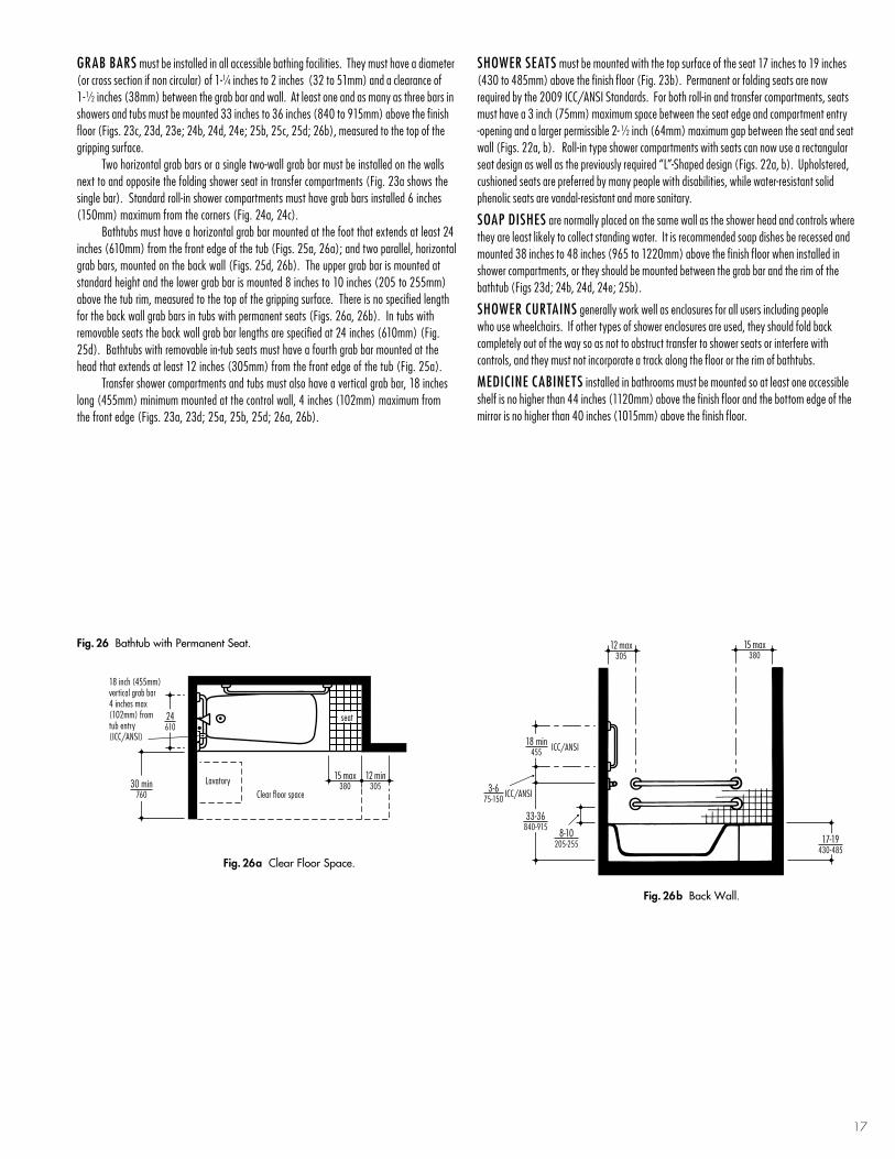
17
grab barS must be installed in all accessible bathing facilities. They must have a diameter (or cross section if non circular) of 1-1⁄4 inches to 2 inches (32 to 51mm) and a clearance of 1-1⁄2 inches (38mm) between the grab bar and wall. At least one and as many as three bars in showers and tubs must be mounted 33 inches to 36 inches (840 to 915mm) above the finish floor (Figs. 23c, 23d, 23e; 24b, 24d, 24e; 25b, 25c, 25d; 26b), measured to the top of the gripping surface. Two horizontal grab bars or a single two-wall grab bar must be installed on the walls next to and opposite the folding shower seat in transfer compartments (Fig. 23a shows the single bar). Standard roll-in shower compartments must have grab bars installed 6 inches (150mm) maximum from the corners (Fig. 24a, 24c). Bathtubs must have a horizontal grab bar mounted at the foot that extends at least 24 inches (610mm) from the front edge of the tub (Figs. 25a, 26a); and two parallel, horizontal grab bars, mounted on the back wall (Figs. 25d, 26b). The upper grab bar is mounted at standard height and the lower grab bar is mounted 8 inches to 10 inches (205 to 255mm) above the tub rim, measured to the top of the gripping surface. There is no specified length for the back wall grab bars in tubs with permanent seats (Figs. 26a, 26b). In tubs with removable seats the back wall grab bar lengths are specified at 24 inches (610mm) (Fig. 25d). Bathtubs with removable in-tub seats must have a fourth grab bar mounted at the head that extends at least 12 inches (305mm) from the front edge of the tub (Fig. 25a). Transfer shower compartments and tubs must also have a vertical grab bar, 18 inches long (455mm) minimum mounted at the control wall, 4 inches (102mm) maximum from the front edge (Figs. 23a, 23d; 25a, 25b, 25d; 26a, 26b).
ShoWer SeaTS must be mounted with the top surface of the seat 17 inches to 19 inches (430 to 485mm) above the finish floor (Fig. 23b). Permanent or folding seats are now required by the 2009 ICC/ANSI Standards. For both roll-in and transfer compartments, seats must have a 3 inch (75mm) maximum space between the seat edge and compartment entry -opening and a larger permissible 2- 1⁄2 inch (64mm) maximum gap between the seat and seat wall (Figs. 22a, b). Roll-in type shower compartments with seats can now use a rectangular seat design as well as the previously required “L”-Shaped design (Figs. 22a, b). Upholstered, cushioned seats are preferred by many people with disabilities, while water-resistant solid phenolic seats are vandal-resistant and more sanitary.
Soap diSheS are normally placed on the same wall as the shower head and controls where they are least likely to collect standing water. It is recommended soap dishes be recessed and mounted 38 inches to 48 inches (965 to 1220mm) above the finish floor when installed in shower compartments, or they should be mounted between the grab bar and the rim of the bathtub (Figs 23d; 24b, 24d, 24e; 25b).
ShoWer CUrTainS generally work well as enclosures for all users including people who use wheelchairs. If other types of shower enclosures are used, they should fold back completely out of the way so as not to obstruct transfer to shower seats or interfere with controls, and they must not incorporate a track along the floor or the rim of bathtubs.
MediCine CabineTS installed in bathrooms must be mounted so at least one accessible shelf is no higher than 44 inches (1120mm) above the finish floor and the bottom edge of the mirror is no higher than 40 inches (1015mm) above the finish floor.
Fig. 26b Back Wall.
3-675-150
33-36840-915
8-10205-255
ICC/ANSI
12 max305
15 max380
18 min455 ICC/ANSI
17-19430-485
Fig. 26 Bathtub with Permanent Seat.
Fig. 26a clear Floor Space.
12 min305
15 max380
Lavatory
seat
Clear floor space30 min
760
24610
18 inch (455mm) vertical grab bar 4 inches max (102mm) from tub entry (ICC/ANSI)

18
Fig. 27 Bathroom with Transfer Shower compartment.
Z
T
B
FF
W
N
P
L
K
Q R CCCE
EE
F
18 inch (455mm) vertical grab bar 4 inches max (102mm) from shower entry (ICC/ANSI)
36 x 36915 x 915
Transfer shower with folding seat
8 feet - 4 inches254cm
36915
36915
401016
Shower curb
1/2 max13
6 feet - 8 inches203cm
60 min1525
Wheelchairturning space
56 x 60 min1420 x 1525
Clear floor spaceat toilet
30 x 48760 x 1220
Clear floor spaceat lavatory
36 x 48 min915 x 1220
Clear floor space at shower compartment
legend a B-5806 x 18 Horizontal Grab Bar used as towel barb B-5806 x 18 Vertical Grab Bar C B-5806.99 x 18 Vertical Grab Bar with Peened Gripd B-5806.99 x 24 Horizontal Grab Bar with Peened Gripe B-5806 x 36 Horizontal Grab BarF B-5806 x 42 Horizontal Grab Barg B-5806.99 x 48 Horizontal Grab Bar with Peened Griph B-5837 Horizontal Two-Wall Grab Bar, 36" x 54" (915 x 1370mm)
J B-58616.99 Shower Grab Bar with Peened Grip, 24" x 36" (610 x 915mm)K B-6861.99 Shower Grab Bar with Peened Grip, 15- 7⁄8" x 30- 7⁄8" (405 x 785mm)l B-517 Folding Shower Seat, Padded Seat, Right-Hand SeatM B-5181 Reversible Folding Shower Seat, Solid Phenolic, Left-Hand Seatn B-4380 Recessed Soap Dishp B-6107 Shower Curtain RodQ 204-1 Shower Curtain Hooks
r 204-2 Vinyl Shower Curtain, 42" W x 72" H (1065 x 1830mm)S 204-3 Vinyl Shower Curtain, 70" W x 72" H (1780 x 1830mm)T 819843 Recessed Toilet Seat Cover Dispenser, Sanitary Napkin Disposal, Toilet Tissue Dispenser on left when facing unit with Theft-Resistant SpindleU B-6977 Recessed Toilet Tissue Dispenser for Two Rollsv B-359 Recessed Paper Towel DispenserW B-369 Recessed Paper Towel Dispenser and Waste Receptacle
X B-3644 Recessed Waste ReceptacleY B-8397 Surface-Mounted Facial Tissue DispenserZ B-165 Series Wall-to-Wall Mirror aa B-165 Series Mirror, 18" W x 36" H (455 x 915mm)bb B-165 Series Mirror, 33" W x 36" H (840 x 915mm)CC B-2116 Single Robe/Clothes Hook with Concealed Mountingdd B-76717 Single Robe/Clothes Hookee B-76727 Double Robe/Clothes HookFF B-3706 Recessed Sanitary Napkin/Tampon Vendor
DeSign SolUtionS foR bAtHRooMS WitH SHoWeR coMPARtMentS
Fig. 28 Bathroom with Wet-area Shower compartment.
TBCC
D
G
N
D
S
Q
W
EE
R
P
AA
H
Wall-hung lavatorywith insulated or
enclosed piping below
Hand-heldshower head
Roll-in shower compartment runs full width of enclosure
No curb at shower threshold
9 feet274cm
641626
30760
781981
7 feet - 4 inches224cm
30 min760
Clearance width at shower compartment
60 min1525
Wheelchairturning space 56 x 60 min
1420 x 1525Clear floor space
at toilet
30 x 48760 x 1220
Clear floor spaceat lavatory
Vertical grab bar 18 inches (455mm) long (ICC/ANSI)
Vertical grab bar 18 inches (455mm) long (ICC/ANSI)

19
Fig. 29 Bathroom with enlarged Roll-in Shower compartment.
T
X
B
H BB
P
V
G
N
G
G
Q
S
CC
EE
601525
30 min760
Clearance width at shower compartment
12 feet - 8 inches386cm
7 feet - 8 inches234cm
7 feet213cm
60 min1525
No curb at shower thresholdEnlarged roll-in shower stall
24610
30 x 48760 x 1220
Clear floor spaceat lavatory
56 x 60 min1420 x 1525
Clear floor spaceat toilet
Vertical grab bar 18 inches (455mm) long (ICC/ANSI)
Fig. 30 Bathroom with Roll-in Shower compartment.
DDJ E
Q
S
PU
F
B
EE
AY
M
N
Z
32815
8 feet244cm
No curb at shower threshold
Countertop lavatory with knee space and a protective panel below
Provide minimum 18 inches (460mm) clear to pullside of door, 24 inches (610mm) recommended
Hand-heldshower head
8 feet - 6 inches259cm
601525
38965
60 min1525
Wheelchair turning space
30 x 60760 x 1525
Clear floor space atshower compartment
56 x 60 min1420 x 1525
Clear floor spaceat toilet
30 x 48760 x 1220
Clear floor spaceat lavatory
Vertical grab bar 18 inches (455mm) long (ICC/ANSI)

20
legend a B-5806 x 18 Vertical Grab Barb B-5806 x 18 Horizontal Grab Bar used as towel barC B-5806.99 x 18 Horizontal Grab Bar with Peened Grip d B-5806.99 x 18 Vertical Grab Bar with Peened Gripe B-5806.99 x 24 Horizontal Grab Bar with Peened GripF B-5806 x 36 Horizontal Grab Barg B-5806 x 42 Horizontal Grab Barh B-5806.99 x 48 Horizontal Grab Bar with Peened Grip
J B-5837 Horizontal Two-Wall Grab Bar, 36" x 54" (915 x 1370mm)K B-4380 Recessed Soap Dishl B-6107 Shower Curtain RodM 204-1 Shower Curtain Hooks n 204-2 Vinyl Shower Curtain, 42" W x 72" H (1065 x 1830mm)p 204-3 Vinyl Shower Curtain, 70" W x 72" H (1780 x 1830mm)
Q 819843 Recessed Toilet Seat Cover Dispenser, Sanitary Napkin Disposal, Toilet Tissue Dispenser on left when facing unit with Theft-Resistant Spindle r B-6977 Recessed Toilet Tissue Dispenser for Two RollsS B-369 Recessed Paper Towel Dispenser and Waste ReceptacleT B-8397 Surface-Mounted Facial Tissue DispenserU B-165 Series Wall-to-Wall Mirror v B-165 Series Mirror, 18" W x 36" H (455 x 915mm)
W B-2116 Single Robe/Clothes Hook with Concealed MountingX B-76717 Single Robe/Clothes HookY B-76727 Double Robe/Clothes HookZ 1082 Series Solid Phenolic Shower Dividers with Shower Curtain Track in underside of headrailaa 1082 Series Solid Phenolic Dressing Compartments with Curtain Track in underside of headrail
DeSign SolUtionS foR bAtHRooMS WitH tUb/SHoWeR UnitS
Fig. 31 Bathroom with enlarged alternate Roll-in Shower compartment.
D
K
F
X L MN
T
U
B
Y
H
R A G
721830
56 x 601420 x 1525
Clear floor spaceat toilet
30 x 48760 x 1220Clear spaceat lavatory
10 feet - 4 inches315cm
No curb at shower threshold
36915
601525
8 feet - 4 inches254cm
60 min1525
Wheelchairturning space
Rectangular shower seat available from others
Vertical grab bar 18 inches (455mm) long (ICC/ANSI)
Fig. 32 Bathroom with combination Tub/Shower unit and Portable Seat.
K E
C
B
YV
EKDT
S
L X
PM
A JQ
601525
17430
30 x 60760 x 1525
Clear floor spaceat bathtub
6 feet - 6 inches198cm
Portable tub seat
30760
872210
9 feet - 9 inches297cm
60 min1525
Wheelchairturning space
56 x 60 min1420 x 1525
Clear floor spaceat toilet
Portable tub seat available from others
18 inch (455mm) vertical grab bar 4 inches max (102mm) from tub/shower entry (ICC/ANSI)
Vertical grab bar 18 inches (455mm) long (ICC/ANSI)

21
Fig. 34 Multiple Shower installation with enlarged Roll-in Shower compartment and Dressing compartment.
H
KH
P
K K K
Z Z Z
AA AA AA
N
AA
H
W
W
W W W
P M L
N N
N N N
601525
36 typ915
No curb at shower threshold
Dressing bench 24 inches max depth x 48 inches (610 x 1220mm) with toe clearance. Bench surface should not accumulate water and should be slip resistant.Bench available from others
621575
601525
36 typ915
30 x 48 min760 x 1220
Clear floor spacefor bench
17-19430-485
Seat height above floor
11 feet - 4 inches345cm
30 x 60760 x 1525
Clear floor space atshower compartment
DeSign SolUtionS foR MUltiPle SHoWeR coMPARtMentS AnD DReSSing coMPARtMentS
Fig. 33 Bathroom with combination Tub/Shower unit with Permanent Seat.
H
E
K
D
G
A
R
F T V
YX
M P L
K
9 feet274cm
6 feet - 3 inches191cm
7 feet - 3 inches221cm
15 min380
Wall-hung lavatorywith insulated or
enclosed piping below
30 x 87760 x 2210
Clear floor spaceat bath tub and seat
(overall length of tub and seat plus 12 inches min
(305mm))
Integral tub seat
12 min305
56 x 60 min1420 x 1525
Clear floor spaceat toilet
60 min1525
Wheelchair turning space
18 inch (455mm) vertical grab bar 4 inches max (102mm) from tub/shower entry (ICC/ANSI)
Vertical grab bar 18 inches (455mm) long (ICC/ANSI)

22
legend a B-5806.99 x 18 Vertical Grab Bar with Peened Gripb B-5806.99 x 30 Horizontal Grab Bar with Peened GripC B-6861.99 Shower Grab Bar with Peened Grip, 15- 7⁄8" x 30- 7⁄8" (405 x 785mm)d B-4380 Recessed Soap Dish
e B-5181 Reversible Folding Shower Seat, Solid Phenolic, Right-Hand SeatF B-6107 Shower Curtain Rodg 204-1 Shower Curtain Hooks h 204-2 Vinyl Shower Curtain, 42" W x 72" H (1065 x 1830mm)
J 204-3 Vinyl Shower Curtain, 70" W x 72" H (1780 x 1830mm)K B-2116 Single Robe/Clothes Hook with Concealed Mountingl 1082 Series Solid Phenolic Shower Dividers with Shower Curtain Track in underside of headrail
M 1082 Series Solid Phenolic Dressing Compartments with Curtain Track in underside of headrail
DeSign SolUtionS foR MUltiPle SHoWeR coMPARtMentS AnD DReSSing coMPARtMentS
Fig. 35 Multiple Shower installation with Transfer Shower compartment and Dressing compartment.
D
H
K K K
L
M
L
M
L
M
M
H H
H H HK
C
D D
BF
K G H A D
E
K
J
36 typ915
7 feet - 8 inches234cm
36 1/2925
36 1/2925
Shower curb
1/2 max13
17-19430-485
Seat height above floor
36 x 48915 x 1220
Clear floor spaceat shower compartment
30 x 48 min760 x 1220
Clear floor spacenext to bench
9 feet - 10 inches300cm
60 min1525
Wheelchair turning spaceDressing bench 24 inches max depth x 42 inches min length (610 x 1065mm) with toe clearance. Bench surface should not accumulate water and should be slip resistant. Bench available from others
18 inch (455mm) vertical grab bar 4 inches max (102mm) from shower entry (ICC/ANSI)

Accessible And Usable Buildings And Facilities, ICC/ANSI A117.1–2009. International Code Council500 New Jersey Avenue, NW, 6th FloorWashington, DC 20001American National Standard Institute25 West 43rd StreetNew York, NY 10036(Approved October 20, 2010)
For questions and technical information: 888-422-7233, Ext. 4306
Significant Changes to the A117.1 Accessibility Standard, 2009 Edition. Woodward, Jay. ICC International Code Council. 500 New Jersey Avenue, NW, 6th Floor. Washington, DC 20001. (2011)
2010 ADA Standards for Accessible Design.U.S. Department of Justice (September, 2010)Website: www.ADA.govADA Information Line 800-514-0301(Voice) or 800-514-0383 (TTY)
ADA National Network (formerly, Disability and Business Technical Assistance Centers [DBTAC])Website: www.adata.org
Regional Information Line800-949-4232 [voice/tty]
Guidance on the 2010 ADA Standards for Accessible Design. U.S. Department of Justice (September 15, 2010)Website: www.ADA.govAdditional copies may be obtained by calling the ADA Information Line: 800-514-0301 (voice) 800-514-0383 (TTY)
Inclusive Child Care: Design Solutions for Creating More Usable Child Care Facilities, Young, Leslie C., Hawley, Marsha. National Easter Seals Society, Chicago, Illinois. (2003). http://www.easterseals.com
Universal Design Principles. NC State University(1997)Website: www.udinstitute.org
b ibl iogRAPHY AnD ReSoURceS
cReDitS
Bobrick wishes to thank Ronald L. Mace, FAIA and Rex J. Pace for their invaluable contributions to the initial creation and previous editions of this planning guide. Bobrick also wishes to thank Richard Duncan, MRP, Executive Director, RL Mace Universal Design Institute, Chapel Hill, NC for assistance with the development of the 2012 publication.
Bobrick has Architectural Representatives located throughout North America available to provide technical assistance with compliance of washroom layouts and equipment selection. They are backed by Bobrick’s Architectural Services Department, which maintains extensive up-to-date files on building codes and engages in ongoing dialogue with code originators and enforcement agencies on a regular basis.
ARcHitectURAl RePReSentAt iVeS
Three plan views of a person in a wheelchair are illustrated in scales of 1/8" = 1'-0" (1:100 metric), 1/4" = 1'-0" (1:50 metric), and 1/2" = 1'-0" (1:25 metric). The template is printed on clear rigid plastic so it can be placed over drawings to confirm proper wheelchair clearance and maneuverability. It is especially helpful in designing entrances, lavatory areas, and toilet compartments.
WHEELCHAIR MANEUVERABILITY DRAWING TEMPLATE
BOBRICK.COM
© 2Rectangle is 30" x 48"(760 x 1220mm) Clear Floor Space 00 6 Bobrick Washroom Equipment, Inc.
60" min.(1525mm)
1/2" = 1'-0"1:25
(Metric)
Scale1/4"1:5
= 0
(1'-0"Metric)
Scale 1/8" = 1:100
1'-0"(Metric)
201 2 -
bobriCK’S WheelChair ManeUverabiliTY draWing TeMplaTe
23

loS angeleS: bobriCK WaShrooM eQUipMenT, inC.11611 Hart Street, North Hollywood, CA 91605-5882Corporate Offices: (818) 764-1000, FAX: (818) 765-2700Customer Service: (818) 982-9600, FAX: (818) 503-9287 e-mail: [email protected]
JaCKSon, Tn: 100 Bobrick DriveJackson, TN 38301-5625(731) 424-7000, FAX: (731) 424-7800
neW YorK: bobriCK WaShrooM eQUipMenT, inC.200 Commerce Drive, Clifton Park, NY 12065-1350Customer Service: (518) 877-7444, FAX: (518) 877-5029 e-mail: [email protected]
gaMCo CoMMerCial reSTrooM aCCeSSorieSA Division of BobrickOne Gamco Place, Durant, OK 74701-1910(800) 451-5766, FAX: (580) 920-2050e-mail: [email protected]
Koala Kare prodUCTSA Division of Bobrick6982 S. Quentin St.Centennial, CO 80112-3945(888) 733-3456, FAX: (303) 539-8399e-mail: [email protected]
Canada: bobriCK WaShrooM eQUipMenT CoMpanY45 Rolark Drive, Scarborough, Ontario M1R 3B1Ontario East: (877) 423-6555, FAX: (877) 423-8555e-mail: [email protected] Manitoba West: (877) 423-6444, FAX: (877) 423-8444e-mail: [email protected]
inTernaTional SaleS: 11611 Hart StreetNorth Hollywood, CA 91605-5882 USA+1 (818) 764-1000, FAX: +1 (818) 503-9941e-mail: [email protected]
aUSTralia : bobriCK WaShrooM eQUipMenT pTY.lTd.1800 353158, FAX: 1800 221926e-mail: [email protected]
gerManY: bobriCK WaShrooM eQUipMenT0800 79 00 456, FAX 0800 79 00 789e-mail: [email protected]
UniTed KingdoM: bobriCK WaShrooM eQUipMenT lTd.+44 (0)20 8366 1771, FAX: +44 (0)20 8363 5794e-mail: [email protected]
NOTE: The information contained herein is of an advisory nature only and represents Bobrick’s interpretation of the 2010 ADA and 2009 ICC/ANSI Standards referred to herein as of the date of publication. Bobrick assumes no responsibility for final code compliance. Users of this Planning Guide are advised to confirm all specifications with appropriate authorities. Due to the complexity of the Standards, and the potential for multiple, and even conflicting, interpretations of the Americans with Disabilities Act and 2010 ADA Standards for Accessible Design and ICC/ANSI A117.1 2009, it is recommended the layout of a restroom involve the services of a design professional proficient in accessible design.
bobR icK WASHRooM eQUiPMent, inc.
Form No. PGAR-12 15M May, 2012 © 2012 Bobrick Washroom Equipment, Inc. Printed in U.S.A.