tool steels - clarkandosborne.com · tool steels are vastly different from steel ... note the size...
TRANSCRIPT
Tool Steelsfor Punch & Matrix Components

©2001 Dayton Progress CorporationAll Rights Reserved.
1
1
2Selecting the proper Tool Steels, Heat Treatment, & Surface Treatments for
a stamping application can be a complex and confusing process. To simplify this process, a few basic facts should be understood.
This program will present and examine facts using terms familiar to the non-metallurgist.
The objectives of this program are shown.
3Tool steels are vastly different from steel used in consumer goods. They
are made on a much smaller scale. Strict quality procedures assure that a given grade of tool steel will perform a specific task such as machining or perforating.
Many different qualities in tool steels are desired based on a particular appli-cation. These qualities are provided by adding a particular alloy along with the appropriate amount of carbon. The alloy combines with carbon to enhance the wear, strength, or toughness characteristics. The combination also contrib-utes to the ability to resist thermal and mechanical stress.
The typical analysis shown contains some of the commonly used tool steels and their alloy content. Each of the alloy elements listed contributes to a spe-cific characteristic in the finished steel. They can also create undesirable side effects, particularity when used in excess. Alloy elements can have reactions with each other, which can either enhance or degrade the steel.
4If toughness were the only factor in choosing a tool steel, S7 would be the
obvious choice. Unfortunately toughness is achieved at the expense of other characteristics which are also necessary in most stamping applications.
The graph shows a toughness comparison for tool steels commonly used in stamping applications. They are listed in order of increasing alloy content from left to right. There is a tendency for tool steels to decrease in tough-ness as alloy content increases. The increase in alloy content also demands a higher price.
Toughness is also affected by the manufacturing process of the steel. The PM (Particle Metallurgy) process can greatly enhance the toughness of a given grade of tool steel over its conventional counterpart. Note the difference in toughness between M4 and CPM® M4 in the chart.
Hardness also affects toughness. CPM® 10V is shown twice in the chart. Any given grade of tool steel will have greater toughness at a lower hardness. The lower hardness could have a negative effect on other char-acteristics necessary to achieve sufficient tool life.
Jektole® is a registered trademark of Dayton Progress Corp. MoST™ is a trademark of MultiArc Inc. CPM® is a registered trademark of Crucible Materials Corporation. Rockwell® is a registered trademark of Instron Corporation.

2
5Increased alloy content typically results in increased wear resistance as
illustrated. Increased hardness also contributes to wear resistance. Note the increase
when the hardness of CPM® 10V is raised from RC 60 to RC 63. This hap-pens with all grades of tool steel.
6Compressive strength is a little known and often overlooked characteristic
of tool steels. It is a measurement of the maximum load an item can with-stand before deforming or before a catastrophic failure occurs.
Two factors affect compressive strength. They are alloy content and punch material hardness.
Alloy elements such as Molybdenum and Tungsten contribute to compres-sive strength. Higher hardness does as well.
7A common location for failure from excessive compressive loading is in the
radius blend. Not all radius blend failures are due to compressive load. Grinding burn
and lateral deflection of the punch point may also result in similar failures.The two punches pictured are identical in design with one exception. The
left punch is made from M2 tool steel and has lasted through years of use. The right punch is made from A2 and failed after a few hits. Even though both punches are of equal hardness, the M2 punch has a higher compressive strength allowing it to withstand high load applications.
8Punch deformation is another form of compressive failure. Deformation
can occur at the point or, as in the punch shown, behind the guide in the stripper.
Properly tempered tool steels can bend or deform before they break.

3
9This illustration compares toughness, wear resistance and compressive
strength. While some steels possess exceptional values with one characteris-tic, they tend to have low values in one or both of the other characteristics.
High load applications such as punching stainless steel, spring steel and high strength low alloy require tool steels with a combination of shock resis-tance, wear resistance and high compressive strength. M2 or PM-M4 work best in these applications.
10The Conventional Metallurgy Process for making tool steels involves melt-
ing scrap iron and adding alloy elements as needed. This mix is then poured into ingots where it is allowed to slowly cool.
Because different elements solidify at different temperatures, they begin to segregate as the ingot cools. The alloy elements tend to be found in higher concentration toward the center of the ingot.
Higher levels of alloy content result in an increased chance of segregation. Too much alloy segregation can lead to cracking, resulting in poor quality. For this reason, extremely high alloy tool steels can not be manufactured by conventional means.
11The Particle Metallurgy Process of steel making begins much like the
conventional process with the melting of iron and the adding of appropriate alloy elements.
The alloy is then poured through an atomizing vessel where the stream of molten metal is exposed to high velocity jets of an inert gas. This gas breaks up the stream of metal into small droplets that rapidly cool to form a fine powder.
The sudden cooling prevents alloy segregation. Each grain of the powder contains the entire alloy content.
The powder is screened and filled into a mild steel can, called a compact, where it is mechanically compacted and sealed.
The compact is loaded into a hot isostatic press where it is exposed to high heat and pressure. This process compresses the compact to nearly 100% density to form a solid billet of steel.
12The billet is then forged and rolled into plates and bars. This serves two
purposes.One is to bring the steel down to manageable sizes. The other reason is to
benefit the steel itself. Forging and rolling into smaller sizes improves the quality of the steel.
The rolling process, also called reduction, breaks up and redistributes the segregated alloys associated with conventional metallurgy. A more homoge-neous structure results from rolling. The greater the reduction, the better the structure for conventional metallurgy tool steels.
Particle metallurgy steels have a uniform distribution of carbides and there-fore are in less need of forging and rolling. This is why higher alloy tool steels in larger sizes perform better when made with the particle metallurgy process.

4
13This photomicrograph shows a comparison of Particle and Conventional
Metallurgy. Both samples contain the same alloy content. The black area is the matrix. The matrix bonds the steel together and
produces most of the steel’s measurable hardness.The white particles suspended in the matrix are the carbides. Carbides are
hard particles that give tool steels wear resistance. The amount of carbides is related to the amount of certain alloys such as Vanadium, Molybdenum, Chromium and Tungsten in conjunction with appropriate levels of carbon.
Small, evenly distributed spherical carbides, as seen in the Particle Metal-lurgy steel, offer benefits such as:
• Improved machining and grinding characteristics.• More consistent hardness response and size change in heat treatment.• Greater toughness (Shock resistance)
Note the size and directional distribution of carbides in the conventional steel. This is a result of the forging and rolling process. Carbides are broken down into smaller pieces and more uniformly distributed as a bar of conven-tional steel is rolled into smaller sizes improving its quality.
14Tool steels are only as good as the heat treatment they receive. The keys to
achieving optimum results in heat treatment are listed.Each grade of tool steel has specific heat treatment guidelines in order
to acquire optimum results for a given application. Unlike cutting tools, the nature of stamping operations places a high demand on toughness. This means that a grade of tool steel should be heat-treated differently for a cutting tool than if it were used in a stamping application.
Segregation in heat treatment by size of product is extremely important. Items of different sizes require adjustments in preheat, soak and quench rates. Fixturing assures even support and uniform exposure to heating and cooling in the heat treatment process.
15Tool steels are exposed to high temperature in the hardening process. This
heat is required to austenitize (soak) the steel. High heat can result in oxida-tion and changes in the level of carburization causing distortion and surface damage to the part. Vacuum furnaces offer the greatest amount of protection from these problems.
Cryogenics aids in the conversion of austenite to martensite, insuring greater hardness response and reduced stress. Tempering is accomplished at a much lower temperature and does not require a vacuum furnace. Radiant heat in a vacuum below approximately 760°C (1,400°F) is not reliable because of inefficient heat transfer. Additionally, thermocouples in a vacuum environ-ment at lower temperatures are not accurate, making temperature control unreliable. Convection tempering (recirculating air) eliminates these problems and provides uniform heating.
16This is what a typical vacuum furnace looks like from the outside. This
furnace has a two Bar, high velocity quench capability. This is one of four vacuum furnaces used at Dayton Progress’ main plant.

�
17This is an example of improper segregation by size. The small parts in the
foreground heat up much more rapidly than the larger parts behind them, leading to inconsistent and improper preheat, soak and quench rates. Ideally, parts should be segregated by size and mass to insure optimum tooling performance.
18Heat treatment support equipment is necessary in order for vacuum
heat treating equipment to operate up to its potential. The support equip-ment handles water for cooling and nitrogen or other medium necessary for quenching.
The large tank to the right is a nitrogen storage unit. The smaller tanks to either side are nitrogen surge units.
The tower to the left is for water cooling. This tower is part of a dual loop cooling system.
19A closer look at the nitrogen storage tank reveals a series of tubes with heat
exchanger fins mounted to its side. This heat exchanger assists in raising the nitrogen from a liquid state at -196°C (-320°F) to a gas at ambient tempera-ture.
The surge tanks hold enough nitrogen gas to quickly back-fill the furnace and quench the parts.
20The nitrogen gas is circulated across the parts where it absorbs heat. It is
then cooled in a water-to-air heat exchanger before being recirculated over the parts.
The water-cooling tower shown at the left of the picture performs the final transfer of heat. Heat from the water is dissipated into the outside air.

6
21The shape and size of the hot zone plays a critical part in the hardening
process. A small round hot zone assures a uniform temperature throughout.Heating elements and cooling nozzles in this furnace are positioned on all
sides to provide even heating and cooling.
22This diagram identifies the major components of a high velocity vacuum
furnace used in the process of vacuum hardening tool steels.1) The process starts by removing the atmosphere (vacuum) and electrically
heating the parts in the hot zone.2) After the parts are properly heated (austenitized) the system is backfilled
with nitrogen. Nitrogen is used as a means of conducting heat away from the parts. A large turbine blower forces room temperature nitrogen across the parts, cooling (quenching) them through the martensite transfer range.
3) Hot nitrogen exits the hot zone through gates at the front and rear of the chamber.
4) The nitrogen circulates through a heat exchanger where it is cooled.�) The cooled nitrogen is recirculated over the parts until they reach room
temperature.
23The first step for achieving optimum heat treatment begins with preheat-
ing. For cold work steels such as A2 and D2, this is accomplished by heating the parts to just below the critical austenitizing temperature of approximately 788°C (14�0°F), long enough to allow the part to be evenly heated. This is necessary because when the part enters the austenitizing temperature range, the steel is restructured on an atomic level creating a volume expansion. If this volume expansion does not occur uniformly, the part will distort and possibly crack.
Soaking (austenitizing) is heating the part into the carbide phase region for a specified period of time. The intention is to force some of the alloy elements into the matrix. Soaking cold work steels such as A2 or D2 at or above the high end of their austenitizing range (overheating) will result in excessive levels of retained austenite and generate a coarse grain structure. This will result in inferior toughness in the finished product.
Quenching is the sudden cooling of parts from the austenitizing tempera-ture through the martensite transfer range. The steel is transformed from austenite to martensite, resulting in hardened parts. Unfortunately cold work steels have a transformation range that goes well below room temperature. This is one reason why cold work steels benefit from freezing (cryogenics).
Tempering is necessary to remove stress associated with the hardening process. Cold work tool steels are generally tempered at or below 204°C (400°F). Due to the low tempering temperature involved, one temper is generally adequate for cold work tool steels.
24Due to the limitations of thermal couples at low temperatures in vacuum,
most tempers are performed in atmosphere. This picture shows two atmo-spheric furnaces at Dayton Progress.
7
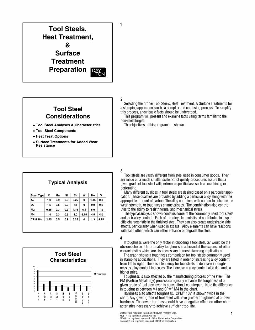
25High speed and high alloy steels such as M2, CPM-M4 and CPM-10V
require a somewhat different approach to heat treatment.Although the process initially appears similar to cold work tool steels, the
temperatures and number of tempers differ.Preheat temperatures begin at approximately 830°C (1�2�°F) and soak
temperatures can be above 1,093°C (2,000°F).Because the soak temperature is approaching the melting point, control
of both time and temperature are critical. Over soaking the part can result in incipient melting. This is when the alloys with lower melting points begin to melt within the item, damaging the steel structure.
Higher temper resistance found in high speed and high alloy tool steels allow tempering temperatures to be much higher than with cold work steels. The higher tempering temperatures are high enough to transform retained austenite left over from the quench as well as temper the untempered mar-tensite, eliminating the need for freezing (cryogenics). It typically takes three tempers above �38°C (1000°F) to reduce the levels of retained austenite and untempered martensite to acceptable levels.
26This graph illustrates the effects of multiple tempering on high-speed tool
steels.Tool steels as quenched contain a majority of untempered martensite and
approximately 30% retained austenite. Retained austenite and untempered martensite contain a great deal of stress which must be relieved or the tool will fail.
High speed and high alloy tool steels have good temper resistance, which allows them to be tempered at higher temperatures. Tempering at or above �38°C (1,000°F) will temper the untempered martensite and as the part cools, convert about half of the retained austenite into untempered martensite without reducing the part hardness below HRC 60. The effects of the higher tempering temperatures are enough to convert retained austenite to martens-ite reducing the need for cryogenic treatments on high speed and high alloy tool steels.
Standard heat treatment practice for high speed tool steels calls for at least two tempers. However, three tempers are necessary to bring the levels of retained austenite and untempered martensite to acceptable levels for stamp-ing operations.
27Head breakage is a one of the more common problems encountered in
stamping applications. Precise induction heating and slow cooling as shown in the illustration
above draws the heads down to a lower hardness (HRC 4� - ��) adding toughness to that area of the punch.
28Rockwell Hardness Testing is the most common test for the results of heat
treatment. Checking hardness on a cylindrical surface will provide less lateral support, resulting in a lower hardness reading.
The Wilson Instrument Division of the American Chain & Cable Company published the Wilson Cylindrical Correction Chart #�3 in 19�3. This chart provides approximate correction values based on observed readings from various hardnesses and diameters.
It is important to note that “the accuracy of the test will be seriously affected by alignment of the elevating screw, “V” anvil, penetrators, surface finish and straightness of the cylinder”
Rockwell scales can be used on diameters down to 1/4 inch. Superficial scales can be used down to 1/8 inch diameter. Diameters smaller than 1/8 inch should be checked using a Knoop indentor at very low pressures.

8
29Hardness testing accuracy will be improved by grinding parallel flats on
the part. Care should be taken when grinding these flats to not generate heat which can affect the hardness. The test must be conducted with a minimum distance of two and one half diameters of the test result from the edge of the flat.
Cylindrical corrections can be used when flats can not be ground on the part. These corrections can be found on the Wilson Cylindrical Correction Chart #�3.
30Misalignment of the elevating screw and “V” anvil to the indentor will result
in low readings and could possibly damage the diamond indentor.
31Values from the Wilson Cylindrical Correction Chart #�3 are to be added
to the observed readings taken from tests performed on 1/4 inch to 1 inch diameters when using the “A”, “C” & “D” Rockwell scales.
Tests performed on smaller diameters are invalid when using these scales.
32Surface treatments are often used as a means of improving tool life. These
treatments increase surface hardness and wear resistance while reducing the coefficient of friction.
Important considerations when selecting a surface treatment are substrate material, coating process temperature, coating thickness and coating hard-ness.

9
33There are many surface treatments and treatment processes to chose from.
Nitride is a treatment that case hardens the surface of the substrate mate-rial. This treatment can be applied by numerous processes. Fluidized Bed, Salt Bath and Gas are the most common and economical processes to apply nitride. Ion nitride is a good process but tends to be more expensive. Nitride surface treatments work in a broad range of applications. Salt Bath nitride is the best from an application point of view but has lost favor due to environ-mental concerns.
Titanium Nitride, Titanium Carbonitride and Chromium Nitride applied using Physical Vapor Deposition (PVD) work well on precision tooling when used in specific applications. Titanium Nitride offers better wear resistance than Nitride and MoST coating but experiences some difficulty when working with copper and stainless steel applications. Titanium Carbonitride and MoST provide even greater wear resistance and will work in stainless and copper applications.
Titanium Nitride and Titanium Carbide applied using the Chemical Vapor Deposition (CVD) process and Thermal Diffusion do well in forming applica-tions. These coatings work best in forming applications that do not require a high level of precision. Due to the high processing temperatures involved, precision is limited by distortion and changes in size.
34Coatings and surface treatments enhance wear resistance and reduce sur-
face friction above and beyond the capabilities of the substrate material. They do not, however, eliminate the cause for wear and galling. Applications with tight punch to matrix clearance or punch over entry may not see a significant improvement in tool life when adding surface treatments.
35Surface treatments can be applied to a wide variety of substrate materials
(tool steels) with varying results.Note the relatively low tempering temperature for cold work tool steels
such as A2 and D2. These temperatures are below the PVD and Nitride processing temperatures. Exposure to these temperatures will draw the hardness of cold work tool steels down to a hardness below HRC �8. Hardness below HRC �8 will leave the substrate steel vulnerable to defor-mation beneath the coating, creating adhesion problems for the coatings.
Part growth and distortion will also become factors which affect assem-bly of the tooling and precision of the finished product.
CVD process coatings are applied at the high end of the austenitizing range of cold work tool steels. Course grain structure and size change are to be expected in these circumstances. Precision and toughness will be questionable.
Thermal diffusion is a unique process that utilizes the carbon content within the substrate material to form the coating and quenches the tool as part of its coating cycle. It can be applied to D2 steel but the substrate hardness typically falls below HRC �8, potentially reducing the strength of the part.
36PVD process coatings and nitride work well with high speed and high alloy
tool steels such as M2, M4 and CPM-10V. The PVD process temperatures fall more than 30°C (�0°F) below the tempering temperature of high speed and high alloy tool steels, nearly eliminating distortion and growth in the part.
Due to the high processing temperature of CVD coatings and thermal dif-fusion (TD), post-heat treatment is commonly required to achieve acceptable hardness of the substrate material. Distortion and growth are to be expected.
Because of its utilization of carbon within the substrate material, TD will work well on steels with high carbon content such as M4 and CPM-10V in low to moderate precision applications. Thermal diffusion is not recommended on M2 due to its relatively low carbon content.

10
37Coating thickness becomes an issue in high precision applications.Nitride is a process of case hardening the existing surface of the part.
Although nitride does not build up on the surface, the heat involved may cause slight growth in the part as a result of the matrix accommodating the diffusion of nitrogen.
PVD coatings are relatively thin and only cover areas within the line of sight of the coating source. Precision of the coated area is generally maintained and fit at tool assembly is typically not affected by this process.
CVD and TD coating processes are thicker and cover the entire part affect-ing precision of the working end and fit in a retainer. Stripping and reworking portions of punches may be necessary to assemble the tooling.
38Like tool steels, hardness is an indication of wear resistance and lubric-
ity for a given coating. PVD process coatings and nitride enhance the life of precision high speed and high alloy tool steels but will not cure wear problems caused by tight die clearance or punch bending problems due to high load.
Higher hardness coatings such as titanium carbide and thermal diffusion tend to be thicker and require a great deal of heat to apply, eliminating them from use in many precision applications.
The hardness values in the above graph are of the coatings themselves. Because these coating are extremely thin, their values can not be measured using a Rockwell hardness tester. The coating hardness is virtually undetect-able on the Rockwell “C” scale.
39The following pages cover considerations and recommendations regarding
the sharpening and welding of tool steel components.
40Care should be taken when sharpening punches and matrixes. Heavy
passes with a grinding wheel, use of the wrong grinding wheel, an undressed grinding wheel or lack of coolant are just some of the causes of grinding damage.
11
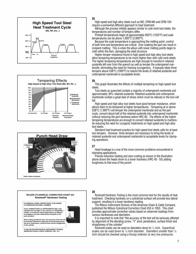
41A closer look at the points of these punches reveals several types of grind-
ing damage.The discoloration, surface cracks and flaking are the visual results of grind-
ing damage. Internal stress and changes in hardness also affect the tool life.The face has begun the flake off of these punches due to rapid surface
heating. The surface has expanded at a much faster rate than the rest of the punch, causing it to separate.
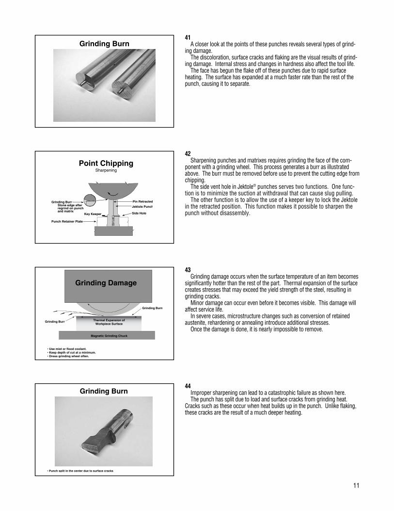
42Sharpening punches and matrixes requires grinding the face of the com-
ponent with a grinding wheel. This process generates a burr as illustrated above. The burr must be removed before use to prevent the cutting edge from chipping.
The side vent hole in Jektole® punches serves two functions. One func-tion is to minimize the suction at withdrawal that can cause slug pulling.
The other function is to allow the use of a keeper key to lock the Jektole in the retracted position. This function makes it possible to sharpen the punch without disassembly.
43Grinding damage occurs when the surface temperature of an item becomes
significantly hotter than the rest of the part. Thermal expansion of the surface creates stresses that may exceed the yield strength of the steel, resulting in grinding cracks.
Minor damage can occur even before it becomes visible. This damage will affect service life.
In severe cases, microstructure changes such as conversion of retained austenite, rehardening or annealing introduce additional stresses.
Once the damage is done, it is nearly impossible to remove.
44Improper sharpening can lead to a catastrophic failure as shown here.The punch has split due to load and surface cracks from grinding heat.
Cracks such as these occur when heat builds up in the punch. Unlike flaking, these cracks are the result of a much deeper heating.
12
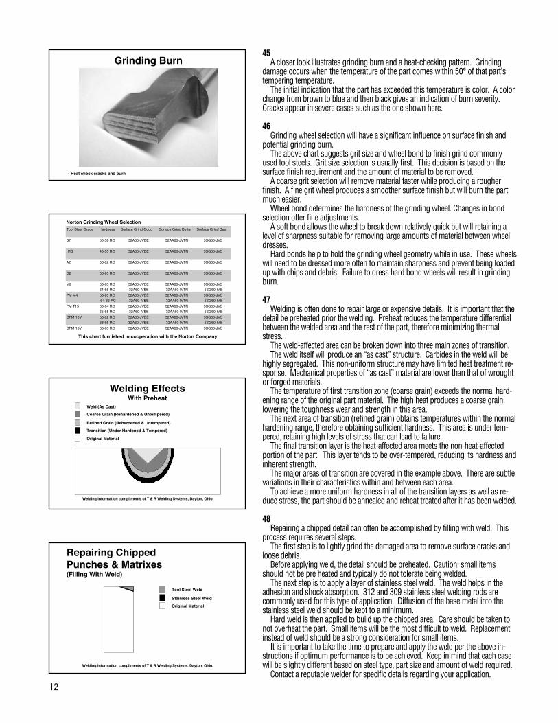
45A closer look illustrates grinding burn and a heat-checking pattern. Grinding
damage occurs when the temperature of the part comes within �0° of that part’s tempering temperature.
The initial indication that the part has exceeded this temperature is color. A color change from brown to blue and then black gives an indication of burn severity. Cracks appear in severe cases such as the one shown here.
46Grinding wheel selection will have a significant influence on surface finish and
potential grinding burn.The above chart suggests grit size and wheel bond to finish grind commonly
used tool steels. Grit size selection is usually first. This decision is based on the surface finish requirement and the amount of material to be removed.
A coarse grit selection will remove material faster while producing a rougher finish. A fine grit wheel produces a smoother surface finish but will burn the part much easier.
Wheel bond determines the hardness of the grinding wheel. Changes in bond selection offer fine adjustments.
A soft bond allows the wheel to break down relatively quick but will retaining a level of sharpness suitable for removing large amounts of material between wheel dresses.
Hard bonds help to hold the grinding wheel geometry while in use. These wheels will need to be dressed more often to maintain sharpness and prevent being loaded up with chips and debris. Failure to dress hard bond wheels will result in grinding burn.
47Welding is often done to repair large or expensive details. It is important that the
detail be preheated prior the welding. Preheat reduces the temperature differential between the welded area and the rest of the part, therefore minimizing thermal stress.
The weld-affected area can be broken down into three main zones of transition.The weld itself will produce an “as cast” structure. Carbides in the weld will be
highly segregated. This non-uniform structure may have limited heat treatment re-sponse. Mechanical properties of “as cast” material are lower than that of wrought or forged materials.
The temperature of first transition zone (coarse grain) exceeds the normal hard-ening range of the original part material. The high heat produces a coarse grain, lowering the toughness wear and strength in this area.
The next area of transition (refined grain) obtains temperatures within the normal hardening range, therefore obtaining sufficient hardness. This area is under tem-pered, retaining high levels of stress that can lead to failure.
The final transition layer is the heat-affected area meets the non-heat-affected portion of the part. This layer tends to be over-tempered, reducing its hardness and inherent strength.
The major areas of transition are covered in the example above. There are subtle variations in their characteristics within and between each area.
To achieve a more uniform hardness in all of the transition layers as well as re-duce stress, the part should be annealed and reheat treated after it has been welded.
48Repairing a chipped detail can often be accomplished by filling with weld. This
process requires several steps.The first step is to lightly grind the damaged area to remove surface cracks and
loose debris.Before applying weld, the detail should be preheated. Caution: small items
should not be pre heated and typically do not tolerate being welded.The next step is to apply a layer of stainless steel weld. The weld helps in the
adhesion and shock absorption. 312 and 309 stainless steel welding rods are commonly used for this type of application. Diffusion of the base metal into the stainless steel weld should be kept to a minimum.
Hard weld is then applied to build up the chipped area. Care should be taken to not overheat the part. Small items will be the most difficult to weld. Replacement instead of weld should be a strong consideration for small items.
It is important to take the time to prepare and apply the weld per the above in-structions if optimum performance is to be achieved. Keep in mind that each case will be slightly different based on steel type, part size and amount of weld required.
Contact a reputable welder for specific details regarding your application.


Global leader in quality metal fabrication and stamping tools
DAYTON PROGRESS CORPORATION 500 Progress Road P.O. Box 39 Dayton, Ohio 45449-0039 USA Telephone: (937) 859-5111 Fax: (937) 859-5353
Dayton Progress Canada, Ltd. 861 Rowntree Dairy Road Woodbridge, Ontario L4L 5W3 Telephone: (905) 264-2445 Fax: (905) 264-1071
Dayton Progress Ltd. G1 Holly Farm Business Park Honiley, Kenilworth Warwickshire CV8 1NP UK Telephone: 44 1 926 484192 Fax: 44 1 926 484172
Dayton Progress Corporation of Japan 2-7-35 Hashimotodai Sagamihara-Shi, Kanagawa-Ken 229-1132 Japan Telephone: 81 427 74 0821 Fax: 81 427 73 4955
Dayton Progress GmbH Im Heidegraben 8 Postfach 1165 61401 Oberursel/Ts., Germany Telephone: 49 61 71 924201 Fax: 49 61 71 924220
Dayton Progress SAS 105 Avenue de l’Epinette BP 128 Zone Industrielle 77107 Meaux Cedex France Telephone: 33 1 60 247301 Fax: 33 1 60 247300
Form 8033 2/01