top-technic - cdmecdme.com.cy/schrack/relays.pdf · top-technic w pluggable interface relay xt w...
TRANSCRIPT

RELAYS
Page
424
TOP-TECHNIC
W MINIATURE RELAY PTW PLUGGABLE INTERFACE RELAY XT
W MULTIMODE RELAY MT W POWER RELAY RM
W PCB RELAY RY II W RELAY WITH FORCE GUIDED CONTACTS SR4D/M
W MEASURING AND MONITORING RELAY SERIES 5
W MEASURING AND MONITORING RELAY SERIES 6

Page
425
RELAYS
RELAYS
w CONTENTS
GENERAL INFORMATION ........................................................................ Page 426
PANEL RELAYS AND ACCESSORIES .................................................. Page 428
PCB RELAYS...................................................................................................... Page 462
FORCE GUIDED RELAYS .......................................................................... Page 467
MODULAR RELAYS ...................................................................................... Page 472
TIME RELAYS ................................................................................................ Page 474
LOAD SHEEDING RELAY .......................................................................... Page 501
MONITORING RELAYS................................................................................ Page 502
“To assign each deed the proper amount of effort is the secret of vitality.”
Prentice Mulford, American journalist

RELAYS - GENERAL INFORMATION
Page
426
W STRUCTURE OF A RELAY
W THE CONTACT MATERIALS
One of the most important criteria of a relay; it is crucial for the application.Silver-Nickel AgNi90/10• High resistance against electrical wear, low welding tendency, higher contact resistance than AgNi0.15• Circuits with medium to high loads, DC and AC circuits, recommended range of application > 12 V, 10 mAFine-Grain Silver AgNi0.15• Relatively low contact resistance, low resistance against aggressive atmosphere• Universally applicable in medium and low load range, especially in DC circuits, recommended range of
application > 12 V, 10 mASilver-Tin-Oxide AgSnO2• Low welding tendency, high wear resistance with heavy loads, low material transfer• Circuits with high requirements to make- and break-currents, DC and AC loads, recommended range of
application > 12 V, 100 mA Tungsten W• Highest melting point, for high switching rates and low ON-time• As prerun contact in circuits with highest make loads Silver-Cadmium-Oxide AgCdO • Low welding tendency, high wear resistance • For switching of inductive loads, AC circuits, > 12 V, 100 mAPlating materials: Hard gold plated (htv)• Very good corrosion resistance, low and stable contact resistance at lowest loads, low tendency to cold
welding• Dry-circuit switching (without current/voltage), recommended range of application > 1 V, 1 mA, 50 mW
W THE COIL
Although sensitive power consumption is important,the attraction force is an essential criterion.
W THE SPRING AND THE YOKE
The leaf spring offers the assurance of a strong springforce and a long service life of the relay.
W PIN – THE PLUG-IN DESIGN
The pins must be found always according to the requi-rements on the printed circuit board, or in accordancewith the base.

RELAYS - GENERAL INFORMATION
Page
427
W WORKING PRINCIPLE OF A RELAY
W WORKING PRINCIPLE OF A COIL DEPENDING ON THE VOLTAGE
Coil types, AC coil 50 HzCoil- LED Rated Operation Release Coil Rated Opt. LED
code voltage voltage voltage resistance power power
50 Hz 50 Hz 50 Hz 50 Hz
V∼ V∼ V∼ Ohm VA VA
524 R24 24 18.0 3.6 350±10% 0.76 0.012
615 S15 115 86.3 17.3 8100±15% 0.76 0.054
730 T30 230 172.5 34.5 32500±15% 0.74 0.073
Data apply to coil without pre-excitation, ambient temperature + 23 °C.
Other coil types on request.
Maximum voltage
Holding voltage
Release voltage
Ratedvoltage
Operationvoltage
NoneOperation

PANEL RELAYS AND ACCESSORIES
Page
428
W SCHRACK-INFO• Relay package consisting of relays and DIN rail mount• 1 CO contact with 6 A nominal current• Reinforced insulation (protection class II, VDE 0160)• Module width only 6.2 mm• Reduced system width for increase packing density on the DIN rail• Complies with the RoHS Directive 2002/95/EC• Encoded protction diode and LED
W RELAY PACKAGE SNR
SNR
w DIMENSIONS (mm)
Typenschlüssel S T P
TypeVersion
3P Relais Package, SNR 1-polig, Wechsler, 6 A, Schraubanschlüsse4P Relais Package, SNR 1-polig, Wechsler, 6 A, Federklemmen
Kontaktwerkstoff2 AgSnO2, hartvergoldet 3 AgSnO2
SpuleLB2 12 VDC LC4 24 VDCSM5 115 VDC/VAC TP0 230 VDC/VAC
w LOAD BREAKING CAPACITY
w TYPE KEY
Relay package, SNR 1-pole, CO, 6 A, screw terminals
Max. DC load breaking capacity
DC
vol
tage
[V
DC
]
DC current [A]
Resistive load
Contact material
Coil
AgSnO2, gold-plated, htv
Relay package, SNR 1-pole, CO, 6 A, cage-clamp terminals

PANEL RELAYS AND ACCESSORIES
Order no. blue: on stock, usually ready for delivery on the day of order!
Page
429
CONTACTS COIL CONTACT MATERIAL TYPE EAN CODE AVAILABLE ORDER NO.
RELAY PACKAGE, 6 A WITH SOCKET
1 CO, screw
terminal 12 V DC AgSnO2 SNR PACKAGE 12VDC SK 9004840408614 ST3P3LB2
1 CO, screw
terminal 24 V DC AgSnO2 SNR PACKAGE 24VDC SK 9004840408553 ST3P3LC4
1 CO, screw AgSnO2,
terminal 24 V DC hard gold-plated SNR PACKAGE 24VDC SK REL.HTV. 9004840408546 ST3P2LC4
1 CO, screw
terminal 115 V AC/DC AgSnO2 SNR PACKAGE 115VDC/AC SK 9004840408560 ST3P3SM5
1 CO, screw
terminal 230 V AC/DC AgSnO2 SNR PACKAGE 230VDC/AC SK 9004840408577 ST3P3TP0
1 CO, screwless
terminal 24 V DC AgSnO2 SNR PACKAGE 24VDC FK 9004840407860 ST4P3LC4
1 CO, screwless
terminal 230 V AC/DC AgSnO2 SNR PACKAGE 230VDC/AC FK 9004840407884 ST4P3TP0
ACCESSORIES
SNR screw base 9004840448931 ST3FLC4
SNR jumper bar, red 500 mm ST3x, ST4x 9004840407914 ST37001
SNR jumper bar, blue 500 mm ST3x, ST4x 9004840407921 ST37002
SNR jumper bar, grey 500 mm ST3x, ST4x 9004840407938 ST37003
Label per pc. ST3x, ST4x 9004840407891 ST37040
CONTACT DATA 6 A
Contact configuration 1 CO
Contact set Single contact
Type of interuption Micro-switch
Rated current 6 A
Rated voltage / max. switching voltage AC 240 / 240 VAC
Max. breaking capacity AC 1500 VA
Limiting making capacity, max 4 s, duty factor 10% 10 A
Contact material AgSnO2,AgSnO2 gold-plated
LED and PD for DC voltage
INPUT DATA
Rated input voltage DC 12, 24 VDC, 115, 230 VAC/VDC (type 115, 230 VAC/VDC with 60 VDC relay)
Rated coil power, DC coil 12 VDC 184 mW, 24 VDC 220 mW, 115 VAC 402 mVA, 230 VAC 736 mVA
Operation range to IEC 61810 2
GENERAL DATA
Ambient temperature range - 40... + 55 °C
Degree of protection DIN 40050 IP20
Terminals Screw terminals / cage-clamp terminals
Terminal screw torque according to IEC 61984 0.5 Nm
max. 0.6 Nm
Wire cross section Solid wire 0.14...2.5 mm2
Stranded wire 0.14...2.5 mm2
with ferrule (DIN 46228/1) 0.14...2.5 mm2
Visit www.schrack.com for further technical data
w TECHNICAL DATA

PANEL RELAYS AND ACCESSORIES
Page
430
W SCHRACK-INFO• 1-pole 12 / 16 A, DC or AC coil• 1 CO contact or 1 NO contact• Sensitive coil 400 mW / 0.75 VA• 5 kV / 10 mm coil contact, class II (VDE 0700)• Safe separation according to VDE 0160 in conjunction with base YRT78626• Ambient temperature 85 °C (DC coil)• Low overall height 15.7 mm• Hard gold-plated contacts available• PCB and screw bases are available• Typical applications: panel boards, mechanical engineering
W POWER RELAY RT1
RT1
S0272-AB
V
Z
w APPROVALSw DIMENSIONS (mm) w LOAD BREAKING CAPACITY
12 A, Pinning 3,5 mm
1 Wechsler
1 Schließer
12 A, Pinning 5 mm
1 Wechsler
1 Schließer
16 A, Pinning 5 mm
1 Wechsler
1 Schließer
S0418-BB S0418-BN S0
S0S0163-BCS0163-BG
S0163-BH S0163-BD S0
Ansicht auf die AnschlüsseAbmessungen in mm
*) Bestückung bei angegebenemLochdurchmesser auch im Rastermass 2,5 mmoder 2,54 mm möglich.
w PCB DIAGRAMS/WIRING DIAGRAMS
w COIL OPERATING VOLTAGE RANGE
Max. DC load breaking capacityD
C v
olta
ge [
VD
C]
DC current [A]
Resistive load
View of the terminals, dimensions in mm
12 A, pinning 3.5 mm
1 CO1 CO
1 NO 1 NO 1 NO
1 CO
12 A, pinning 5 mm 16 A, pinning 5 mm
*) Equipping with indicated hole diameter also possible in 2.5 mm or 2.54 mm contact spacing.

PANEL RELAYS AND ACCESSORIES
Page
431
C
CONTACTS PINNING COIL CONTACT MAT. TYPE EAN CODE AVAILABLE ORDER NO.
12 A
1 CO 3.5 mm 12 V DC AgNi 90/10 PREL-SL-1-UKE-M1-012G-12-3.5 9004840160604 RT114012
1 CO 3.5 mm 24 V DC AgNi 90/10 PREL-SL-1-UKE-M1-024G-12-3.5 9004840160611 RT114024
1 CO 3.5 mm 24 V AC AgNi 90/10 PREL-SL-1-UKE-M1-024W-12-3.5 9004840193466 RT114524
1 CO 5 mm 12 V DC AgNi 90/10 PREL-SL-1-UKE-M1-012G-12-5.0 9004840155846 RT214012
1 CO 5 mm 24 V DC AgNi 90/10 PREL-SL-1-UKE-M1-024G-12-5.0 9004840155143 RT214024
1 CO 5 mm 230 V AC AgNi 90/10 PREL-SL-1-UKE-M1-230W-12-5.0 9004840158182 RT214730
16 A
1 CO 5 mm 5 V DC AgNi 90/10 PREL-SL-1-UKE-M1-005G-16-5.0 9004840167856 RT314005
1 CO 5 mm 12 V DC AgNi 90/10 PREL-SL-1-UKE-M1-012G-16-5.0 9004840185553 RT314012
1 CO 5 mm 24 V DC AgNi 90/10 PREL-SL-1-UKE-M1-024G-16-5.0 9004839015489 RT314024
1 NO 5 mm 24 V DC AgNi 90/10 PREL-SL-1-AKE-M1-024G-16-5.0 9004840158151 RT334024
1 CO 5 mm 110 V DC AgNi 90/10 PREL-SL-1-UKE-M1-110G-16-5.0 9004840196238 RT314110
1 CO 5 mm 24 V AC AgNi 90/10 PREL-SL-1-UKE-M1-024W-16-5.0 9004840157994 RT314524
1 CO 5 mm 230 V AC AgNi 90/10 PREL-SL-1-UKE-M1-230W-16-5.0 9004839034596 RT314730
1 CO 5 mm 230 V AC AgNi 90/10 PREL-SL-1-UKE-M1-230W-16-5.0 9004840193503 RT315730
1 CO 5 mm 24 V DC AgNi 90/10 PREL-SW-1-UKE-M1-024G-16-5.0 9004840193619 RTD14024
CONTACT DATA 12 A 16 A
Number of contacts and type 1 CO or 1 NO contact
Contact style Single contact
Rated current 12 A 16 A
Rated voltage / max. switching voltage AC 250 V∼ / 440 V∼
Max. breaking capacity AC 3000 VA 4000 VA
Inrush current (max. 4 s at 10% DF) 25 A 30 A
Contact material AgNi 90/10. AgNi 90/10 htv
COIL DATA
Nominal voltage DC coil 5...110 V∼
AC coil 24...230 V∼
Nominal power DC coil 400 mW – 420 mW
AC coil 0.74 VA – 0.76 VA
Operation release voltage/coil resistance 24 VDC coil 16.8 V / 2.4 V / 1440 Ÿ ± 10%
at ambient temperature 23 °C 230 VAC coil 172.5 V / 34.5 V / 32500 Ÿ ± 10%
Visit www.schrack.com for further technical data
w TECHNICAL DATA
w TYPE KEY
1 12 A, pinning 3.5 mm, flux-proof2 12 A, pinning 5 mm, flux-proof3 16 A, pinning 5 mm, flux-proof
Type
Version
Contacts
Contact material
1 CO 1 NO
16 A, pinning 5 mm, wash-proof,
AgNi 90/10 gold-plated (for type RT31.)
For coil code, see coil table
Preferred types in bold print
Coil
Order no. blue: on stock, usually ready for delivery on the day of order!

PANEL RELAYS AND ACCESSORIES
Page
432
S0272-AB
W POWER RELAY RT1 INRUSH
W SCHRACK-INFO• 1-pole, 16 A, for inrush peak currents • 1 NO or 1 CO contact• Sensitive coil 400 mW • 5 kV / 10 mm coil contact• Protection class II (VDE 0700)• Ambient temperature 85 °C • Low overall height 15.7 mm (only relay)• PCB and screw bases• For domestic appliances, heating controls, lighting controls, building automation
V
Zb
w APPROVALSw DIMENSIONS (mm)
w LOAD BREAKING CAPACITY
Ansicht auf die AnschlüsseAbmessungen in mm
*) Bestückung bei angegebenemLochdurchmesser auch im Rastermass 2,5 mmoder 2,54 mm möglich.
16 A, Pinning 5 mm 1 Schließer
w PCB DIAGRAMS/WIRING DIAGRAMS
RT1 INRUSH
w COIL OPERATING VOLTAGE RANGE
Max. DC load breaking capacity
DC
vol
tage
[V
DC
]
DC current [A]
Resistive load
View of the terminals, dimensions in mm
16 A, pinning 5 mm 1 NO
*) Equipping with indicated hole diameter also possible in 2.5 mm or 2.54 mm contact spacing.

PANEL RELAYS AND ACCESSORIES
Page
433
D 16 A, Pinning 5 mm, waschdicht
CONTACT DATA
Number of contacts and type 1 NO contact
Contact style Single contact
Rated current 16 A
Rated voltage / max. switching voltage AC 250 V∼ / 440 V∼
Max. breaking capacity AC 4000 VA
Inrush current (max. 4 s at 10% DF) 30 A
Contact material AgNi 90/10, AgSnO2
COIL DATA
Rated voltage 5...110 V∼
Rated power 400 mW
Operation release voltage/coil resistance 24 VDC coil 16.8 V / 2.4 V / 1440 Ÿ ± 10%
at ambient temperature 23°C
Visit www.schrack.com for further technical data
w TECHNICAL DATA
w TYPE KEY
2
CONTACTS PINNING COIL CONTACT MAT. TYPE EAN CODE AVAILABLE ORDER NO.
16 A
1 NO 5 mm 24 V DC AgNi 90/10 PREL-SL-1-AKE-M1-024G-16-5.0 9004840158793 RT33K024
1 CO 5 mm 24 V DC AgSnO2 PREL-SL-1-UKE-M1-024G-16-5.0 9004840155280 RT31L024
1 1 CO contact 3 1 NO contact
Type
Version
Contacts
Contact material
CoilCoil code: please see coil table, preferred types in bold print
16 A, pinning 5 mm
Order no. blue: on stock, usually ready for delivery on the day of order!
I KNOW WHERE TO FIND IT!
THE SCHRACK TECHNIK WEB SHOP WITH NAVIGATORWWW.SCHRACK.COM
• Finding product information made easy
• Buying products around the clock
• Quick access customer service

PANEL RELAYS AND ACCESSORIES
Page
434
W POWER RELAYS RTI
W SCHRACK-INFO• 1-pole 16 A, 1 NO contact (W pre-make contact + AgSnO2)• 10 A / 250 V AC making and breaking capacity according to IEC 60669-1• 165 A / 20 ms inrush peak current • Mono- or bistable coil • 5 kV / 10 mm coil contact set• Reinforced insulation• Complies with the RoHS Directive 2002/95/EC• For lighting systems, movement sensors, incandescent and fil lamps, motors
RTI
V
Zb
w APPROVALS
w LOAD BREAKING CAPACITY
16 A, Pinning 5 mm
b) nur bei 2 Wicklungen
*) Bestückung bei angegebenemLochdurchmesser im Rastermaßvon 2,5 mm bis 2,54 mm möglich.
monostabile Ausführung
w PCB DIAGRAMS/WIRING DIAGRAMS
S0272-AB
w DIMENSIONS (mm)
w COIL OPERATING VOLTAGE RANGE
Max. DC load breaking capacity
DC
vol
tage
[V
DC
]
DC current [A]
Resistive load
16 A, pinning 5 mm
b) only for 2 windings
Monostable version
*) Equipping with indicated hole diameter also possible in 2.5 mm or 2.54 mm contact spacing.

PANEL RELAYS AND ACCESSORIES
Page
435
Typenschlüssel R T 3
TypeBauart
S ohne Prüfhebel T mit Prüfhebel (Handbetätigung)nur mit Kontaktwerkstoff ‘T’ und bistabiler Spule
Kontaktausführung3 1 Schließer
KontaktwerkstoffL AgSnO2 T Wolfram-Vorlaufkontakt + AgSnO2
SpuleSpulencode siehe Tabelle Spulenausführungen
TYPENSCHLÜSSEL
CONTACT DATA RT.3T RTS3L
Contact type 1 NO contact
Contact style Single contact
Type of disconnection Micro-switch
Rated current 16 A
Rated voltage / max. switching voltage AC 250 / 400 VAC
Limiting continuous current 16 A
Max. breaking capacity AC 4000 VA
Limiting making capacity max 20 ms (incandescent lamps) 165 A 120 A
max 200 μs (fluorescent lamps) 800 A -
Contact material W (lead contact)+AgSnO2 AgSnO2
COIL DATA
Rated voltage range 24 VDC
Rated power Typ. 400 mW
Operation range, IEC 61810 2
Coil insulation system according to UL1446 Class F
Operation release voltage/coil resistance 24 VDC coil 16.8 V / 2.4 V / 1440 Ÿ ± 10%
at ambient temperature 23 °C 230 VAC coil 172.5 V / 34.5 V / 32500 Ÿ ± 10%
Visit www.schrack.com for further technical data
w TECHNICAL DATA
w TYPE KEY
CONTACTS PINNING COIL CONTACT MAT. TYPE EAN CODE AVAILABLE ORDER NO.
16 A
1 NO 5 mm 24 V DC AgSnO2 PREL-SL-1-AKE-M1-024G-16-5 9004840515855 RTS3L024
1 NO 5 mm 24 V DC W + AgSnO2 PREL-SL-1-AKE-M1-024G-16-5 9004840543476 RTS3T024
I KNOW WHERE TO FIND IT!
WITH THE SCHRACK TECHNIK LiVE-PHONE APP
• Access technical product information at any time and from everywhere
• See availability and price immediately
• Order desired products easily
Version
Contact style1 NO
Contact material
CoilCoil code: please refer to coil version table
Tungsten pre-contact + AgSnO2
Order no. blue: on stock, usually ready for delivery on the day of order!
S

PANEL RELAYS AND ACCESSORIES
Page
436
W POWER RELAYS RT2
W SCHRACK-INFO• 2-pole 8 A, DC or AC coil• 2 CO contact • Sensitive coil 400 mW • DC or AC coil• 5 kV / 10 mm coil contact, class II (VDE 0700), reinforced insulation• Safe separation according to VDE 0160 in conjunction with base YRT78626• Low overall height 15.7 mm (only relay)• PCB and screw bases• For domestic appliances, heating controllers, emergency lighting, modems, panel boards,
mechanical engineering
RT2
S0272-AB
V
ZbB
w APPROVALSw DIMENSIONS (mm) w LOAD BREAKING CAPACITY
Ansicht auf die AnschlüsseAbmessungen in mm
S0418-BA
*) Bestückung bei angegebenemLochdurchmesser auch im Rastermass 2,5 mmoder 2,54 mm möglich.
2 Wechsler
2 Schließer
w PCB DIAGRAMS/WIRING DIAGRAMS
w COIL OPERATING VOLTAGE RANGE
Max. DC load breaking capacityD
C v
olta
ge [
VD
C]
DC current [A]
2-poleresistive load
2 contacts in series
1 contact
View of the terminals, dimensions in mm
2 CO
2 NO*) Equipping with indicated hole diameter also possible in 2.5 mm or 2.54 mm contact spacing.

PANEL RELAYS AND ACCESSORIES
Page
437CONTACTS PINNING COIL CONTACT MAT. TYPE EAN CODE AVAILABLE ORDER NO.
8 A
2 CO 5 mm 6 V DC AgNi 90/10 PREL-SL-2-UKE-M1-006G-08-5.0 9004840158939 RT424006
2 CO 5 mm 12 V DC AgNi 90/10 PREL-SL-2-UKE-M1-012G-08-5.0 9004839019241 RT424012
2 CO 5 mm 24 V DC AgNi 90/10 PREL-SL-2-UKE-M1-024G-08-5.0 9004839019142 RT424024
2 CO 5 mm 24 V DC AgNi 90/10, htv PREL-SL-2-UKE-M1-024G-08-5.0 9004840160628 RT425024
2 CO,
wash-tight 5 mm 24 V DC AgNi 90/10 PREL-SL-2-UKE-M1-024G-08-5.0 9004839029103 RTE24024
2 CO 5 mm 48 V DC AgNi 90/10 PREL-SL-2-UKE-M1-048G-08-5.0 9004839027185 RT424048
2 CO 5 mm 60 V DC AgNi 90/10 PREL-SL-2-UKE-M1-060G-08-5.0 9004840193558 RT424060
2 CO 5 mm 110 V DC AgNi 90/10 PREL-SL-2-UKE-M1-110G-08-5.0 9004840191561 RT424110
2 CO 5 mm 24 V AC AgNi 90/10 PREL-SL-2-UKE-M1-024W-08-5.0 9004839034602 RT424524
2 CO 5 mm 48 V AC AgNi 90/10 PREL-SL-2-UKE-M1-048W-08-5.0 9004840167641 RT424548
2 CO 5 mm 115 V AC AgNi 90/10 PREL-SL-2-UKE-M1-115W-08-5.0 9004840158021 RT424615
2 CO 5 mm 115 V AC AgNi 90/10. htv PREL-SL-2-UKE-M1-115W-08-5.0 9004840187748 RT425615
2 CO 5 mm 230 V AC AgNi 90/10 PREL-SL-2-UKE-M1-230W-08-5.0 9004839034282 RT424730
2 CO 5 mm 230 V AC AgNi 90/10. htv PREL-SL-2-UKE-M1-230W-08-5.0 9004840166040 RT425730
E 8 A, Pinning 5 mm, waschdicht
CONTACT DATA 8 A
Number of contacts and type 2 CO contact
Contact style Single contact
Rated current 8 A
Rated voltage / max. switching voltage AC 250 V∼ / 440 V∼
Max. breaking capacity AC 2000 VA
Inrush current (max. 4 s at 10% DF) 15 A
Contact material AgNi 90/10. AgNi 90/10 htv
COIL DATA
Rated voltage DC coil 5...110 V∼
AC coil 24...230 V∼
Rated power DC coil 400 mW (24 VCD)
AC coil 0.74 VA (230 VAC)
Operation release voltage/coil resistance 24 VDC coil 16.8 V / 2.4 V / 1440 Ÿ ± 10%
at ambient temperature 23 °C 230 VAC coil 172.5 V / 34.5 V / 32500 Ÿ ± 10%
Visit www.schrack.com for further technical data
w TECHNICAL DATA
w TYPE KEY
TypeVersion
Contacts
gold-plated, htvContact material
CoilFor coil code, see coil table
Preferred types in bold print
8 A, pinning 5 mm, wash-proof,8 A, pinning 5 mm, flux-proof
2 CO
Order no. blue: on stock, usually ready for delivery on the day of order!
PANEL RELAYS AND ACCESSORIES
Page
438
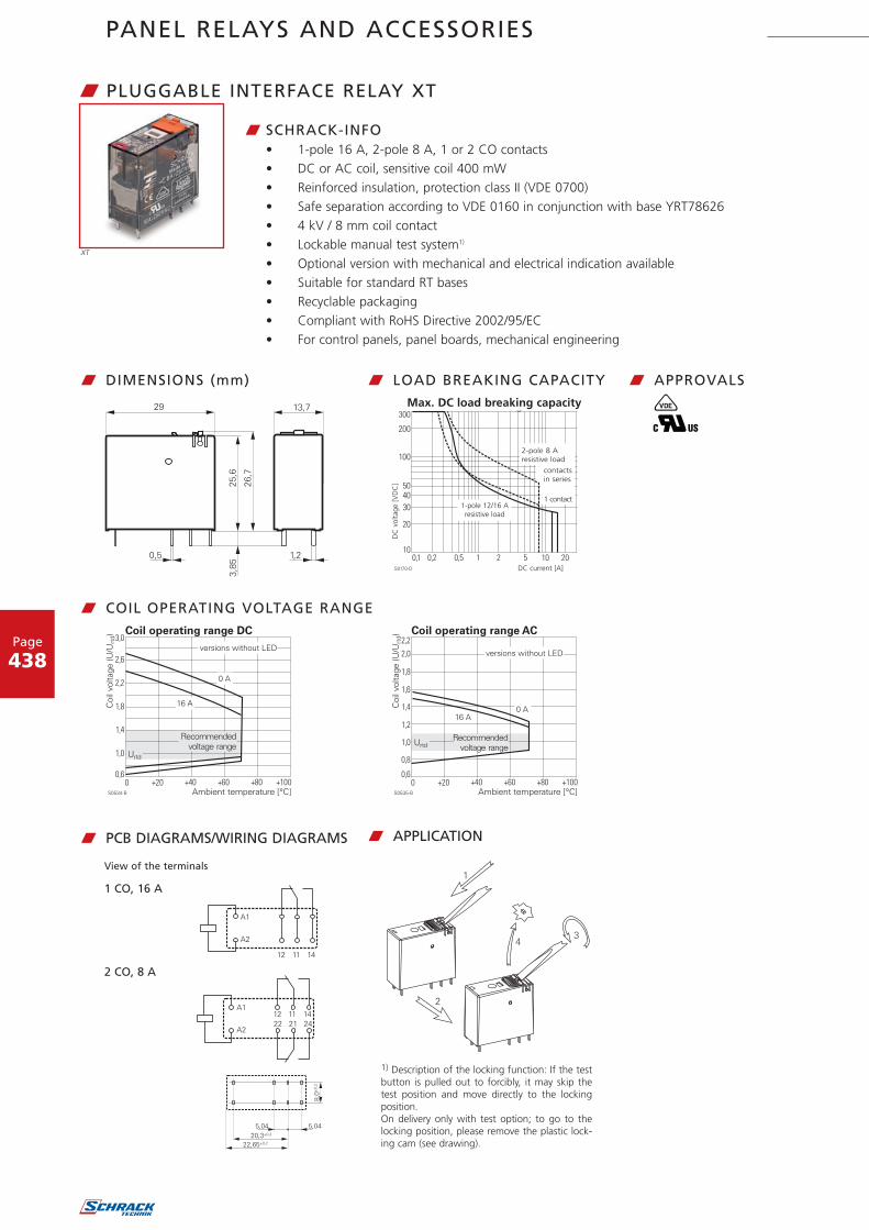
W PLUGGABLE INTERFACE RELAY XT
W SCHRACK-INFO• 1-pole 16 A, 2-pole 8 A, 1 or 2 CO contacts• DC or AC coil, sensitive coil 400 mW• Reinforced insulation, protection class II (VDE 0700)• Safe separation according to VDE 0160 in conjunction with base YRT78626• 4 kV / 8 mm coil contact• Lockable manual test system1)
• Optional version with mechanical and electrical indication available• Suitable for standard RT bases• Recyclable packaging• Compliant with RoHS Directive 2002/95/EC• For control panels, panel boards, mechanical engineering
XT
s0538_A
V
Z
w DIMENSIONS (mm)
w PCB DIAGRAMS/WIRING DIAGRAMS
w LOAD BREAKING CAPACITY
S0163-BE
S0163-BJ
s0538_BB
View of the terminals
1 CO, 16 A
2 CO, 8 A
1) Description of the locking function: If the testbutton is pulled out to forcibly, it may skip thetest position and move directly to the lockingposition.On delivery only with test option; to go to thelocking position, please remove the plastic lock-ing cam (see drawing).
W APPLICATION
w APPROVALS
w COIL OPERATING VOLTAGE RANGE
Max. DC load breaking capacityD
C v
olta
ge [
VD
C]
DC current [A]
1-pole 12/16 A resistive load
2-pole 8 Aresistive load
contactsin series
1 contact
PANEL RELAYS AND ACCESSORIES
Page
439
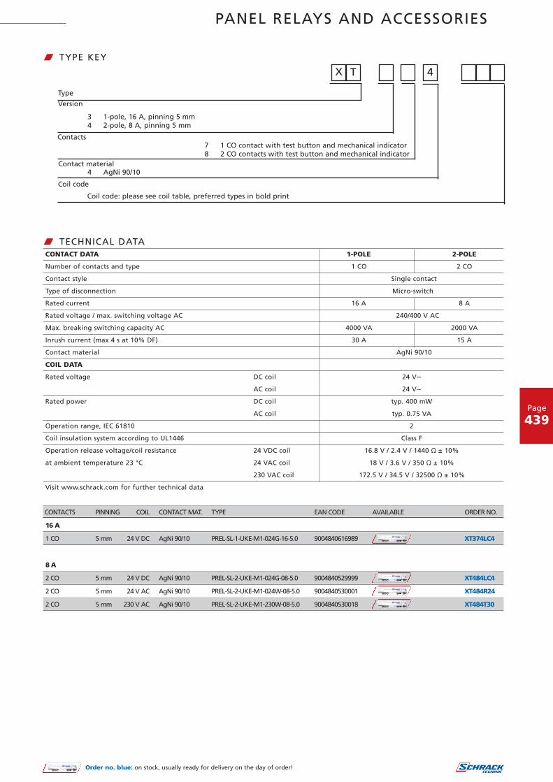
CONTACTS PINNING COIL CONTACT MAT. TYPE EAN CODE AVAILABLE ORDER NO.
16 A
1 CO 5 mm 24 V DC AgNi 90/10 PREL-SL-1-UKE-M1-024G-16-5.0 9004840616989 XT374LC4
8 A
2 CO 5 mm 24 V DC AgNi 90/10 PREL-SL-2-UKE-M1-024G-08-5.0 9004840529999 XT484LC4
2 CO 5 mm 24 V AC AgNi 90/10 PREL-SL-2-UKE-M1-024W-08-5.0 9004840530001 XT484R24
2 CO 5 mm 230 V AC AgNi 90/10 PREL-SL-2-UKE-M1-230W-08-5.0 9004840530018 XT484T30
CONTACT DATA 1-POLE 2-POLE
Number of contacts and type 1 CO 2 CO
Contact style Single contact
Type of disconnection Micro-switch
Rated current 16 A 8 A
Rated voltage / max. switching voltage AC 240/400 V AC
Max. breaking switching capacity AC 4000 VA 2000 VA
Inrush current (max 4 s at 10% DF) 30 A 15 A
Contact material AgNi 90/10
COIL DATA
Rated voltage DC coil 24 V∼
AC coil 24 V∼
Rated power DC coil typ. 400 mW
AC coil typ. 0.75 VA
Operation range, IEC 61810 2
Coil insulation system according to UL1446 Class F
Operation release voltage/coil resistance 24 VDC coil 16.8 V / 2.4 V / 1440 Ÿ ± 10%
at ambient temperature 23 °C 24 VAC coil 18 V / 3.6 V / 350 Ÿ ± 10%
230 VAC coil 172.5 V / 34.5 V / 32500 Ÿ ± 10%
Visit www.schrack.com for further technical data
w TECHNICAL DATA
W TYPE KEY
Type
Version
Contacts
3 1-pole, 16 A, pinning 5 mm4 2-pole, 8 A, pinning 5 mm
Contact material
Coil code
Coil code: please see coil table, preferred types in bold print
4 AgNi 90/10
7 1 CO contact with test button and mechanical indicator8 2 CO contacts with test button and mechanical indicator
X T 4
Order no. blue: on stock, usually ready for delivery on the day of order!

PANEL RELAYS AND ACCESSORIES
Page
440
W ACCESSORIES FOR POWER AND INTERFACE RELAYS RT AND XT – GENERAL INFORMATION
W SCHRACK-INFO• For industrial power relays RT and XT, pinning 3.5 mm or 5 mm• Plug-in base with separate terminal positions (input/output)• New holding clip with ejection function• Easy change of the relays even with dense packing• High-quality, contact-reliable terminal screws• Captive terminal screws• Indicator and function modules reverse polarity-protected and easy to plug in• Snap-on labels• Complies with the RoHS Directive 2002/95/EC
RT78725 RT17017
XT484LC4 XT17017 YRT78626
RT424730 YMLRW230
I KNOW WHERE TO FIND IT!
THE SCHRACK TECHNIK WEB SHOP WITH NAVIGATORWWW.SCHRACK.COM
• Finding product information made easy
• Buying products around the clock
• Quick access customer service

PANEL RELAYS AND ACCESSORIES
Page
441
S0545-BA
W SCREWLESS CLAMP SOCKET WITH SCREWLESS TERMINALS FOR DIN RAIL MOUNTING
W SCHRACK-INFO• Screwless terminals• Solid wire can be connected without tools• Double clamps per terminal• Jumper bars for connection• Open coil circuit for active modules• Inputs and outputs arranged separately
w DIMENSIONS (mm)
Öffnungszugang
Leiteröffnung
Ja Ja
Querbrückungskamm
W APPLICATION / CAUTIONS
Rated current 2 x 8 A, 16 A*)
Rated voltage / max. switching voltage 240/400 V AC
Terminal capacity Solid wire 1 x 0.75 / 1 / 1.5 mm2, 2 x 0.75 / 1 mm2
Stranded wire without ferrule 1 x 0.75 / 1 / 1.5 mm2, 2 x 0.75 / 1 mm2
without ferrule, with standard insulation 2 x 1.5 mm2
with ferrule 1 x 0.75 / 1 mm2, 2 x 0.75 mm2
with ferrule, without insulation or insulation at least 18 mm long 1 x 1.5 mm2
For stranded conductors with single wires of 0.05 mm or less, the used of ferrules is recommended. When using stranded conductors without ferrules, the terminal must be opened to insert the conductor.* Supply contacts of the 1-pole relays must be doubled on 1x + 2x!
w TECHNICAL DATA
Label
Relays
Bracket
Module
Opening access
Conductor opening
Jumper bar
YesYes
RT7872P
DESCRIPTION FOR RELAY TYPE EAN CODE AVAILABLE ORDER NO.
Screwless clamp socket, pinning 5 mm for DIN rail mounting RT2x, RT3x, RT4x, XT, RP4x 9004840535204 RT7872P
Retaining clip for RT relay (overall height 15.7 mm) RT2x, RT3x, RT4x 9004839096242 RT17017
Retaining clip for XT relay (overall height 25.5 mm) XT, RP4 9004839096143 XT17017
Jumper bar - 9004840539264 RT170P1
I KNOW WHERE TO FIND IT!
WITH THE SCHRACK TECHNIK LiVE-PHONE APP
• Access technical product information at any time and from everywhere
• See availability and price immediately
• Order desired products easily
Order no. blue: on stock, usually ready for delivery on the day of order!

PANEL RELAYS AND ACCESSORIES
Order no. blue: on stock, usually ready for delivery on the day of order!
Page
442
RT 78 724 RT 78 726
W SOCKET WITH SCREW TERMINALS FOR DIN RAIL
W SCHRACK-INFO• Easy change of the relay even with dense packing• High-quality, contact-reliable terminals• Captive terminal screws
w DIMENSIONS (mm)
YRT 78624 YRT 78626 RT 78725
Rated current 12 A 2 x 8 A, 16 A*) 2 x 8 A, 16 A*)
Rated voltage AC 240 V∼
Terminals Screw terminals
Terminal torque according to IEC 61984 0.5 Nm
max. 0.7 Nm
Terminal capacity copper wire 2 x 2.5 mm2
Stranded wire 2 x 2.5 mm2
with ferrule (DIN 46228/1) 2 x 1.5 mm2
* Supply contacts of the 1-pole relays (RT1) must be doubled on 1x + 2x!
w TECHNICAL DATA
w APPLICATION
S059-AR
w APPROVALS
YRT 78624 YRT 78626 RT 78725 Jumper bar
YRT78726/RT78725
DESCRIPTION FOR RELAY TYPE EAN CODE AVAILABLE ORDER NO.
Socket with screw terminals, logic version
pinning 3.5 mm for DIN rail mounting RT1x 9004840184921 YRT78624
Socket with screw terminals, logic version
pinning 5 mm for DIN rail mounting XT, RT2x, RT3x, RT4x 9004839900419 YRT78626
Socket with screw terminals, conventional version
pinning 5 mm for DIN rail mounting XT, RT2x, RT3x, RT4x 9004840546378 RT78725
Retaining clip f. RT relay w. eject function (overall height 15.7 mm) RT1x, RT2x, RT3x, RT4x 9004839096242 RT17017
Retaining clip f. XT relay w. eject function (overall height 25.5 mm) XT, RP4 9004839096143 XT17017
Jumper bar 8-fold - 9004840617030 RT170R8
Marking tag - 9004840184907 YRT16040
Label
Functionmodule
Relay
Bracket
Label
Functionmodule
Relay
Bracket

PANEL RELAYS AND ACCESSORIES
Page
443
W LED AND PROTECTION MODULES
W SCHRACK-INFO• Compatible with screwless and screw terminal sockets
YMLRW230
DESCRIPTION FOR SOCKET TYPE EAN CODE AVAILABLE ORDER NO.
LED red 6...24 V DC/V AC YPTx, PTx, YRTx, RTx EM07 9004839069253 YMLRA024
LED red 6...24 V DC with prot. diode (A1+, A2-) YPTx, PTx, YRTx, RTx EM18 9004839069192 YMLRD024-A
LED red 6...24 V DC with prot. diode (A1-, A2+) YPTx, PTx, YRTx, RTx EM08 9004840152203 YMLRD024
LED red 110...230 V AC YPTx, PTx, YRTx, RTx EM06 9004839069246 YMLRW230
LED green 6...24 V DC/V AC YPTx, PTx, YRTx, RTx EM11 9004839069222 YMLGA024
LED green 6...24 V DC with prot. diode (A1+, A2-) YPTx, PTx, YRTx, RTx EM12 9004839069239 YMLGD024
LED green 110...230 V AC YPTx, PTx, YRTx, RTx EM10 9004839034879 YMLGW230
Protection diode (A1+, A2-), 6/230 V DC YPTx, PTx, YRTx, RTx EM09 9004839069208 YMFDG230
RC network 6...60 V AC YPTx, PTx, YRTx, RTx EM02 9004840152272 YMRCW024
RC network 110...230 V AC YPTx, PTx, YRTx, RTx EM03 9004840152289 YMRCW230
Varistor 24 V AC YPTx, PTx, YRTx, RTx EM04 9004840194081 YMVAW024
Varistor 230 V AC YPTx, PTx, YRTx, RTx EM05 9004840194098 YMVAW230
Order no. blue: on stock, usually ready for delivery on the day of order!
I KNOW WHERE TO FIND IT!
THE SCHRACK TECHNIK WEB SHOP WITH NAVIGATORWWW.SCHRACK.COM
• Finding product information made easy
• Buying products around the clock
• Quick access customer service

PANEL RELAYS AND ACCESSORIES
Page
444
Löt- und Steckanschlüsse (Standardversion)
W MINIATURE RELAY PT
W SCHRACK-INFO• 2-pole 12 A, 3-pole 10 A
or 4-pole 6 A• AC or DC coil• Up to 3000 VA switching performance• Overall height 29 mm• Cadmium-free contact material
• Mechanical and optional electricalfunction indicator
• Touch-proof test button, selectable lock• White label• Universal use in control, automation
and mechanical engineering
V
ZL
w APPROVALSw DIMENSIONS (mm)
Typenschlüssel P T
TypeKontaktausführung
2 2 Wechsler3 3 Wechsler5 4 Wechsler
Kontaktwerkstoff7 AgNi 90/10, mit Prüftaste*) 8 AgNi 90/10 hartvergoldet, mit Prüftaste*)
Bauart0 Standard, 2,8 mm Flachstecker 1 Printanschlüsse
SpuleSpulencode siehe Tabelle Spulenausführungen, Vorzugstypen in Fettdruck
*) Version mit geschlossener Kappe ohne Prüftaste auf Anfrage.Andere Typen auf Anfrage
w LOAD BREAKING CAPACITY
(13)A1
(14)A2
(13)A1+
(14)A2-
LED Freilaufdiode+LED
w WIRING DIAGRAMS
w TYPE KEY
PT
w COIL OPERATING VOLTAGE RANGE
Max. DC load breaking capacity
DC
vol
tage
[V
DC
]
DC current [A]
Series circuit
Soldering and plug-in terminals (standard version)
4 contacts3 contacts2 contacts
1 contact Protection diode + LEDLED
2-3-pole4-pole
Resistive load
Type
Contact style
Contact material
Version
Coil
Standard, 2.8 mm flat connector
Coil code: please refer to coil version table, preferred types in bold print
*) Version with a closed cap without test button available on request. Other types available on request
Print terminals
AgNi 90/10, with test button AgNi 90/10 gold-plated, with test button
2 CO3 CO4 CO

PANEL RELAYS AND ACCESSORIES
Page
445
CONTACT DATA PT2 PT3 PT5
Contact version 2 CO 3 CO 4 CO
Contact style Single contact
Type of disconnection Micro-switch
Rated current 12 A 10 A 6 A
Rated voltage / max. switching voltage AC 240/400 VAC 240/400 VAC 240/240 VAC
Max. breaking capacity AC 3000 VA 2500 VA 1500 VA
Making capacity, max 20 ms 24 A 20 A 12 A
Contact material AgNi90/10. AgNi90/10 hard gold-plated
Minimum contact load 12V/10 mA, 20 mV/1 mA hard gold-plated
COIL DATA
Rated voltage range DC coil 6...220 VDC
AC coil 6...230 VAC
Rated output DC coil 0.75 mW
AC coil 1.0 VA
Operation release voltage/coil resistance 24 VDC coil 18 V / 2.4 V / 777 Ÿ ± 10%
at ambient temperature 23 °C 24 VAC coil 19.2 V / 7.2 V / 192 Ÿ ± 10%
230 VAC coil 184 V / 69 V / 19465 Ÿ ± 10%
Visit www.schrack.com for further technical data
w TECHNICAL DATA
CONTACTS COIL CONTACT MAT. TYPE EAN CODE AVAILABLE ORDER NO.
2 CO, 12 A 24 V DC AgNi 90/10 SREL-SL-2-UKE-M1-024G-12 9004839055232 PT270024
2 CO, 12 A 48 V DC AgNi 90/10 SREL-SL-2-UKE-M1-048G-12 9004840376517 PT270048
2 CO, 12 A 24 V AC AgNi 90/10 SREL-SL-2-UKE-M1-024W-12 9004840149456 PT270524
2 CO, 12 A 230 V AC AgNi 90/10 SREL-SL-2-UKE-M1-230W-12 9004839055201 PT270730
3 CO, 10 A 24 V DC AgNi 90/10 SREL-SL-3-UKE-M1-024G-10 9004840149487 PT370024
3 CO, 10 A 110 V DC AgNi 90/10 SREL-SL-3-UKE-M1-110W-10 9004840537116 PT370110
3 CO, 10 A 24 V AC AgNi 90/10 SREL-SL-3-UKE-M1-024W-10 9004840149470 PT370524
3 CO, 10 A 230 V AC AgNi 90/10 SREL-SL-3-UKE-M1-230W-10 9004840149494 PT370730
4 CO, 6 A 6 V DC AgNi 90/10 SREL-SL-4-UKE-M1-006G-06 9004840199307 PT570006
4 CO, 6 A 12 V DC AgNi 90/10 SREL-SL-4-UKE-M1-012G-06 9004839057151 PT570012
4 CO, 6 A 24 V DC AgNi 90/10 SREL-SL-4-UKE-M1-024G-06 9004839055249 PT570024
4 CO, 6 A 48 V DC AgNi 90/10 SREL-SL-4-UKE-M1-048G-06 9004839056901 PT570048
4 CO, 6 A 60 V DC AgNi 90/10 SREL-SL-4-UKE-M1-060G-06 9004840155297 PT570060
4 CO, 6 A 110 V DC AgNi 90/10 SREL-SL-4-UKE-M1-110G-06 9004840155303 PT570110
4 CO, 6 A 125 V DC AgNi 90/10 SREL-SL-4-UKE-M1-125G-06 9004840176995 PT570125
4 CO, 6 A 220 V DC AgNi 90/10 SREL-SL-4-UKE-M1-220G-06 9004839058202 PT570220
4 CO, 6 A 6 V AC AgNi 90/10 SREL-SL-4-UKE-M1-006W-06 9004839056154 PT570506
4 CO, 6 A 12 V AC AgNi 90/10 SREL-SL-4-UKE-M1-012W-06 9004839057557 PT570512
4 CO, 6 A 24 V AC AgNi 90/10 SREL-SL-4-UKE-M1-024W-06 9004839055331 PT570524
4 CO, 6 A 48 V AC AgNi 90/10 SREL-SL-4-UKE-M1-048W-06 9004840155334 PT570548
4 CO, 6 A 115 V AC AgNi 90/10 SREL-SL-4-UKE-M1-115W-06 9004840155341 PT570615
4 CO, 6 A 230 V AC AgNi 90/10 SREL-SL-4-UKE-M1-230W-06 9004839055256 PT570730
4 CO, 6 A, with LED 24 V DC AgNi 90/10 SREL-SL-4-UKE-M1-024G-06 9004840191691 PT570L24
4 CO, 6 A, with LED and PD 24 V DC AgNi 90/10 SREL-SL-4-UKE-M1-024G-06 9004840652239 PT570LC4
4 CO, 6 A, with LED 220 V DC AgNi 90/10 SREL-SL-4-UKE-M1-220G-06 9004840188394 PT570N20
4 CO, 6 A, with LED 24 V AC AgNi 90/10 SREL-SL-4-UKE-M1-024W-06 9004839062452 PT570R24
4 CO, 6 A, with LED 230 V AC AgNi 90/10 SREL-SL-4-UKE-M1-230W-06 9004839062469 PT570T30
4 CO, 6 A, hard gold-plated 24 V DC AgNi 90/10 htv SREL-SL-4-UKE-M1-024G-05 9004840156089 PT580024
4 CO, 6 A, hard gold-plated 110 V DC AgNi 90/10 htv SREL-SL-4-UKE-M1-110G-05 9004840155358 PT580110
4 CO, 6 A, hard gold-plated 220 V DC AgNi 90/10 htv SREL-SL-4-UKE-M1-220G-05 9004840169751 PT580220
4 CO, 6 A, hard gold-plated 24 V AC AgNi 90/10 htv SREL-SL-4-UKE-M1-024W-05 9004840158816 PT580524
4 CO, 6 A, hard gold-plated 115 V AC AgNi 90/10 htv SREL-SL-4-UKE-M1-115W-05 9004840175196 PT580615
4 CO, 6 A, hard gold-plated 230 V AC AgNi 90/10 htv SREL-SL-4-UKE-M1-230W-05 9004840158823 PT580730
4 W, 6 A, hard gold-plated, with LED 24 V DC AgNi 90/10 htv SREL-SL-4-UKE-M1-024G-05 9004840220155 PT580L24
4 W, 6 A, hard gold-plated, with LED230 V AC AgNi 90/10 htv SREL-SL-4-UKE-M1-230W-06 9004840268072 PT580T30
Order no. blue: on stock, usually ready for delivery on the day of order!

PANEL RELAYS AND ACCESSORIES
Page
446
PT7874P
DESCRIPTION FOR RELAY TYPE EAN CODE AVAILABLE ORDER NO.
Socket, inputs and outputs positioned separately,
socket with screwless terminals, 4-pole PT5x 9004840537987 PT7874P
Retaining clip PT5x 9004840417258 PT17021
Jumper bar - 9004840539301 PT170P1
Marking tag - 9004839902512 YPT16040
Relais
Modul
Beschriftungsschild
Haltebügel
W SCREWLESS CLAMP SOCKET WITH SCREWLESS TERMINALS
W SCHRACK-INFO• PT 4-pole 6 A• Screwless terminals• Solid wire can be connected without tools• Double clamps per terminal• Jumper bars for connection• Open coil circuit for active modules• Inputs and outputs arranged separately
w DIMENSIONS (mm)
Öffnungszugang
Leiteröffnung
Ja Ja
Ja
Nein! Nein!
Querbrückungskamm
W APPLICATION / CAUTIONS
4-POLE
Rated current 6 A
Rated voltage / max. switching voltage 240 V∼
Dielectric strength Coil/contact set 2500 Veff
Open contact 1200 Veff
adjacent contacts 2000 Veff
Contacts Screwless terminal
Wire stripping length 12 mm
Terminal capacity Solid wire 1 x 0.75 / 1 / 1.5 mm2, 2 x 0.75 / 1 mm2
with standard insulation (no reinforced insulation) 2 x 1.5 mm2
Stranded wire without ferrule 1 x 0.75 / 1 / 1.5 mm2, 2 x 0.75 / 1 mm2
without ferrule, with standard insulation 2 x 1.5 mm2
with ferrule 1 x 0.75 / 1 mm2, 2 x 0.75 mm2
with ferrule, without insulation or insulation at least 18 mm long 1 x 1.5 mm2
w TECHNICAL DATA
Relay
Opening access
Conductor opening
Module Yes Yes
No! No!Yes
Jumper barLabel
Bracket
Order no. blue: on stock, usually ready for delivery on the day of order!

PANEL RELAYS AND ACCESSORIES
Page
447
Haltebügel
Relais
Modul
Beschriftungsschild
W PT DIN RAIL MOUNT WITH SCREW TERMINALS LOGIC VERSION
W SCHRACK-INFO• Base with separate arrangement of the control and load terminals• High-quality, contact-reliable terminals• Captive terminal screws• Double A2 terminals for simpler loopthrough
w DIMENSIONS (mm)
2-POLE 4-POLE
Rated current 12 A 6 A
Limiting continuous current See reduction curve
Rated voltage / max. switching voltage AC 240 / 400 V∼ 240 V∼
Dielectric strength Coil/contact set 2500 Veff 2500 Veff
Open contact 1200 Veff 1200 Veff
adjacent contacts 2500 Veff 2000 Veff
Terminals Screw terminals
Terminal torque according to IEC 61984 0.5 Nm
max. 0.7 Nm
Terminal capacity Copper wire 2 x 2.5 mm2
Stranded wire 2 x 2.5 mm2
with ferrule (DIN 46228/1) 2 x 1.5 mm2
w TECHNICAL DATA
w REDUCTION CURVE
PT78742
DESCRIPTION FOR RELAY TYPE EAN CODE AVAILABLE ORDER NO.
Socket, inputs and outputs arranged separately, 4-pole PT5x 9004840411515 PT78742
Retaining clip PTx 9004840417258 PT17021
Jumper bar, 6-fold - 9004840617023 PT170R6
Marking tag - 9004839902512 YPT16040
V
Z
w APPROVALS
Relay
Module
Label
Bracket
Reduction curve
Load
cur
rent
[A
]
Ambient temperature [°C]
Tight package
Order no. blue: on stock, usually ready for delivery on the day of order!

PANEL RELAYS AND ACCESSORIES
Page
448
W ACCESSORIES FOR MINIATURE RELAY PT – GENERAL INFORMATION
W SCHRACK-INFO• Easy removal of the relay even with dense packing• Due to plastic retaining brackets no reduction in protection classes or air and creepage distance.• Pluggable indicator and protection modules• Plastic retaining bracket with eject function for relay 29 mm height• DIN rail mounts and accessories: compliant with RoHS Directive 2002/95/EC
?PT ACCESSORIES
I KNOW WHERE TO FIND IT!
WITH THE SCHRACK TECHNIK LiVE-PHONE APP
• Access technical product information at any time and from everywhere
• See availability and price immediately
• Order desired products easily

PANEL RELAYS AND ACCESSORIES
Page
449
Relais
Haltebügel
Modul
Beschriftungsschild
W YPT DIN RAIL MOUNT WITH SCREW TERMINALS CONVENTIONAL VERSION
W SCHRACK-INFO• High-quality, contact-reliable terminals• Captive terminal screws
w DIMENSIONS (mm)
2-POLE 3-POLE 4-POLE
Rated current 12 A 10 A 6 A
Limiting continuous current See reduction curve
Rated voltage / max. switching voltage AC 250 V∼
Dielectric strength Coil/contact set 2500 Veff 2500 Veff 2500 Veff
Open contact 1200 Veff 1200 Veff 1200 Veff
adjacent contacts 2500 Veff 2500 Veff 2000 Veff
Terminals Screw terminals
Terminal torque according to IEC 61984 0.5 Nm
max. 0.7 Nm
Terminal capacity Copper wire 2 x 2.5 mm2
Stranded wire 2 x 2.5 mm2
with ferrule (DIN 46228/1) 2 x 1.5 mm2
w TECHNICAL DATA
w REDUCTION CURVE
w APPROVALS
PT 2-polePT 3-polePT 4-pole
YPT16016 PT17024
DESCRIPTION FOR RELAY TYPE EAN CODE AVAILABLE ORDER NO.
DIN rail mount with screw terminals, 2-pole PT2x 9004840152913 YPT78702
DIN rail mount with screw terminals, 3-pole PT3x 9004840228878 YPT78703
DIN rail mount with screw terminals, 4-pole PT5x 9004839900341 YPT78704
DIN rail mount with screw terminals, 4-pole
with protection diode PT5x with DC coil 9004839900358 YPT78110
Fixing clip PTx 9004839902529 YPT16016
Retaining clip with eject function PTx 9004840617016 PT17024
Jumper bar, 6-fold - 9004840617023 PT170R6
Marking tag - 9004839902512 YPT16040
YPT78704
Relay
Module
Label
Reduction curve
Load
cur
rent
[A
]
Ambient temperature [°C]
Tight package
Bracket
Order no. blue: on stock, usually ready for delivery on the day of order!

PANEL RELAYS AND ACCESSORIES
Page
450
W LED AND PROTECTION MODULES
W SCHRACK-INFO• Compatible with screwless and screw terminal bases
DESCRIPTION FOR SOCKET TYPE EAN CODE AVAILABLE ORDER NO.
LED red 6...24 V DC/V AC YPTx, PTx, YRTx, RTx EM07 9004839069253 YMLRA024
LED red 6...24 V DC with prot. diode (A1+, A2-) YPTx, PTx, YRTx, RTx EM18 9004839069192 YMLRD024-A
LED red 6...24 V DC with prot. diode (A1-, A2+) YPTx, PTx, YRTx, RTx EM08 9004840152203 YMLRD024
LED red 110...230 V AC YPTx, PTx, YRTx, RTx EM06 9004839069246 YMLRW230
LED green 6...24 V DC/V AC YPTx, PTx, YRTx, RTx EM11 9004839069222 YMLGA024
LED green 6...24 V DC with prot. diode (A1+, A2-) YPTx, PTx, YRTx, RTx EM12 9004839069239 YMLGD024
LED green 110...230 V AC YPTx, PTx, YRTx, RTx EM10 9004839034879 YMLGW230
Protection diode (A1+, A2-), 6/230 V DC YPTx, PTx, YRTx, RTx EM09 9004839069208 YMFDG230
RC network 6...60 V AC YPTx, PTx, YRTx, RTx EM02 9004840152272 YMRCW024
RC network 110...230 V AC YPTx, PTx, YRTx, RTx EM03 9004840152289 YMRCW230
Varistor 24 V AC YPTx, PTx, YRTx, RTx EM04 9004840194081 YMVAW024
Varistor 230 V AC YPTx, PTx, YRTx, RTx EM05 9004840194098 YMVAW230
YMLRW230
Order no. blue: on stock, usually ready for delivery on the day of order!
I KNOW WHERE TO FIND IT!
THE SCHRACK TECHNIK WEB SHOP WITH NAVIGATORWWW.SCHRACK.COM
• Finding product information made easy
• Buying products around the clock
• Quick access customer service

PANEL RELAYS AND ACCESSORIES
Page
451
S0296-A
W MULTIMODE RELAY MT
W SCHRACK-INFO• 2/3-pole 10 A, DC and AC coil• 2 or 3 CO• Cadmium-free contact material• DC and AC coil• Mechanical indicator as standard• Electrical indicator: optional• Test button system: touchproof, lock with lever integrated in the cap,
test button pushed from the front• Universal use in control and mechanical engineering
V
Z
w APPROVALSw DIMENSIONS (mm) w LOAD BREAKING CAPACITY
Ansicht auf die Anschlüsse
w CIRCUIT DIAGRAMS
w TYPE KEY
MT
w COIL OPERATING VOLTAGE RANGE
Max. DC load breaking capacity
DC
vol
tage
[V
DC
]
DC current [A]
View of terminals
Resistive load
3 contacts in series
contactsin series
1 contact
Type
Contacts
Contact material
Version
Coil
Other types available on request
Coil code: please see coil table, preferred types in bold print
gold-plated,
DC voltage with test buttonDC voltage with test button andbipolar LED
2 CO, 8-pole 3 CO, 11-pole
AC voltage with test buttonAC voltage with test button and LED

PANEL RELAYS AND ACCESSORIES
Page
452
W MULTIMODE RELAY MT – continued
CONTACTS COIL CONTACT MAT. TYPE EAN CODE AVAILABLE ORDER NO.
2 CO 10 A, 8-POLE ROUND SOCKET
2 CO 12 V DC AgNi 90/10 SREL-SL-2-UKE-M1-012G-10 9004840108552 MT221012
2 CO 24 V DC AgNi 90/10 SREL-SL-2-UKE-M1-024G-10 9004840108569 MT221024
2 CO 12 V AC AgNi 90/10 SREL-SL-2-UKE-M1-012W-10 9004840108620 MT226012
2 CO 24 V AC AgNi 90/10 SREL-SL-2-UKE-M1-024W-10 9004840108637 MT226024
2 CO 115 V AC AgNi 90/10 SREL-SL-2-UKE-M1-115W-10 9004840108668 MT226115
2 CO 230 V AC AgNi 90/10 SREL-SL-2-UKE-M1-230W-10 9004840108675 MT226230
2 CO, with LED 230 V AC AgNi 90/10 SREL-SL-2-UKE-M1-230W-10 9004840108699 MT228230
CONTACT DATA 10 A
Number of contacts and type 2 CO or 3 CO contacts
Contact version Single contact
Rated current 10 A
Rated voltage / max. switching voltage AC 250 V∼ / 440 V∼
Max. breaking capacity AC 2500 VA
Making capacity (max.4 s at 10% duty cycle) 20 A
COIL DATA
Rated voltage range DC coil 12...220 VDC
AC coil 24...230 VAC
Rated output DC coil typ. 1.2 W
AC coil typ. 2.3 VA
Operation release voltage/coil resistance 24 VDC coil 18 V / 2.4 V / 475 Ÿ ± 10%
at ambient temperature 23°C 24 VDC coil 19.2 V / 9.6 V / 86 Ÿ ± 10%
230 VAC coil 184 V / 92 V / 8300 Ÿ ± 10%
Visit www.schrack.com for further technical data
w TECHNICAL DATA
I KNOW WHERE TO FIND IT!
WITH THE SCHRACK TECHNIK LiVE-PHONE APP
• Access technical product information at any time and from everywhere
• See availability and price immediately
• Order desired products easily
Order no. blue: on stock, usually ready for delivery on the day of order!

PANEL RELAYS AND ACCESSORIES
Page
453
W MULTIMODE RELAY MT – continued
CONTACTS COIL CONTACT MAT. TYPE EAN CODE AVAILABLE ORDER NO.
3 CO 10 A, 11-POLE ROUND SOCKET
3 CO 12 V DC AgNi 90/10 SREL-SL-3-UKE-M1-012G-10 9004839088681 MT321012
3 CO 24 V DC AgNi 90/10 SREL-SL-3-UKE-M1-024G-10 9004840108743 MT321024
3 CO 48 V DC AgNi 90/10 SREL-SL-3-UKE-M1-048G-10 9004840108750 MT321048
3 CO 60 V DC AgNi 90/10 SREL-SL-3-UKE-M1-060G-10 9004840108767 MT321060
3 CO, with protection diode 24 V DC AgNi 90/10 SREL-SL-3-UKE-M1-024G-10 9004840108774 MT3210C4
3 CO 110 V DC AgNi 90/10 SREL-SL-3-UKE-M1-110G-10 9004840108781 MT321110
3 CO 220 V DC AgNi 90/10 SREL-SL-3-UKE-M1-220G-10 9004840108842 MT321220
3 CO, with LED 24 V DC AgNi 90/10 SREL-SL-3-UKE-M1-024G-10 9004840108866 MT323024
3 CO, with LED 48 V DC AgNi 90/10 SREL-SL-3-UKE-M1-048G-10 9004840108873 MT323048
3 CO, with LED 60 V DC AgNi 90/10 SREL-SL-3-UKE-M1-060G-10 9004840108880 MT323060
3 CO, with
protection diode und LED 24 V DC AgNi 90/10 SREL-SL-3-UKE-M1-024G-10 9004840108897 MT3230C4
3 CO, with LED 110 V DC AgNi 90/10 SREL-SL-3-UKE-M1-110G-10 9004840108903 MT323110
3 CO, with LED 220 V DC AgNi 90/10 SREL-SL-3-UKE-M1-220G-10 9004839090585 MT323220
3 CO 12 V AC AgNi 90/10 SREL-SL-3-UKE-M1-012W-10 9004840108934 MT326012
3 CO 24 V AC AgNi 90/10 SREL-SL-3-UKE-M1-024W-10 9004840108941 MT326024
3 CO 48 V AC AgNi 90/10 SREL-SL-3-UKE-M1-048W-10 9004840108965 MT326048
3 CO 60 V AC AgNi 90/10 SREL-SL-3-UKE-M1-060W-10 9004840108972 MT326060
3 CO 115 V AC AgNi 90/10 SREL-SL-3-UKE-M1-115W-10 9004840108996 MT326115
3 CO 230 V AC AgNi 90/10 SREL-SL-3-UKE-M1-230W-10 9004840109009 MT326230
3 CO, with LED 24 V AC AgNi 90/10 SREL-SL-3-UKE-M1-024W-10 9004839804748 MT328024
3 CO, with LED 115 V AC AgNi 90/10 SREL-SL-3-UKE-M1-115W-10 9004840109023 MT328115
3 CO, with LED 230 V AC AgNi 90/10 SREL-SL-3-UKE-M1-230W-10 9004840109030 MT328230
3 CO 24 V DC AgNi 90/10, htv SREL-SL-3-UKE-M1-024G-10 9004839088643 MT331024
3 CO 110 V DC AgNi 90/10, htv SREL-SL-3-UKE-M1-110G-10 9004840109054 MT331110
3 CO 220 V DC AgNi 90/10, htv SREL-SL-3-UKE-M1-220G-10 9004840109078 MT331220
3 CO, with LED 24 V DC AgNi 90/10, htv SREL-SL-3-UKE-M1-024G-10 9004840109085 MT333024
3 CO, with
protection diode und LED 24 V DC AgNi 90/10, htv SREL-SL-3-UKE-M1-024G-10 9004840109092 MT3330C4
3 CO, with LED 220 V DC AgNi 90/10, htv SREL-SL-3-UKE-M1-220G-10 9004840160697 MT333220
3 CO, with LED 230 V AC AgNi 90/10, htv SREL-SL-3-UKE-M1-230W-10 9004840109122 MT336230
Order no. blue: on stock, usually ready for delivery on the day of order!
I KNOW WHERE TO FIND IT!
THE SCHRACK TECHNIK WEB SHOP WITH NAVIGATORWWW.SCHRACK.COM
• Finding product information made easy
• Buying products around the clock
• Quick access customer service

PANEL RELAYS AND ACCESSORIES
Page
454
W ACCESSORIES FOR MULTIMODE RELAYS MT AND COMPARABLE RELAYS WITH 8-/11-POLE BASE – GENERAL INFORMATION
Rated current 10 A
Rated voltage / max. switching voltage 240 / 400 V∼
Dielectric strength coil / contact set > 3000 Veff
Ambient temperature +80 °C
Degree of protection IP 20
Mounting distance ≥ 0 dense packing
Mounting / rail DIN50024 / 22
Terminal capacity 2 x 2.5 mm2
Terminal torque in according to IEC 61984 0.5 Nm
max. 0.7 Nm
w TECHNICAL DATA
W SCHRACK-INFO• Snap-on mounting on DIN rail• Screw fastening with centring screw• Pozidrive screws with lift terminals• Logical arrangement of input / output terminals• White marking area
MT ACCESSORIES
YMR78700
S0311-BA
4-AB
W MT PLUG-IN SOCKET WITH SCREW TERMINALS
w DIMENSIONS (mm)
DESCRIPTION FOR RELAY TYPE EAN CODE AVAILABLE ORDER NO.
8-pole MT plug-in socket with screw terminals, 2 CO MT2x 9004839900389 YMR78701
11-pole MT plug-in socket with screw terminals, 3 CO MT3x 9004839900396 YMR78700
w CIRCUIT DIAGRAM
2 CO contacts (YMR78701) 3 CO contacts (YMR78700)
YM
R78
700
YM
R78
701
YMR78700
Order no. blue: on stock, usually ready for delivery on the day of order!

PANEL RELAYS AND ACCESSORIES
Page
455
w CIRCUIT DIAGRAM
MT78740 MTMF0W00/MTML0024/MTMT00A0
S0366-A
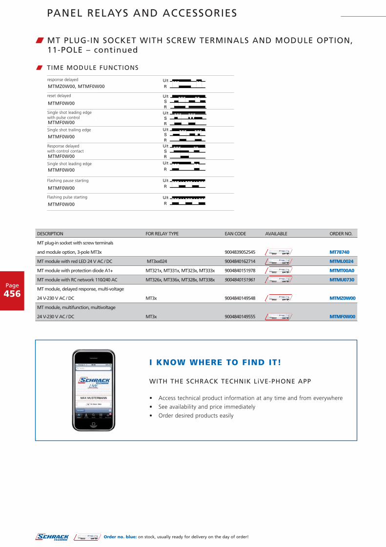
W MT PLUG-IN SOCKET WITH SCREW TERMINALS AND MODULE OPTION,11-POLE
w DIMENSIONS (mm)
Rated voltage 24...240 V∼ / V∼
Mains frequency 48...63 Hz
Repeat accuracy ± 0.5 %
Repeatability < 0.5 % or 5 ms
Temperature influence < 0.1 %/°C
Time ranges switchable 0.05 s...240 h in 8 ranges
Ambient temperature -25...+55 °C
w TECHNICAL DATA OF THE FUNCTION MODULES
3-pole
PANEL RELAYS AND ACCESSORIES
Page
456
ansprechverzögert
rückfallverzögert
einschaltwischendmit Impulsansteuerung
ausschaltwischend
ansprechverzögertmit Steuerkontakt
einschaltwischend
blinkend pausebeginnend
blinkend impulsbeginnend
w TIME MODULE FUNCTIONS
MTMZ0W00, MTMF0W00
MTMF0W00
MTMF0W00
MTMF0W00
MTMF0W00
MTMF0W00
MTMF0W00
MTMF0W00
DESCRIPTION FOR RELAY TYPE EAN CODE AVAILABLE ORDER NO.
MT plug-in socket with screw terminals
and module option, 3-pole MT3x 9004839052545 MT78740
MT module with red LED 24 V AC / DC MT3xx024 9004840162714 MTML0024
MT module with protection diode A1+ MT321x, MT331x, MT323x, MT333x 9004840151978 MTMT00A0
MT module with RC network 110/240 AC MT326x, MT336x, MT328x, MT338x 9004840151961 MTMU0730
MT module, delayed response, multi-voltage
24 V-230 V AC / DC MT3x 9004840149548 MTMZ0W00
MT module, multifunction, multivoltage
24 V-230 V AC / DC MT3x 9004840149555 MTMF0W00
I KNOW WHERE TO FIND IT!
WITH THE SCHRACK TECHNIK LiVE-PHONE APP
• Access technical product information at any time and from everywhere
• See availability and price immediately
• Order desired products easily
response delayed
reset delayed
Single shot leading edge with pulse control
Single shot trailing edge
Single shot leading edge
Flashing pause starting
Flashing pulse starting
Response delayed with control contact
Order no. blue: on stock, usually ready for delivery on the day of order!
W MT PLUG-IN SOCKET WITH SCREW TERMINALS AND MODULE OPTION,11-POLE – continued

PANEL RELAYS AND ACCESSORIES
Page
457
RM
W POWER RELAY RM
W SCHRACK-INFORM 2 / 3 / 7• 2 / 3-pole 10 / 16 A, DC and AC coil• Switching capacity up to 6000 VA• DC and AC coil• Mechanical indicator• Test button• Plug-in or PCB mountable, fixing with tongue,
DIN rail mounting• For lift control systems, power supplies
RM 6• 3-pole 10 / 16 A, DC and AC coil• 2 NO contact or 3 NO contacts• 3 mm contact gap• DC and AC coil• Test button• Plug-in or PCB mountable, fixing with tongue,
DIN rail mounting• For power adapters, power supplies, pump controllers
RM 8• 2-pole 25 A, DC and AC coil• 2 CO contacts• DC and AC coil• Mechanical indicator• Test button• Fastening with tongue or DIN rail mounting• For cleaning machines, heating / cooling units
RMD• 1-pole, 30 A, DC and AC coil• 1 NO or 1 NO + 1 NC contact• Switching capacity up to 7500 VA• DC and AC coil• Test button• Fastening with tongue• For battery chargers, heating controls
3 Wechsler
2 Wechsler
2 Wechsler
w CIRCUIT DIAGRAMS
RM 2 / 3 / 73 Schließer
RM 6 RM 81 Schließer, RMD
RMD
RM
3 CO
2 CO
2 CO3 NO 1 NO, RMD

PANEL RELAYS AND ACCESSORIES
Page
458
Kappe ohne Lasche, Steckanschlüsse Printversion
Kappe mit Befestigungslasche, Faston 250 (187 möglich) Kappe mit DIN-Schnappvorrichtung (nur Faston 250)liegend stehend
S0298-AC S0298-AE
S0298-ABS0298-AA
S0298-AD
w DIMENSIONS (mm)
Type
Kontakte
2 2 Wechsler, 16 A3 3 Wechsler, 10 A5 2 Schließer, 16 A (3 mm Kontaktabstand)6 3 Schließer, 10 A (3 mm Kontaktabstand)8 2 Wechsler, 25 AD 1 Schließer, 30 A (Brückenkontakt)
Kontakte
2 Kappe ohne Lasche, AMP-Faston 1873 Kappe mit Lasche, AMP-Faston 1875 Kappe mit Lasche, AMP-Faston 2507 Printversion8 Kappe mit DIN-Schnappvorrichtung, liegend, AMP-Faston 2509 Kappe mit DIN-Schnappvorrichtung, stehend, AMP-Faston 250
Bauart
Spulencode
AMP-Faston 187 = 4,8 x 0,5 mm AMP-Faston 250 = 6,3 x 0,8 mm
Spulencode siehe Spulentabelle; Vorzugstypen in Fettdruck
0 Ohne Prüftaste
7 3 Wechsler, 16 A
3 Mit Prüftaste
R M
RM 2, 3, 7 RM 6 RM 8
w LOAD BREAKING CAPACITY
RMD
Cover without lug, plug-in connectors for plug-in socket
Cap with mounting bracket, Faston 250 (187 possible) Cap with DIN snap mechanism (only Faston 250)lying standing
Max. DC load breaking capacity Max. DC load breaking capacity Max. DC load breaking capacity Max. DC load breaking capacity
DC
vol
tage
[V
DC
]
DC
vol
tage
[V
DC
]
DC
vol
tage
[V
DC
]
DC
vol
tage
[V
DC
]
DC current [A] DC current [A] DC current [A] DC current [A]
Resistive load
Resistive load
Resistive load Resistive load
3 contacts in series
3 contacts in
2 contacts in series2 contacts in series
2 contacts in series
1 contact
1 contact 1 contact
Type
Contacts
Version
Contacts
Coil code
AMP Faston 187 = 4.8 x 0.5 mm AMP Faston 250 = 6.3 x 0.8 mm
Coil code: please see coil table, preferred types in bold print
Without test button
Cap without lug, AMP Faston 187Cap with lug, AMP Faston 187Cap with lug, AMP Faston 250
Cap with DIN snap mechanism, lying, AMP Faston 250Cap with DIN snap mechanism, standing, AMP Faston 250
With test button
2 CO, 16 A 3 CO, 16 A3 CO, 10 A
3 NO, 10 A (3 mm contact gap)2 CO, 25 A1 NO, 30 A (bridging contact)
W POWER RELAY RM – continued
w TYPE KEY

PANEL RELAYS AND ACCESSORIES
Page
459
W POWER RELAY RM – continued
CONTACT DATA RM2 RM3 RM7
Number of contacts and type 2 CO 3 CO 3 CO
Contact version Single contact Single contact Single contact
Rated current 16 A 10 A 16 A
Rated voltage / max. switching voltage AC 380 V∼ / 440 V∼ 380 V∼ / 440 V∼ 380 V∼ / 440 V∼
Max. breaking capacity AC 6000 VA 3800 VA 6000 VA
Making capacity (max. 4 s at 10% DF) 40 A 40 A 40 A
Contact material AgCdO AgCdO AgCdO
COIL DATA
Rated voltage range DC coil 12...24 VDC 24 VDC 12...60 VDC
AC coil 230 VAC 230 VAC 24...400 VDC
Rated output DC coil 1.2 W 1.2 W 1.6 W
AC coil 2.3 VA 2.3 VA 2.8 VA
Operation release voltage/coil resistance 24 VDC coil 18 V / 2.4 V 18 V / 2.4 V 18 V / 2.4 V
at ambient temperature 23 °C 230 VAC coil 184 V / 92 V 184 V / 92 V 184 V / 92 V
Visit www.schrack.com for further technical data
w TECHNICAL DATA
CONTACT DATA RM6 RM8
Number of contacts and type 3 NO 2 CO
Contact version Single contact Single contact
Rated current 10 A 25 A
Rated voltage / max. switching voltage AC 380 V∼ / 440 V∼ 250 V∼ / 440 V∼
Max. breaking capacity AC 3800 VA 6000 VA
Making capacity (max. 4 s at 10% DF) 25 A 60 A
Contact material AgCdO AgCdO
COIL DATA
Rated voltage range DC coil 24 VDC 24 VDC
AC coil 230 VAC 230 VAC
Rated output DC coil 1.6 W 1.2 W
AC coil 2.8 VA 2.8 VA
Operation release voltage/coil resistance 24 VDC coil 18 V / 2.4 V 18 V / 2.4 V
at ambient temperature 23 °C 230 VAC coil 184 V / 92 V 184 V / 92 V
Visit www.schrack.com for further technical data
CONTACT DATA RMD
Number of contacts and type 1 NO contact
Contact version Bridge context
Rated current 30 A
Rated voltage / max. switching voltage AC 250 V∼ / 440 V∼
Max. breaking capacity AC 7500 VA
Making capacity (max. 4 s at 10% DF) 60 A
Contact material AgCdO
COIL DATA
Rated voltage range DC coil 6...220 VDC
AC coil 6...400 VAC
Rated output DC coil 24 VDC
Operation release voltage/coil resistance 24 VDC coil 18 V / 2.4 V
at ambient temperature 23 °C 230 VAC coil 184 V / 92 V
Visit www.schrack.com for further technical data

PANEL RELAYS AND ACCESSORIES
Page
460
CONTACTS COIL CONTACT MAT. TYPE EAN CODE AVAILABLE ORDER NO.
10 A
3 CO, (for RM socket) 24 V DC AgCdO SREL-SL-3-UKE-M1-024G-10 9004840105346 RM332024-D
3 CO, (for RM socket)
without test button 24 V DC AgCdO SREL-SL-3-UKE-M1-024G-10 9004840110319 RM302024-D
3 CO, (for RM socket) 230 V AC AgCdO SREL-SL-3-UKE-M1-230W-10 9004840105353 RM3327305E
3 NO, 3 mm
(for RM socket) 24 V DC AgCdO SREL-SL-3-AKE-M1-024G-10 9004840101478 RM632024-A
3 NO, (for RM socket) 24 V DC AgCdO SREL-SL-3-AKE-M1-024G-10 9004840125238 RM602024
3 NO, (for RM socket) 24 V DC AgCdO SREL-SL-3-UKE-M1-024G-10 9004840101478 RM632024-A
16 A
2 CO, (for RM socket) 24 V DC AgCdO SREL-SL-2-UKE-M1-024G-10 9004840109955 RM232024-D
3 CO, (for RM socket) 12 V DC AgCdO SREL-SL-3-UKE-M1-012G-16 9004840105513 RM732012-C
3 CO, (for RM socket) 24 V DC AgCdO SREL-SL-3-UKE-M1-024G-16 9004840105360 RM732024-C
3 CO, (for RM socket)
without test button 24 V DC AgCdO SREL-SL-3-UKE-M1-024G-16 9004840105384 RM702024-C
3 CO, (for RM socket) 60 V DC AgCdO SREL-SL-3-UKE-M1-060G-16 9004840101225 RM732060
3 CO, (for RM socket) 24 V AC AgCdO SREL-SL-3-UKE-M1-024W-16 9004840104233 RM732524-C
3 CO, (for RM socket) 230 V AC AgCdO SREL-SL-3-UKE-M1-230W-16 9004839086984 RM732730
3 CO 230 V AC AgCdO SREL-SL-3-UKE-M1-230W-16 9004840103786 RM7357305E
3 CO 400 V AC AgCdO SREL-SL-3-UKE-M1-400W-16 9004840385113 RM732900
3 CO 24 V DC AgCdO SREL-LL-3-UKE-M1-024G-16 9004840103816 RM738024-C
3 CO 230 V AC AgCdO SREL-LL-3-UKE-M1-230W-16 9004840103854 RM738730-C
3 CO 230 V AC AgCdO SREL-SL-3-UKE-M1-230W-16 9004840100020 RM7397305E
25 A
2 CO 24 V DC AgCdO SREL-SL-2-UKE-M1-024G-25 9004840104264 RM835024
2 CO 24 V DC AgCdO SREL-LL-2-UKE-M1-024G-25 9004840100037 RM838024
2 CO 24 V DC AgCdO SREL-SL-2-UKE-M1-024G-25 9004840104042 RM839024
2 CO 230 V AC AgCdO SREL-SL-2-UKE-M1-230W-25 9004840105742 RM805730
2 CO 230 V AC AgCdO SREL-SL-2-UKE-M1-230W-25 9004840142815 RM809730
2 CO 230 V AC AgCdO SREL-SL-2-UKE-M1-230W-25 9004840100938 RM8357305E
2 CO 230 V AC AgCdO SREL-SL-2-UKE-M1-230W-25 9004840111149 RM839730
30 A
3 NO 24 V DC AgCdO LEIST-REL-GS-BRK-30A 9004840189087 RMD05024
Order no. blue: on stock, usually ready for delivery on the day of order!
W POWER RELAY RM – continued
I KNOW WHERE TO FIND IT!
THE SCHRACK TECHNIK WEB SHOP WITH NAVIGATORWWW.SCHRACK.COM
• Finding product information made easy
• Buying products around the clock
• Quick access customer service

PANEL RELAYS AND ACCESSORIES
Page
461
Order no. blue: on stock, usually ready for delivery on the day of order!
W ACCESSORIES FOR POWER RELAYS RM – GENERAL INFORMATION
W SCHRACK-INFO• 2 / 3-pole, 10 / 16 A• suitable, e.g.. for the relays: RM332, RM632, RM732
UP TO 250 V AC
Rated current 16 A
Rated voltage / max. switching voltage 250 V∼
Dielectric strength coil / contact set > 2500 Ve
Ambient temperature -40...+40 °C
Terminal torque 0.8 Nm
max. 1.2 Nm
w TECHNICAL DATA
W RM PLUG-IN SOCKET WITH SCREW TERMINALS
S0317-A
w DIMENSIONS (mm)RM78705
RM ACCESORIES
RM78705
DESCRIPTION FOR RELAY TYPE EAN CODE AVAILABLE ORDER NO.
RM-socket for screw fastening up to 250 V AC RMxx2x (187 Faston) 9004839013621 RM78705

PCB RELAYS
Page
462
CONTACTS COIL CONTACT MAT. TYPE EAN CODE AVAILABLE ORDER NO.
1 CO, 5 A 5 V DC AgNi 90/10 PREL-SL-1-UKE-M1-005G-05 9004840158632 PE014005
1 CO, 5 A 12 V DC AgNi 90/10 PREL-SL-1-UKE-M1-012G-05 9004840160598 PE014012
CONTACTS COIL CONTACT MAT. TYPE EAN CODE AVAILABLE ORDER NO.
1 NO, 6 A 5 V DC AgCdO PREL-SW-1-AKE-M1-005G-06 9004840159110 RE030005
1 NO, 6 A 12 V DC AgCdO PREL-SW-1-AKE-M1-012G-06 9004840155167 RE030012
1 NO, 6 A 24 V DC AgCdO PREL-SW-1-AKE-M1-024G-06 9004839000270 RE030024
W PCB RELAYS PE / PE BISTABLEW SCHRACK-INFO
• 1 CO or 1 NO contact, 5 A• Coil 3 to 48 V DC monostable or bistable• Nominal coil power: 200 mW • For industrial electronics, domestic
appliances, battery-powered equipment• Technical data at www.schrack.com
W MINIATURE PCB RELAYS REW SCHRACK-INFO
• 1 NO contact, 6 A• Coil 5 to 48 V DC • Nominal coil power: 200 mW • For PLCs, timer relays, temperature controllers,
interface cards, domestic appliances• Technical data at www.schrack.com
CONTACTS COIL CONTACT MAT. TYPE EAN CODE AVAILABLE ORDER NO.
1 CO, 6 A 12 V DC AgSnO PREL-SW-1-UKE-M1-012G-06-5.0 9004840240535 SNR03012
1 CO, 6 A 24 V DC AgSnO PREL-SW-1-UKE-M1-024G-06-5.0 9004840175097 SNR03024
1 NO, 6 A 24 V DC AgSnO PREL-SW-1-AKE-M1-024G-06-5.0 9004840177299 SNR13024
W SLIM PCB RELAY SNR W SCHRACK-INFO
• 1 CO or 1 NO contact, 6 A• Coil 5 to 60 V DC • Nominal coil power: 170 mW • For heating control, narrowestcoupling
elements, interface applications, PLC, I/O modules
• Technical data at www.schrack.com
Order no. blue: on stock, usually ready for delivery on the day of order!

PCB RELAYS
Page
463
Order no. blue: on stock, usually ready for delivery on the day of order!
W PCB RELAY RY IIW SCHRACK-INFO
• Pinning 5 mm• 1 CO, NO or NC contact, 8 A• Coil 5 to 60 V DC • Nominal coil power: 220 mW • for heating controls, timer relays, timers• Technical data at www.schrack.com
CONTACTS PINNING COIL EAN-CODE AVAILABLE ORDER NO.
1 CO, 8 A 12 V DC 9004840158212 RY210012
1 CO, 8 A 24 V DC 9004840155112 RY210024
1 NO, 8 A 12 V DC 9004840185867 RY530012
1 CO, 8 A 24 V DC 9004840156126 RY612024
3.2 mm
3.2 mm
5 mm
3.2 mm
W POWER RELAYS RT W SCHRACK-INFO
• 1 and 2 CO or NO contacts, 8/12/16 A• Coil 5 to 110 V DC, 24 to 230 V AC • Monostable and bistable • Inrush, sensitive and high-temperature• Pinning 3.5 and 5 mm• Universal application• Technical data at www.schrack.com
CONTACTS PINNING COIL EAN-CODE AVAILABLE ORDER NO.
2 CO, 8 A 5 mm 6 V DC 9004840158939 RT424006
2 CO, 8 A 5 mm 12 V DC 9004839019241 RT424012
2 CO, 8 A 5 mm 24 V DC 9004839019142 RT424024
2 CO, 8 A 5 mm 48 V DC 9004839027185 RT424048
2 CO, 8 A 5 mm 60 V DC 9004840193558 RT424060
2 CO, 8 A 5 mm 110 V DC 9004840191561 RT424110
2 CO, 8 A 5 mm 24 V AC 9004839034602 RT424524
2 CO, 8 A 5 mm 48 V AC 9004840167641 RT424548
2 CO, 8 A 5 mm 115 V AC 9004840158021 RT424615
2 CO, 8 A 5 mm 230 V AC 9004839034282 RT424730
2 CO, 8 A 5 mm 5 V DC - bistable 9004840166491 RT424A05
2 CO, 8 A 5 mm 24 V DC - bistable 9004840193572 RT424A24
2 CO, 8 A 5 mm 12 V DC - bistable 9004840158205 RT424F12
2 CO, 8 A 5 mm 24 V DC - bistable 9004840160864 RT424F24
2 CO, 8 A 5 mm 24 V DC 9004840160628 RT425024
2 CO, 8 A 5 mm 115 V AC 9004840187748 RT425615
2 CO, 8 A 5 mm 230 V AC 9004840166040 RT425730
2 CO, 8 A 5 mm 24 V DC 9004839029103 RTE24024

PCB RELAYS
Page
464
W OTHER PCB RELAYS
W SCHRACK-INFO• RP 2• Card relay E (RP 1, V23057)
CONTACTS PINNING COIL EAN-CODE AVAILABLE ORDER NO.
1 CO, 16 A 12 V DC 9004840155181 RP310012-A
1 CO, 16 A 24 V DC 9004840166033 RP310024-A
1 CO, 8 A 24 V DC 9004840155235 RP418024-A
2 CO, 8 A 12 V DC 9004840155242 RP420012-B
2 CO, 8 A 24 V DC 9004840155259 RP420024-B
2 CO, 8 A 24 V AC 9004840189964 RP420524-B
2 CO, 8 A 230 V AC 9004840189988 RP420730-B
2 CO, 8 A 24 V DC 9004840157970 RP421024-B
2 CO, 8 A 48 V DC 9004840160581 RP421048-B
1 CO, 8 A 12 V DC 9004840166910 RP510012-E
1 CO, 8 A 24 V DC 9004840165029 RP510024-E
1 CO, 8 A 60 V DC 9004840231175 RP510060-E
1 NO, 8 A 24 V DC 9004840180107 RP531024-H
1 CO, 8 A 5 V DC 9004840160840 RP610005-E
1 CO, 8 A 12 V DC 9004840172720 RP610012-E
1 CO, 8 A 24 V DC 9004840165012 RP611024-E
1 CO, 16 A 24 V DC 9004840185508 RP710024-A
2 CO, 8 A 24 V DC 9004840185546 RP820024-A
2 CO, 8 A 24 V DC 9004840169720 RP821024-A
1 NO, 10 A 24 V DC 9004840161427 RTH84024
5 mm
5 mm
3.5 mm
5 mm
5 mm
5 mm
5 mm
5 mm
5 mm
2.5 mm
2.5 mm
2.5 mm
2.5 mm
2.5 mm
2.5 mm
2.5 mm
5 mm
5 mm
5 mm
5 mm
Order no. blue: on stock, usually ready for delivery on the day of order!
I KNOW WHERE TO FIND IT!
WITH THE SCHRACK TECHNIK LiVE-PHONE APP
• Access technical product information at any time and from everywhere
• See availability and price immediately
• Order desired products easily

Order no. blue: on stock, usually ready for delivery on the day of order!
Page
465
PCB RELAYS
W SOCKETS FOR PCB CONNECTION
RP78601 RT16041
DESCRIPTION EAN CODE AVAILABLE ORDER NO.
SOCKET
PCB socket for PCB relay with 3.5 mm pinning 9004840157888 RP78601
PCB socket for PCB relay with 5.0 mm pinning 9004840100518 RP78602
ACCESSORIES
Retaining clip for RT relay 9004840167764 RT16041
Retaining clip for RT PCB socket, metal 9004840191578 RT28516
w DIMENSIONS (mm)
PT78600 PT78604
W PT SOCKETS WITH SOLDER/PCB TERMINALS
W SCHRACK-INFO• Rated current: 10 A
• Rated voltage: 250 V~
• Dielectric strength peak/cont.: >1500 Veff
• Ambient temperature: -40...+70 °C
Plug-in socket with solder terminals, 4-pole PT78600
Mounting plate recess
DESCRIPTION PU EAN CODE AVAILABLE ORDER NO.
PT SOCKET WITH SOLDER/PCB TERMINALS
Plug-in socket with PCB terminals, 4-pole, 6 A 100 9004840226829 PT78604
Plug-in socket with PCB terminals, 3-pole, 10 A 100 9004840153996 PT78603
ACCESSORIES FOR PT SOCKETS
Retaining clip for PCB socket, metal 10 9004840154108 PT28802
Plug-in sockets with PCB terminals PT78602/03/04

PCB RELAYS
Page
466
Order no. blue: on stock, usually ready for delivery on the day of order!
W MT PLUG-IN BASES WITH SOLDER-PINS
MT78603
W SCHRACK-INFO• Rated current 10 A
• Rated voltage 250 V~
• Dielectric strength peak/cont. >2500 Veff
• Ambient temperature -40...+70 °C
Plug-in sockets 11-pole with PCB terminals MT787 603
w DIMENSIONS (mm)
DESCRIPTION WxHxD (mm) PU EAN CODE AVAILABLE ORDER NO.
11-pole plug-in socket with PCB terminal Ø 28x19 25 9004840226881 MT78603
I KNOW WHERE TO FIND IT!
THE SCHRACK TECHNIK WEB SHOP WITH NAVIGATORWWW.SCHRACK.COM
• Finding product information made easy
• Buying products around the clock
• Quick access customer service

FORCE GUIDED RELAYS
Page
467
W RELAY WITH FORCE GUIDED CONTACTS SR4D/M
W SCHRACK-INFO• 3 NO, 1 NC or 2 NO, 2 NC, 8 A• Coil 5 to 110 V DC • Technical data at www.schrack.com
W RELAY WITH FORCE GUIDED CONTACTS SR6
W SCHRACK-INFO• 4 NO, 2 NC, 8 A• 3 NO, 3 NC, 8 A• 5 NO, 1 NC, 8 A• Coil 5 to 110 V DC • Technical data at www.schrack.com
CONTACTS PINNING COIL EAN-CODE AVAILABLE ORDER NO.
1 NO, 6 A 5 mm 24 V DC 9004840378269 SR2X5024
2 CO, 6 A 5 mm 24 V DC 9004840226713 SR2Y5024
CONTACTS COIL EAN-CODE AVAILABLE ORDER NO.
2 NO, 2 NC, 6 A 24 V DC 9004840226720 SR4D4024
3 NO, 1 NC, 8 A 24 V DC 9004840373219 SR4M4024
I KNOW WHERE TO FIND IT!
WITH THE SCHRACK TECHNIK LiVE-PHONE APP
• Access technical product information at any time and from everywhere
• See availability and price immediately
• Order desired products easily
Order no. blue: on stock, usually ready for delivery on the day of order!

FORCE GUIDED RELAYS
Page
468
W RELAY WITH FORCE GUIDED CONTACTS SR2Z
W SCHRACK-INFO• 2-pole 6 A• 2 CO, 6 A• Coil 24 V DC • SR2 on DIN rail module• Screwless terminals
w DIMENSIONS (mm) w CIRCUIT DIAGRAM
W TYPE KEY
Type
Contacts
Y 2 CO
Coil
DC coil code = nominal voltage (z. B. 024 = 24 V∼)
S R 20 42 Z Y
SR2Z

FORCE GUIDED RELAYS
Page
469
CONTACT DATA
Contact type Single contact, positive action
Rated current 6 A
Rated voltage / max. switching voltage AC 250 V∼ / V =
Max. breaking capacity AC 1500 VA
Contact material AgNi
Recommended minimum load > 10 mA / 5 V
INSOLATION
Initial dielectric strength between Coil and contacts 4000 Veff
Open contact circuit 1000 Veff
Adjacent contacts 2000 Veff
Clearance/Creepage between Coil and contacts 8 / 8 mm
Adjacent contacts 3 / 3 mm
Insulation to IEC 50178 between
Coil and contacts Reinforced
Adjacent contacts Basic
OTHER DATA
Ambient temperature -25...+50 °C
Mechanical endurance > 10x106 operations
Max. switching frequency with/without load 6 min-1 / 300 min-1
Terminal cross section (according to IEC)
Copper wire 0.2...2.5 mm²
Stranded wire 0.2...2.5 mm²
AWG 28...14
Installation position Any
Mounting On DIN rail without gap
Connection Screwless terminals
w TECHNICAL DATA
CONTACTS COIL EAN-CODE AVAILABLE ORDER NO.
4 NO, 2 NC, 8 A 24 V DC 9004840251517 SR6B4024
Order no. blue: on stock, usually ready for delivery on the day of order!
I KNOW WHERE TO FIND IT!
THE SCHRACK TECHNIK WEB SHOP WITH NAVIGATORWWW.SCHRACK.COM
• Finding product information made easy
• Buying products around the clock
• Quick access customer service

FORCE GUIDED RELAYS
Page
470
W RELAY WITH FORCE GUIDED CONTACTS SR6Z
W SCHRACK-INFO• 6-pole 8 A• 4 NO, 2 NC, 8 A• Coil 24 VDC • SR6 on DIN rail module• Screwless terminals• Module width 46 mm• For lift and escalator control, machine control
w DIMENSIONS (mm)
S R 6 ZTypenschlüssel
Kontakte
A =3 Schließer und 3 Öffner
B =4 Schließer und 2 Öffner
C =5 Schließer und 1 Öffner
Type
Spule
DC Spulencode = Nennspannung (z.B. 024 = Vd
AC/DC Spulencode: 524 = 24Va/Vd, 615 = 115Va/Vd
AC Spulencode: 730 = 230Va
Spulencode siehe Spulentabelle
Andere Typen auf Anfrage
w TYPE KEY
Module width 46 mm, module length 87 mm
Suitable for mounting rails according
to DIN EN 50022 or DIN EN 50035
SR6Z
Contacts
CoilDC coil code = nominal voltage (e.g. 024 = V )
Other types available on request
4 NO and 2 NC

FORCE GUIDED RELAYS
Page
471
CONTACT DATA
Contact type Single contact, positive action
Rated current 8 A
Rated voltage / max. switching voltage AC 250 V∼ / V =
Max. breaking capacity AC 2000 VA
Contact material AgSnO
Recommended minimum load > 50 mW
INSOLATION
Initial dielectric strength between Coil and contacts 3000 Veff
Open contact circuit 1000 Veff
Adjacent contacts 3000 Veff
Clearance/Creepage between Coil and contacts 5.5 / 5.5 mm
Adjacent contacts 3 / 3 mm
Insulation to IEC 50178 between
Coil and contacts Reinforced
Adjacent contacts Basic
OTHER DATA
Ambient temperature -25...+50 °C
Mechanical endurance > 10x106 operations
Max. switching frequency with/without load 6 min-1 / 300 min-1
Terminal cross section (according to IEC)
Copper wire 0.2...2.5 mm²
Stranded wire 0.2...2.5 mm²
AWG 28...14
Installation position Any
Mounting On DIN rail without gap
Connection Screwless terminals
w TECHNICAL DATA
CONTACTS COIL TYPE EAN-CODE AVAILABLE ORDER NO.
2 CO, 6 A 24 V DC PREL-BG-2UKE-M1-024G-06-DIN 9004840537185 SR2ZY024
I KNOW WHERE TO FIND IT!
WITH THE SCHRACK TECHNIK LiVE-PHONE APP
• Access technical product information at any time and from everywhere
• See availability and price immediately
• Order desired products easily
Order no. blue: on stock, usually ready for delivery on the day of order!

MODULAR RELAYS
Page
472
W COUPLING RELAY FOR DIN-RAIL
W SCHRACK-INFO• Modular relay• 1 CO or 2 CO• Width 35 mm• Installation design• Low noise
BZ652000
35mm 44mm
60mm
5mm
87m
m
45m
m
w DIMENSIONS (mm)
U
R
w FUNCTIONAL DESCRIPTION
A1
11
A2 12 14
A1
R
12
U ~(+)
(-)
21
22 24
R
22 24
2111
A2
14
w CIRCUIT DIAGRAM

MODULAR RELAYS
Page
473
W TECHNICAL DATA
FUNCTIONS
Coupling relay
INDICATORS
Yellow LED R ON/OFF Position of output relay
MECHANICAL DESIGN
Housing made of self-extinguishing plastic, degree of protection IP40
Mounting on DIN rail TS 35 according to EN 60715
Installation position Any
Touch-proof clamping yoke terminals according to VBG 4
(PZ1 required), degree of protection IP20
Tightening torque Max 1 Nm
Terminal capacity 1 x 0.5 to 2.5 mm² with/without ferrule
1 x 4 mm² without ferrule
2 x 0.5 to 1.5 mm² with/without ferrules
2 x 2.5 mm² flexible with/without ferrules
INPUT CIRCUIT
Supply voltage 12 to 240 V~/DC (2 CO) and 24 to 240 V~/DC (1 CO)
Terminals A1(+)-A2
Tolerance -10% to +10%
Rated consumption 6 VA (2 W)
Rated frequency AC 48 to 63 Hz
Duty cycle 100%
Recovery time 100 ms
Residual ripple for DC 10%
Drop-out voltage >30% of min supply voltage
Overvoltage category III (according to IEC 60664-1)
Rated surge voltage 4kV
OUTPUT CIRCUIT
1 or 2 potential-free changeover switches
Rated voltage 250 V~
Switching capacity 2000 VA (8 A / 250 V)
Fuse 8A fast acting
Mechanical endurance 20 x 106 operations
Electrical endurance 2 x 10⁵ operations at 1000 VA resistive load
Switching frequency Max. 6/min at 1000 VA resistive load (according to IEC 60947-5-1)
Overvoltage category III (according to IEC 60664-1)
Rated surge voltage 4 kV
AMBIENT CONDITIONS
Ambient temperature -25 to +55 °C
Relative humidity 15% to 85% (according to IEC 60721-3-3 class 3K3)
Pollution degree 2, when built-in 3 (according to IEC 60664-1)
WEIGHT
Individual packaging 100g
DESCRIPTION EAN CODE AVAILABLE ORDER NO.
Modular relay, 1 CO, 24-240 V~/DC 9004840557381 BZ651000
Modular relay, 2 CO, 12-240 V~/DC 9004840557473 BZ652000
Order no. blue: on stock, usually ready for delivery on the day of order!

TIME- AND MONITORING RELAYS
Page
474
W TIME- AND MONITORING RELAYS

TIME- AND MONITORING RELAYS
Page
475
W MEASURING AND MONITORING RELAYS
W SERIES 5
W SERIES 6
OPERATION DISPLAY
LARGE TIME RANGE 50 ms – 100 h
MANY FUNCTIONS
45 mm CAP DIMENSION
MULTI-VOLTAGE 12 or 24 V~/DC – 240 V~/DC
INDUSTRIAL DESIGN
WIDTH 22.5 mm
MANY FUNCTIONS, E.G.:
• Monitoring of phase sequence and phase failure
• Detection of neutral wire break
• Windows function
• 16.6 – 400 Hz
• Thermal resistor relay
• Delayed contacts possible
• Time range of timer relay: 1 s to 30 days

TIME RELAYS
Page
476
Types ZR5..24-240 V AC/DC: 24 to 240 V AC/DCTolerance: 24 V-15% to 240 V+10%
Rated consumption: 4 VA (1.5 W)Rated frequency: AC 48 to 63 Hz
2. Time rangesTime range Adjustment range
1 s 50 ms 1 s10 s 500 ms 10 s
1 min 3 s 1 min 10 min 30 s 10 min
1 h 3 min 1 h10 h 30 min 10 h
100 h 5 h 100 h
3. IndicatorsGreen LED U/t ON: indication of supply voltageGreen LED U/t flashes: indication of time periodYellow LED R ON/OFF: indication of relay outputs
4. Mechanical designSelf-extinguishing plastic housing, IP rating IP40Mounted on DIN-rail TS 35 according to EN 50022Mounting position: anyShockproof terminal connection according to VBG 4 (PZ1 required), IP rating IP20Tightening torque: max. 1 NmTerminal capacity:
1 x 0.5 to 2.5 mm² with/without multicore cable end1 x 4 mm² without multicore cable end2 x 0.5 to 1.5 mm² with/without multicore cable end2 x 2.5 mm² flexible without multicore cable end
5. Input circuitSupply voltage: Terminals A1(+)-A2
1. FunctionsThe function has to be set before connecting the relay to the supply voltage.E ON delay
6. Output circuit1 potential free change over contactRated voltage: 250 V ACSwitching capacity: 2000 VA (8 A / 250V)Fusing: 8 A fast actingMechanical life: 20 x 106 operationsElectrical life: 2 x 10⁵ operations
at 1000 VA resistive loadSwitching frequency: max. 60/min at 100 VA resistive load
max. 6/min at 1000 VA resistive load(according to IEC 947-5-1)
Overvoltage category: III. (according to IEC 60664-1)Rated surge voltage: 4 kV
7. Control inputInput not potential free: Terminals A1-B1Loadable: yesMax. line length: 10mTrigger level (sensitivity): automatic adaption to supply
voltageMin. control pulse length: DC 50 ms / AC 100 ms
8. AccuracyBase accuracy: ±1% of maximum scale valueAdjustment accuracy: <5% of maximum scale valueRepetition accuracy: <0.5% or ±5 msVoltage influence: -Temperature influence: �0.01% / °C
9. Ambient conditionsAmbient temperature: -25 to +55 °C
(according to IEC 68-1)Storage temperature: -25 to +70 °CTransport temperature: -25 to +70 °CRelative humidity: 15% to 85%
(according to IEC 721-3-3 class 3K3)Pollution degree: 2, if built in 3
(according to IEC 664-1)Vibration resistance: 10 to 55 Hz 0.35 mm
(according to IEC 68-2-6)Shock resistance: 15 g 11 ms
(according to IEC 68-2-27)Duty cycle: 100%Reset time: 100 msResidual ripple for DC: 10%Drop-out voltage: >30% of minimum rated supply
voltageOvervoltage category: III (according to IEC 60664-1)Rated surge voltage: 4 kV
Wide input voltage range 1 change over contact Width 17,5 mm Installation design
w TECHNICAL DATA
w SCHRACK-INFO
w TIME RELAY ZR5E0011

TIME RELAYS
Page
477
Order no. blue: on stock, usually ready for delivery on the day of order!
ON delay (E)When the supply voltage U is applied, the set interval t begins (green LEDU/t flashes). After the interval t has expired (green LED U/t illuminated)the output relay R switches into on-position (yellow LED illuminated). Thisstatus remains until the supply voltage is interrupted. If the supply voltage isinterrupted before the expiry of the interval t, the interval already expiredis erased and is restarted when the supply voltage is next applied.
Single packing: 72 gPackage 10 pcs: 670 g per Package
w FUNCTIONS w CONNECTIONS
w DIMENSIONSw WEIGHT
W ARTICLE NUMBER
DESCRIPTION ORDER NO.
Single function timerelay E (ON delay),
24-240VAC, 1 change over, 8A/250V ZR5E0011
without control input
DESCRIPTION EAN CODE AVAILABLE ORDER NO.
Single function time relay E (ON delay), 24-240VAC, 1 change over, 8A/250V 9004840459029 ZR5E0011
I KNOW WHERE TO FIND IT!
THE SCHRACK TECHNIK WEB SHOP WITH NAVIGATORWWW.SCHRACK.COM
• Finding product information made easy
• Buying products around the clock
• Quick access customer service

TIME RELAYS
Page
478
Types ZR5..24-240 V AC/DC: 24 to 240 V AC/DCTolerance: 24 V-15% to 240 V+10%
Rated consumption: 4 VA (1.5 W)Rated frequency: AC 48 to 63 Hz
2. Time rangesTime range Adjustment range
1 s 50 ms 1 s10 s 500 ms 10 s
1 min 3 s 1 min 10 min 30 s 10 min
1 h 3 min 1 h10 h 30 min 10 h
100 h 5 h 100 h
3. IndicatorsGreen LED U/t ON: indication of supply voltageGreen LED U/t flashes: indication of time periodYellow LED R ON/OFF: indication of relay outputs
4. Mechanical designSelf-extinguishing plastic housing, IP rating IP40Mounted on DIN-rail TS 35 according to EN 50022Mounting position: anyShockproof terminal connection according to VBG 4 (PZ1 required), IP rating IP20Tightening torque: max. 1 NmTerminal capacity:
1 x 0.5 to 2.5 mm² with/without multicore cable end1 x 4 mm² without multicore cable end2 x 0.5 to 1.5 mm² with/without multicore cable end2 x 2.5 mm² flexible without multicore cable end
5. Input circuitSupply voltage: Terminals A1(+)-A2
1. FunctionsThe function has to be set before connecting the relay to the supply voltage.R OFF delay
6. Output circuit1 potential free change over contactRated voltage: 250 V ACSwitching capacity: 2000 VA (8 A / 250V)Fusing: 8 A fast actingMechanical life: 20 x 106 operationsElectrical life: 2 x 10⁵ operations
at 1000 VA resistive loadSwitching frequency: max. 60/min at 100 VA resistive load
max. 6/min at 1000 VA resistive load(according to IEC 947-5-1)
Overvoltage category: III. (according to IEC 60664-1)Rated surge voltage: 4 kV
7. Control inputInput not potential free: Terminals A1-B1Loadable: yesMax. line length: 10mTrigger level (sensitivity): automatic adaption to supply
voltageMin. control pulse length: DC 50 ms / AC 100 ms
8. AccuracyBase accuracy: ±1% of maximum scale valueAdjustment accuracy: <5% of maximum scale valueRepetition accuracy: <0.5% or ±5 msVoltage influence: -Temperature influence: �0.01% / °C
9. Ambient conditionsAmbient temperature: -25 to +55 °C
(according to IEC 68-1)Storage temperature: -25 to +70 °CTransport temperature: -25 to +70 °CRelative humidity: 15% to 85%
(according to IEC 721-3-3 class 3K3)Pollution degree: 2, if built in 3
(according to IEC 664-1)Vibration resistance: 10 to 55 Hz 0.35 mm
(according to IEC 68-2-6)Shock resistance: 15 g 11 ms
(according to IEC 68-2-27)Duty cycle: 100%Reset time: 100 msResidual ripple for DC: 10%Drop-out voltage: >30% of minimum rated supply
voltageOvervoltage category: III (according to IEC 60664-1)Rated surge voltage: 4 kV
Wide input voltage range 1 change over contact Width 17,5 mm Installation design
w TECHNICAL DATA
w SCHRACK-INFO
w TIME RELAY ZR5R0011

TIME RELAYS
Page
479
Order no. blue: on stock, usually ready for delivery on the day of order!
OFF delay (R)The supply voltage U must be constantly applied to the device (greenLED U/t illuminated). When the control contact S is closed, the outputrelay R switches into on-position (yellow LED illuminated). If the control contact is opened, the set interval t begins (green LED flashes). After the interval t has expired (green LED U/t illuminated) theoutput relay switches into off-position (yellow LED not illuminated). Ifthe control contact is closed again before the interval t has expired, the interval already expired is erased and is restarted.
Single packing: 72 gPackage 10 pcs: 670 g per Package
w FUNCTIONS w CONNECTIONS
w DIMENSIONSw WEIGHT
W ARTICLE NUMBER
DESCRIPTION ORDER NO.
Single function timerelay R (OFF delay),
24-240VAC, 1 change over, 8A/250V ZR5R0011
with control input
DESCRIPTION EAN CODE AVAILABLE ORDER NO.
Single function time relay R (OFF delay), 24-240VAC, 1 change over, 8A/250V 9004840459050 ZR5R0011
I KNOW WHERE TO FIND IT!
WITH THE SCHRACK TECHNIK LiVE-PHONE APP
• Access technical product information at any time and from everywhere
• See availability and price immediately
• Order desired products easily
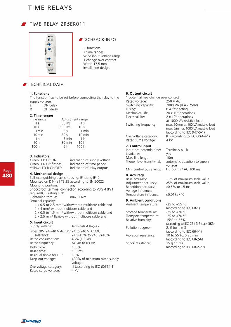
TIME RELAYS
Page
480
% %Types ZR5..24-240 V AC/DC: 24 to 240 V AC/DC
Tolerance: 24 V-15% to 240 V+10%Rated consumption: 4 VA (1.5 W)Rated frequency: AC 48 to 63 Hz
2. Time rangesTime range Adjustment range
1 s 50 ms 1 s10 s 500 ms 10 s
1 min 3 s 1 min 10 min 30 s 10 min
1 h 3 min 1 h10 h 30 min 10 h
100 h 5 h 100 h
3. IndicatorsGreen LED U/t ON: indication of supply voltageGreen LED U/t flashes: indication of time periodYellow LED R ON/OFF: indication of relay outputs
4. Mechanical designSelf-extinguishing plastic housing, IP rating IP40Mounted on DIN-rail TS 35 according to EN 50022Mounting position: anyShockproof terminal connection according to VBG 4 (PZ1 required), IP rating IP20Tightening torque: max. 1 NmTerminal capacity:
1 x 0.5 to 2.5 mm² with/without multicore cable end1 x 4 mm² without multicore cable end2 x 0.5 to 1.5 mm² with/without multicore cable end2 x 2.5 mm² flexible without multicore cable end
5. Input circuitSupply voltage: Terminals A1(+)-A2
1. FunctionsThe function has to be set before connecting the relay to the supply voltage.E ON delayR OFF delay
6. Output circuit1 potential free change over contactRated voltage: 250 V ACSwitching capacity: 2000 VA (8 A / 250V)Fusing: 8 A fast actingMechanical life: 20 x 106 operationsElectrical life: 2 x 10⁵ operations
at 1000 VA resistive loadSwitching frequency: max. 60/min at 100 VA resistive load
max. 6/min at 1000 VA resistive load(according to IEC 947-5-1)
Overvoltage category: III. (according to IEC 60664-1)Rated surge voltage: 4 kV
7. Control inputInput not potential free: Terminals A1-B1Loadable: yesMax. line length: 10mTrigger level (sensitivity): automatic adaption to supply
voltageMin. control pulse length: DC 50 ms / AC 100 ms
8. AccuracyBase accuracy: ±1% of maximum scale valueAdjustment accuracy: <5% of maximum scale valueRepetition accuracy: <0.5% or ±5 msVoltage influence: -Temperature influence: �0.01% / °C
9. Ambient conditionsAmbient temperature: -25 to +55 °C
(according to IEC 68-1)Storage temperature: -25 to +70 °CTransport temperature: -25 to +70 °CRelative humidity: 15% to 85%
(according to IEC 721-3-3 class 3K3)Pollution degree: 2, if built in 3
(according to IEC 664-1)Vibration resistance: 10 to 55 Hz 0.35 mm
(according to IEC 68-2-6)Shock resistance: 15 g 11 ms
(according to IEC 68-2-27)Duty cycle: 100%Reset time: 100 msResidual ripple for DC: 10%Drop-out voltage: >30% of minimum rated supply
voltageOvervoltage category: III (according to IEC 60664-1)Rated surge voltage: 4 kV
7 time ranges Wide input voltage range 1 change over contact Width 17,5 mm Installation design
w TECHNICAL DATA
w SCHRACK-INFO
2 functions
w TIME RELAY ZR5ER011

TIME RELAYS
Page
481
Order no. blue: on stock, usually ready for delivery on the day of order!
ON delay (E)When the supply voltage U is applied, the set interval t begins (green LEDU/t flashes). After the interval t has expired (green LED U/t illuminated)the output relay R switches into on-position (yellow LED illuminated). Thisstatus remains until the supply voltage is interrupted. If the supply voltage isinterrupted before the expiry of the interval t, the interval already expiredis erased and is restarted when the supply voltage is next applied.
Single packing: 72 gPackage 10 pcs: 670 g per Package
w FUNCTIONS w CONNECTIONS
w DIMENSIONS
w WEIGHT W ARTICLE NUMBER
DESCRIPTION ORDER NO.
Double function timerelay E (ON delay) + R (OFF delay),
24-240VAC, 1 change over, 8A/250V ZR5ER011
with control input without control input
OFF delay (R)The supply voltage U must be constantly applied to the device (greenLED U/t illuminated). When the control contact S is closed, the outputrelay R switches into on-position (yellow LED illuminated). If the control contact is opened, the set interval t begins (green LED flashes). After the interval t has expired (green LED U/t illuminated) theoutput relay switches into off-position (yellow LED not illuminated). Ifthe control contact is closed again before the interval t has expired, the interval already expired is erased and is restarted.
DESCRIPTION EAN CODE AVAILABLE ORDER NO.
Double function time relay E (ON delay) + R (OFF delay), 24-240VAC, 1 change over, 8A/250V 9004840459036 ZR5ER011
I KNOW WHERE TO FIND IT!
THE SCHRACK TECHNIK WEB SHOP WITH NAVIGATORWWW.SCHRACK.COM
• Finding product information made easy
• Buying products around the clock
• Quick access customer service

TIME RELAYS
Page
482
1. FunctionsThe functions has to be set before connecting the relay to the supply voltage.E ON delayR OFF delayWs Single shot leading edge with control inputWa Single shot trailing edge with control inputEs ON delay with control inputWu Single shot leading edge voltage controlledBp Flasher pause first
2. Time rangesTime range Adjustment range
1 s 50 ms 1 s10 s 500 ms 10 s
1 min 3 s 1 min 10 min 30 s 10 min
1 h 3 min 1 h10 h 30 min 10 h
100 h 5 h 100 h
3. IndicatorsGreen LED U/t ON: indication of supply voltageGreen LED U/t flashes: indication of time periodYellow LED R ON/OFF: indication of relay output
4. Mechanical designSelf-extinguishing plastic housing, IP rating IP40Mounted on DIN-rail TS 35 according to EN 50022Mounting position: anyShockproof terminal connection according to VBG 4 (PZ1 required),IP rating IP20Tightening torque: max. 1 NmTerminal capacity:
1 x 0.5 to 2.5 mm² with/without multicore cable end1 x 4 mm² without multicore cable end2 x 0.5 to 1.5 mm² with/without multicore cable end2 x 2.5 mm² flexible without multicore cable end
5. Input circuitSupply voltage: terminals A1(+)-A2Type ZR5MF025 12 to 240 V AC/DCTolerance: 12 V-10% to 240 V+10%Rated consumption: 6 VA (2 W)Rated frequency: AC 48 to 63 HzDuty cycle: 100%Reset time: 100 msResidual ripple for DC: 10%Drop-out voltage: >30% of minimum rated supply
voltage
Overvoltage category: III (according to IEC 60664-1)Rated surge voltage: 4kV
6. Output circuit2 potential free change over contactsRated voltage: 250 V ACSwitching capacity: 2000 VA (8 A / 250 V)Fusing: 8 A fast actingMechanical life: 20 x 106 operationsElectrical life: 2 x 10⁵ operations
at 1000 VA resistive loadSwitching frequency: max. 60/min at 100VA resistive load
max. 6/min at 1000VA resistive load(according to IEC 947-5-1)
Overvoltage category: III. (according to IEC 60664-1)Rated surge voltage: 4kV
7. Control inputInput not potential free: terminals A1-B1Loadable: yesMax. line length: 10mTrigger level (sensitivity): automatic adaption to supply voltageMin. control pulse length: DC 50 ms / AC 100 ms
8. AccuracyBase accuracy: ±1% of maximum scale valueAdjustment accuracy: <5% of maximum scale valueRepetition accuracy: <0.5% or ±5 msVoltage influence: -Temperature influence: �0.01% / °C
9. Ambient conditionsAmbient temperature: -25 to +55 °C
(according to IEC 68-1)Storage temperature: -25 to +70 °CTransport temperature: -25 to +70 °CRelative humidity: 15% to 85%
(according to IEC 721-3-3 class 3K3)Pollution degree: 2, if built in 3
(according to IEC 664-1)Vibrations resistance: 10 to 55 Hz 0.35 mm
(according to IEC 68-2-6)Shock resistance: 15 g 11 ms
(according to IEC 68-2-27)
• Timers multifunctional• Up to 7 functions• 7 time ranges• Wide input voltage range
w TECHNICAL DATA
w SCHRACK-INFO
• 1 change over contact• Width 17,5 mm• Installation design
4 VA (1.5 W)
1
w MULTIFUNCTION TIME RELAY ZR5MF011

TIME RELAYS
Page
483
ON delay (E)When the supply voltage U is applied, the set interval t begins (greenLED U/t flashes). After the interval t has expired (green LED U/tilluminated) the output relay R switches into on-position (yellow LEDilluminated). This status remains until the supply voltage is interrupted.If the supply voltage is interrupted before the expiry of the interval t,the interval already expired is erased and is restarted when the supplyvoltage is next applied.
OFF delay (R)The supply voltage U must be constantly applied to the device (greenLED U/t illuminated). When the control contact S is closed, the outputrelay R switches into on-position (yellow LED illuminated). If the controlcontact is opened, the set interval t begins (green LED U/t flashes).After the interval t has expired (green LED U/t illuminated) the outputrelay switches into off-position (yellow LED not illuminated). If the controlcontact is closed again before the interval t has expired, the intervalalready expired is erased and is restarted.
Single shot leading edge with control input (Ws)The supply voltage U must be constantly applied to the device (greenLED U/t illuminated). When the control contact S is closed, the outputrelay R switches into on-position (green LED U/t illuminated) and theset interval t begins (green LED U/t flashes). After the interval t hasexpired (green LED U/t illuminated) the output relay switches intooff-position (yellow LED not illuminated). During the interval, the controlcontact can be operated any number of times. A further cycle can onlybe started when the cycle run has been completed.
Single shot trailling edge with control input (Wa)The supply voltage U must be constantly applied to the device (greenLED U/t illuminated). Closing the control contact S has no influence onthe condition of the output R. When the control contact is opened, theoutput relay switches into on-position (yellow LED illuminated) and theset interval t begins (green LED U/t flashes). After the interval t has expired(green LED U/t illuminated), the ouput relay switches into off-position (yel-low LED not illuminated). During the interval, the control contact can beoperated any number of times. A further cycle can only be started whenthe cycle run has been completed.
ON delay with control input (Es)The supply voltage U must be constantly applied to the device (greenLED U/t illuminated). When teh control contact S is closed, the setinterval t begins (green LED U/t flashes). After the interval t has expired(green LED U/t illuminated) the output relay R switches into on-posi-tion (yellow LED illuminated). This status remains until the controlcontact is opened again. If the control contact is opened before theinterval t has expired , the interval already expired is erased and isrestarted with the next cycle.
Single shot leading edge voltage controlled (Wu)When the supply voltage U is applied, the output relay R switchesinto on-position (yellow LED illuminated) and the set interval t begins(green LED U/t flashes). After the interval t has expired (green LED U/tilluminated) the output relay switches into off-position (yellow LED notilluminated). This status remains until the supply voltage is interrupted.If the supply voltage is interruted before the interval t has expired, theoutput relay switches into off-position. The interval already is erasedand is restarted when the supply voltage is next applied.
Flasher pause first (Bp)When the supply voltage U is applied, the set interval t begins (greenLED U/t flashes). After the interval t has expired, the output relay Rswitches into on-position (yellow LED illuminated) and the set interval tbegins again. After the interval t has expired, the output relay switchesinto off-position (yellow LED not illuminated).The output relay is triggered at a ratio of 1:1 until the supply voltage isinterrupted.
w FUNCTIONS
w CONNECTIONS
w DIMENSIONS
with control input without control input
Single packing: 72 gPackage 10 pcs: 670 g per Package
w WEIGHT
W ARTICLE NUMBER
DESCRIPTION ORDER NO.
Multifunction timerelay E, R, Ws, Wa, Es, Wu, Bp,
12-240VAC, 1 change over, 8A/250V ZR5MF011
DESCRIPTION EAN CODE AVAILABLE ORDER NO.
Multifunction time relay E, R, Ws, Wa, Es, Wu, Bp, 12-240VAC, 1 change over, 8A/250V 9004840459043 ZR5MF011
Order no. blue: on stock, usually ready for delivery on the day of order!
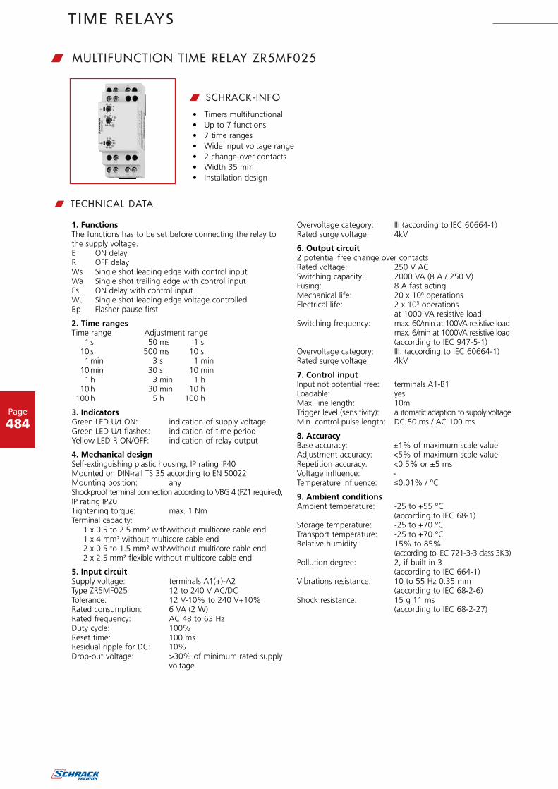
TIME RELAYS
Page
484
1. FunctionsThe functions has to be set before connecting the relay to the supply voltage.E ON delayR OFF delayWs Single shot leading edge with control inputWa Single shot trailing edge with control inputEs ON delay with control inputWu Single shot leading edge voltage controlledBp Flasher pause first
2. Time rangesTime range Adjustment range
1 s 50 ms 1 s10 s 500 ms 10 s
1 min 3 s 1 min 10 min 30 s 10 min
1 h 3 min 1 h10 h 30 min 10 h
100 h 5 h 100 h
3. IndicatorsGreen LED U/t ON: indication of supply voltageGreen LED U/t flashes: indication of time periodYellow LED R ON/OFF: indication of relay output
4. Mechanical designSelf-extinguishing plastic housing, IP rating IP40Mounted on DIN-rail TS 35 according to EN 50022Mounting position: anyShockproof terminal connection according to VBG 4 (PZ1 required),IP rating IP20Tightening torque: max. 1 NmTerminal capacity:
1 x 0.5 to 2.5 mm² with/without multicore cable end1 x 4 mm² without multicore cable end2 x 0.5 to 1.5 mm² with/without multicore cable end2 x 2.5 mm² flexible without multicore cable end
5. Input circuitSupply voltage: terminals A1(+)-A2Type ZR5MF025 12 to 240 V AC/DCTolerance: 12 V-10% to 240 V+10%Rated consumption: 6 VA (2 W)Rated frequency: AC 48 to 63 HzDuty cycle: 100%Reset time: 100 msResidual ripple for DC: 10%Drop-out voltage: >30% of minimum rated supply
voltage
Overvoltage category: III (according to IEC 60664-1)Rated surge voltage: 4kV
6. Output circuit2 potential free change over contactsRated voltage: 250 V ACSwitching capacity: 2000 VA (8 A / 250 V)Fusing: 8 A fast actingMechanical life: 20 x 106 operationsElectrical life: 2 x 10⁵ operations
at 1000 VA resistive loadSwitching frequency: max. 60/min at 100VA resistive load
max. 6/min at 1000VA resistive load(according to IEC 947-5-1)
Overvoltage category: III. (according to IEC 60664-1)Rated surge voltage: 4kV
7. Control inputInput not potential free: terminals A1-B1Loadable: yesMax. line length: 10mTrigger level (sensitivity): automatic adaption to supply voltageMin. control pulse length: DC 50 ms / AC 100 ms
8. AccuracyBase accuracy: ±1% of maximum scale valueAdjustment accuracy: <5% of maximum scale valueRepetition accuracy: <0.5% or ±5 msVoltage influence: -Temperature influence: �0.01% / °C
9. Ambient conditionsAmbient temperature: -25 to +55 °C
(according to IEC 68-1)Storage temperature: -25 to +70 °CTransport temperature: -25 to +70 °CRelative humidity: 15% to 85%
(according to IEC 721-3-3 class 3K3)Pollution degree: 2, if built in 3
(according to IEC 664-1)Vibrations resistance: 10 to 55 Hz 0.35 mm
(according to IEC 68-2-6)Shock resistance: 15 g 11 ms
(according to IEC 68-2-27)
• Timers multifunctional• Up to 7 functions• 7 time ranges• Wide input voltage range• 2 change-over contacts• Width 35 mm• Installation design
w TECHNICAL DATA
w SCHRACK-INFO
w MULTIFUNCTION TIME RELAY ZR5MF025

TIME RELAYS
Page
485
Order no. blue: on stock, usually ready for delivery on the day of order!
ON delay (E)When the supply voltage U is applied, the set interval t begins (greenLED U/t flashes). After the interval t has expired (green LED U/tilluminated) the output relay R switches into on-position (yellow LEDilluminated). This status remains until the supply voltage is interrupted.If the supply voltage is interrupted before the expiry of the interval t,the interval already expired is erased and is restarted when the supplyvoltage is next applied.
OFF delay (R)The supply voltage U must be constantly applied to the device (greenLED U/t illuminated). When the control contact S is closed, the outputrelay R switches into on-position (yellow LED illuminated). If the controlcontact is opened, the set interval t begins (green LED U/t flashes).After the interval t has expired (green LED U/t illuminated) the outputrelay switches into off-position (yellow LED not illuminated). If the controlcontact is closed again before the interval t has expired, the intervalalready expired is erased and is restarted.
Single shot leading edge with control input (Ws)The supply voltage U must be constantly applied to the device (greenLED U/t illuminated). When the control contact S is closed, the outputrelay R switches into on-position (green LED U/t illuminated) and theset interval t begins (green LED U/t flashes). After the interval t hasexpired (green LED U/t illuminated) the output relay switches intooff-position (yellow LED not illuminated). During the interval, the controlcontact can be operated any number of times. A further cycle can onlybe started when the cycle run has been completed.
Single shot trailling edge with control input (Wa)The supply voltage U must be constantly applied to the device (greenLED U/t illuminated). Closing the control contact S has no influence onthe condition of the output R. When the control contact is opened, theoutput relay switches into on-position (yellow LED illuminated) and theset interval t begins (green LED U/t flashes). After the interval t has expired(green LED U/t illuminated), the ouput relay switches into off-position (yel-low LED not illuminated). During the interval, the control contact can beoperated any number of times. A further cycle can only be started whenthe cycle run has been completed.
ON delay with control input (Es)The supply voltage U must be constantly applied to the device (greenLED U/t illuminated). When teh control contact S is closed, the setinterval t begins (green LED U/t flashes). After the interval t has expired(green LED U/t illuminated) the output relay R switches into on-posi-tion (yellow LED illuminated). This status remains until the controlcontact is opened again. If the control contact is opened before theinterval t has expired , the interval already expired is erased and isrestarted with the next cycle.
Single shot leading edge voltage controlled (Wu)When the supply voltage U is applied, the output relay R switchesinto on-position (yellow LED illuminated) and the set interval t begins(green LED U/t flashes). After the interval t has expired (green LED U/tilluminated) the output relay switches into off-position (yellow LED notilluminated). This status remains until the supply voltage is interrupted.If the supply voltage is interruted before the interval t has expired, theoutput relay switches into off-position. The interval already is erasedand is restarted when the supply voltage is next applied.
Flasher pause first (Bp)When the supply voltage U is applied, the set interval t begins (greenLED U/t flashes). After the interval t has expired, the output relay Rswitches into on-position (yellow LED illuminated) and the set interval tbegins again. After the interval t has expired, the output relay switchesinto off-position (yellow LED not illuminated).The output relay is triggered at a ratio of 1:1 until the supply voltage isinterrupted.
Single packing: 106g
with control input without control input
w FUNCTIONS
w DIMENSIONS
w WEIGHT
W ARTICLE NUMBER
DESCRIPTION ORDER NO.
Timerelay, multifunction, 12-240VAC, 2 change over, 8A/250V ZR5MF025
w CONNECTIONS
DESCRIPTION EAN CODE AVAILABLE ORDER NO.
Multifunction time relay, 12-240VAC, 2 change over, 8A/250V 9004840507287 ZR5MF025
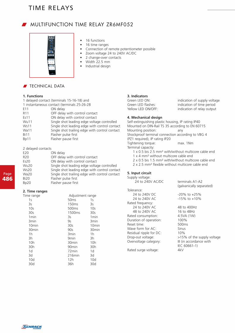
TIME RELAYS
Page
486
1. Functions1 delayed contact (terminals 15-16-18) and1 instantaneous contact (terminals 25-26-28E11 ON delayR11 OFF delay with control contactEs11 ON delay with control contactWu11 Single shot leading edge voltage controlledWs11 Single shot leading edge with control contactWa11 Single shot trailing edge with control contactBi11 Flasher pulse firstBp11 Flasher pause first
2 delayed contactsE20 ON delayR20 OFF delay with control contactEs20 ON delay with control contactWu20 Single shot leading edge voltage controlledWs20 Single shot leading edge with control contactWa20 Single shot trailing edge with control contactBi20 Flasher pulse firstBp20 Flasher pause first
2. Time rangesTime range Adjustment range
1s 50ms 1s3s 150ms 3s10s 500ms 10s30s 1500ms 30s1min 3s 1min3min 9s 3min10min 30s 10min30min 90s 30min1h 3min 1h3h 9min 3h10h 30min 10h30h 90min 30h1d 72min 1d3d 216min 3d10d 12h 10d30d 36h 30d
3. IndicatorsGreen LED ON: indication of supply voltageGreen LED flashes: indication of time periodYellow LED ON/OFF: indication of relay output
4. Mechanical designSelf-extinguishing plastic housing, IP rating IP40Mounted on DIN-Rail TS 35 according to EN 60715Mounting position: anyShockproof terminal connection according to VBG 4 (PZ1 required), IP rating IP20Tightening torque: max. 1NmTerminal capacity:
1 x 0.5 bis 2.5 mm² with/without multicore cable end1 x 4 mm² without multicore cable end2 x 0.5 bis 1.5 mm² with/without multicore cable end2 x 2.5 mm² flexible without multicore cable end
5. Input circuitSupply voltage:
24 to 240V AC/DC terminals A1-A2(galvanically separated)
Tolerance:24 to 240V DC -20% to +25%24 to 240V AC -15% to +10%
Rated frequency:24 to 240V AC 48 to 400Hz48 to 240V AC 16 to 48Hz
Rated consumption: 4.5VA (1W)Duration of operation: 100%Reset time: 500msWave form for AC: SinusResidual ripple for DC: 10%Drop-out voltage: >15% of the supply voltageOvervoltage category: III (in accordance with
IEC 60661-1)Rated surge voltage: 4kV
w TECHNICAL DATA
• 16 functions• 16 time ranges• Connection of remote potentiometer possible• Zoom voltage 24 to 240V AC/DC• 2 change-over contacts• Width 22.5 mm• Industrial design
w MULTIFUNCTION TIME RELAY ZR6MF052

TIME RELAYS
Page
487
6. Output circuit2 potential free change-over contactsRated voltage: 250V ACSwitching capacity (distance <5mm):
750VA (3A / 250V AC)Switching capacity (distance >5mm):
1250VA (5A / 250V AC)Fusing: 5A fast actingMechanical life: 20 x 106 operationsElectrical Life: 2 x 10⁵ operations at
1000VA resistive loadSwitching frequency: max. 60/min at 100VA
resistive loadmax. 6/min at 1000VAresistive load(in accordance with IEC 60947-5-1)
Overvoltage category: III (in accordance with IEC 60664-1)Rated surge voltage: 4kV
7. Control contactActivation: bridge Y1-Y2Potential free: yes, basic isolation against
input and output circuitLoadable: noControl voltage: max. 5VShort circuit current: max. 1mALine length: max. 10mControl pulse length: min. 50ms
8. Remote potentiometer (not included)
The internal potentiometer is de-activated when a remotepotentio-meter is connected!Connections: 1M potentiometer
(type RONDO R2), terminals Z1-Y2Line type: twisted pairControl voltage: max. 5VShort circuit current: max. μALine length: max. 5m
9. AccuracyBase accuracy: ±1% (of maximum scale value)
using 1M remote potentiometerFrequency response: -Adjustment accuracy: 5% (of maximum scale value)
using 1M remote potentiometerRepetition accuracy: <0.5% or ±5msVoltage influence: -Temperature influence: 0.01% / °C
10. Ambient conditionsAmbient temperature: -25 to +55°C
(in accordance with IEC 60068-1)-25 to +40°C(in accordance with UL 508)
Storage temperature: -25 to +70°CTransport temperature: -25 to +70°CRelative humidity: 15% to 85% (in accordance with
IEC 60721-3-3 class 3K3)Pollution degree: 3 (in accordance with IEC 60664-1)Vibration resistance: 10 to 55Hz 0.35 mm
(in accordance with IEC 60068-2-6)Shock resistance: 15g 11ms (in accordance with
IEC 60068-2-27)
w FUNCTIONS
The internal potentiometer is de-activated when a remote-poten-tio-meter is connected !The function has to be set before con-necting the relay to the supply voltage.
ON delay (E11)When the supply voltage U is applied, the instantaneous contactswitches into on-position and the set interval t begins (green LEDflashes). After the interval t has expired (green LED illuminated) thedelayed contact switches into on-position (yellow LED illuminated).This status remains until the supply voltage is interrupted. If thesupply voltage is interrupted before the expiry of the interval t, theinterval already expired is erased and is restarted when the supplyvoltage is next applied.
OFF delay with control contact (R11)The supply voltage U must be constantly applied to the device(green LED illuminated). When the control contact Y1-Y2 isclosed, both contacts switch into on-position (yellow LED illumi-nated). If the control contact is opened, the instantaneous contactswitches into off-position and the set interval t begins (green LEDflashes). After the interval t has expired (green LED illuminated)the delayed contact switches into off-position (yellow LED notilluminated). If the control contact is closed again before theinterval t has expired, the interval already expired is erased and isrestarted with the next cycle.
U
LED U
R15-16-18
R25-26-28
t <t
U
LED U
R15-16-18
R25-26-28
t
Y1-Y2
<t

TIME RELAYS
Page
488
ON delay with control contact (Es11)The supply voltage U must be constantly applied to the device(green LED illuminated). When the control contact Y1-Y2 isclosed, the instantaneous contact switches into on-position andthe set interval t begins (green LED flashes). After the interval thas expired (green LED illuminated) the delayed contact switchesinto on-position (yellow LED illuminated). This status remains untilthe control contact is opened again .If the control contact isopened before the interval t has expired, the interval alreadyexpired is erased and is restarted with the next cycle.
Single shot leading edge voltage controlled (Wu11)When the supply voltage U is applied, both contacts switch intoon-position (yellow LED illuminated) and the set interval t begins(green LED flashes). After the interval t has expired (green LEDilluminated) the delayed contact switches into off-position (yellowLED not illuminated). This status remains until the supply voltageis interrupted. If the supply voltage is interrupted before the inter-val t has expired, the both contacts switch into off-position. Theinterval already expired is erased and is restarted when the supplyvoltage is next applied.
Single shot leading edge with control contact (Ws11)The supply voltage U must be constantly applied to the device(green LED illuminated). When the control contact Y1-Y2 isclosed, both contacts switch into on-position (yellow LED illumi-nated) and the set interval t begins (green LED flashes). After theinterval t has expired (green LED illuminated) the delayed contactswitches into off-position (yellow LED not illuminated). Theinstantaneous contact remains in on-position, until the controlcontact is opened again. During the interval, the control contact(and the instantaneous contact) can be operated any number oftimes.A further cycle can only be started when the cycle run hasbeen completed.
Single shot trailing edge with control contact (Wa11)The supply voltage U must be constantly applied to the device(green LED illuminated). When the control contact Y1-Y2 is closedthe instantaneous contact switches into on-position. When thecontrol contact is opened, the instantaneous contact switchesinto off-position, the delayed contact switches into on-position(yellow LED illuminated) and the set interval t begins (green LEDflashes). After the interval t has expired (green LED illuminated),the delayed contact switches into off-position (yellow LED not illu-minated). During the interval, the control contact (and the instan-taneous contact) can be operated any number of times. A furthercycle can only be started when the cycle run has been completed.
Flasher pulse first (Bi11)When the supply voltage U is applied, the instantaneous contactand the delayed contact switch into on-position (yellow LED illu-minated) and the set interval t begins (green LED flashes). Afterthe interval t has expired, the delayed contact switches into off-position (yellow LED not illuminated) and the set interval t beginsagain. The delayed contact is triggered at a ratio of 1:1 until thesupply voltage is interrupted.
Flasher pause first (Bp11)When the supply voltage U is applied, the instantaneous contactswitches into on-position and the set interval t begins (green LEDflashes). After the interval t has expired, the delayed contactswitches into on-position (yellow LED illuminated) and the setinterval t begins again. After the interval t has expired, thedelayed contact switches into off-position (yellow LED not illumi-nated). The delayed contact is triggered at a ratio of 1:1 until thesupply voltage is interrupted.
U
LED U
R15-16-18
R25-26-28
t
Y1-Y2
<t
U
LED U
R15-16-18
R25-26-28
t <t
U
LED U
R15-16-18
R25-26-28
t t
Y1-Y2
U
LED U
R15-16-18
R25-26-28
t t
Y1-Y2
U
LED U
R15-16-18
R25-26-28
t t t t t
U
LED U
R15-16-18
R25-26-28
t t t t

TIME RELAYS
Page
489
ON delay (E20)When the supply voltage U is applied, the set interval t begins(green LED flashes). After the interval t has expired (green LEDilluminated) the output relay R switches into on-position (yellowLED illuminated). This status remains until the supply voltage isinterrupted.If the supply voltage is interrupted before the expiryof the interval t, the interval already expired is erased and isrestarted when the supply voltage is next applied.
OFF delay with control contact (R20)The supply voltage U must be constantly applied to the device(green LED illuminated). When the control contact Y1-Y2 isclosed, the output relay R switches into on-position (yellow LEDilluminated). If the control contact is opened, the set interval tbegins (green LED flashes). After the interval t has expired (greenLED illuminated) the output relay switches into off-position (yel-low LED not illuminated). If the control contact is closed againbefore the interval t has expired, the interval already expired iserased and is restarted with the next cycle.
ON delay with control contact (Es20)The supply voltage U must be constantly applied to the device(green LED illuminated). When the control contact Y1-Y2 isclosed, the set interval t begins (green LED flashes). After theinterval t has expired (green LED illuminated) the output relay Rswitches into on-position (yellow LED illuminated). This statusremains until the control contact is opened again. If the controlcontact is opened before the interval t has expired, the intervalalready expired is erased and is restarted with the next cycle.
Single shot leading edge voltage controlled (Wu20)When the supply voltage U is applied, the output relay R switch-es into on-position (yellow LED illuminated) and the set interval tbegins (green LED flashes). After the interval t has expired (greenLED illuminated) the output relay switches into off-position (yel-low LED not illuminated). This status remains until the supply volt-age is interrupted. If the supply voltage is interrupted before theinterval t has expired, the output relay switches into off-position.The interval already expired is erased and is restarted when thesupply voltage is next applied.
Single shot leading edge with control contact (Ws20)The supply voltage U must be constantly applied to the device(green LED illuminated). When the control contact Y1-Y2 isclosed, the output relay R switches into on-position (yellow LEDilluminated) and the set interval t begins (green LED flashes). Afterthe interval t has expired (green LED illuminated) the output relayswitches into off-position (yellow LED not illuminated). During theinterval, the control contact can be operated any number oftimes. A further cycle can only be started when the cycle run hasbeen completed.
Single shot trailing edge with control contact (Wa20)The supply voltage U must be constantly applied to the device(green LED illuminated). Closing the control contact Y1-Y2 has noinfluence on the condition of the output relay R. When the con-trol contact is opened, the output relay switches into on-position(yellow LED illuminated) and the set interval t begins (green LEDflashes). After the interval t has expired (green LED illuminated),the output relay switches into off-position (yellow LED not illumi-nated). During the interval, the control contact can be operatedany number of times. A further cycle can only be started when thecycle run has been completed.
U
LED U
R15-16-18
R25-26-28
t <t
U
LED U
R15-16-18
R25-26-28
t <t
Y1-Y2
U
LED U
R15-16-18
R25-26-28
t
Y1-Y2
<t
U
LED U
R15-16-18
R25-26-28
t <t
U
LED U
R15-16-18
R25-26-28
t t
Y1-Y2
U
LED U
R15-16-18
R25-26-28
t t
Y1-Y2

TIME RELAYS
Page
490
Order no. blue: on stock, usually ready for delivery on the day of order!
Flasher pulse first (Bi20)When the supply voltage U is applied, the output relay R switch-es into on-position (yellow LED illuminated) and the set interval tbegins (green LED flashes). After the interval t has expired, theoutput relay switches into off-position (yellow LED not illuminat-ed) and the set interval t begins again. The output relay istriggered at a ratio of 1:1 until the supply voltage is interrupted.
Flasher pause first (Bp20)When the supply voltage U is applied, the set interval t begins(green LED flashes). After the interval t has expired, the outputrelay R switches into on-position (yellow LED illuminated) and theset interval t begins again. After the interval t has expired, theoutput relay switches into off-position (yellow LED not illuminat-ed). The output relay is triggered at a ratio of 1:1 until the supplyvoltage is interrupted.
U
LED U
R15-16-18
R25-26-28
t t t t t
U
LED U
R15-16-18
R25-26-28
t t t t t
15
16 18
25
26 28
A1
A2
Y1
Y2Z1
15
16 18
25 26 28
R2
1
2
3
S
w CONNECTIONS w DIMENSIONS
DESCRIPTION EAN CODE AVAILABLE ORDER NO.
Multifunction time relay, 2 change over, 24-240V AC/DC, industrial design 9004840557466 ZR6MF052
I KNOW WHERE TO FIND IT!
WITH THE SCHRACK TECHNIK LiVE-PHONE APP
• Access technical product information at any time and from everywhere
• See availability and price immediately
• Order desired products easily

TIME RELAYS
Page
491
1. FunctionsIp Asymmetric flasher pause firstIi Asymmetric flasher pulse first
(A1-B1 bridged)
2. Time rangesTime range Adjustment range 1 s 50 ms 1 s
10 s 500 ms 10 s 1 min 3 s 1 min 10 min 30 s 10 min 1 h 3 min 1 h
10 h 30 min 10 h100 h 5 h 100 h
3. IndicatorsGreen LED U/t ON: indication of supply voltageGreen LED U/t slow flashing: indication of time period t1Green LED U/t fast flashing: indication of time period t2Yellow LED R ON/OFF: indication of relay output
4. Mechanical designSelf-extinguishing plastic housing, IP rating IP40Mounted on DIN-rail TS 35 according to EN 50022Mounting position: anyShockproof terminal connection according to VBG 4 (PZ1 required),IP rating IP20Tightening torque: max. 1 NmTerminal capacity:
1 x 0.5 to 2.5 mm² with/without multicore cable end1 x 4 mm² without multicore cable end2 x 0.5 to 1.5 mm² with/without multicore cable end2 x 2.5mm ² flexible without multicore cable end
5. Input circuitSupply voltage: Terminals A1(+)-A2Type ZR5B001112-240 V AC/DC: 12 to 240 V AC/DC
Tolerance: 12 V-10% to 240 V+10%Rated consumption: 4 VA (1.5 W)Rated frequency: AC 48 to 63 HzDuty cycle: 100%Reset time: 100 msResidual ripple for DC: 10%Drop-out voltage: >30% of minimum rated supply
voltageOvervoltage category: III (according to IEC 60664-1)
Rated surge voltage: 4 kV
6. Output circuit1 potential free change over contactRated voltage: 250 V ACSwitching capacity: 2000 VA (8 A / 250 V)Fusing: 8 A fast actingMechanical life: 20 x 106 operationsElectrical life: 2 x 10⁵ operations
at 1000 VA resistive loadSwitching frequency: max. 60/min at 100 VA resistive
loadmax. 6/min at 1000 VA resistiveload(according to IEC 947-5-1)
Overvoltage category: III. (according to IEC 60664-1)Rated surge voltage: 4 kV
7. Control inputInput not potential free: Terminals A1-B1Loadable: yesMax. line length: 10 mTrigger level (sensitivity): automatic adaption to supply
voltageMin. control pulse length: DC 50 ms / AC 100 ms
8. AccuracyBase accuracy: ±1% of maximum scale valueAdjustment accuracy: <5% of maximum scale valueRepetition accuracy: <0.5% or ±5 msVoltage influence: -Temperature influence: �0.01% / °C
9. Ambient conditionsAmbient temperature: -25 to +55 °C (according to IEC 68-1)Storage temperature: -25 to +70 °CTransport temperature: -25 to +70 °CRelative humidity: 15% to 85%
(according to IEC 721-3-3 class 3K3)Pollution degree: 2, if built in 3
(according to IEC 664-1)Vibration resistance: 10 to 55 Hz 0.35 mm
(according to IEC 68-2-6)Shock resistance: 15 g 11 ms
(according to IEC 68-2-27)
• Asymmetric flasher• 7 time ranges• Wide input voltage range• 1 change over contact• Width 17,5 mm• Installation design
w TECHNICAL DATA
w SCHRACK-INFO
w FLASHER TIME RELAY ZR5B0011

TIME RELAYS
Page
492
Asymmetric flasher pause first (Ip)When the supply voltage U is applied, the set interval t1 begins (green LED U/t flashes slowly). After the interval t1 has expired, the output relay R switches into on-position (yellow LED illuminated) and the set interval t2 begins (green LED U/t flashes fast). After the interval t2 has expired, the output relay switches into off-position (yellow LED not illuminated).
The output relay is triggered at the ratio of t1:t2 until the supply voltage is interrupted.
Asymmetric flasher pulse first (Ii)When the supply voltage U is applied, the output relay R switches into on-position (yellow LED illuminated) and the set interval t1 begins (green LED U/t flashes slowly). After theinterval t1 has expired, the output relay switches into off-position (yellow LED not illuminated) and the set interval t2 begins (green LED U/t flashes fast). After the interval t2 has expired, the output relay switches into on-position (yellow LED illuminated).
The output relay is triggered at the ratio of t1:t2 until the supply voltage is interrupted
Single packing: 72 gPackage 10 pcs: 670 g per Package
w FUNCTIONS w CONNECTIONS
w DIMENSIONS
w WEIGHT W ARTICLE NUMBER
DESCRIPTION ORDER NO.
Timerelay, 12-240VAC, 1 change over, 8A/250V ZR5B0011
DESCRIPTION EAN CODE AVAILABLE ORDER NO.
Flasher time relay, 12-240VAC, 1 change over, 8A/250V 9004840459012 ZR5B0011
Order no. blue: on stock, usually ready for delivery on the day of order!
I KNOW WHERE TO FIND IT!
THE SCHRACK TECHNIK WEB SHOP WITH NAVIGATORWWW.SCHRACK.COM
• Finding product information made easy
• Buying products around the clock
• Quick access customer service

TIME RELAYS
Page
493
1. FunctionsThe function has to be set before connecting the relay to the supply voltage.Ip Asymmetric flasher pause firstIi Asymmetric flasher pulse firstER ON delay and OFF delay with control contactEWu ON delay single shot leading edge voltage controlledEWs ON delay single shot leading edge with control
contactWsWa Single shot leading and single shot trailling edge
with control contactWt Pulse sequence monitoring
2. Time rangesTime range Adjustment range
1 s 50 ms 1 s10 s 500 ms 10 s
1 min 3 s 1 min 10 min 30 s 10 min
1 h 3 min 1 h10 h 30 min 10 h
100 h 5 h 100 h
3. IndicatorsGreen LED U/t ON: indication of supply voltageGreen LED U/t slow flashing: indication of time period t1Green LED U/t fast flashing: indication of time period t2Yellow LED ON/OFF: indication of relay output
4. Mechanical designSelf-extinguishing plastic housing, IP rating IP40Mouted on DIN-rail TS 35 according to EN 50022Mounting position: anyShockproof terminal connection according to VBG 4 (PZ1 required),IP rating IP20Tightening torque: max. 1 NmTerminal capacity:
1 x 0.5 to 2.5 mm² with/without multicore cable end1 x 4 mm² without multicore cable end2 x 0.5 to 1.5 mm² with/without multicore cable end2 x 2.5 mm² flexible without multicore cable end
5. Input circuitSupply voltage: terminals A1(+) - A2Types ZR5B002512-240 V AC/DC: 12 to 240 V AC/DCTolerance: 12 V-10% to 240 V+10%Rated frequency: 48 to 63 HzRated consumption: 6 VA (2 W)Duration of operation: 100%
Reset time: 100 msResidual ripple of DC: -Drop-out voltage: >30% of the supply voltageOvervoltage category: III (according to IEC 60664-1)Rated surge voltage: 4kV
6. Output circuit2 potential free change over contactsRated voltage: 250 V ACSwitching capacity: 2000 VA (8 A / 250 V)Fusing: 8 A fast actingMechanical life: 20 x 106 operationsElectrical life: 2 x 10⁵ operations
at 1000 VA resistive loadSwitching frequency: max. 60/min at 100 VA resistive load
max. 6/min at 1000 VA resistive load(according to IEC 947-5-1)
Overvoltage category: III (according to IEC 60664-1)Rated surge: 4 kV
7. Control inputInput not potential free: terminals A1-B1Loadable: yesMax. line length: 10 mTrigger level (sensitivity): automatic adaption to supply voltageMax. control pulse length: DC 50 ms / AC 100 ms
8. AccuracyBase accuracy: ±1% of maximum scale valueAdjusting accuracy: �5% of maximum scale valueRepetition accuracy: <0.5% or ±5 msVoltage influence: -Temperature influence: �0.01% / °C
9. Ambient conditionsAmbient temperature: -25 to +55 °C (according to IEC 68-1)Storage temperature: -25 to +70 °CTransport temperature: -25 to +70 °CRelative humidity: 15% to 85%
(according to IEC 721-3-3 class 3K3)Pollution degree: 2, if built in 3
(according to IEC 664-1)Vibration resistance: 10 to 55 Hz 0.35 mm
(according to IEC 68-2-6)Shock resistance: 15 g 11 ms
(according to IEC 68-2-27)
• Asymmetric flasher, 2-time multifu• 7 Time ranges• Wide input voltage range• 2 change-over contacts• Width 35 mm• Installation design
w TECHNICAL DATA
w SCHRACK-INFO
w PULSE TIME RELAY ZR5B0025

TIME RELAYS
Order no. blue: on stock, usually ready for delivery on the day of order!
Page
494
Asymmetric flasher pause first (lp)When the supply voltage U is applied, the set interval t1 begins (greenLED U/t flashes slowly). After the interval t1 has expired, the outputrelay R switches into on-position (yellow LED illuminated) and the setinterval t2 begins (green LED U/t flashes fast). After the interval t2 hasexpired, the output relay switches into off-position (yellow LED notilluminated). The output relay is triggered at the ratio of t1:t2 until thesupply voltage is interrupted.
Asymmetric flasher pulse first (li)When the supply voltage U is applied, the output relay R switches intoon-position (yellow LED illuminated) and the set interval t1 begins (greenLED U/t flashes slowly). After the interval t1 has expired, the output relayswitches into off-position (yellow LED not illuminated) and the set intervalt2 begins (green LED U/t flashes fast). After the interval t2 has expired,the output relay switches into on-position (yellow LED illuminated). Theoutput relay is triggered at the ratio of t1:t2 until the supply voltage isinterrupted.
ON delay and OFF delay with control contact (ER)The supply voltage U must be constantly applied to the device (green LEDU/t illuminated). When the control contact S is closed, the set interval t1begins (green LED U/t flashes slowly). After the interval t1 has expired, theoutput relay R switches into on-position (yellow LED illuminated). If thecontrol contact is opened, the set interval t2 begins (green LED U/t flashesfast). After the interval t2 has expired, the output relay switches intooff-position (yellow LED not illuminated). If the control contact is openedbefore the interval t1 has expired, the interval already expired is erasedand is restarted with the next cycle.
ON delay and single shot leading edge voltagecontrolled (EWu)When the supply voltage U is applied, the set interval t1 begins (green LEDU/t flashes slowly). After the interval t1 has expired, the output relay Rswitches into on-position (yellow LED illuminated) and the set interval t2begins (green LED U/t flashes fast). After the interval t2 has expired, theoutput relay switches into off-position (yellow LED not illuminated). If thesupply voltage is interrupted before the interval t1+t2 has expired, theinterval already expired is erased and is restarted when the supply voltageis next applied.
ON delay and single shot leading edgewith control contact (EWs)The supply voltage U must be constantly applied to the device(green LED U/t illuminated). When the control contact S is closed,the set interval t1 begins (green LED U/t flashes slowly). After theinterval t1 has expired, the output relay R switches into on-position(yellow LED illuminated) and the set interval t2 begins (green LEDU/t flashes fast). After the interval t2 has expired, the output relayswitches into off-position (yellow LED not illuminated).During the interval, the control contact can be operated any number
Single shot leading and single shot trailing edgewith control contact (WsWa)The supply voltage U must be constantly applied to the device (green LEDU/t illuminated). When the control contact S is closed, the output relayR switches into on-position (yellow LED illuminated) and the set intervalt1 begins (green LED U/t flashes slowly). After the interval t1 has expired,the output relay R switches into off-position (yellow LED not illuminated).If the control contact is opened, the output relay again switches into on-position (yellow LED illuminated) and the set interval t2 begins (greenLED U/t flashes fast). After the interval t2 has expired the output relayswitches into off-position (yellow LED not illuminated). During the inter-val, the control contact can be operated any number of times.
Pulse sequence monitoring (Wt)When the supply voltage U is applied, the set interval t1 begins (greenLED U/t flashes slowly) and the output relay R switches into on-position(yellow LED illuminated) After the interval t1 has expired, the set intervalt2 begins (green LED U/t flashes fast). So that the output relay R remainsin on-position, the control contact S must be closed and opened againwithin the set interval t2. If this does not happen, the output relay Rswitches into off-position (yellow LED not illuminated) and all furtherpulses at the control contact are ignored. To restart the function thesupply voltage must be interrupted and reapplied.
Single packing: 106g
of times. A further cycle can only be started when the cycle run hasbeen completed.
w FUNCTIONS
w CONNECTIONS w DIMENSIONS
w WEIGHT
W ARTICLE NUMBER
DESCRIPTION ORDER NO.
Timerelay, 7 functions, 12-240VAC, 2 change over, 8A/250V ZR5B0025
DESCRIPTION EAN CODE AVAILABLE ORDER NO.
Pulse time relay, 7 functions, 12-240VAC, 2 change over, 8A/250V 9004840507263 ZR5B0025

TIME RELAYS
Page
495
1. FunctionsS Star-delta start up
2. Time rangesStart-up timeTime range Adjustment range
10 s 500 ms 10 s30 s 1500 ms 30 s
1 min 3 s 1 min 3 min 9 s 3 min
Transit time (fixed) 40 ms 60 ms 80 ms 100 ms
3. IndicatorsGreen LED U/t ON: indication of supply voltage
delta-contactor in on-position(terminals 25-28)
Green LED U/t flashes: indication of time period star timeYellow LED R ON/OFF: indication of star contactor
(terminals 15-18)
4. Mechanical designSelf-extinguishing plastic housing, IP rating IP40Mounted on DIN-rail TS 35 according to EN 50022Mounting position: anyShockproof terminal connection according to VBG 4 (PZ1 required),IP rating IP20Tightening torque: max. 1 NmTerminal capacity:
1 x 0.5 to 2.5 mm² with/without multicore cable end1 x 4 mm² without multicore cable end2 x 0.5 to 1.5 mm² with/without multicore cable end2 x 2.5 mm² flexible without multicore cable end
5. Input circuitSupply voltage: terminals A1(+)-A2Type ZR5SD025 12 to 240 V AC/DCTolerance: 12 V-10% to 240 V+10%Rated consumption: 4 VA (1.5 W)Rated frequency: AC 48 to 63HzDuty cycle: 100%
Reset time: 100 msResidual ripple of DC: 10%Drop-out voltage: >30% of the supply voltageOvervoltage category: III (according to IEC 60664-1)Rated surge voltage: 4 kV
6. Output circuit2 potential free change over contactsRated surge: 250 V ACSwitching capacity: 2000 VA (8 A / 250 V)Fusing: 8 A fast actingMechanical life: 20 x 106 operationsElectrical life: 2 x 10⁵ operations
at 1000 VA resistive loadSwitching frequency: max. 60/min at 100 VA
resistive loadmax. 6/min at 1000 VAresistive load(according to IEC 947-5-1)
Overvoltage category: III. (according to IEC 60664-1)Rated surge voltage: 4 kV
7. AccuracyBase accuracy: ±1% of maximum scale valueAdjustment accuracy: <5% of maximum scale valueRepetition accuracy: <0.5% or ±5 msVoltage influence: -Temperature influence: �0.01% / °C
8. Ambient conditionsAmbient temperature: -25 to +55 °C
(according to IEC 68-1)Storage temperature: -25 to +70 °CTransport temperature: -25 to +70 °CRelative humidity: 15% to 85%
(according to IEC 721-3-3Klasse 3K3)
Pollution degree: 2, if built in 3(according to IEC 664-1)
Vibration resistance: 10 to 55 Hz 0.35 mm(according to IEC 68-2-6)
Shock resistance: 15 g 11 ms(according to IEC 68-2-27)
• Star-Delta start up• 2 change-over contacts• Wide input voltage ran• Width 35 mm• Installation design
w TECHNICAL DATA
w SCHRACK-INFO
w STAR-DELTA-RELAY ZR5SD025

TIME RELAYS
w GEWICHT
w FUNCTIONS
Star-delta start upWhen the supply voltage U is applied, the star-contactswitches into on-position (yellow LED illuminated) and theset star-time t1 begins (green LED U/t flashes). After theinterval t1 has expired (green LED U/t illuminated), thestar-contact switches into off-position (yellow LED notilluminated) and the set transit-time t2 begins. After the interval t2 has expired, the contact for the delta-contactor switches into on-position. To restart the function, the supply voltage must be interrupted and reapplied.
Single packing: 106 g
w CONNECTIONS
w DIMENSIONS
W ARTICLE NUMBER
DESCRIPTION ORDER NO.
Star-Delta-relay, 12-240VAC, 2 change over ZR5SD025
DESCRIPTION EAN CODE AVAILABLE ORDER NO.
Star-delta-relay, 12-240VAC, 2 change over 9004840507300 ZR5SD025
Page
496
Order no. blue: on stock, usually ready for delivery on the day of order!
I KNOW WHERE TO FIND IT!
WITH THE SCHRACK TECHNIK LiVE-PHONE APP
• Access technical product information at any time and from everywhere
• See availability and price immediately
• Order desired products easily
w WEIGHT

TIME RELAYS
1. FunctionsS Star-Delta start-up
2. ZeitbereicheStart-up timeTime range Adjustment range
10s 500ms 1s3s 1500ms 30s1min 3s 1min3min 9s 3min
Transit timeTime range (fixed)
40ms60ms80ms100ms
3. IndicatorsGreen LED ON: indication of supply voltage
delta-contactor in on-position(terminals 25-28)
Green LED flashes: indication of star-timeYellow LED ON/OFF: indication of star-contactor
(terminals 15-18)
4. Mechanical designSelf-extinguishing plastic housing, IP rating IP40Mounted on DIN-Rail TS 35 according to EN 50022Mounting position: anyShockproof terminal connection according to VBG 4(PZ1 required), IP rating IP20Tightening torque: max. 1NmTerminal capacity:
1 x 0.5 bis 2.5 mm² with/without multicore cable end1 x 4 mm² without multicore cable end2 x 0.5 bis 1.5 mm² with/without multicore cable end2 x 2.5 mm² flexible without multicore cable end
5. Input circuitSupply voltage:
12 to 400V AC terminals A1-A2 (galvanicallyseparated) selectable via powermodules TR2
Tolerance: according to specification ofpower module
Rated frequency: according to specification ofpower module
Rated consumption: 2VA (1.5W)Duration of operation: 100%Reset time: 100msResidual ripple for DC: -Drop-out voltage: >30% of the supply voltageOvervoltage category: III (in accordance with
IEC 60664-1)Rated surge voltage: 4kV
6. Output circuit2 potential free change-over contactsRated voltage: 250V ACSchaltleistung: 750VA (3A / 250V AC)If the distance between the devices is less than 5mm!Switching capacity: 1250VA (5A / 250V AC)If the distance between the devices is greater than 5mm!Fusing: 5A fast actingMechanical life: 20 x 106 operationsElectrical Life: 2 x 10⁵ operations at 1000VA
resistive loadSwitching frequency: max. 60/min bei 100VA
resistive loadmax. 6/min bei 1000VAresistive load (in accordance withIEC 60947-5-1)
Overvoltage category: III (in accordance with IEC 60664-1)Rated surge voltage: 4kV
7. AccuracyBase accuracy: ±1% (of maximum scale value)Frequency response: -Adjustment accuracy: 5% (of maximum scale value)Repetition accuracy: <0.5% or ±5msVoltage influence: -emperature influence: 0.01% / °C
w TECHNICAL DATA
• Star-Delta start-up• Supply voltage selectable via power modules• 2 change-over contacts• Width 22.5 mm• Industrial design
w STAR-DELTA-RELAY ZR6SD052
Page
497

TIME RELAYS
Page
498
8. Ambient conditionsAmbient temperature: -25 to +55°C
(in accordance with IEC 60068-1)-25 to +40°C(in accordance with UL 508)
Storage temperature: -25 to +70°CTransport temperature: -25 to +70°CRelative humidity: 15% to 85% (in accordance with
IEC 60721-3-3 class 3K3)Pollution degree: 3 (in accordance with IEC 60664-1)Vibration resistance: 10 to 55Hz 0.35mm
(in accordance with IEC 60068-2-6)Shock resistance: 15g 11ms (in accordance with
IEC 60068-2-27)
w FUNCTIONS
Star-Delta start-up (S)When the supply voltage U is applied, the star-contact switchesinto on-position (yellow LED illuminated) and the set star-time t1begins (green LED flashing). After the interval t1 has expired(green LED il-luminated) the star-contact switches into off-posi-tion (yellow LED not illuminated) and the set transit-time t2begins. After the interval t2 has expired the delta-contact switch-es into on-position. To restart the function the supply voltagemust be interrupted and re-applied.
U
LED U
R15-16-18
R25-26-28
t1 t2
15
16 18
25
26 28
A1
A2
15
16 18
25 26 28
w CONNECTIONS w CONNECTIONS
DESCRIPTION EAN CODE AVAILABLE ORDER NO.
Star-delta-relay, 2 change over, industrial design 9004840557459 ZR6SD052
Order no. blue: on stock, usually ready for delivery on the day of order!
I KNOW WHERE TO FIND IT!
THE SCHRACK TECHNIK WEB SHOP WITH NAVIGATORWWW.SCHRACK.COM
• Finding product information made easy
• Buying products around the clock
• Quick access customer service
w DIMENSIONS

TIME RELAYS
1. FunctionsWs Single shot leading edge
with control contact
2. Time rangesTime range reversible between
10min, 30min, 60min, 90min, 2h and 3h
3. IndicatorsGreen LED U/t ON: indication of supply voltageGreen LED U/t flashes: indication of time period tGreen LED U/t flashes fast: abort of time period tYellow LED ON/OFF: indication of relay output
4. Mechanical designSelf-extinguishing plastic housing, IP rating IP 40Mounted on DIN-rail TS 35 according to EN 60715Mounting position: anyShockproof terminal connection according to VBG 4 (PZ1 required), IP rating IP20Tightening torque: max. 1NmTerminal capacity:
1 x 0.5 to 2.5 mm² with/without multicore cable end1 x 4 mm² without multicore cable end2 x 0.5 to 1.5 mm² with/without multicore cable end2 x 2.5 mm² flexible without multicore cable end
5. Input circuitSupply voltage: 230V ACTerminals: L-NTolerance: -15% to +10%Rated frequency: 48 to 63HzRated consumption: 2VA (1.0W)Duty cycle: 100%Reset time: 500msRipple and noise at DC: -Drop out voltage: >30% of supply voltageOvervoltage category: III (in accordance with IEC 60664-1)Rated surge voltage: 4kV
6. Output circuit1 change over contact
NORMALLY OPEN CONTACTTerminals: L-18Rated voltage: 250V ACSwitching capacity: 1250VA (5A / 250V AC)
NORMALLY CLOSED CONTACTTerminals: L-16Rated voltage: 250V ACSwitching capacity: 2500VA (10A / 250V AC)If the distance between the devices is less than 5mm!
Switching capacity: 4000VA (16A / 250V AC)If the distance between the devices is greater than 5mm!Start-up peak (20ms): 80A
Mechanical life: 30 x 106 operationsElectrical life:Resistive load: 105 operations at 16A 250VLamp load: 80.000 operations at 1000W 250V
7. AccuracyBase accuracy: ±5% Adjustment accuracy: -Repetition accuracy: <2% Voltage influence: -Temperature influence: 1%
8. Ambient conditionsAmbient temperature: -25 to +55°CStorage temperature: -25 to +70°CTransport temperature: -25 to +70°CRelative humidity: 15% to 85% (in accordance with
IEC 60721-3-3 class 3K3)Pollution degree: 2, if built in 3
(in accordance with IEC 60664-1)
w TECHNICAL DATA
• Timer for automatic test of emergency lights• Integrated test key• 1 change over contact• Width 17.5 mm• Installation design
w EMERGENCY LIGHT TEST RELAY ZR5RT011
Page
499

TIME RELAYS
Page
500
w FUNCTIONS
Single shot leading edge with control contact (Ws)The supply voltage U must be constantly to the device (green LEDU/t illuminated). Pressing the integrated test key forces the out-put relay R to switch into on-position (yellow LED illuminated), sothe emergency ligths are disconnected from the mains and theset interval t begins (green LED U/t flashes). After the interval thas expired (green LED U/t illuminated), the output relay R switches into off-position (yellow LED not illuminated) and theemergency lights are reconnected to the mains. During the interval, the test key can be operated any number of times.Prolonged pressure on the test key (>2s) aborts the running testinterval (green LED U/t flashes fast) and a further cycle can bestarted.
w CONNECTIONS
Ws LED U/t
RTestkey
U
t>2s
LN
PE
18 N
16
L
16 18
L
Emergency lights with integrated recharchable
power cells
LN
PE
18 N
16
L
16 18
L
Emergency lights with integrated recharchable
power cells
Direct connection of emergency lights (I < 16A) Switching emergency lights with contactor (I > 16A)
w DIMENSIONS
17,5mm44mm
60mm
87m
m
45m
m
5mm
DESCRIPTION EAN CODE AVAILABLE ORDER NO.
Emergency light test relay 9004840557374 ZR5RT011
Order no. blue: on stock, usually ready for delivery on the day of order!

LOAD SHEEDING RELAYS
Page
501
W SCHRACK INFO• For reduction of the necessary cross section of a line with big consumers
• Also for electronically regulated instantaneous water heater
• Assembly on DIN-rail according to DIN EN 50 052 or mounting plate
Rated current range AC 6,7…39 A
Rated power range for load at 230 V AC 1,5…9 kW
Rated power range for load at AC 3~230/400 V 4,6…27 kW
Operating power consumption 0,5…4 VA
Tripping current ≤ 5,7 A AC
Maximum continuous current 43 A AC
Thermal continuos load at 40°C 2,5 W
Connection (a and b) screw terminal; wire cross section 2,5…16 mm2
Contact 1 NC
Rated current at 250 V AC 1 A
Contact material silver plated
Maximum switching voltage 400 V AC
Maximum switching capacity 250 VA
Peak inrush current 5 A
Electrical life at rated load 105 operations
Mechanical life 10 x 106 operations
Duty cycle 100%
Max. switching frequency 1800 operations/hour at rated load
Max. operating temperature 40°C
Opening time/closing time 10…20 ms/≥ 20 ms
Contact resistance ca. 3 mΩTest voltage: contact/winding 2500 V AC
Insulation class acc. to VDE 0110 C/250 V
Protection degree housing IP 40
Connection (1 and 2) Schraubklemmen
Wire cross section (1 and 2) 0,75…4 mm2
Weight ca. 90 g
w TECHNICAL DATA
w LOAD SHEEDING RELAY BZ601000
DESCRIPTION EAN CODE AVAILABLE ORDER NO.
Load sheeding relay 6,7 – 39 A 400V-AC 9004840378429 BZ601000
Order no. blue: on stock, usually ready for delivery on the day of order!

MONITORING RELAYS
Page
502
1. FunctionsAC/DC undervoltage monitoring in 1-phase mains with adjustable threshold and xed hysteresis.
UNDER Undervoltage monitoring
2. Time rangesAdjustment range
Tripping delay (Delay): -
3. Indicators Green LED ON/OFF: indication of supply voltage
Yellow LED ON/OFF: indication of relay output
4. Mechanical designSelf-extinguishing plastic housing, IP rating IP40Mounted on DIN rail TS 35 according to EN 50022Mounting position: anyShockproof terminal connection according to VBG 4 (PZ1 required), IP rating IP20Tightening torque: max. 1NmTerminal capacity:
1 x 0.5 to 2.5mm² with/without multicore cable end1 x 4mm² without multicore cable end2 x 0.5 to 1.5mm² with/without multicore cable end2 x 2.5mm² flexible without multicore cable end
5. Input circuitSupply voltage: (= measuring voltage)Terminals: 230V AC E-F3 24V AC E-F2 (distance > 5mm) 24V DC E-F1(+)Rated voltage Un: see table ordering information or
printing on the unitTolerance: -25% to +20% of UnRated consumption: 230V AC 10VA (0.6W) 24V AC 1.3VA (0.8W) 24V DC 0.6WRated frequency: AC 48 to 63HzDuration of operation: 100%Reset time: 500msWave form: DC, AC SinusHold-up time: -Drop-out voltage: >60% of supply voltageOvervoltage category: III (according to IEC 60664-1)Rated surge voltage: 4kV
6. Output circuit1 potential free change over contactRated voltage: 250V ACSwitching capacity: 1250VA (5A / 250V)Fusing: 5A fast actingMechanical life: 20 x 106 operationsElectrical life: 2 x 10⁵ operations
at 1000VA resistive loadSwitching frequency: max. 60/min at 100VA resistive load
max. 6/min at 1000VA resistive load(according to IEC 947-5-1)
Overvoltage category: III. (according to IEC 60664-1)Rated surge voltage: 4kV
7. Measuring circuitMeasuring variable: DC or AC Sinus, 48 to 63HzMeasuring input: (= supply voltage)Terminals: 230V AC E-F3 24V AC E-F2 Distance between the devices
musst be greater than 5mm! 24V DC E-F1(+)Overload capacity: 120% of UnInput resistance: -Switching threshold Us: see table ordering information or
printing on the unitHysteresis H: see table ordering information or
printing on the unitOvervoltage category: III (according to IEC 60664-1)Rated surge voltage: 4kV
8. AccuracyBase accuracy: ±5% of rated valueAdjustment accuracy: ±5% of rated valueRepetition accuracy: 2% of rated valueVoltage influence: -Temperature influence: 0,05% / °C
9. Ambient conditionsAmbient temperature: -25 to +55°C (according to IEC 68-1)Storage temperature: -25 to +70°CTransport temperature: -25 to +70°CRelative humidity: 15% to 85%
(according to IEC 721-3-3 class 3K3)Pollution degree: 2, if built in 3
(according to IEC 664-1)Vibration resistance: 10 to 55 Hz 0.35mm
(according to IEC 68-2-6)Shock resistance: 15g 11ms
(according to IEC 68-2-27)
10. WeightSingle packing: 74gPackage of 10pcs: 676g per Package
AC/DC voltage monitoring in 1-phase mains
Undervoltage monitoring
1 change over contact
Width 17.5 mm
Installation design
w TECHNICAL DATA
w SCHRACK-INFO
w VOLTAGE MONITORING RELAY UR5U1011

Page
503
MONITORING RELAYS
w CONNECTIONS
w DIMENSIONS
w FUNCTIONS
The supply voltage U must be constantly applied to the device (green LED illuminated).The output relay R switches into on-position (yellow LED illuminated) when the measured voltage U exceeds the value adjusted at the Us-regulator. The output relay R switches into off-position (yellow LED not illuminated) when the measured value for the voltage falls below the set value by more than the fixed hysteresis.
Us
H
R
LED U
F3 F2
11
12 14
R
E F1
12 1411
L
N
1~230VAC
17,5mm60mm
87m
m
44mm5mm
45m
m
1~24VAC
F3 F2
11
12 14
R
E F1
12 1411
L
N24VDC
F3 F2
11
12 14
R
E F1
12 1411
+
-
DESCRIPTION EAN CODE AVAILABLE ORDER NO.
Voltage monitoring relay, 1 change over, 1 phase, AC/DC 9004840517125 UR5U1011
Order no. blue: on stock, usually ready for delivery on the day of order!

MONITORING RELAYS
Page
504
1. FunctionsAC/DC voltage monitoring in 1-phase mains with adjustablethresholds, timing for start-up suppression and tripping delayseparately adjustable and the following functions (selectable bymeans of rotary switch)OVER Overvoltage monitoringOVER+LATCH Overvoltage monitoring with
fault latchUNDER Undervoltage monitoringUNDER+LATCH Undervoltage monitoring with
fault latchWIN Monitoring the window
between Min and MaxWIN+LATCH Monitoring the window
between Min and Max withfault latch
2. Time rangesAdjustment range
Start-up suppression time: 0s 10sTripping delay: 0.1s 10s
3. IndicatorsGreen LED ON: indication of supply voltageGreen LED flashes: indication of start-up
suppression timeYellow LED ON/OFF: indication of relay outputRed LED ON/OFF: indication of failure of the
corresponding thresholdRed LED flashes: indication of tripping delay of
the corresponding threshold
4. Mechanical designSelf-extinguishing plastic housing, IP rating IP40Mounted on DIN-Rail TS 35 according to EN 60715Mounting position: anyShockproof terminal connection according to VBG 4(PZ1 required),IP rating IP20Tightening torque: max. 1NmTerminal capacity:
1 x 0.5 bis 2.5 mm² with/without multicore cable end1 x 4 mm² without multicore cable end2 x 0.5 bis 1.5 mm² with/without multicore cable end2 x 2.5 mm² flexible without multicore cable end
5. VersorgungskreisSupply voltage:
24 to 240V AC/DC terminals A1-A2 (galvanicallyseparated)
Tolerance:24 to 240V DC -20% to +25%24 to 240V AC -15% to +10%
Rated frequency:24 to 240V AC 48 to 400Hz48 to 240V AC 16 to 48Hz
Rated consumption: 4.5VA (1W)Duration of operation: 100%Reset time: 500msWave form for AC: SinusResidual ripple for DC: 10%Drop-out voltage: >15% of the supply voltageOvervoltage category: III (in accordance with
IEC 60661-1)Rated surge voltage: 4kV
6. Output circuit2 potential free change-over contactsRated voltage: 250V ACSwitching capacity (distance <5 mm): 750VA (3A / 250V AC)Switching capacity (distance >5 mm): 1250VA (5A / 250V AC)Fusing: 5A fast actingMechanical life: 20 x 106 operationsElectrical life: 2 x 10⁵ operations
at 1000VA resistive loadSwitching frequency: max. 60/min at 100VA
resistive loadmax. 6/min at 1000VAresistive load (in accordancewith IEC 60947-5-1)
Overvoltage category: III (in accordance withIEC 60664-1)
Rated surge voltage: 4kV
w TECHNICAL DATA
• AC/DC voltage monitoring in 1-phase mains• Multifunction• 16.6 to 400 Hz• Fault latch• Zoom voltage 24 to 240V AC/DC• 2 change-over contacts• Width 22.5 mm• Industrial design
w VOLTAGE MONITORING RELAY UR6U1052
5. Input circuit

MONITORING RELAYS
Page
505
7. Measuring circuitFusing: max. 20A
(in accordance with UL 508)Measured variable: DC or AC Sinus
(16.6 to 400Hz)Input:
30V AC/DC terminals E-F1(+)60V AC/DC terminals E-F2(+)300V AC/DC terminals E-F3(+)
Overload capacity:30V AC/DC 100Veff
60V AC/DC 150Veff
300V AC/DC 440Veff
Input resistance:30V AC/DC 4760V AC/DC 100300V AC/DC 470
Switching threshold:Max 10% to 100% von UN
Min 5% to 95% von UN
Overvoltage category: III (in accordance withIEC 60664-1)
Rated surge voltage: 4kV
8. AccuracyBase accuracy: ±5% (of maximum scale value)Frequency response: -10% to +5%
(at 16.6 to 400Hz)Adjustment accuracy: 5% (of maximum scale value)Repetition accuracy: 2%Voltage influence: 0.5%Temperature influence: 0.1% / °C
9. Ambient conditionsAmbient temperature: -25 to +55°C (in accordance
with IEC 60068-1)-25 to +40°C(in accordance with UL 508)
Storage temperature: -25 to +70°CTransport temperature: -25 to +70°CRelative humidity: 15% to 85% (in accordance
with IEC 60721-3-3 class 3K3)Pollution degree: 3 (in accordance with
IEC 60664-1)Vibration resistance: 10 to 55Hz 0.35 mm (in
accordance with IEC 60068-2-6)Shock resistance: 15g 11ms (in accordance with
IEC 60068-2-27)
w FUNCTIONS
When the supply voltage U is applied, the output relays switchinto on-position (yellow LED illuminated) and the set interval ofthe start-up suppression (START) begins (green LED U flashes).Changes of the measured voltage during this period do not affectthe state of the output relay. After the interval has expired thegreen LED is illumi-nated steadily.For all the functions the LEDsMIN and MAX are flashing alternating, when the minimum valuefor the measured voltage was chosen to be greater than the max-imum value.
Overvoltage monitoring (OVER, OVER+LATCH)When the measured voltage exceeds the value adjusted at theMAX-regulator, the set interval of the tripping delay (DELAY)begins (red LED MAX flashes). After the interval has expired (redLED MAX illuminated), the output relays switch into off-position(yellow LED not illuminated). The output relays again switch intoon-position (yellow LED illuminated), when the measured voltagefalls below the value adjusted at the MIN-regulator (red LED MAXnot illuminated). If the fault latch is activated (OVER+LATCH) andthe measured voltage remains above the MAX-value longer thanthe set interval of the tripping delay, the output relays remain inthe off-position even if the measured voltage falls below the valueadjusted at the MIN-regulator. After resetting the failure (inter-rupting and re-applying the supply voltage), the output relaysswitch into on-position and a new measuring cycle begins with theset interval of the start-up suppression (START).
Undervoltage monitoring (UNDER, UNDER+LATCH)When the measured voltage falls below the value adjusted at theMIN-regulator, the set interval of the tripping delay (DELAY) begins(red LED MIN flashes). After the interval has expired (red LED MINilluminated), the output relays switch into off-position (yellow LEDnot illuminated). The output relays again switch into on-position(yellow LED illuminated), when the measured voltage exceeds thevalue adjusted at the MAX-regulator.If the fault latch is activated(UNDER+LATCH) and the measured volt-age remains below theMIN-value longer than the set interval of the tripping delay, theoutput relays remain in the off-position even if the measured volt-age exceeds the value adjusted at the MAX-regulator. After reset-ting the failure (interrupting and re-applying the supply voltage),the output relays switch into on-position and a new measuringcycle begins with the set interval of the start-up suppression(START).

MONITORING RELAYS
Page
506
Window function (WIN, WIN+LATCH)The output relays switch into on-position (yellow LED illuminated)when the measured voltage exceeds the value adjusted at theMIN-regulator. When the measured voltage exceeds the valueadjusted at the MAX-regulator, the set interval of the trippingdelay (DELAY) begins (red LED MAX flashes). After the interval hasexpired (red LED MAX illuminated), the output relays switch intooff-position (yellow LED not illuminated). The output relays againswitch into on-position (yellow LED illuminated) when the meas-ured voltage falls below the value adjusted at the MAX-regulator(red LED MAX not illuminated). When the measured voltage fallsbelow the value adjusted at the MIN-regulator, the set interval ofthe tripping delay (DELAY) begins again (red LED MIN flashes).After the interval has expired (red LED MIN illuminated), the out-put relays switch into off-position (yellow LED not illuminated).
If the fault latch is activated (WIN+LATCH) and the measured volt-age remains below the MIN-value longer than the set interval ofthe tripping delay, the output relays remain in the off-position evenif the measured voltage exceeds the value adjusted at the MIN-reg-ulator. If the measured voltage remains above the MAX-valuelonger than the set interval of the tripping delay, the output relaysremain in the off-position even if the measured voltage falls belowthe value adjusted at the MAX-regulator. After resetting the failure(interrupting and re-applying the supply voltage), the output relaysswitch into on-position and a new measuring cycle begins with theset interval of the start-up suppression (START).

MONITORING RELAYS
w CONNECTIONS
Range 30V, supply voltage 24V AC/DC and fault latch
Range 300V, supply voltage 24V AC/DC and fault latch
Range 60V, supply voltage 230V AC and fault latch
15
16 18
25
26 28
max.20A
Umax=30V AC/DC
Reset
0V24VAC/DC
15
16 18
25
26 28
max.20A
Umax=300V AC/DC
Reset
0V24VAC/DC
15
16 18
25
26 28
max.20A
Umax=60V AC/DC
Reset
L1N
w DIMENSIONS
DESCRIPTION EAN CODE AVAILABLE ORDER NO.
Voltage monitoring relay, 2 change over, 1 phase, 24-240V AC/DC, industrial design 9004840557398 UR6U1052
Page
507
Order no. blue: on stock, usually ready for delivery on the day of order!

MONITORING RELAYS
Page
508
• Undervoltage monitoring• Supply voltage = measured voltage• 1 change over contact• Width 17.5 mm• Installation design
w TECHNICAL DATA
1. FunctionsUndervoltage monitoring in 3-phase mains (each phase against theneutral wire) with fixed or variable threshold voltage US and fixedhysteresis.
2. Time rangeAdjustment range
Tripping delay: fixed, approx. 200ms
3. IndicatorsGreen LED L1 ON/OFF: indication of supply voltage L1-NGreen LED L2 ON/OFF: indication of supply voltage L2-NGreen LED L3 ON/OFF: indication of supply voltage L3-NYellow LED ON/OFF: indication of relay output
4. Mechanical designSelf-extinguishing plastic housing, IP rating IP40Mounted on DIN-rail TS 35 according to EN 60715Mounting position: anyShockproof terminal connection according to VBG 4 (PZ1 required)IP rating: IP20Tightening torque: max. 1NmTerminal capacity:
1 x 0.5 to 2.5mm² with/without multicore cable end1 x 4mm² without multicore cable end2 x 0.5 to 1.5mm² with/without multicore cable end2 x 2.5mm² flexible without multicore cable end
5. Input circuitSupply voltage: (= measured voltage)Terminals: N-L1-L2-L3Rated voltage UN: 400 / 230VTolerance: -30% to +10% of UNRated consumption:
UR5U3011: 8VA (0,8W)Rated frequency: AC 48 to 63HzDuty cycle: 100%Reset time: 500msHold-up time: -Drop out voltage: determined by undervoltage detection
(see measured circuit)Overvoltage category: III (in accordance with IEC 60664-1)Rated surge voltage: 4kV
6. Output circuit1 potential free change over contactRated voltage: 250V ACSwitching capacity: 1250VA (5A / 250V)Fusing: 5A fast actingMechanical life: 20 x 106 operationsElectrical life: 2 x 10⁵ operations
at 1000V resistive loadSwitching frequency: max. 6/min at 1000VA resistive load
(in accordance with IEC 60947-5-1)Overvoltage category: III (in accordance with IEC 60664-1)Rated surge voltage: 4kV
7. Measuring circuitMeasuring variable: AC sinus, 48 to 63HzMeasuring input: (= supply voltage)Terminals: N-L1-L2-L3Overload capacity: determined by tolerance
specified for supply voltageInput resistance: -Switching threshold US: see table ordering information
or printing on the unitHysteresis H: approx. 5%Overvoltage category: III (in accordance with IEC 60664-1)Rated surge voltage: 4kV
8. AccuracyBase accuracy: ±5% of nominal valueAdjustment accuracy: -Repetition accuracy: ≤2%Voltage influence: -Temperature influence: ≤0,05%/°C
9. Ambient conditionsAmbient conditions: -25 to +55°CStorage temperatur: -25 to +70°CTransport temperature: -25 to +70°CRelative humidity: 15% to 85%
(in acc. with IEC 60721-3-3 class 3K3)Pollution degree: 2, if built-in 3
(in acc. with IEC 60664-1)
10. WeightSingle packing: 72gPacking of 10pcs: 670g per package
w SCHRACK-INFO
w VOLTAGE MONITORING 3-PHASE RELAY UR5U3011

MONITORING RELAYS
Page
509
w CONNECTIONS w DIMENSIONS
w FUNCTIONS
Undervoltage monitoring for 3-phase AC mains with variable thres-hold voltage US and fixed hysteresis. All measuring inputs (L1, L2 andL3) must be connected to phase voltage. If single or 2-phase moni-toring is required, unused input terminals (L) must be connected tomains voltage to have proper L-N voltage on the terminals L1, L2 andL3. A phase failure can not be detected, if the reverse voltage comingfrom the load exceeds the threshold US relay.
Undervoltage monitoringThe output relay R switches into on-position (yellow LED illuminated),when the measuring voltage of all connected phases exeeds the fixedthreshold US by more than the fixed hysteresis H. When the voltageof one of the connected phases (L1, L2 or L3) falls below the fixedthreshold, the output relay R switches into off-position again (yellowLED not illuminated).
DESCRIPTION EAN CODE AVAILABLE ORDER NO.
Voltage monitoring relay, 1 change over, 3 phases 9004840459074 UR5U3011
Order no. blue: on stock, usually ready for delivery on the day of order!
I KNOW WHERE TO FIND IT!
WITH THE SCHRACK TECHNIK LiVE-PHONE APP
• Access technical product information at any time and from everywhere
• See availability and price immediately
• Order desired products easily

MONITORING RELAYS
Page
510
1. FunctionsVoltage monitoring in 3-phase mains with adjustable thresholds,adjustable tripping delay, monitoring of phase sequence andphase failure, monitoring of asymmetry with adjustable thresh-old and the following functions (selectable by means of rotaryswitch)UNDER Undervoltage monitoringUNDER+SEQ Undervoltage monitoring and
monitoring of phase sequenceWIN Monitoring of window between
Min and MaxWIN+SEQ Monitoring the window between
Min and Max and monitoring of phasesequence
2. Time rangesAdjustment range
Start-up suppression time: -Tripping delay: 0.1s 10s
3. IndicatorsRed LED ON/OFF: indication of failure
of the corresponding thresholdRed LED flashes: indication of tripping delay
of the corresponding thresholdYellow LED ON/OFF: indication of relay output
4. Mechanical designSelf-extinguishing plastic housing, IP rating IP40Mounted on DIN-Rail TS 35 according to EN 60715Mounting position: anyShockproof terminal connection according to VBG 4 (PZ1 required), IP rating IP20Tightening torque: max. 1NmTerminal capacity:
1 x 0.5 to 2.5 mm² with/without multicore cable end1 x 4 mm² without multicore cable end2 x 0.5 to 1.5 mm² with/without multicore cable end2 x 2.5 mm² flexible without multicore cable end
5. Input circuitSupply voltage:
24 to 240V AC/DC terminals A1-A2(galvanically separated)
Tolerance:24 to 240V DC -20% to +25%24 to 240V AC -15% to +10%
Rated frequency:24 to 240V AC 48 to 400Hz48 to 240V AC 16 to 48Hz
Rated consumption: 4.5VA (1W)Duration of operation: 100%Reset time: 500msWave form for AC: SinusResidual ripple for DC: 10%Drop-out voltage: >15% of the supply voltageOvervoltage category: III (in accordance with
IEC 60661-1)Rated surge voltage: 4kV
6. Output circuit2 potential free change-over contactsRated voltage: 250V ACSwitching capacity (distance <5 mm): 750VA (3A / 250V AC)Switching capacity (distance >5 mm): 1250VA (5A / 250V AC)Fusing: 5A fast actingMechanical life: 20 x 106 operationsElectrical life: 2 x 10⁵ operations
at 1000VA resistive loadSwitching frequency: max. 60/min at 100VA resistive
loadmax. 6/min at 1000VA resistiveload (in accordance with IEC 60947-5-1)
Overvoltage category: III (in accordance with IEC 60664-1)
Rated surge voltage: 4kV
w TECHNICAL DATA
• Voltage monitoring in 3-phase mains• Multifunction• Monitoring of phase sequence and phase failure• Monitoring of asymmetry selectable• Connection of neutral wire optional• Detection of loss of neutral wire• Zoom voltage 24 to 240V AC/DC• 2 change-over contacts• Width 22.5mm• Industrial design
w VOLTAGE MONITORING 3-PHASE RELAY UR6U3052

MONITORING RELAYS
Page
511
7. Measuring circuitFusing: max. 20A (in accordance with UL 508)Measured variable: AC Sinus (48 to 63Hz)Input:
3(N)~ 400/230V terminals (N)-L1-L2-L3 Overload capacity:
3(N)~ 400/230V 3(N)~600/346V Input resistance:
3(N)~ 400/230V 1MΩSwitching threshold
Max: -20% to +30% of UNMin: -30% to +20% of UN
Asymmetry: 5% to 25%Overvoltage category: III (in accordance with
IEC 60664-1)Rated surge voltage: 4kV
8. AccuracyBase accuracy: ±5% (of maximum scale value)Frequency response: -Adjustment accuracy: 5% (of maximum scale value)Repetition accuracy: 2%Voltage influence: 0.5%Temperature influence: 0.1% / °C
9. Ambient conditionsAmbient temperature: -25 to +55°C (in accordance
with IEC 60068-1)-25 to +40°C (in accordancewith UL 508)
Storage temperature: -25 to +70°CTransport temperature: -25 to +70°CRelative humidity: 15% to 85% (in accordance
with IEC 60721-3-3 class 3K3)Pollution degree: 3 (in accordance with
IEC 60664-1)Vibration resistance: 10 to 55Hz 0.35mm (in accor-
dance with IEC 60068-2-6)Shock resistance: 15g 11ms (in accordance with
IEC 60068-2-27)w FUNCTIONS
For all the functions the LEDs MIN and MAX are flashing alternat-ing, when the minimum value for the measured voltage was cho-sen to be greater than the maximum value. If a failure alreadyexists when the device is activated, the output relays remain inoff-position and the LED for the corresponding threshold is illumi-nated.
Under voltage monitoring (UNDER, UNDER+SEQ) When the measured voltage (mean value of phase-to-phase volt-ages) falls below the value adjusted at the MIN-regulator, the setinterval of the tripping delay (DELAY) begins (red LED MIN flash-es). After the interval has expired (red LED MIN illuminated), theoutput relays switch into off-position (yellow LED not illuminated).The output relays again switch into on-position (yellow LED illu-minated), when the measured voltage exceeds the value adjustedat the MAX-regulator.
Window function (WIN, WIN+SEQ)The output relays switch into on-position (yellow LED illuminated)when the measured voltage (mean value of phase-to-phase volt-ages) exceeds the value adjusted at the MIN-regulator. When themeasured voltage exceeds the value adjusted at the MAX-regula-tor, the set interval of the tripping delay (DELAY) begins (red LEDMAX flashes). After the interval has expired (red LED MAX illumi-
nated), the output relays switch into off-position (yellow LED notilluminated). The output relays again switch into on-position (yel-low LED illuminated) when the measured voltage falls below thevalue adjusted at the MAX-regulator (red LED MAX not illuminat-ed). When the measured voltage falls below the value adjusted atthe MIN-regulator, the set interval of the tripping delay (DELAY)begins again (red LED MIN flashes). After the interval has expired(red LED MIN illuminated), the output relays switch into off-posi-tion (yellow LED not illuminated).
Phase sequence monitoring (SEQ)Phase sequence monitoring is selectable for all functions. If achange in phase sequence is detected (red LED SEQ illuminated), the output relays switch into off-position immediately (yellow LEDnot illuminated).
L1 L2 L3
LED SEQ

MONITORING RELAYS
Page
512
Phase failure monitoring (SEQ) If one of the phase voltages fails, the set interval of the trippingdelay (DELAY) begins (red LED SEQ flashes). After the interval hasexpired (red LED SEQ illuminated), the output relays switch intooff-position (yellow LED not illuminated). Reverse voltages of aconsumer (e.g. a motor which continues to run on two phasesonly) do not effect the disconnection but can be monitored byusing a proper value for the asymmetry.
Asymmetry monitoringIf the asymmetry of the phase-to-phase voltages exceeds thevalue set at the ASYM-regulator, the set interval of the trippingdelay (DELAY) begins (red LED ASYM flashes). After the intervalhas expired (red LED ASYM illuminated), the output relays switchinto off-position (yellow LED not illuminated). If the neutral wire isconnected to the device, the asymmetry of the phase voltagesreferred to the neutral wire (Y-voltage) is monitored also. In thatcase both values of the asymmetry are evaluated and if one of thevalues exceeds the value set at the ASYM-regulator, the set inter-val of the tripping delay (DELAY) begins (red LED ASYM flashes).After the interval has expired (red LED ASYM illuminated), theoutput relays switch into off-position (yellow LED not illuminated).
Loss of neutral wire by means of evaluation of asymmetryA break of the neutral wire between power line and machinery isdetected as soon as asymmetry between phase-to-phase voltageand neutral wire occurs. If the asymmetry exceeds the value set atthe ASYM-regulator, the set interval of the tripping delay (DELAY)begins (red LED ASYM flashes). After the interval has expired (redLED ASYM illuminated), the output relays switch into off-position(yellow LED not illuminated). A break of the neutral wire betweenour device and the machinery can not be detected.
LED SEQ
Delay
L1 L2 L3
LED ASYM
Asym.
Delay
L1 L2 L3

MONITORING RELAYS
Page
513
24-240V, supply voltage 230V AC
15
16 18
25
26 28
F1-3max. 20A
w DIMENSIONS
w CONNECTIONS
DESCRIPTION EAN CODE AVAILABLE ORDER NO.
Voltage monitoring relay, 2 change over, 3 phases, 24-240V AC/DC, industrial design 9004840557404 UR6U3052
Order no. blue: on stock, usually ready for delivery on the day of order!
I KNOW WHERE TO FIND IT!
THE SCHRACK TECHNIK WEB SHOP WITH NAVIGATORWWW.SCHRACK.COM
• Finding product information made easy
• Buying products around the clock
• Quick access customer service

MONITORING RELAYS
Page
514
1. FunctionsUndervoltage monitoring in 3-phase mains (each phase againstthe neutral wire) with fixed threshold voltage US and fixedhysteresis.
2. Time rangeAdjustment rangeTripping delay: fixed, approx. 200ms
3. IndicatorsYellow LED ON/OFF: indication of relay output
4. Mechanical designSelf-extinguishing plastic housing, IP rating IP40Mounted on DIN-rail TS 35 according to EN 60715Mounting position: anyShockproof terminal connection according to VBG 4 (PZ1 required), IP rating IP20Tightening torque: max. 1NmTerminal capacity:
1 x 0.5 to 2.5 mm² with/without multicore cable end1 x 4 mm² without multicore cable end2 x 0.5 bis 1.5 mm² with/without multicore cable end2 x 2.5 mm² flexible without multicore cable end
5. Input circuitSupply voltage: (= measured voltage)Terminals: N-L1-L2-L3Tolerance: -30% to +15% of UN
Rated voltage UN: 3N~400/230VRated consumption: 5VA (0,6W)Rated frequency: AC 48 to 63HzDuty cycle: 100%Reset time: 500msHold-up time: –Drop out voltage: determined by undervoltage
detection (see measured circuit)Overvoltage category: III (in acc. with IEC 60661-1)Rated surge voltage: 4kV
6. Output circuit1 potential free change over contactRated voltage: 250V ACSwitching capacity: 1250VA (5A / 250V)Fusing: 5A fast actingMechanical life: 20 x 106 operationsElectrical life: 2 x 10⁵ operations
at 1000VA resistive loadSwitching frequency: max. 6/min at 100VA resistive
load (in acc. with IEC 60947-5-1)Overvoltage category: III (in acc. with IEC 60664-1)Rated surge voltage: 4kV
7. Measuring circuitMeasuring variable: AC sinus, 48 to 63HzMeasuring input: (= supply voltage)Terminals: N-L1-L2-L3Overload capacity: determined by tolerance
specified for supply voltageInput resistance: –Switching threshold US: fixed 195,5V (L-N)Hysteresis H: approx. 5%Overvoltage category: III (in acc. with IEC 60664-1)Rated surge voltage: 4kV
8. AccuracyBase accuracy: 5% of nominal valueAdjustment accuracy: –Repetition accuracy: 2%Voltage influence: –Temperature influence: 0,05% / °C
9. Ambient conditionsAmbient conditions: -25 to +55°C Storage temperatur: -25 to +70°CTransport temperature: -25 to +70°CRelative humidity: 15% to 85% (in acc. with
IEC 60721-3-3 class 3K3)Pollution degree: 2, if built-in 3
(in acc. with IEC 60664-1)
10. WeightSingle packing: 72g
w TECHNICAL DATA
• Undervoltage monitoring• 1 change over contact• Installation design
w VOLTAGE MONITORING 3-PHASE RELAY UR5U3N11

MONITORING RELAYS
Page
515
w FUNCTIONS
Undervoltage monitoring for 3-phase AC mains with fixed thres-hold voltage US and fixed hysteresis. All measuring inputs (L1, L2and L3) must be connected to phase voltage. If single or 2-phasemonitoring is required, unused input terminals (L) must be connec-ted to mains voltage to have proper L-N voltage on the terminalsL1, L2 and L3. A phase failure can not be detected, if the reversevoltage coming from the load exceeds the threshold US.
Undervoltage monitoringThe output relay R switches into on-position (yellow LED illumina-ted), when the measuring voltage of all connected phases exeedsthe fixed threshold US by more than the fixed hysteresis H. Whenthe voltage of one of the connected phases (L1, L2 or L3) fallsbelow the fixed threshold, the output relay R switches into off-position again (yellow LED not illuminated).
w CONNECTIONS w DIMENSIONS
Order no. blue: on stock, usually ready for delivery on the day of order!
DESCRIPTION EAN CODE AVAILABLE ORDER NO.
Voltage monitoring relay 3-phase to neutral, fixed Us = 195.5 V 9004840591057 UR5U3N11
I KNOW WHERE TO FIND IT!
WITH THE SCHRACK TECHNIK LiVE-PHONE APP
• Access technical product information at any time and from everywhere
• See availability and price immediately
• Order desired products easily

MONITORING RELAYS
Page
516
w VOLTAGE MONITORING RELAY URU20301
1. FunctionsUndervoltage monitoring in 3-phase mains (each phase againstthe neutral wire) with adjustable ON delay, fixed threshold andfixed hysteresis.
2. Time rangesAdjustment range
Tripping delay: fixed, approx. 200msON delay t: 5min to 15min
3. IndicatorsGreen LED U/t ON: all 3 tensions are allrightGreen LED U/t flashes: indication of time periodYellow LED ON/OFF: indication of relay output
4. Mechanical designSelf-extinguishing plastic housing, IP rating IP40Mounted on DIN-Rail TS 35 according to EN 50022Mounting position: anyShockproof terminal connection accordting to VBG 4 (PZ1 required), IP rating IP20Tightening torque: max. 1NmTerminal capacity:
1 x 0.5 bis 2.5 mm² with/without multicore cable end1 x 4 mm² without multicore cable end2 x 0.5 to 1.5 mm² with/without multicore cable end2 x 2.5 mm² flexible without multicore cable end
5. Input circuitSupply voltage: (= measured voltage)Terminals: N-L1-L2-L3Rated voltage UN: 3N~400/230V Tolerance: -30% to +30% of UN
Rated consumption: 6 VA (0,8 W)Rated frequency: 48 to 63 HzDuty cycle: 100%Reset time: 500 msHold-up time: -Drop out voltage: determined by undervoltage
detection (see measuring circuit)Overvoltage category: III (in acc. with IEC 60664-1)Rated surge voltage: 4 kV
6. Output circuit1 potential free change-over contactRated voltage: 250V ACSwitching capacity: 1250VA (5A / 250V)Fusing: 5A fast actingMechanical life: 20 x 106 operationsElectrical life: 2 x 10⁵ operations
at 1000VA resistive loadSwitching frequency: max. 60/min at 100VA resistive load
max. 6/min at 1000VA resistive load(in accordance with IEC 60947-5-1)
Overvoltage category: III (in accordance with IEC 60664-1)Rated surge voltage: 4kV
7. Measuring circuitMeasuring variable: AC sinus, 48 to 63 HzMeasuring input: (=supply voltage)Terminals: N- L1- L2- L3Overload capacity: determined by tolerance
specified for supply voltageInput resistance: -Switching threshold US: fixed 165V (L-N)Hysteresis H: approx. 5%Overvoltage category: III (in accordance with IEC 60664-1)Rated surge voltage: 4kV
8. AccuracyBase accuracy: ±5% of rated valueAdjustment accuracy: ≤5% of maximum scale valueRepetition accuracy: ±2%Voltage influence: -Temperature influence: ≤1%
9. Ambient conditionsAmbient temperature: -25 to +55°C Storage temperature: -25 to +70°CTransport temperature: -25 to +70°CRelative humidity: 15% to 85% (in accordance with
IEC 60721-3-3 class 3K3)Pollution degree: 2, if built in 3
(in acc. with IEC 60664-1)
10. WeightSingle packing: 72g
w TECHNICAL DATA
w SCHRACK-INFO
• Voltage monitoring in 3-phase mains• Undervoltage monitoring• ON delay• Supply voltage = measuring voltage• 1 change over contact• Width 17.5 mm• Installation design

MONITORING RELAYS
Page
517
w FUNCTIONS
Undervoltage monitoring for 3-phase mains with fi xed thres-hold voltage and fi xed hysteresis. All measuring inputs (L1, L2and L3) must be connected to phase voltage. If single or 2-phasemonitoring is required, unused input terminals (L) must beconnected to mains voltage to have proper L-N voltage on theterminals L1, L2 and L3. If there is a reverse voltage on accountof a consumer, which exeeds the fi xed threshold, detection ofphase failure isn't possible.
Undervoltage monitoring with ON delay (Option E)When the voltage of all connected phases exeeds the fixedthreshold by more than the fixed hysteresis, the set interval tbegins (green LED U/t flashes). After the set interval t has expired, the output relay R switches into on-position (yellow LEDR illuminated, green LED U/t illuminated). When the voltage ofone of the connected phases falls below the fixed threshold, theoutput relay R switches into off-position (yellow LED R not illuminated, green LED U/t not illuminated).
w CONNECTIONS w DIMENSIONS
17,5mm60mm
87mm
44mm5mm
45mm
DESCRIPTION EAN CODE AVAILABLE ORDER NO.
Voltage monitoring relay, on delay, 1 change over, 3 phases 9004840418125 URU20301-T
Order no. blue: on stock, usually ready for delivery on the day of order!
I KNOW WHERE TO FIND IT!
THE SCHRACK TECHNIK WEB SHOP WITH NAVIGATORWWW.SCHRACK.COM
• Finding product information made easy
• Buying products around the clock
• Quick access customer service

MONITORING RELAYS
Page
518
1. FunctionsAC current monitoring in 1-phase mains with adjustable threshold and fixed hysteresis.
2. Time rangesAdjustment range
Tripping delay (Delay): -
3. IndicatorsGreen LED ON: indication of supply voltageYellow LED ON/OFF: indication of relay output
4. Mechanical designSelf-extinguishing plastic housing, IP rating IP40Mounted on DIN-rail TS 35 according to EN 50022Mounting position: anyShockproof terminal connection according to VBG 4(PZ1 required),IP rating IP20Tightening torque: max. 1 NmTerminal capacity:
1 x 0.5 to 2.5 mm2 with/without multicore cable end1 x 4 mm2 without multicore cable end2 x 0.5 to 1.5 mm2 with/without multicore cable end2 x 2.5 mm2 flexible without multicore cable end
5. Input circuitSupply voltage: 230 V ACTerminals: Li-NTolerance: -15% to +15% of UnRated consumption: 5 VA (0,8 W)Rated frequency: AC 48 to 63 HzDuty cycle: 100%Reset time: 500 msWave form: SinusHold-up time: -Drop out voltage: >20% of rated voltageOvervoltage category: III (according to IEC 60664-1)Rated surge voltage: 4 kV
6. Output circuit1 potential free change over contactRated voltage: 250 V ACSwitching capacity: 1250 VA (5 A / 250 V AC)Fusing: 5A fast acting
Mechanical life: 20 x 106 operationsElectrical life: 2 x 10⁵ operations
at 1000 VA resistive loadSwitching frequency: max. 60/min at 100 VA
resistive loadmax. 6/min at 1000 VAresistive load(according to IEC 947-5-1)
Overvoltage category: III. (according to IEC 60664-1)Rated surge voltage: 4 kV
7. Measuring circuitMeasuring variable: AC sinus, 48 to 63 HzMeasuring input: 5A ACTerminals: Li, LkOverload capacity: 7A (ex 5A - distance > 5mm)Starting current:
1s 40A3s 20A
Input resistance: 10 mΩSwitching threshold Is: 10% to 100% of InHysteresis H: fixed 10%Overvoltage category: III (according to IEC 60664-1)Rated surge voltage: 4 kV
8. AccuracyBase accuracy: ±5% of maximum scale valueAdjustment accuracy: �5% of maximum scale valueRepetition accuracy: ±2%Voltage influence: -Temperature influence: �0.05% / °C
9. Ambient conditionsAmbient temperature: -25 to +55 °C
(according to IEC 68-1)Storage temperature: -25 to +70 °CTransport temperature: -25 to +70 °CRelative humidity: 15% to 85%
(according to IEC 721-3-3 class 3K3)Pollution degree: 2, if built in 3
(according to IEC 664-1)Vibration resistance: 10 to 55 Hz 0.35 mm
(according to IEC 68-2-6)Shock resistance: 15 g 11 ms
(according to IEC 68-2-27)
• AC current monitoring in 1-phase mains• 1 change over contact• Width 17.5 mm• Installation design
w TECHNICAL DATA
w SCHRACK-INFO
w CURRENT MONITORING RELAY UR5I1011
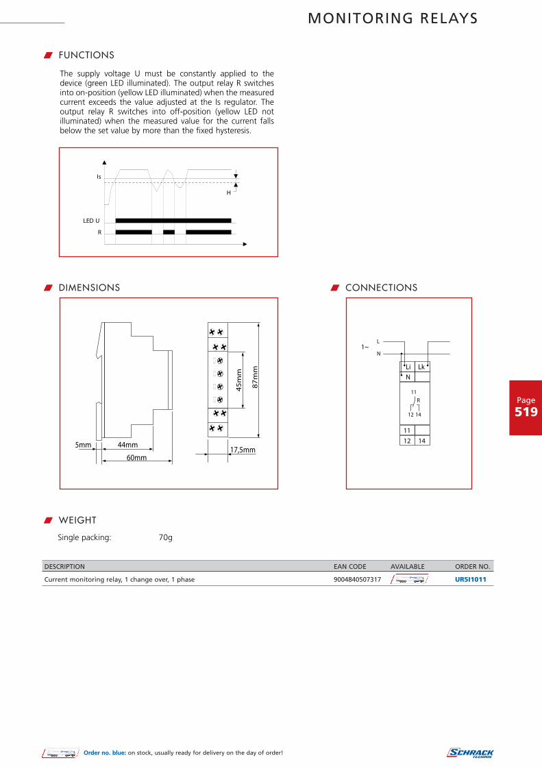
MONITORING RELAYS
Page
519
w CONNECTIONS
w WEIGHT
w DIMENSIONS
w FUNCTIONS
The supply voltage U must be constantly applied to the device (green LED illuminated). The output relay R switches into on-position (yellow LED illuminated) when the measured current exceeds the value adjusted at the Is regulator. The output relay R switches into off-position (yellow LED not illuminated) when the measured value for the current falls below the set value by more than the fixed hysteresis.
Single packing: 70g
DESCRIPTION EAN CODE AVAILABLE ORDER NO.
Current monitoring relay, 1 change over, 1 phase 9004840507317 UR5I1011
Order no. blue: on stock, usually ready for delivery on the day of order!

MONITORING RELAYS
Page
520
1. FunctionsAC/DC current monitoring in 1-phase mains with adjustablethresholds, timing for start-up suppression and tripping delay sep-arately adjustable and the following functions (selectable bymeans of rotary switch)OVER Overcurrent monitoringOVER+LATCH Overcurrent monitoring with
fault latchUNDER Undercurrent monitoringUNDER+LATCH Undercurrent monitoring with
fault latchWIN Monitoring the window
between Min and MaxWIN+LATCH Monitoring the window
between Min and Max withfault latch
2. Time rangesAdjustment range
Start-up suppression time: 0s 10sTripping delay: 0.1s 10s
3. IndicatorsGreen LED ON: indication of supply voltageGreen LED flashes: indication of start-up
suppression timeYellow LED ON/OFF: indication of relay outputRed LED ON/OFF: indication of failure of the
corresponding thresholdRed LED flashes: indication of tripping delay of
the corresponding threshold
4. Mechanical designSelf-extinguishing plastic housing, IP rating IP40 Mounted on DIN-Rail TS 35 according to EN 60715Mounting position: anyShockproof terminal connection according to VBG 4 (PZ1 required), IP rating IP20Tightening torque: max. 1NmTerminal capacity:
1 x 0.5 to 2.5 mm² with/without multicore cable end1 x 4 mm² without multicore cable end2 x 0.5 to 1.5 mm² with/without multicore cable end2 x 2.5 mm² flexible without multicore cable end
5. Input circuitSupply voltage:
24 to 240V AC/DC terminals A1-A2 (galvanicallyseparated)
Tolerance:24 to 240V DC -20% to +25%24 to 240V AC -15% to +10%
Rated frequency:24 to 240V AC 48 to 400Hz48 to 240V AC 16 to 48Hz
Rated consumption: 4.5VA (1W)Duration of operation: 100%Reset time: 500msWave form for AC: SinusResidual ripple for DC: 10%Drop-out voltage: >15% of the supply voltageOvervoltage category: III (in accordance with
IEC 60661-1)Rated surge voltage: 4kV
6. Output circuit2 potential free change-over contactsRated voltage: 250V ACSwitching capacity (distance <5 mm):
750VA (3A / 250V AC)Switching capacity (distance > 5mm):
1250VA (5A / 250V AC)Fusing: 5A fast actingMechanical life: 20 x 106 operationsElectrical life: 2 x 10⁵ operations at 1000VA
resistive loadSwitching frequency: max. 60/min at 100VA
resistive loadmax. 6/min at 1000VA resistive load(in accordance with IEC 60947-5-1)
Overvoltage category: III (in accordance with IEC 60664-1)
Rated surge voltage: 4kV
w TECHNICAL DATA
• AC/DC current monitoring in 1-phase mains• Multifunction• 16.6 to 400Hz• Fault latch• Zoom voltage 24 to 240V AC/DC• 2 change-over contacts• Width 22.5mm• Industrial design
w CURRENT MONITORING RELAY UR6I1052

MONITORING RELAYS
Page
521
7. Measuring circuitMeasured variable: DC or AC Sinus (16.6 to
400Hz)Input:
20mA AC/DC terminals K-I1(+)1A AC/DC terminals K-I2(+)5A AC/DC terminals K-I3(+)
Overload capacity:20mA AC/DC 250mA1A AC/DC 3A5A AC/DC 10A
Input resistance:20mA AC/DC 2.7Ω1A AC/DC 47mΩ5A AC/DC 10mΩ
Switching threshold:Max 10% to 100% of INMin 5% to 95% of IN
Overvoltage category: III (in accordance with IEC 60664-1)
Rated surge voltage: 4kV
8. AccuracyBase accuracy: ±5% (of maximum scale value)Frequency response: -10% to +5% (16.6 to 400Hz)
Adjustment accuracy: " 5% (of maximum scale value)
Repetition accuracy: " 2%Voltage influence: -
Temperature influence: " 0.1% / °C
9. Ambient conditionsAmbient temperature: -25 to +55°C (in accordance
with IEC 60068-1)-25 to +40°C (in accordancewith UL 508)
Storage temperature: -25 to +70°CTransport temperature: -25 to +70°CRelative humidity: 15% to 85% (in accordance
with IEC 60721-3-3 class 3K3)Pollution degree: 3 (in accordance with
IEC 60664-1)Vibration resistance: 10 to 55Hz 0.35mm (in accor-
dance with IEC 60068-2-6)Shock resistance: 15g 11ms (in accordance with
IEC 60068-2-27)
w FUNCTIONS
When the supply voltage U is applied, the output relays switchinto on-position (yellow LED illuminated) and the set interval ofthe startup suppression (START) begins (green LED U flashes).Changes of the measured current during this period do not affectthe state of the output relay. After the interval has expired thegreen LED is illuminated steadily. For all the functions the LEDsMIN and MAX are flashing alternating, when the minimum valuefor the measured current was chosen to be greater than the max-imum value
Overcurrent monitoring (OVER, OVER+LATCH)When the measured current exceeds the value adjusted at theMAXregulator, the set interval of the tripping delay (DELAY) begins(red LED MAX flashes). After the interval has expired (red LED MAXilluminated), the output relays switch into off-position (yellow LEDnot illuminated). The output relays again switch into on-position(yellow LED illuminated), when the measured current falls belowthe value adjusted at the MIN-regulator (red LED MAX not illumi-nated). If the fault latch is activated (OVER+LATCH) and the meas-ured current remains above the MAX-value longer than the setinterval of the tripping delay, the output relays remain in the off-position even if the measured current falls below the value adjust-ed at the MIN-regulator. After resetting the failure (interruptingand re-applying the supply voltage), the output relays switch intoon-position and a new measuring cycle begins with the set inter-val of the start-up suppression (START).
Undercurrent monitoring (UNDER, UNDER+LATCH)When the measured current falls below the value adjusted at theMIN-regulator, the set interval of the tripping delay (DELAY) begins(red LED MIN flashes). After the interval has expired (red LED MINilluminated), the output relays switch into off-position (yellow LEDnot illuminated). The output relays again switch into on-position(yellow LED illuminated), when the measured current exceeds thevalue adjusted at the MAX-regulator. If the fault latch is activated(UNDER+LATCH) and the measured current remains below theMIN-value longer than the set interval of the tripping delay, theoutput relays remain in the off-position even if the measured cur-rent exceeds the value adjusted at the MAX-regulator. After reset-ting the failure (interrupting and re-applying the supply voltage),the output relays switch into on-position and a new measuringcycle begins with the set interval of the start-up suppression(START).
LATCH
_<
_<
_<

MONITORING RELAYS
Page
522
Window function (WIN, WIN+LATCH)The output relays switch into on-position (yellow LED illuminated)when the measured current exceeds the value adjusted at theMINregulator. When the measured current exceeds the valueadjusted at the MAX-regulator, the set interval of the trippingdelay (DELAY) begins (red LED MAX flashes). After the interval hasexpired (red LED MAX illuminated), the output relays switch intooff-position (yellow LED not illuminated). The output relays againswitch into on-position (yellow LED illuminated) when the meas-ured current falls below the value adjusted at the MAX-regulator(red LED MAX not illuminated). When the measured current fallsbelow the value adjusted at the MINregulator, the set interval ofthe tripping delay (DELAY) begins again (red LED MIN flashes).After the interval has expired (red LED MIN illuminated), the out-put relays switch into off-position (yellow LED not illuminated).
If the fault latch is activated (WIN+LATCH) and the measured cur-rent remains below the MIN-value longer than the set interval ofthe tripping delay, the output relays remain in the off-position evenif the measured current exceeds the value adjusted at the MIN-reg-ulator. If the measured current remains above the MAX-valuelonger than the set interval of the tripping delay, the output relaysremain in the offposition even if the measured current falls belowthe value adjusted at the MAX-regulator. After resetting the failure(interrupting and reapplying the supply voltage), the output relaysswitch into on-position and a new measuring cycle begins with theset interval of the start-up suppression (START).
LATCH
LATCH

MONITORING RELAYS
DESCRIPTION EAN CODE AVAILABLE ORDER NO.
Current monitoring relay, 2 change over, 1 phase, 24-240V AC/DC 9004840557442 UR6I1052
Page
523
w CONNECTIONS
Range 20mA, supply voltage 24V AC/DC and fault latch
Range 5A, supply voltage 24V AC/DC without fault latch
Range 1A, supply voltage 230V AC and fault latch
15
16 18
25
26 28
24VAC/DC
15
16 18
25
26 28
24VAC/DC
15
16 18
25
26 28
w DIMENSIONS
Order no. blue: on stock, usually ready for delivery on the day of order!

MONITORING RELAYS
Page
524
w PHASE MONITORING RELAY UR5P3011
1. FunctionsMonitoring of phase sequence, phase failure and asymmetrywith adjustable asymmetry, connection of neutral wire optional.
2. Time rangesTripping delay: fixed, approx. 100 ms
3. IndicatorsGreen LED ON: indication of supply voltageYellow LED ON/OFF: indication of relay output
4. Mechanical designSelf-extinguishing plastic housing, IP rating IP40Mounted on DIN-Rail TS 35 according to EN 50022Mounting position: anyTightening torque: max. 1NmTerminal capacity:
1 x 0.5 bis 2.5 mm² with/without multicore cable end1 x 4 mm² without multicore cable end2 x 0.5 to 1.5 mm² with/without multicore cable end2 x 2.5 mm² flexible without multicore cable end
5. Input circuitSupply voltage: (= measured voltage)Terminals: (N)-L1-L2-L3Rated voltage Un: 3(N)~400/230V ACTolerance: -30% to +30% of Un
Rated consumption: 8 VA (0,8 W)Rated frequency: AC 48 to 63 HzDuty cycle: 100%Reset time: 500 msHold-up time: -Drop out voltage: >20% of the supply voltageOvervoltage category: III (according to IEC 60664-1)Rated surge voltage: 4 kV
6. Output circuit1 potential free change-over contactRated voltage: 250V ACSwitching capacity: 1250VA (5A / 250V)Fusing: 5A fast actingMechanical life: 20 x 106 operationsElectrical life: 2 x 10⁵ operations
at 1000VA resistive loadSwitching frequency: max. 60/min at 100VA resistive load
max. 6/min at 1000VA resistive load(according to IEC 60947-5-1)
Overvoltage category: III (according to IEC 60664-1)Rated surge voltage: 4kV
7. Measuring circuitMeasuring variable: 3(N)~, sinus, 48 to 63 HzMeasuring input: (=supply voltage)Terminals: (N)- L1- L2- L3Overload capacity: determined by tolerance
specified for supply voltageInput resistance: -Asymmetry: 5% to 25% adjustable,
or disengageableOvervoltage category: III (according to IEC 60664-1)Rated surge voltage: 4 kV
8. AccuracyBase accuracy: ±5% of maximum scale valueAdjustment accuracy: ≤5% of maximum scale valueRepetition accuracy: ±2%Voltage influence: -Temperature influence: ≤0.05% / ° C
9. Ambient conditionsAmbient temperature: -25 to +55°C (acc. to IEC 60068-1)Storage temperature: -25 to +70°CTransport temperature: -25 to +70°CRelative humidity: 15% to 85%
(acc. to IEC 60721-3-3 class 3K3)Pollution degree: 2, if built in 3 (acc. to IEC 60664-1)Vibration resistance: 10 to 55Hz 0.35 mm
(according to IEC 60068-2-6)Shock resistance: 15g 11ms (acc. to IEC 60068-2-27)
w TECHNICAL DATA
w SCHRACK-INFO
• Output relay• 1 potential free change over contact
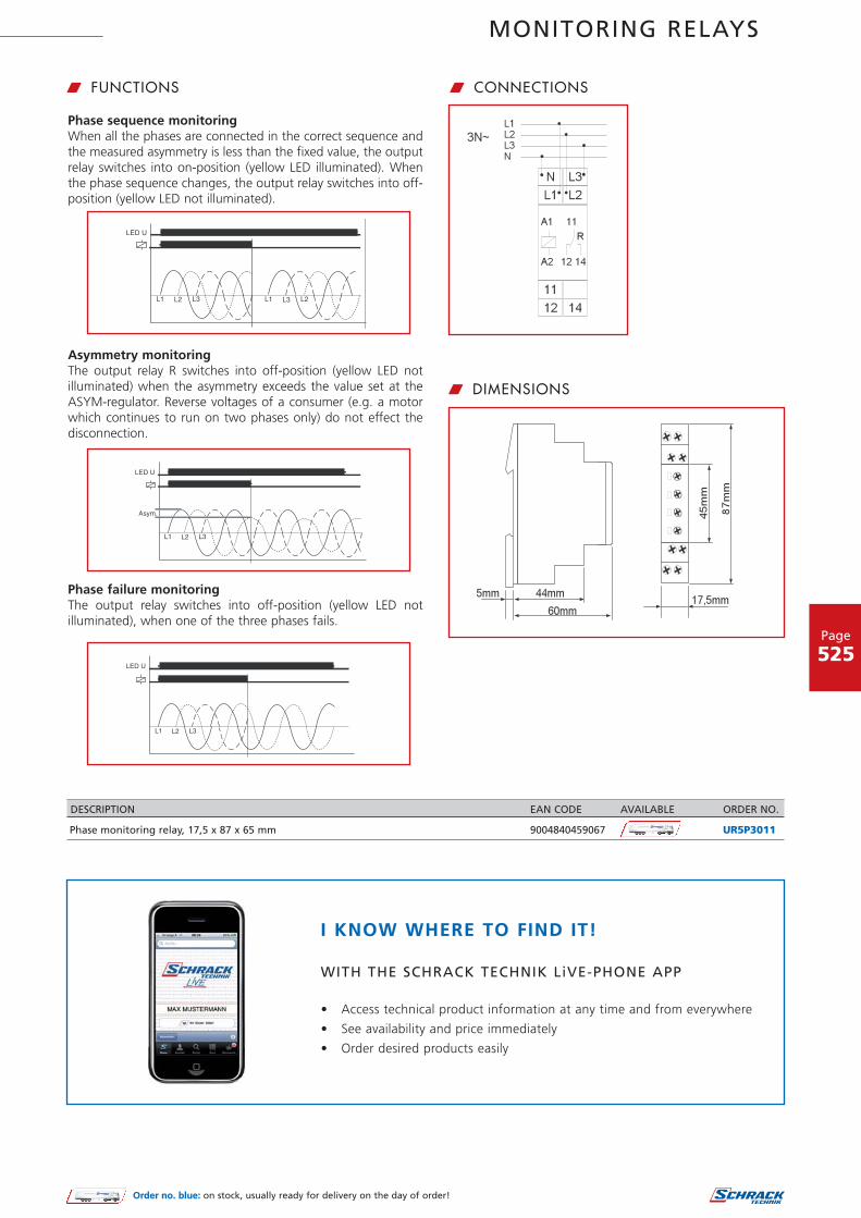
MONITORING RELAYS
Page
525
w FUNCTIONS
Phase sequence monitoringWhen all the phases are connected in the correct sequence andthe measured asymmetry is less than the fixed value, the outputrelay switches into on-position (yellow LED illuminated). Whenthe phase sequence changes, the output relay switches into off-position (yellow LED not illuminated).
Asymmetry monitoringThe output relay R switches into off-position (yellow LED not illuminated) when the asymmetry exceeds the value set at theASYM-regulator. Reverse voltages of a consumer (e.g. a motorwhich continues to run on two phases only) do not effect thedisconnection.
Phase failure monitoringThe output relay switches into off-position (yellow LED not illuminated), when one of the three phases fails.
w CONNECTIONS
w DIMENSIONS
L1 L2
11
A 12 14
A1
R
N L3
12 14
11
L1
2
L2L3N
3N~
17,5mm60mm
87mm
44mm5mm
45mm
DESCRIPTION EAN CODE AVAILABLE ORDER NO.
Phase monitoring relay, 17,5 x 87 x 65 mm 9004840459067 UR5P3011
Order no. blue: on stock, usually ready for delivery on the day of order!
I KNOW WHERE TO FIND IT!
WITH THE SCHRACK TECHNIK LiVE-PHONE APP
• Access technical product information at any time and from everywhere
• See availability and price immediately
• Order desired products easily

MONITORING RELAYS
Page
526
1. FunctionsMonitoring of phase sequence, phase failure and detection ofreturn voltage (by means of evaluating the asymmetry)
2. Time rangesAdjustment range
Start-up suppression time: fixed, max. 500msTripping delay: fixed, max. 350ms
3. IndicatorsGreen LED ON: indication of supply voltageYellow LED ON/OFF: indication of relay output
4. Mechanical designSelf-extinguishing plastic housing, IP rating IP40Mounted on DIN-Rail TS 35 according to EN 60715Mounting position: anyShockproof terminal connection according to VBG 4(PZ1 required), IP rating IP20Tightening torque: max. 1NmTerminal capacity:
1 x 0.5 bis 2.5 mm² with/without multicore cable end1 x 4 mm² without multicore cable end2 x 0.5 bis 1.5 mm² with/without multicore cable end2 x 2.5 mm² flexible without multicore cable end
5. Input circuitSupply voltage:
3(N)~ 400/230V terminals (N)-L1-L2-L3(= measuring voltage)
Tolerance:3(N)~ 400/230V 3(N)~ 342 to 457V
Rated frequency: 48 to 63HzRated consumption:
3(N)~ 400/230V 9VADuration of operation: 100%Reset time: 500msResidual ripple for DC: -Drop-out voltage: >20% of the supply voltageOvervoltage category: III (in accordance with IEC 60664-1)Rated surge voltage: 4kV
6. Output circuit2 potential free change-over contactsRated voltage: 250V ACSwitching capacity (distance <5 mm): 750VA (3A / 250V)Switching capacity (distance >5 mm): 1250VA (5A / 250V)Fusing: 5A fast actingMechanical life: 20 x 106 operationsElectrical life: 2 x 10⁵ operations
at 1000VA resistive loadSwitching frequency: max. 60/min at 100VA resistive load
max. 60/min at 1000VA resistive load(in accordance with IEC 60947-5-1)
Overvoltage category: III (in accordance with IEC 60664-1)Rated surge voltage: 4kV
7. Measuring circuitMeasured variable: AC Sinus, (48 to 63Hz)Input:
3(N)~ 400/230V terminals (N)-L1-L2-L3(= supply voltage)
Overload capacity:3(N)~ 400/230V 3(N)~ 457/264V
Input resistance:3(N)~ 400/230V 15k
Asymmetry: fixed, typ. 30%Overvoltage category: III (according to IEC 60664-1)Rated surge voltage: 4kV
8. AccuracyBase accuracy: -Frequency response: -Adjustment accuracy: -Repetition accuracy: -Voltage influence: -Temperature influence: -
w TECHNICAL DATA
• Voltage monitoring in 3-phase mains• Monitoring of phase sequence and phase failure• Detection of reverse voltage• Connection of neutral wire optional• Supply voltage = measuring voltage• 2 change-over contacts• Width 22.5 mm• Industrial design
w PHASE MONITORING RELAY UR6P3052

MONITORING RELAYS
9. Ambient conditionsAmbient temperature: -25 to +55°C
(in accordance with IEC 60068-1)-25 to +40°C(in accordance with UL 508)
Storage temperature: -25 to +70°CTransport temperature: -25 to +70°CRelative humidity: 15% to 85%
(in accordance withIEC 60721-3-3 class 3K3)
Pollution degree: 3 (in accordance with IEC 60664-1)Vibration resistance: 10 to 55Hz 0.35 mm
(in accordance withIEC 60068-2-6)
Shock resistance: 15g 11ms (in accordance withIEC 60068-2-27)
w FUNCTIONS
Phase sequence monitoringWhen all the phases are connected in the correct sequence andthe measured asymmetry is less than the fixed value, the outputrelays switch into on-position (yellow LED illuminated). When thephase sequence changes, the output relays switch into off-positi-on (yellow LED not illuminated).
Phase failure monitoringWhen one of the three phases fails, the output relays switch intooff-position (yellow LED not illuminated).
Detection of reverse voltage(by means of evaluation of asymmetry)The output relays switch into off-position (yellow LED not illumi-nated) when the asymmetry between the phase voltages exceedsthe fixed value of the asymmetry. An asymmetry caused by thereverse voltage of a consumer (e.g. a motor which continues torun on two phases only) does not effect the disconnection.
w CONNECTIONS
w DIMENSIONS
DESCRIPTION EAN CODE AVAILABLE ORDER NO.
Phase monitoring relay, 2 change over, 3 phases, industrial design 9004840557428 UR6P3052
Page
527
Order no. blue: on stock, usually ready for delivery on the day of order!

MONITORING RELAYS
Page
528
1. FunctionsTemperature monitoring of the motor winding (max. 6 PTC) with fault latch for temperature sensors in accordance with DIN 44081, short circuit monitoring of the thermistor line (selectable by means of terminals), integrated test/reset key.
2. Time rangesAdjustment range
Start-up suppression time (Start): -Tripping delay (Delay): -
3. IndicatorsGreen LED ON: indication of supply voltageRed LED ON/OFF: indication of failure
4. Mechanical designSelf-extinguishing plastic housing, IP rating IP40Mounted on DIN-Rail TS 35 according to EN 50022Mounting position: anyShockproof terminal connection according to VBG 4 (PZ1 required), IP rating IP20Tightening torque: max. 1NmTerminal capacity:
1 x 0.5 to 2.5mm² with/without mulitcore cable end1 x 4mm² without mulitcore cable end2 x 0.5 to 1.5mm² with/without mulitcore cable end2 x 2.5mm² flexible without mulitcore cable end
5. Input voltageSupply voltage: 230V ACTerminals: A1-A2Rated voltage Un: see table ordering information or
printing on the unitTolerance: -15% to +10% of UnRated consumption: 1,3VA (1W)Rated frequency: AC 48 to 63HzDuty cycle: 100%Reset time: 250msResidual ripple for DC: 50msDrop-out voltage: >30% of the supply voltageOvervoltage category: III (in accordance with IEC 60664-1)Rated surge voltage: 6kV
6. Output circuit1 potential free change over contactTerminals: 11-12-14Rated voltage: 250V ACSwitching capacity: 1250VA AC1 B300/P300
(in accordance with IEC 60947-5-1); therm. constant current 5A
Fusing: 5A fast actingMechanical life: 20 x 106 operationsElectrical life: 2 x 10⁵ operations
at 1000VA resistive loadSwitching frequency: max. 6/min at 1000VA resistive load
(in accordance with IEC 60947-5-1)Overvoltage category III. (in accordance with IEC 60664-1)Rated surge voltage: 6kV
7. Measuring circuitTerminals: T1-T2 or T1-T3Initial resistance: <1.5kResponse value (relay in off-position): 3.6kRelease value (relay in on-position): 1.65kDisconnection (short circuit thermistor): yes at T1-T2
no at T1-T3Measuring voltage T1-T2: 7.5V at R 4.0k
(in accordance withEN 60947-8)
Overvoltage category: III (in accordance with IEC 60664-1)
Rated surge voltage: 6kV
8. Control contact RFunction: connection of an external reset keyLoadable: noLine length R1-R2: max. 10m (twisted pair)Control pulse length: min. 50msReset: potential free normally open contact, terminals R1-R2Note: The terminals R2-T2 are internal af liated with each other!!
9. AccuracyBase accuracy: ±5%Adjustment accuracy -Repetition accuracy: 1%Voltage influence: -Temperature influence: 0.15% / °C
10. Ambient conditionsAmbient temperature: -25 to +55°CStorage temperature: -25 to +70°CTransport temperature: -25 to +70°CRelative humidity: 15% to 85%
(in accordance with IEC 60721-3-3 class 3K3)Pollution degree: 2, if built in 3
(in accordance with IEC 60664-1)
11. WeightSingle packing: 137,20g
Tripping unit for temperature monitoring of the motor winding with and
Optional evaluation of one thermal contactTest function with integrated reset keyRated isolated voltage on the sensor circuit up to 690V1 change over contactWidth 35mmInstallation design
circuit monitoring of the thermistor line (selectable by means of terminals)without short
w TECHNICAL DATA
w SCHRACK-INFO
w THERMISTOR MONITORING RELAY UR5R1021

MONITORING RELAYS
Page
529
w CONNECTIONS w DIMENSIONS
w FUNCTIONS
Temperature monitoring of the motor winding with fault latchIf the supply voltage U is applied (green LED illuminated) and the cumu-lative resistance of the PTC-circuit is less than 3.6k (standard tempera-ture of the motor), the output relay switches into on-position. Pressing the test/reset key under this conditions forces the output relay to switch into off-position. It remains in state as long as the test/reset key is pressed and thus the switching function can be checked in case of fault. The test function is not effective by using an external reset key.When the comulative resistance of the PTC-circuit exceeds 3.6k (at least one of the PTCs has reached the cut-off temperature), the output relay switches into off-position (red LED illuminated). The output relay switches into on-position again (red LED not illumina-ted), if the cumulative resistance drops below 1.65k by cooling down of the PTC and either a reset key (internal or external) was pressed or the supply voltage was disconnected and re-applied.
Note:Only one of this circuit versions (either monitoring of the temperature sensor or monitoring of the thermal contact) can be executed!!
MonitoringTemperature sensor
MonitoringThermal contact
Application of an external Reset
Application of internal Test/Reset - key
35mm44mm
60mm
5mm
87mm
45mm
T2
12 14
R
11
A1
12 14
A1
A2
T3 A2T1
U
R2R1
Reset
11
T2
12 14
R
11
A1
12 14
A1
A2
T3 A2T1
U
R2R1
Reset
11
DESCRIPTION EAN CODE AVAILABLE ORDER NO.
Thermistor monitoring relay, 1 change over, input 230V 9004840515091 UR5R1021
Order no. blue: on stock, usually ready for delivery on the day of order!
I KNOW WHERE TO FIND IT!
THE SCHRACK TECHNIK WEB SHOP WITH NAVIGATORWWW.SCHRACK.COM
• Finding product information made easy
• Buying products around the clock
• Quick access customer service

MONITORING RELAYS
Page
530
1. FunctionsTemperature monitoring of the motor winding (max. 6 PTC) withfault latch, for temperature probes in accordance with DIN 44081Test function with integrated test/reset key
2. Time rangesAdjustment range
Start-up suppression time: -Tripping delay: -
3. IndicatorsGreen LED ON: indication of supply voltageRed LED ON/OFF: indication of failure
4. Mechanical designSelf-extinguishing plastic housing, IP rating IP40Mounted on DIN-Rail TS 35 according to EN 60715Mounting position: anyShockproof terminal connection according to VBG 4 (PZ1 required), IP rating IP20Tightening torque: max. 1NmTerminal capacity:
1 x 0.5 to 2.5 mm² with/without multicore cable end1 x 4 mm² without multicore cable end2 x 0.5 to 1.5 mm² with/without multicore cable end2 x 2.5 mm² flexible without multicore cable end
5. Input circuitSupply voltage:
24 to 240V AC/DC terminals A1-A2 (galvanically sep-arated)
Tolerance:24 to 240V DC -20% to +25%24 to 240V AC -15% to +10%
Rated frequency:24 to 240V AC 48 to 400Hz48 to 240V AC 16 to 48Hz
Rated consumption: 4.5VA (1W)Duration of operation: 100%Reset time: 500msWave form for AC: SinusResidual ripple for DC: 10%Drop-out voltage: >15% of the supply voltageOvervoltage category: III (in accordance with
IEC 60661-1)Rated surge voltage: 4kV
6. Output circuit2 potential free change-over contactsRated voltage: 250V ACSwitching capacity (distance <5 mm): 750VA (3A / 250V AC)Switching capacity (distance >5 mm): 1250VA (5A / 250V AC)Fusing: 5A fast actingMechanical life: 20 x 106 operationsElectrical life: 2 x 10⁵ operations
at 1000VA resistive loadSwitching frequency: max. 60/min at 100VA resistive
loadmax. 6/min at 1000VA resistiveload (in accordance with IEC 60947-5-1)
Overvoltage category: III (in accordance with IEC 60664-1)
Rated surge voltage: 4kV
7. Measuring circuitInput: terminals T1-T2Initial resistance: <1.5kΩResponse value (relay in off-position): " 3.6kΩRelease value (relay in on-position): " 1.8kΩDisconnection (short circuit thermistor): no
Measuring voltage T1-T2: " 2.5V DC at R " 4.0ksΩ(in accordance with DIN VDE 0660 part 302)
Overvoltage category: III (in accordance with IEC 60664-1)Rated surge voltage: 4kV
8. Control contact RFunction: external reset keyLoadable: noLine length R-T2: max. 10m (twisted pair)Control pulse length: -Reset: potential free normally open con-
tact, terminals R-T2
9. AccuracyBase accuracy: ±10% (of maximum scale value)Frequency response: -Adjustment accuracy: -
Repetition accuracy: " 1%
Voltage influence: " 2.2%
w TECHNICAL DATA
• Temperature monitoring of the motor winding• Zoom voltage 24 to 240V AC/DC• 2 change-over contacts• External reset key connectable• Width 22.5mm• Industrial design
w THERMISTOR MONITORING RELAY UR6R1052
_<
_<
_<
_<
_<
240V AC/DC
• 2 change-over contacts• External reset key connectable• Width 22.5mm• Industrial design

MONITORING RELAYS
Temperature influence: " 0.1% / °C10. Ambient conditionsAmbient temperature: -25 to +55°C
(in accordance with IEC 60068-1)-25 to +40°C (in accordance with UL 508)
Storage temperature: -25 to +70°CTransport temperature: -25 to +70°CRelative humidity: 15% to 85%
(in accordance with IEC 60721-3-3class 3K3)
Pollution degree: 3 (in accordance with IEC 60664-1)Vibration resistance: 10 to 55Hz 0.35mm
(in accordance with IEC 60068-2-6)
Shock resistance: 15g 11ms(in accordance with IEC 60068-2-27)
w FUNCTIONS
If the supply voltage U is applied (green LED illuminated) and thecumulative resistance of the PTC-circuit is less than 3.6kΩ (stan-dard temperature of the motor), the output relays switch into on-position. Pressing the test/reset key under this conditions forcesthe output relays to switch into off-position. They remain in thisstate as long as the test/reset key is pressed and thus the switch-ing function can be checked in case of fault. The test function isnot effective using an external reset key. When the cumulativeresistance of the PTC-circuit exceeds 3.6kΩ (at least one of thePTCs has reached the cut-off temperature), the output relaysswitch into off-position (red LED illuminated). The output relaysagain switch into on-position (red LED not illuminated), if thecumulative resistance drops below 1.8kΩ by cooling down of thePTC and either a reset key (internal or external) was pressed or thesupply voltage was disconnected and re-applied.
w CONNECTIONS w DIMENSIONS
DESCRIPTION EAN CODE AVAILABLE ORDER NO.
Thermistor monitoring relay, 2 change over, 24-240V AC/DC, industrial design 9004840557411 UR6R1052
Page
531
Order no. blue: on stock, usually ready for delivery on the day of order!
_<

MONITORING RELAYS
Page
532
1. FunctionsLevel monitoring of conductive liquid, timing for tripping delay and turn-off delay seperatly adjustable and the following functions (selectable by means of rotary switch):Pump up pump up or minimum monitoringPump down pump down or maximum monitoring
2. Time rangesAdjustment range
Tripping delay (Delay ON): 0.5s to 10sTurn-off delay (Delay OFF): 0.5s to 10s
3. IndicatorsGreen LED ON: indication of supply voltageYellow LED ON/OFF: indication of output relay
4. Mechanical designSelf-extinguishing plastic housing, IP rating IP40Mounted on DIN-rail TS 35 according to EN 50022Mounting position: anyShockproof terminal connection according to VBG 4 (PZ1 required), IP rating IP20Tightening torque: max. 1NmTerminal capacity:
1 x 0.5 to 2.5mm² with/without multicore cable end1 x 4mm² without multicore cable end2 x 0.5 to 1.5mm² with/without multicore cable end2 x 2.5mm² flexible without multicore cable end
5. Input circuitTerminals: A1-A2Rated voltage Un: see table ordering information or
printing on the unitTolerance: -15% of +10% of UnRated consumption: 2VA (1.0W)Rated frequency: AC 48 to 63HzDuty cycle: 100%Reset time: 500msHold-up time: -Drop-out voltage: >30% of supply voltageOvervoltage category: III (in accordance with IEC 60664-1)Rated surge voltage: 6kV
6. Output circuit1 potential free change over contactRated voltage: 250V ACSwitching capacity: 1250VAAC1 B300/P300
(in accordance with IEC 60947-5-1)therm. constant current 5A
Fusing: 5A fast actingMechanical life: 20 x 106 operationsElectrical life: 2 x 10⁵ operations
at 1000VA resistive loadSwitching frequency: max. 6/min at 1000VA resistive load
(in accordance with IEC 60947-5-1)Overvoltage category: III. (in accordance with IEC 60664-1)Rated surge voltage: 6kV
7. Measuring circuitMeasuring input: conductive probes
(Type SK1, SK2, SK3)Terminals: E1-E2-E3Sensitivity: 0,25 to 100k (4mS to 10 S)Sensor voltage: 12V ACSensor current: max. 7mAWiring distance (capacity of cable 100nF/km):
max. 1000m (set value <50%)max. 100m (set value 100%)
Overvoltage category: III (in accordance with IEC 60664-1)Rated surge voltage: 6kV
8. AccuracyBase accuracy: -Adjusting accuracy: -Repetition accuracy: -Voltage influence: -Temperature influence: -
9. Ambient conditionsAmbient temperature: -25 to +55°CStorage temperature: -25 to +70°CTransport temperature: -25 to +70°CRelative humidity: 15% to 85%
(in accordance with IEC 60721-3-3 class 3K3)Pollution degree: 2, if built in 3
(in accordance with IEC 60664-1)
10. WeightSingle packing: 140g
Level monitoring of conductive liquids
Multifunction
Secure isolation of the measuring circuit
1 change over contact
Width 35mm
Installation design
w TECHNICAL DATA
w SCHRACK-INFO
w LEVEL MONITORING RELAY UR5L1021

MONITORING RELAYS
Page
533
w CONNECTIONS w DIMENSIONS
w FUNCTIONS
Pump upConnection of the probe rods E1, E2 and E3. Alternatively the electri-cally conducting container can be connected in lieu of the test probe E3. When the air-fluid level falls below the minimum probe E2 the set interval of tripping delay (Delay ON) begins. After the expiration of the interval, the output relays R switches into on-position (yellow LED illuminated). When the air-fluid level again rises above the maximum probe E1, the set interval of turn-off delay (Delay OFF) begins. After the expiration of the interval the output relays R switches into off-position (yellow LED not illuminated).
Pump downConnection of the probe rods E1, E2 and E3. Alternatively the electrically conducting container can be connected in lieu of the test probe E3.When the maximum probe E1 gets moistened the set interval of tripping delay (Delay ON) begins. After the expiration of the interval the output relays R switches into on-position (yellow LED illuminated). When the air-fluid level falls below the minimum probe E2, the set interval of turn-off delay (Delay OFF) begins. After the expiration of the interval, the output relays R switches into off-position (yellow LED not illuminated).
Minimum monitoring (Pump up)Connection the probe rods E2 and E3 (bridge E1-E3). Alternatively the electrically conducting container can be connected in lieu of the test probe E3. When the air-fluid level falls below the probe E2 the set interval of trip-ping delay (Delay ON) begins. After the expiration of the interval, the output relays R switches into on-position (yellow LED illuminated). When the air-fluid level again rises above the probe E2, the set interval of turn-off delay (Delay OFF) begins. After the expiration of the interval the out-put relays R switches into off-position (yellow LED not illuminated).
Maximum monitoring (Pump down)Connection of probe rods E2 and E3 (bridge E1-E3). Alternatively the electrically conducting container can be connected in lieu of the test probe E3.When the probe E2 gets moistened the set interval of tripping delay (Delay ON) begins. After the expiration of the interval the output relays R switches into on-position (yellow LED illuminated). When the air-fluid level sinks below the probe E2, the set interval of turn-off delay (Delay OFF) begins. After the expiration of the interval the output relays R swit-ches into off-position (yellow LED not illuminated).
U
Probe E1
Probe E2
Probe E3
Leve
l
U
Probe E1
Probe E2
Probe E3
Leve
l
NoteUse cables with low capacity for wiring the probes especially with extended wiring length.
Following processes are suggested for the adjustment:
- The existent time delay should be to minimum (0,5s).- The function selector switch must be in position pump down.
- Turn the sensitivity controller slowly clockwise from min to max until the relais switches into on-position. (probes must be in dipped state)- The moistened probes should be taken out of the liquid to control if the relais switches into off-position. If the relais doesn't switch into off-position, turn the sensitivity controller slightly back to min. (counter clockwise)
- Set the existent time delay to desired value to fade out a short term moisten the probes by waves in the liquid.- Set the function selector switch to desired position. (either pump up or pump down)
U
Probe E1
Probe E2
Probe E3
Leve
l
U
Probe E1
Probe E2
Probe E3
Leve
l
U
Probe E2
Probe E3
Leve
l
U
Probe E2
Probe E3
Leve
l
E2
15
16 18
R
16
LN
E3
18 15
A1
A2
Mass probe
Probemin.
Probemax.
A1 A2E1
35mm44mm
60mm
5mm
87mm
45mm
DESCRIPTION EAN CODE AVAILABLE ORDER NO.
Level monitoring relay, 1 change over 9004840515084 UR5L1021
Single probe 9004840519655 URL91010
Level sensor, 1 rod 9004840203264 URL90010
Level sensor, 2 rods 9004840203271 URL90020
Level sensor, 3 rods 9004840203288 URL90030
Order no. blue: on stock, usually ready for delivery on the day of order!
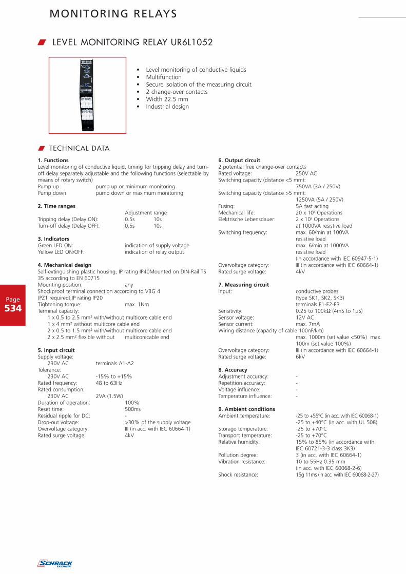
MONITORING RELAYS
Page
534
w LEVEL MONITORING RELAY UR6L1052
1. FunctionsLevel monitoring of conductive liquid, timing for tripping delay and turn-off delay separately adjustable and the following functions (selectable bymeans of rotary switch)Pump up pump up or minimum monitoringPump down pump down or maximum monitoring
2. Time rangesAdjustment range
Tripping delay (Delay ON): 0.5s 10sTurn-off delay (Delay OFF): 0.5s 10s
3. IndicatorsGreen LED ON: indication of supply voltageYellow LED ON/OFF: indication of relay output
4. Mechanical designSelf-extinguishing plastic housing, IP rating IP40Mounted on DIN-Rail TS35 according to EN 60715Mounting position: anyShockproof terminal connection according to VBG 4(PZ1 required),IP rating IP20Tightening torque: max. 1NmTerminal capacity:
1 x 0.5 to 2.5 mm² with/without multicore cable end1 x 4 mm² without multicore cable end2 x 0.5 to 1.5 mm² with/without multicore cable end2 x 2.5 mm² flexible without multicorecable end
5. Input circuitSupply voltage:
230V AC terminals A1-A2Tolerance:
230V AC -15% to +15%Rated frequency: 48 to 63HzRated consumption:
230V AC 2VA (1.5W)Duration of operation: 100%Reset time: 500msResidual ripple for DC: -Drop-out voltage: >30% of the supply voltageOvervoltage category: III (in acc. with IEC 60664-1)Rated surge voltage: 4kV
6. Output circuit2 potential free change-over contactsRated voltage: 250V ACSwitching capacity (distance <5 mm):
750VA (3A / 250V)Switching capacity (distance >5 mm):
1250VA (5A / 250V)Fusing: 5A fast actingMechanical life: 20 x 106 OperationsElektrische Lebensdauer: 2 x 10⁵ Operations
at 1000VA resistive loadSwitching frequency: max. 60/min at 100VA
resistive loadmax. 6/min at 1000VA resistive load(in accordance with IEC 60947-5-1)
Overvoltage category: III (in accordance with IEC 60664-1)Rated surge voltage: 4kV
7. Measuring circuitInput: conductive probes
(type SK1, SK2, SK3)terminals E1-E2-E3
Sensitivity: 0.25 to 100k (4mS to 1μS)Sensor voltage: 12V ACSensor current: max. 7mAWiring distance (capacity of cable 100nF/km)
max. 1000m (set value <50%) max.100m (set value 100%)
Overvoltage category: III (in accordance with IEC 60664-1)Rated surge voltage: 6kV
8. AccuracyAdjustment accuracy: -Repetition accuracy: -Voltage influence: -Temperature influence: -
9. Ambient conditionsAmbient temperature: -25 to +55°C (in acc. with IEC 60068-1)
-25 to +40°C (in acc. with UL 508)Storage temperature: -25 to +70°CTransport temperature: -25 to +70°CRelative humidity: 15% to 85% (in accordance with
IEC 60721-3-3 class 3K3)Pollution degree: 3 (in acc. with IEC 60664-1)Vibration resistance: 10 to 55Hz 0.35 mm
(in acc. with IEC 60068-2-6)Shock resistance: 15g 11ms (in acc. with IEC 60068-2-27)
w TECHNICAL DATA
• Level monitoring of conductive liquids• Multifunction• Secure isolation of the measuring circuit• 2 change-over contacts• Width 22.5 mm• Industrial design

Order no. blue: on stock, usually ready for delivery on the day of order!
Page
535
MONITORING RELAYS
w FUNCTIONS
Pump upConnection of the probe rods E1, E2 and E3. Alternatively the electricallyconducting container can be connected in lieu of the test probe E3.Whenthe air-fluid level falls below the minimum probe E2 the set interval of thetripping delay (DELAY ON) begins. After the expiration of the interval theoutput relays switch into on-position (yellow LED illuminated). When theair-fluid level again rises above the maximum probe E1, the set interval ofthe turn-off delay (DELAY OFF) begins. After the expira-tion of the inter-val the output relays switch into off-position (yellow LED not illuminated).
Minimum monitoring (Pump up)Connection of probe rods E2 and E3 (Bridge E1-E3). Alternatively the elec-trically conducting container can be connected in lieu of the test probe E3.When the air-fluid level falls below the probe E2 the set interval of the trip-ping delay (DELAY ON) begins. After the expiration of the interval the out-put relays switch into on-position (yellow LED illuminated). When the air-fluid level again rises above the probe E2, the set interval of the turn-offdelay (DELAY OFF) begins. After the expiration of the interval the outputrelays switch into off-position (yellow LED not illuminated).
Pump downConnection of the probe rods E1, E2 and E3. Alternatively the electricallyconducting container can be connected in lieu of the test probe E3.Whenthe maximum probe E1 gets moistened the set interval of the trip-pingdelay (DELAY ON) begins. After the expiration of the interval the outputrelays switch into on-position (yellow LED illuminated). When the air-fluidlevel falls below the minimum probe E2, the set interval of the turn-offdelay (DELAY OFF) begins. After the expiration of the interval the outputrelays switch into off-position (yellow LED not illuminated).
Maximum monitoring (Pump down)Connection of probe rods E2 and E3 (Bridge E1-E3). Alternatively the elec-trically conducting container can be connected in lieu of the test probe E3.When the probe E2 gets moistened the set interval of the tripping delay(DELAY ON) begins. After the expiration of the interval the output relaysswitch into on-position (yellow LED illuminated). When the air-fluid levelsinks below the probe E2, the set interval of the turn-off delay (DELAYOFF) begins. After the expiration of the interval the output relays switchinto off-position (yellow LED not illuminated).
w NOTEUse cables with low capacity for wiring the probes especially with extended wiring length.Following processes are suggested for the adjustment:- The existent time delay should be to minimum (0,5s).- The function selector switch must be in position pump down.- Turn the sensitivity controller slowly clockwise from min to max until the relais switch into on-position. (probes must be in dipped state)- The moistened probes should be taken out of the liquid to control if the relais switch into off-position. If the relais doesn't switch into off-position,
turn the sensitivity controller slightly back to min. (counter clockwise)- Set the existent time delay to desired value to fade out a short term moisten the probes by waves in the liquid.- Set the function selector switch to desired position (either pump up or pump down)
U
Probe E1
Probe E2
Probe E3
Leve
l
U
Probe E1
Probe E2
Probe E3
Leve
l
U
Probe E2
Probe E3
Leve
l
U
Probe E2
Probe E3
Leve
l
w CONNECTIONS w DIMENSIONS
15
16 18
15
16 18
E1 E2 E3
L1N
A1
A2
25
26 28
25
26 28
Massesonde
Sonde min.
Sonde max.
DESCRIPTION EAN CODE AVAILABLE ORDER NO.
Level monitoring relay, 2 change over 9004840557435 UR6L1052
Single probe 9004840519655 URL91010
Level sensor, 1 rod 9004840203264 URL90010
Level sensor, 2 rods 9004840203271 URL90020
Level sensor, 3 rods 9004840203288 URL90030