topic: choppers subject: power electronics(ee-309) class: 5 th sem. (ee) presented by: er. ram singh...
TRANSCRIPT

Punjab EDUSAT Society 1
Topic: ChoppersSubject: Power Electronics(EE-309)
Class: 5th sem. (EE)
Presented By:Er. Ram Singh(Asstt. Prof.) Deptt. Of EE
BHSBIET Lehragaga
Punjab EDUSAT Society 2
Introduction
• Chopper is a static device.• A variable dc voltage is obtained from a
constant dc voltage source.• Also known as dc-to-dc converter.• Widely used for motor control.• Also used in regenerative braking.• Thyristor converter offers greater efficiency,
faster response, lower maintenance, smaller size and smooth control.
Punjab EDUSAT Society 3
Types of Choppers
Step-down choppers. Step-up choppers.
In step down chopper output voltage is less than input voltage.
In step up chopper output voltage is more than input voltage.
Punjab EDUSAT Society 4
Principle Of Step-down Chopper
V
i0
V 0
C hopper
R
+

Punjab EDUSAT Society 5
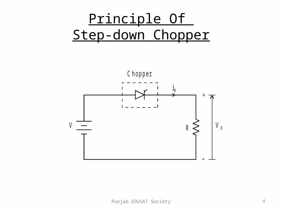
• A step-down chopper with resistive load. • The thyristor in the circuit acts as a switch.• When thyristor is ON, supply voltage appears
across the load • When thyristor is OFF, the voltage across the
load will be zero.

Punjab EDUSAT Society 6
V d c
v 0
V
V /R
i0
Id c
t
t
tO N
T
tO F F

Punjab EDUSAT Society 7
verage value of output or load voltage.
verage value of output or load current.
Time interval for which SCR conducts.
Time interval for which SCR is OFF.
Period of switching
dc
dc
ON
OFF
ON OFF
V A
I A
t
t
T t t
or chopping period.
1 Freq. of chopper switching or chopping freq.f
T
Punjab EDUSAT Society 8
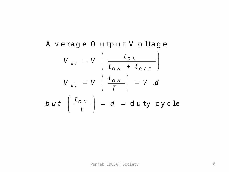
Average Output Voltage
.
duty cycle
ONdc
ON OFF
ONdc
ON
tV V
t t
tV V V d
T
tbut d
t
Punjab EDUSAT Society 9
2
0
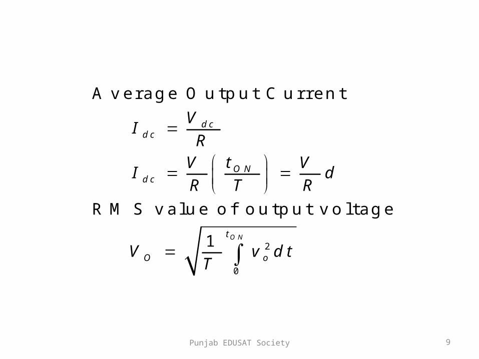
Average Output Current
RMS value of output voltage
1 ON
dcdc
ONdc
t
O o
VI
RtV V
I dR T R
V v dtT

Punjab EDUSAT Society 10
2
0
2
But during ,
Therefore RMS output voltage
1
.
.
ON
ON o
t
O
ONO ON
O
t v V
V V dtT
tVV t V
T T
V d V
Punjab EDUSAT Society 11
2
2
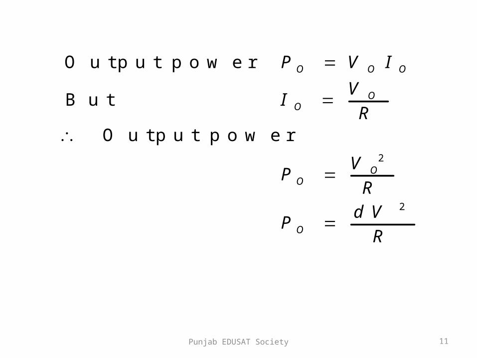
Output power
But
Output power
O O O
OO
OO
O
P V I
VI
R
VP
R
dVP
R
Punjab EDUSAT Society 12
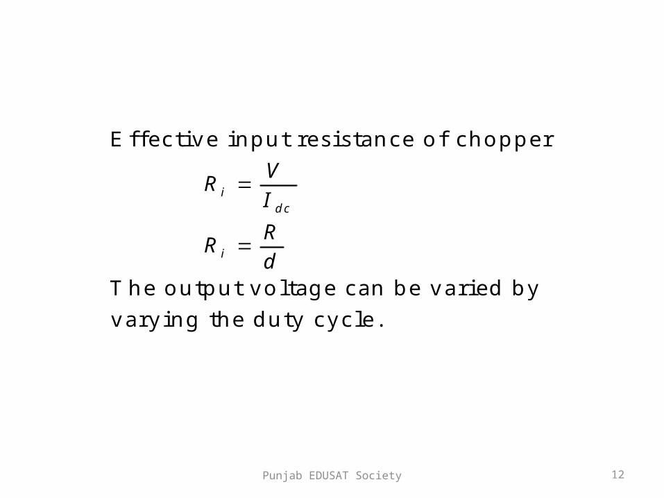
Effective input resistance of chopper
The output voltage can be varied by
varying the duty cycle.
idc
i
VR
I
RR
d
Punjab EDUSAT Society 13
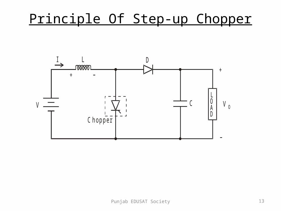
Principle Of Step-up Chopper
+
V OV
C hopper
CLOAD
DLI
+

Punjab EDUSAT Society 14
• Step-up chopper is used to obtain a load voltage higher than the input voltage V.
• The values of L and C are chosen depending upon the requirement of output voltage and current.
• When the chopper is ON, the inductor L is connected across the supply.
• The inductor current ‘I’ rises and the inductor stores energy during the ON time of the chopper, tON.

Punjab EDUSAT Society 15
• When the chopper is off, the inductor current I
is forced to flow through the diode D and load
for a period, tOFF.
• The current tends to decrease resulting in
reversing the polarity of induced EMF in L.
• Therefore voltage across load is given by:-

Punjab EDUSAT Society 16
. ., O O
dIV V L i e V V
dt
Punjab EDUSAT Society 17
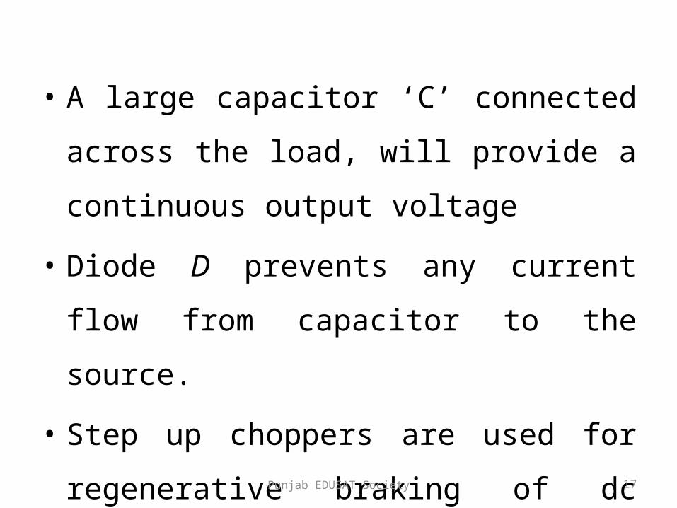
• A large capacitor ‘C’ connected across the
load, will provide a continuous output voltage
• Diode D prevents any current flow from
capacitor to the source.
• Step up choppers are used for regenerative
braking of dc motors
Punjab EDUSAT Society 18
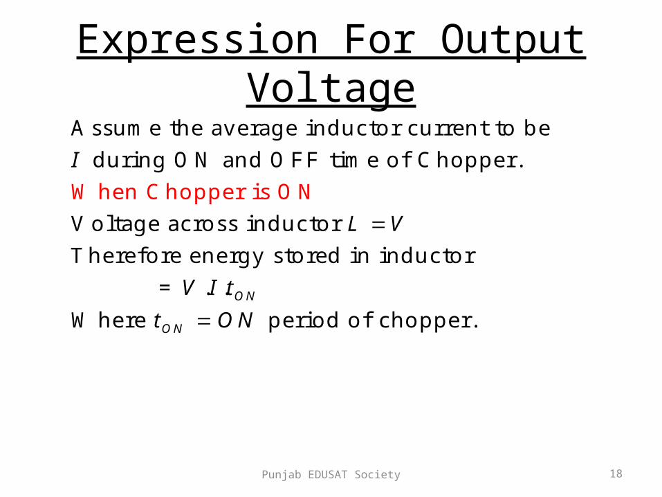
Expression For Output VoltageAssume the average inductor current to be
during ON and OFF time of Chopper.
Voltage across inductor
Therefore energy stored in inductor
= . .
Where
When Chopper
period of chopper.
is ON
ON
ON
I
L V
V I t
t ON

Punjab EDUSAT Society 19
(energy is supplied by inductor to load)
Voltage across
Energy supplied by inductor
where period of Chopper.
Neg
When Chopper
lecting losses, energy stored in inductor
is OFF
O
O OFF
OFF
L V V
L V V It
t OFF
L
= energy supplied by inductor L
Punjab EDUSAT Society 20
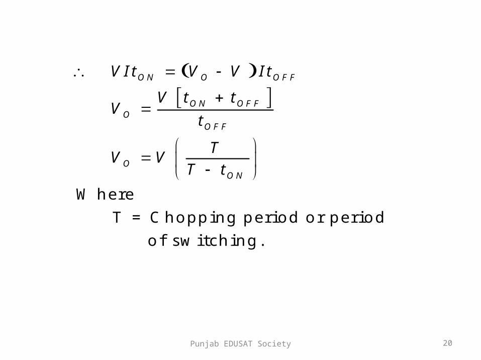
Where
T = Chopping period or period
of switching.
ON O OFF
ON OFFO
OFF
OON
VIt V V It
V t tV
t
TV V
T t
Punjab EDUSAT Society 21
1
1
1
1
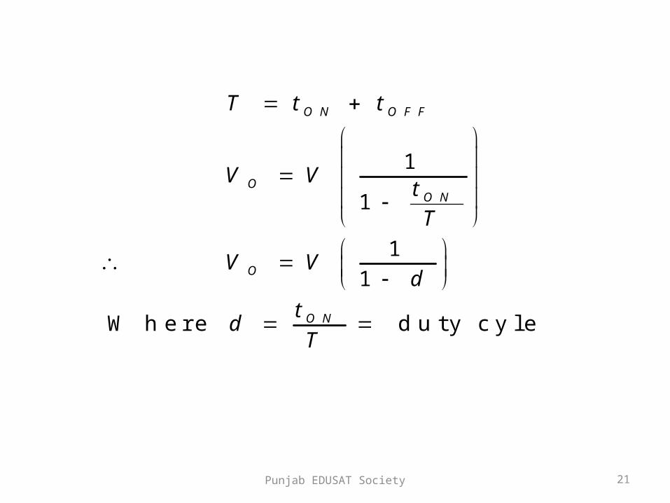
Where duty cyle
ON OFF
OON
O
ON
T t t
V Vt
T
V Vd
td
T
Punjab EDUSAT Society 22
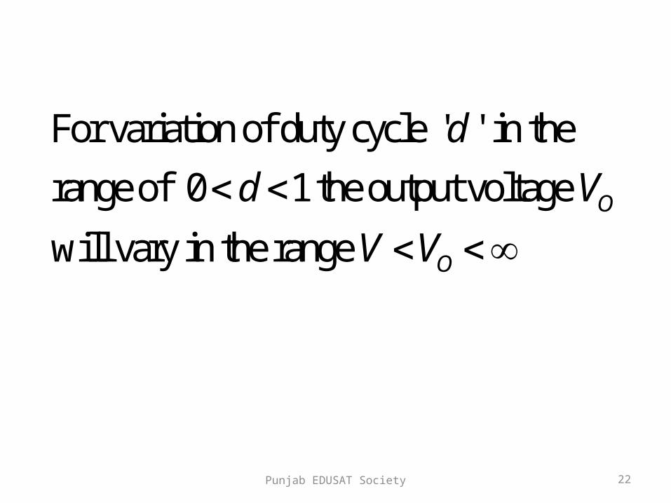
For variation of duty cycle ' ' in the
range of 0 1 the output voltage
will vary in the range O
O
d
d V
V V

Punjab EDUSAT Society 23
Control Strategies
• The output dc voltage can be varied by the
following methods.
1. Pulse width modulation control or constant
frequency operation.
2. Variable frequency control

Punjab EDUSAT Society 24
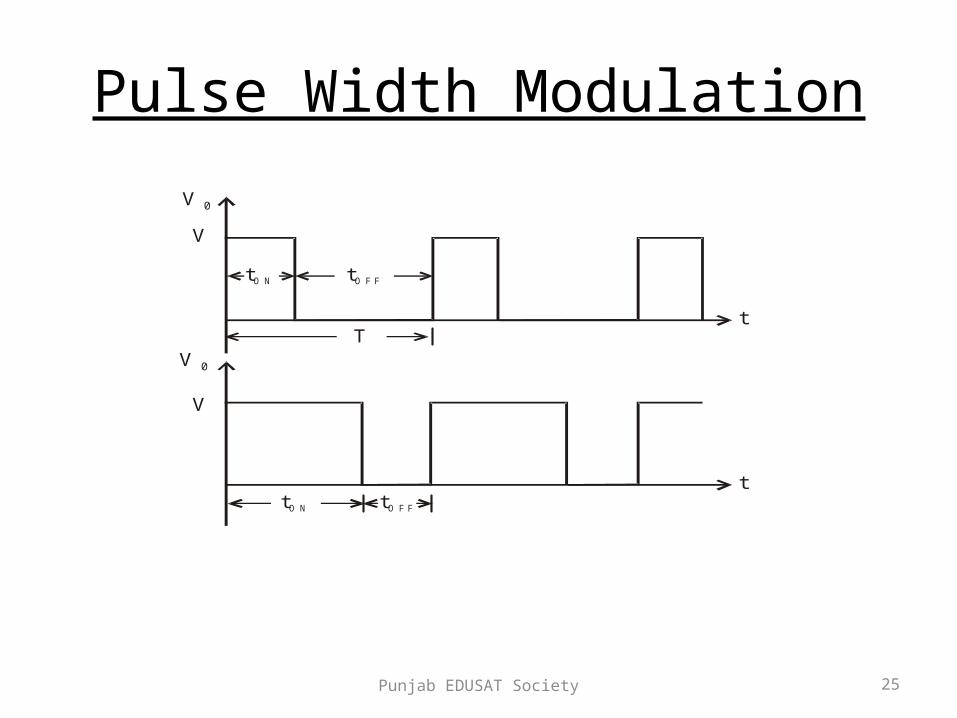
Pulse Width Modulation
• tON is varied keeping chopping frequency ‘f’ &
chopping period ‘T’ constant.
• Output voltage is varied by varying the ON
time tON
Punjab EDUSAT Society 25
Pulse Width Modulation
V 0
V
V
V 0
t
ttO N
tO N tO F F
tO F F
T

Punjab EDUSAT Society 26
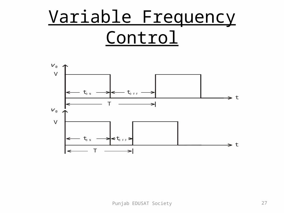
Variable Frequency Control
• Chopping frequency ‘f’ is varied keeping either tON or
tOFF constant.
• To obtain full output voltage range, frequency has to
be varied over a wide range.
• This method produces harmonics in the output and for
large tOFF load current may become discontinuous
Punjab EDUSAT Society 27
Variable Frequency Control
v 0
V
V
v 0
t
t
tO N
tO N
T
T
tO F F
tO F F

Punjab EDUSAT Society 28
Performance Parameters• The thyristor requires a certain minimum
time to turn ON and turn OFF. • Duty cycle d can be varied only between a
min. & max. value, limiting the min. and max. value of the output voltage.
• Ripple in the load current depends inversely on the chopping frequency, f.
• To reduce the load ripple current, frequency should be as high as possible.

Punjab EDUSAT Society 29
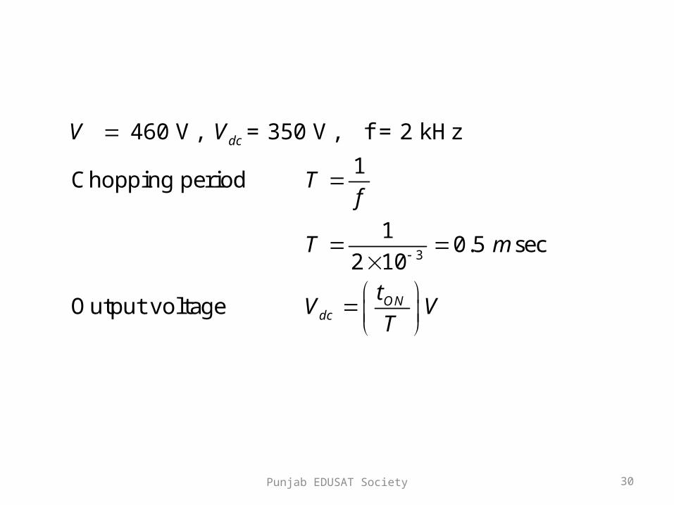
Example 1
• A Chopper circuit is operating on TRC at a frequency of 2 kHz on a 460 V supply. If the load voltage is 350 volts, calculate the conduction period of the thyristor in each cycle.
Punjab EDUSAT Society 30
3
460 V, = 350 V, f = 2 kHz
1Chopping period
10.5 sec
2 10
Output voltage
dc
ONdc
V V
Tf
T m
tV V
T
Punjab EDUSAT Society 31
3
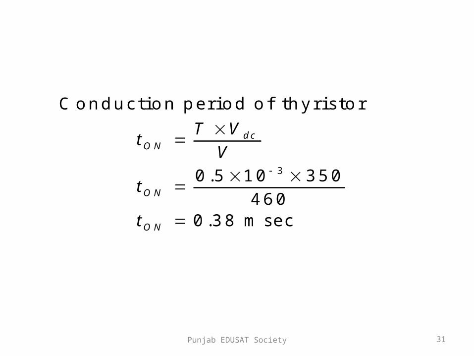
Conduction period of thyristor
0.5 10 350
4600.38 msec
dcON
ON
ON
T Vt
V
t
t
Punjab EDUSAT Society 32
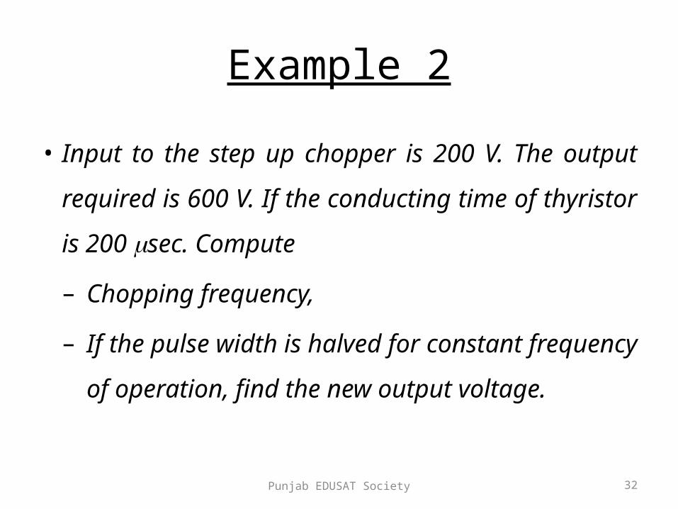
Example 2
• Input to the step up chopper is 200 V. The output
required is 600 V. If the conducting time of thyristor
is 200 sec. Compute
– Chopping frequency,
– If the pulse width is halved for constant frequency
of operation, find the new output voltage.
Punjab EDUSAT Society 33
6
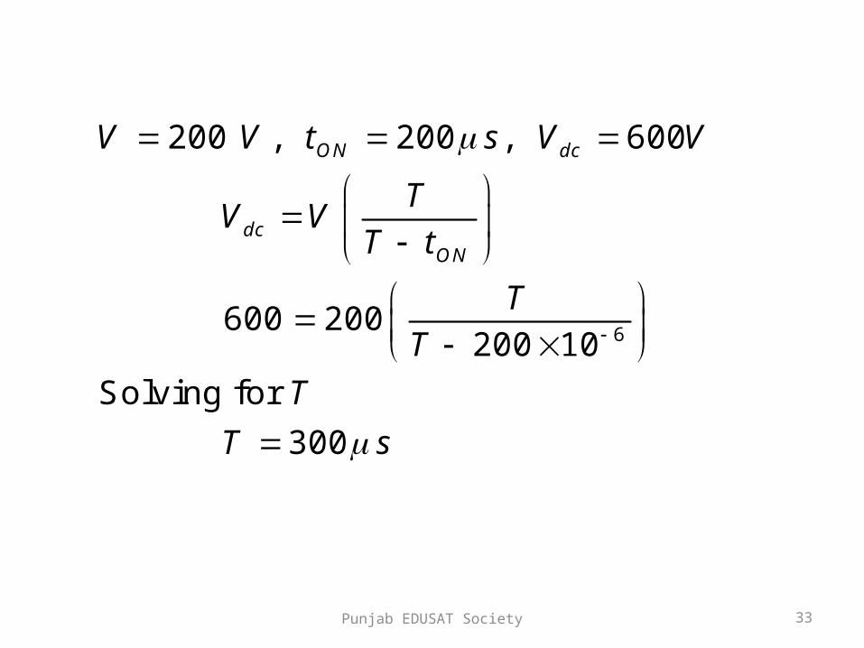
200 , 200 , 600
600 200200 10
Solving for
300
ON dc
dcON
V V t s V V
TV V
T t
T
T
T
T s

Punjab EDUSAT Society 34
6
6
Chopping frequency
1
13.33
300 10Pulse width is halved
200 10100
2ON
fT
f KHz
t s

Punjab EDUSAT Society 35
6
6
Frequency is constant
3.33
1300
Output voltage =
300 10200 300 Volts
300 100 10
ON
f KHz
T sf
TVT t
Punjab EDUSAT Society 36
Classification Of Choppers
• Choppers are classified as – Class A Chopper– Class B Chopper– Class C Chopper– Class D Chopper– Class E Chopper

Punjab EDUSAT Society 37
Class A Chopper
V
C hopper
FW D
+
v 0
v 0
i0
i0
LOAD
V

Punjab EDUSAT Society 38
• When chopper is ON, supply voltage V is connected
across the load.
• When chopper is OFF, vO = 0 and the load current
continues to flow in the same direction through the
FWD.
• The average values of output voltage and current
are always positive.
• Class A Chopper is a first quadrant chopper
Punjab EDUSAT Society 39
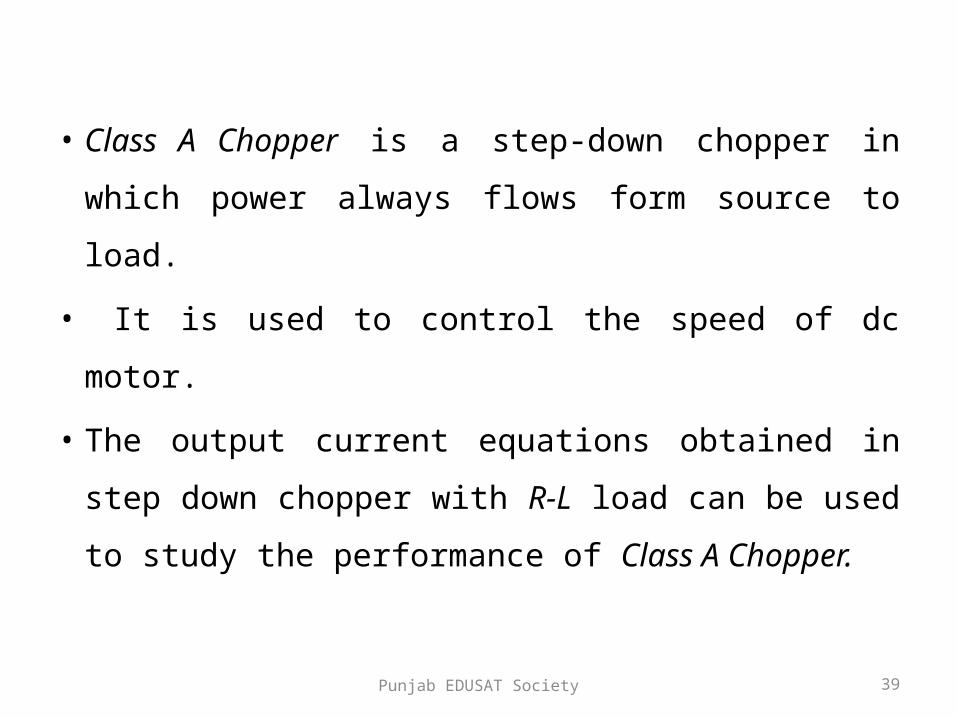
• Class A Chopper is a step-down chopper in
which power always flows form source to
load.
• It is used to control the speed of dc motor.
• The output current equations obtained in step
down chopper with R-L load can be used to
study the performance of Class A Chopper.

Punjab EDUSAT Society 40
O utpu t cu rren t
T hyristo rgate pu lse
O utpu t vo ltage
ig
i0
v 0
t
t
ttO N
T
C H O N
FW D C onduc ts
Punjab EDUSAT Society 41
Class B Chopper
V
C hopper
+
v 0
v 0
i0
i0
L
E
R
D

Punjab EDUSAT Society 42
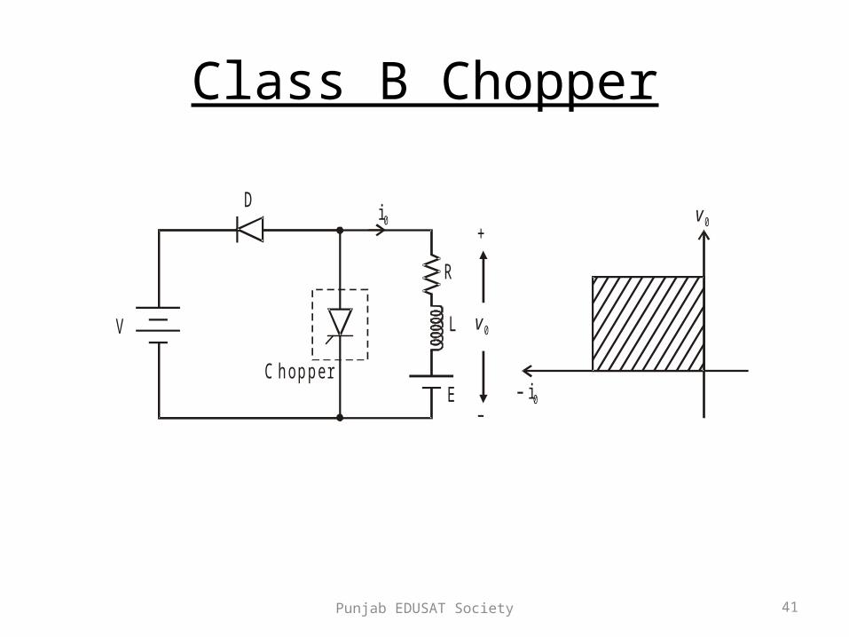
• When chopper is ON, E drives a current through
L and R in a direction opposite to that shown in
figure.
• During the ON period of the chopper, the
inductance L stores energy.
• When Chopper is OFF, diode D conducts, and part
of the energy stored in inductor L is returned to
the supply.
Punjab EDUSAT Society 43
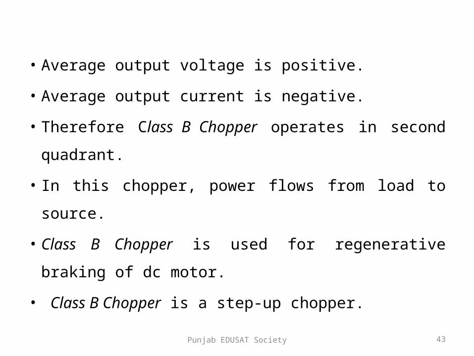
• Average output voltage is positive.
• Average output current is negative.
• Therefore Class B Chopper operates in second
quadrant.
• In this chopper, power flows from load to source.
• Class B Chopper is used for regenerative braking of dc
motor.
• Class B Chopper is a step-up chopper.
Punjab EDUSAT Society 44
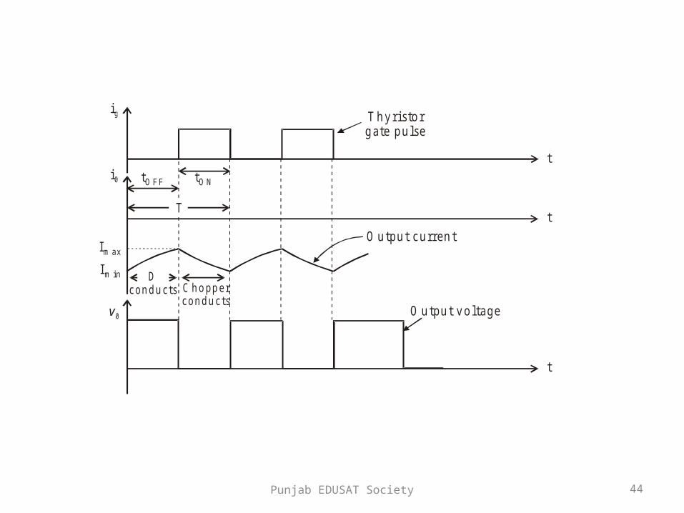
O utpu t cu rren t
D con d u cts C h o pp e r
con d u cts
T hyristo rgate pu lse
O utpu t vo ltage
ig
i0
v 0
t
t
t
Im in
Im ax
T
tO NtO F F

Punjab EDUSAT Society 45
Expression for Output Current
min
For the initial condition i.e.,
During the interval diode 'D' conduc
at 0
The solution of the ab
ts
voltage equation
ove equation is obtained
along similar lines as in s
is given by
OO
O
LdiV Ri E
dt
i t I t
tep-down chopper
with R-L load

Punjab EDUSAT Society 46
min
max
max min
During the interval chopper is ON voltage
equation is g
1 0
At
1
0
iven by
OFF OFF
R Rt tL L
O OFF
OFF O
R Rt tL L
OO
V Ei t e I e t t
R
t t i t I
V EI e I e
R
LdiRi E
dt
Punjab EDUSAT Society 47
max
max
min
min max
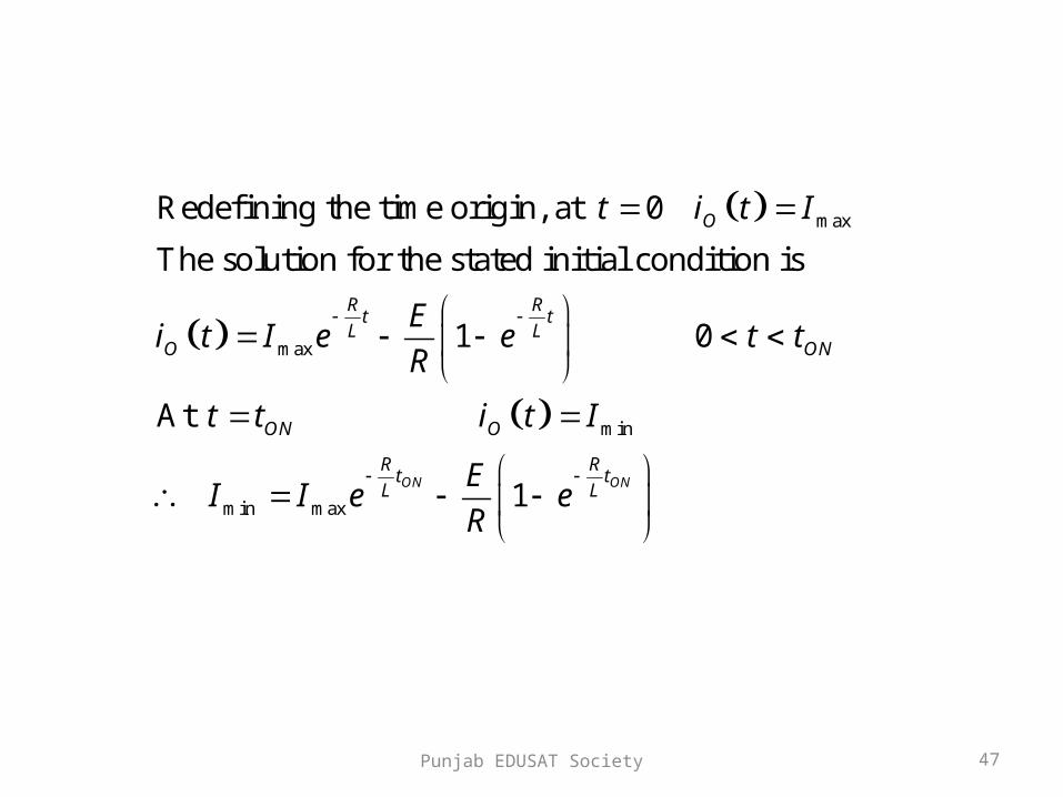
Redefining the time origin, at 0
The solution for the stated initial condition is
1 0
At
1ON ON
O
R Rt tL L
O ON
ON O
R Rt tL L
t i t I
Ei t I e e t t
R
t t i t I
EI I e e
R

Punjab EDUSAT Society 48
Class C Chopper
V
C hopper
+
v0
D 1
D 2C H 2
C H 1
v 0i0
i0
L
E
R

Punjab EDUSAT Society 49
• Class C Chopper is a combination of Class A and Class B Choppers.
• For first quadrant operation, CH1 is ON or D2 conducts.
• For second quadrant operation, CH2 is ON or D1 conducts.
• When CH1 is ON, the load current is positive.• The output voltage is equal to ‘V’ & the load
receives power from the source. • When CH1 is turned OFF, energy stored in
inductance L forces current to flow through the diode D2 and the output voltage is zero.
Punjab EDUSAT Society 50
• Current continues to flow in positive direction.• When CH2 is triggered, the voltage E forces
current to flow in opposite direction through L and CH2 .
• The output voltage is zero.• On turning OFF CH2 , the energy stored in the
inductance drives current through diode D1 and the supply
• Output voltage is V, the input current becomes negative and power flows from load to source

Punjab EDUSAT Society 51
• Average output voltage is positive• Average output current can take both positive
and negative values.• Choppers CH1 & CH2 should not be turned ON
simultaneously as it would result in short circuiting the supply.
• Class C Chopper can be used both for dc motor control and regenerative braking of dc motor.
• Class C Chopper can be used as a step-up or step-down chopper.

Punjab EDUSAT Society 52
G ate pu lseof C H 2
G ate pu lseof C H 1
O utput cu rren t
O utput vo ltage
ig 1
ig 2
i0
V 0
t
t
t
t
D 1 D 1D 2 D 2C H 1 C H 2 C H 1 C H 2
O N O N O N O N
Punjab EDUSAT Society 53
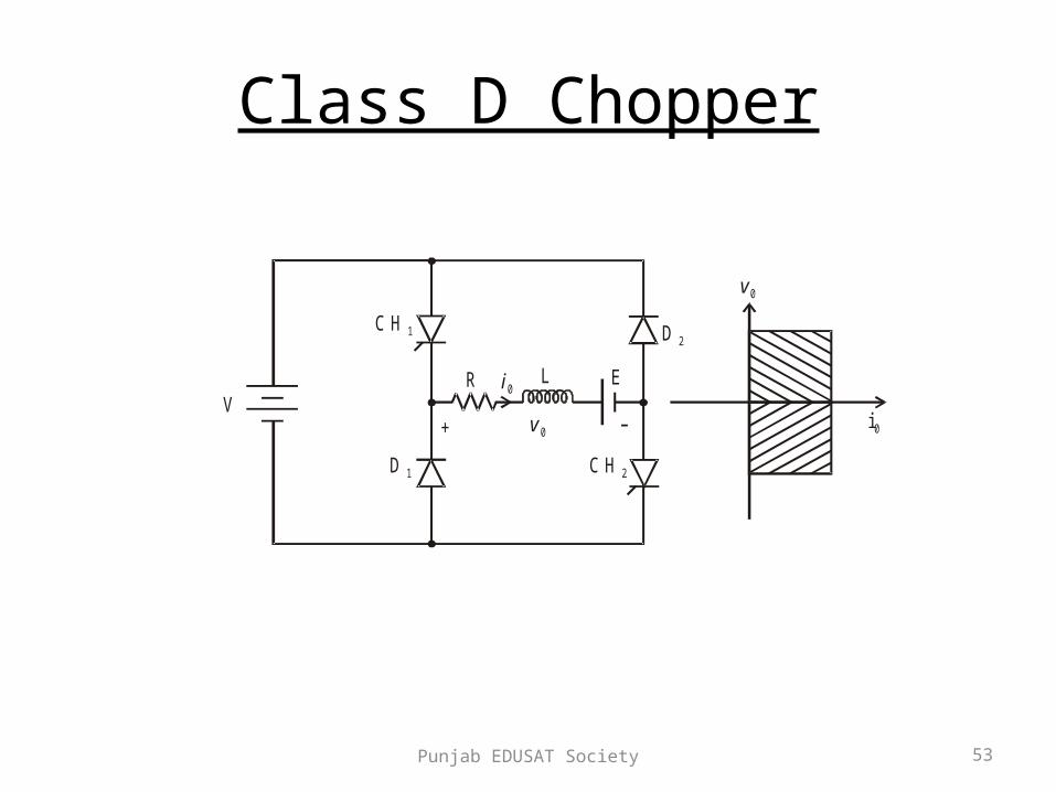
Class D Chopper
V+ v 0
D 2
D 1 C H 2
C H 1
v 0
i0
L ER i0
Punjab EDUSAT Society 54
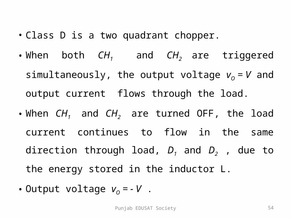
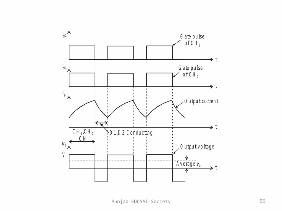
• Class D is a two quadrant chopper.
• When both CH1 and CH2 are triggered simultaneously,
the output voltage vO = V and output current flows
through the load.
• When CH1 and CH2 are turned OFF, the load current
continues to flow in the same direction through load,
D1 and D2 , due to the energy stored in the inductor L.
• Output voltage vO = - V .
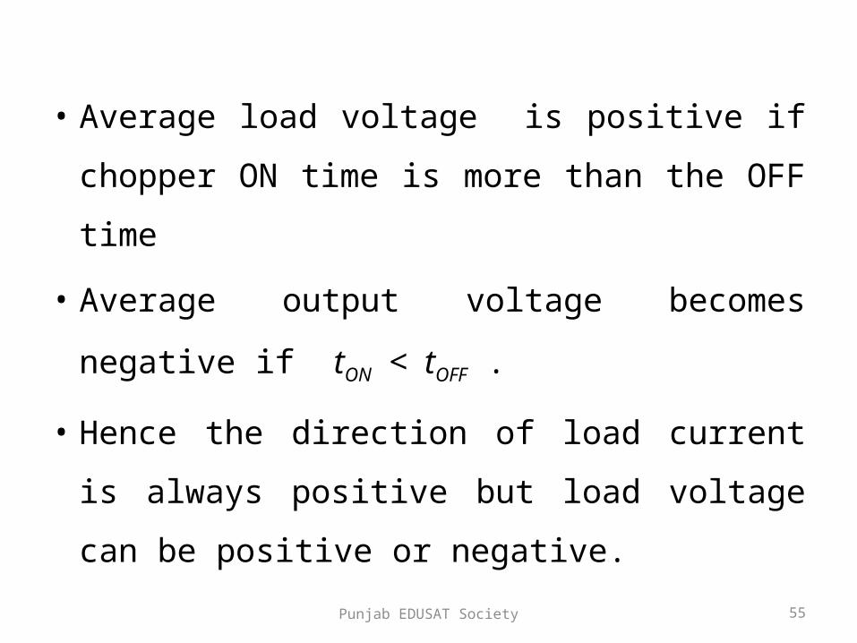
Punjab EDUSAT Society 55
• Average load voltage is positive if chopper ON
time is more than the OFF time
• Average output voltage becomes negative if
tON < tOFF .
• Hence the direction of load current is always
positive but load voltage can be positive or
negative.
Punjab EDUSAT Society 56
G ate pu lseof C H 2
G ate pu lseof C H 1
O utpu t curren t
O utpu t vo ltage
Average v0
ig 1
ig 2
i0
v 0
V
t
t
t
t
C H ,C HO N1 2 D 1,D 2 Conducting

Punjab EDUSAT Society 57
G ate pu lseo f C H 2
G ate pu lseo f C H 1
O utpu t curren t
O utpu t vo ltage
Average v 0
ig 1
ig 2
i0
v 0
V
t
t
t
t
C HC H
1
2
D , D1 2
Punjab EDUSAT Society 58
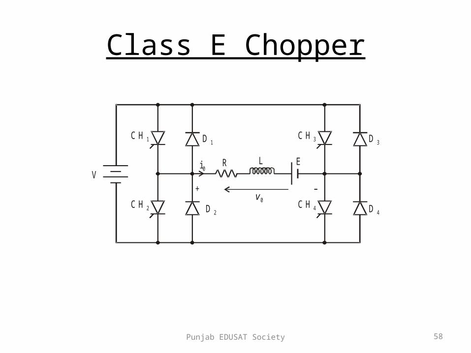
Class E Chopper
V
v 0
i0L ER
C H 2 C H 4D 2 D 4
D 1 D 3C H 1 C H 3
+
Punjab EDUSAT Society 59
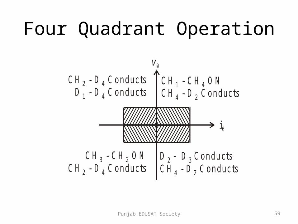
Four Quadrant Operation
v 0
i0
C H - C H O NC H - D C onducts
1 4
4 2
D D2 3 - C onductsC H - D C onducts4 2
C H - C H O NC H - D C onducts
3 2
2 4
C H - D C onductsD - D C onducts
2 4
1 4
Punjab EDUSAT Society 60
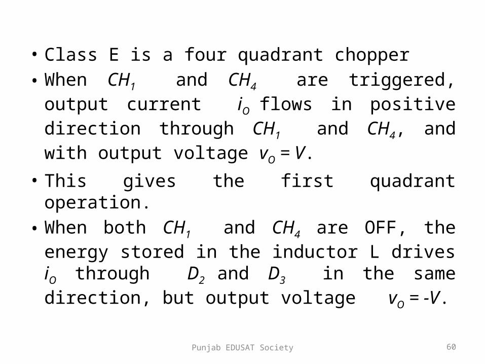
• Class E is a four quadrant chopper• When CH1 and CH4 are triggered, output
current iO flows in positive direction through CH1 and CH4, and with output voltage vO = V.
• This gives the first quadrant operation.• When both CH1 and CH4 are OFF, the energy
stored in the inductor L drives iO through D2 and D3 in the same direction, but output voltage vO = -V.
Punjab EDUSAT Society 61
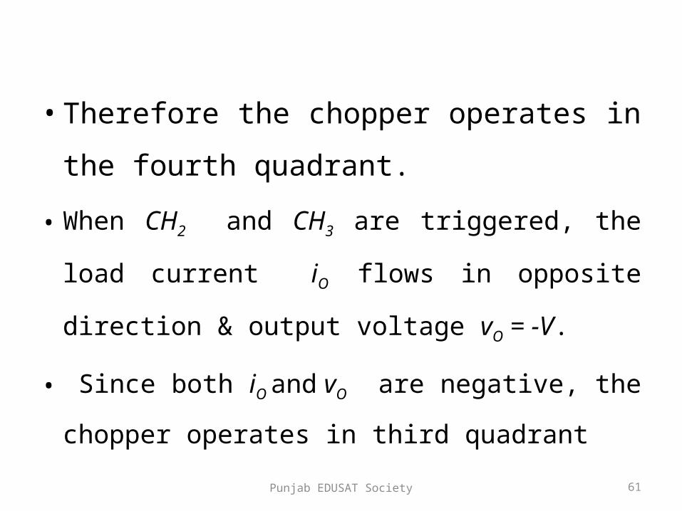
• Therefore the chopper operates in the fourth
quadrant.
• When CH2 and CH3 are triggered, the load current
iO flows in opposite direction & output voltage vO = -
V.
• Since both iO and vO are negative, the chopper
operates in third quadrant
Punjab EDUSAT Society 62
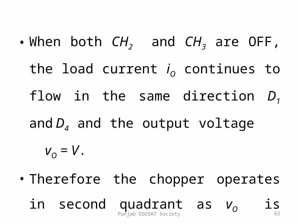
• When both CH2 and CH3 are OFF, the load
current iO continues to flow in the same
direction D1 and D4 and the output voltage
vO = V.
• Therefore the chopper operates in second
quadrant as vO is positive but iO is negative.
Punjab EDUSAT Society 63
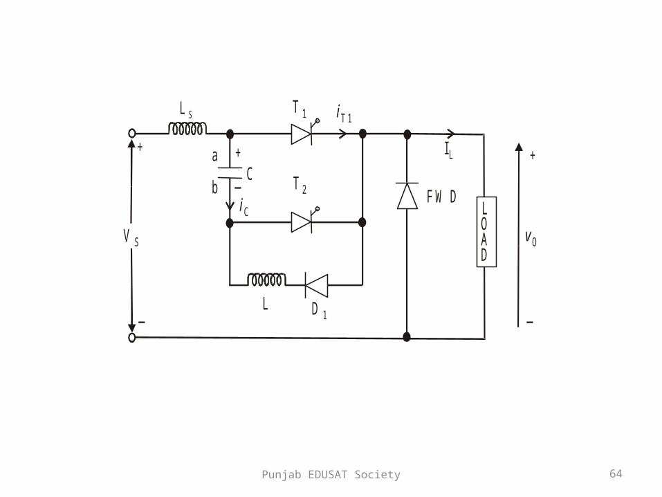
Voltage Commutated Chopper
• Voltage Commutated choppers are widely used in high power circuits where load fluctuation is not large.
• This chopper is also known as – Parallel capacitor turn-off chopper – Impulse Commutated chopper– Classical chopper.
Punjab EDUSAT Society 64
LOAD
L
C
IL
L S
V S
+
_
+
_
T 2
T 1
D 1
a
biC
iT 1
vO
+
_
FW D
Punjab EDUSAT Society 65
• To start the circuit, capacitor ‘C’ is initially charged with polarity (with plate ‘a’ positive) by triggering the thyristor T2.
• Capacitor ‘C’ gets charged through VS, C, T2 and load.
• As the charging current decays to zero thyristor T2 will be turned-off.
• With capacitor charged with plate ‘a’ positive the circuit is ready for operation.
• Assume that the load current remains constant during the commutation process

Punjab EDUSAT Society 66
• For convenience the chopper operation is divided into five modes:-– Mode-1– Mode-2– Mode-3– Mode-4– Mode-5

Punjab EDUSAT Society 67
Mode-1 Operation
LOADL
C
IL
L S
V S
+
_
+
_
T 1
D 1
V C iC
Punjab EDUSAT Society 68
• Thyristor T1 is fired at t = 0.
• The supply voltage comes across the load.
• Load current IL flows through T1 and load.
• At the same time capacitor discharges through T1,
D1, L1, & ‘C’ and the capacitor reverses its voltage.
• This reverse voltage on capacitor is held constant
by diode D1
Punjab EDUSAT Society 69
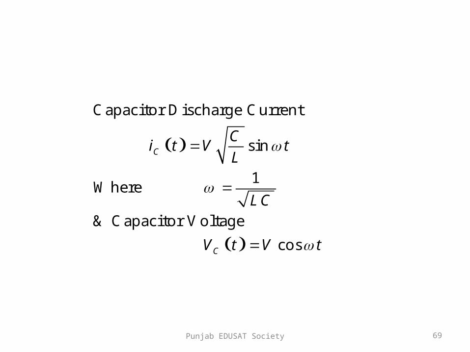
Capacitor Discharge Current
sin
1Where
& Capacitor Voltage
cos
C
C
Ci t V t
L
LC
V t V t

Punjab EDUSAT Society 70
Mode-2 Operation
LOAD
C
L S
V S+
_+
_
T 2
V C
IL
IL
Punjab EDUSAT Society 71
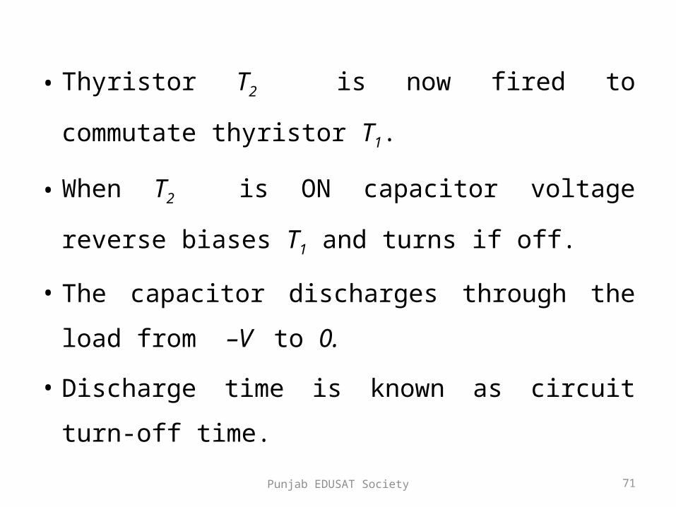
• Thyristor T2 is now fired to commutate thyristor T1.
• When T2 is ON capacitor voltage reverse biases T1
and turns if off.
• The capacitor discharges through the load from –V
to 0.
• Discharge time is known as circuit turn-off time.
Punjab EDUSAT Society 72
C
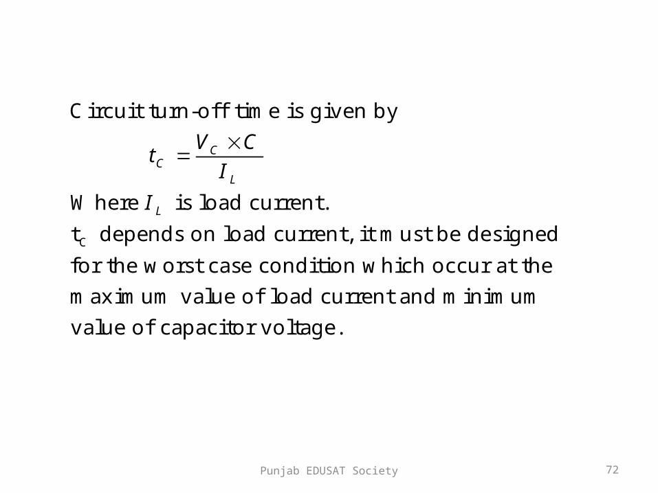
Circuit turn-off time is given by
Where is load current.
t depends on load current, it must be designed
for the worst case condition which occur at the
maximum value of load current and mini
CC
L
L
V Ct
I
I
mum
value of capacitor voltage.

Punjab EDUSAT Society 73
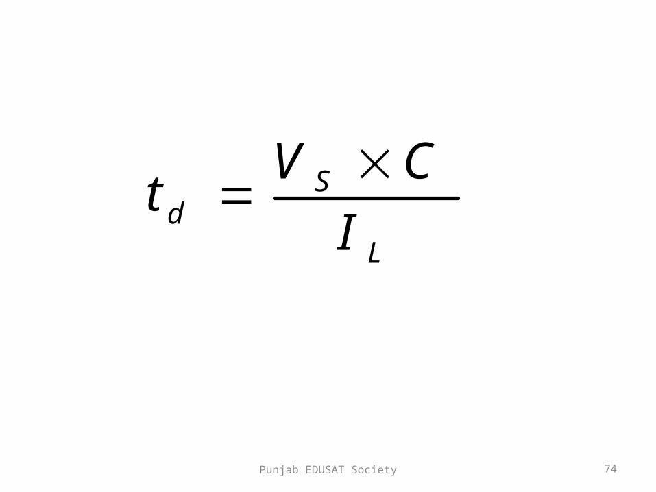
• Capacitor recharges back to the supply voltage (with plate ‘a’ positive).
• This time is called the recharging time and is given by:-
Punjab EDUSAT Society 74
Sd
L
V Ct
I

Punjab EDUSAT Society 75
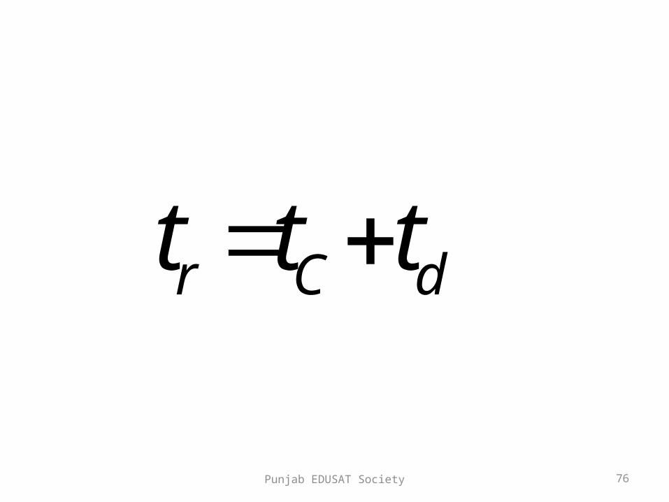
• The total time required for the capacitor to discharge and recharge is called the commutation time and it is given by:-
Punjab EDUSAT Society 76
r C dt t t
Punjab EDUSAT Society 77
• At the end of Mode-2 capacitor has recharged to VS and the free wheeling diode starts conducting

Punjab EDUSAT Society 78
Mode-3 Operation
LOAD
C
L S
V S
+_
+
_
T 2V S
FW D
IL
IL

Punjab EDUSAT Society 79
• FWD starts conducting and the load current
decays.
• The energy stored in source inductance LS is
transferred to capacitor.
• Hence capacitor charges to a voltage higher
than supply voltage, T2 naturally turns off.
Punjab EDUSAT Society 80
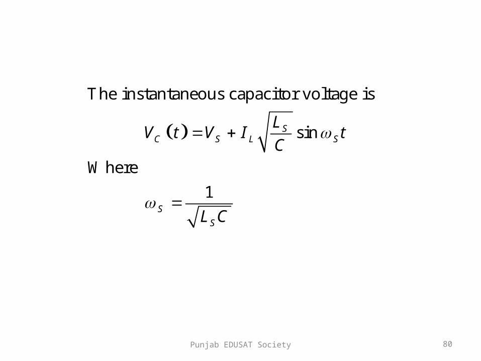
The instantaneous capacitor voltage is
sin
Where
1
SC S L S
S
S
LV t V I t
C
L C

Punjab EDUSAT Society 81
Mode-4 Operation
LOAD
C
L S
V S
+_
+
_
D 1
LFW D
IL
V C
Punjab EDUSAT Society 82
• Capacitor has been overcharged i.e. its voltage is above supply voltage.
• Capacitor starts discharging in reverse direction.
• Hence capacitor current becomes negative. • The capacitor discharges through LS, VS, FWD,
D1 and L. • When this current reduces to zero D1 will stop
conducting and the capacitor voltage will be same as the supply voltage

Punjab EDUSAT Society 83
Mode-5 Operation
LOAD
IL
FW D
Punjab EDUSAT Society 84
• Both thyristors are off and the load current
flows through the FWD.
• This mode will end once thyristor T1 is fired

Punjab EDUSAT Society 85
C a p a c i t o r C u rr e n tI L
t
t
I p C u r r e n t t h r o u g h T 1
ic
0Ip
iT1
0
I L

Punjab EDUSAT Society 86
t
t
t
Vo l ta g e a c r o s s T 1
O u tp u t Vo l t a g e
C a p a c i t o r Vo l t a g e
tctd
v T1
V c
0v o
V s c+ V
V s
v c
V c
-V c

Punjab EDUSAT Society 87
Disadvantages
• A starting circuit is required and the starting circuit should be such that it triggers thyristor T2 first.
• Load voltage jumps to almost twice the supply voltage when the commutation is initiated.
• The discharging and charging time of commutation capacitor are dependent on the load current and this limits high frequency operation, especially at low load current

Punjab EDUSAT Society 88
• Chopper cannot be tested without connecting
load.
• Thyristor T1 has to carry load current as well
as resonant current resulting in increasing its
peak current rating.

Punjab EDUSAT Society 89
THANKS