topical aspects on monitoring airborne radioactive effluents from npps wan-tae kim
TRANSCRIPT

Topical Aspects on Monitoring Airborne Radioactive Effluents from NPPs
Wan-tae KIM

Contents
• Concepts of Monitoring
• Guidelines of Monitoring
• Status of Monitoring

I. Concepts of Monitoring
MONITORING
WHATWHAT
WHENWHENWHYWHY
HOWHOW WHEREWHERE

Monitoring What
• All radioactive effluents to the environment
• Two broad source types at NPPs• Point source : stacks and ducts• Nonpoint source : all other sources
• Focus on aerosol effluents from point source

Monitoring Why
• For evaluation• the environmental impact• the potential annual radiation doses to the public• adequacy and performance of containment, waste
treatment methods, and effluent controls
• To ascertain• regulatory requirements and LCO have been met• concentrations have been kept ALARA

Monitoring When
• Continuously or periodically
• At all conditions of reactor operation• Normal• Off-normal
• Anticipated operational occurrences
• Post-accident
• Off-normal case should consider leakage of particles through filter media, filter seals, and cracks in filter frames

Monitoring Where (1)
• All major and potentially significant paths
• In 40 CFR Part 61.93 (4)(i) : continuous monitor at release points that have the potential effective dose equivalent (EDE) ≥ 0.1 mrem/yr
• NUREG-0800, SRP 11.5, table 1 lists all paths

Monitoring Where (2)
NUREG-0800
11.5
Table 1
Monitoring How
• Combination of direct measurement, sample extraction, and analysis
• Sample extraction is performed with sampling system
• Sampling system is very useful, but there are a lot of complexities for getting representative samples
Sampling System
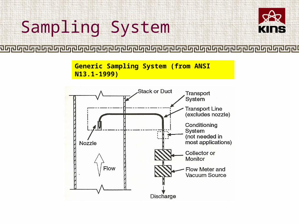
Generic Sampling System (from ANSI N13.1-1999)

Continuous Air Monitor
P&ID of a CAM Sampler

II. Guidelines of Monitoring
ANSI N13.1-1969
ANSI N13.1-1999
1981 NRC : SRP 11.5 ver.3 - ANSI N13.1(1969)
1989 NRC : petition for regulation duplicate
1997 KINS : SRP 11.5 ver.0 - ANSI N13.1(1969)
2000 DOE : present DOE Position to EPA - No supporting complete retrofitting &replacementof all existing monitoring devices
2007 NRC : SRP 11.5 ver.4 - ANSI N13.1(1999)
1996 NRC : announce new Constraint Rule - transfer 0.1 mSv/yr to 10 CFR 20
1996 NRC : SRP11.5 Draft ver.4-ANSI N13.1(1993)
1990 DOE : follow Rad NESHAP-ANSI N13.1(1969)
1977 CAAA : EPA limit emission to air1983 EPA : propose NESHAP – DOE &NRC1987EPA:Case of VCD-reconsider NESHAP
1993, proposeANSI N13.1-199X
1989 EPA:promulgate-40 CFR 61, Subpart I & HDecision-making : VCD & benzene policy
No member of public exceeds 0.1 mSv/yr
1990 EPA: publish Rad NESHAP - 0.1 mSv/yrEPA(1993a) : ANSI N13.1-1969
EPA(1993b) : “8-2 rule” or “duct diameter”
1997 EPA : rescind - 40 CFR 61, Subpart I
2002 EPA : update - Rad NESHAP ANSI N13.1-1999 use for new & modifiedImpose additional inspection on existing

Rad NESHAP (40 CFR 61, Subpart H)
• Rad NESHAP standard for public dose limit• from 1 mSv/yr to 0.1 mSv /yr• from all pathway to just only air pathway
• The technical requirements for determining dose to the public became more rigidly defined
• So, called out the ANSI N13.1-1969 as in USEPA(1993a)
• In addition, sampling sites are required to be selected following procedures in USEPA(1993b)

Deficiency in USEPA(1993b)
• USEPA(1993b) require that sampling should be done at least 5 - 8 diameters downstream from a disturbance and at least 2 diameters upstream flow disturbances
• Techniques is clear, but no criteria
• Assumption : the degree of flow development and mixing are directly related to the distance from disturbance
• This, unfortunately, is not necessarily true

Deficiency in USEPA(1993a) - 1
• USEPA(1993a) assumes nothing about flow development and mixing and calls out ANSI recommendations for probe design
• However, other characteristics of the bulk effluent (i.e., the degree of flow development and particulate mixing) are also critical to determine the design requirements of the probe
• ANSI N13.1(1969) provides guidance for particulate sampling probes that utilize a multinozzle array to accomodate any deficiencies in the flow development or mixing
Deficiency in USEPA(1993a) – 2
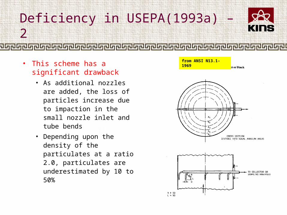
• This scheme has a significant drawback• As additional nozzles are
added, the loss of particles increase due to impaction in the small nozzle inlet and tube bends
• Depending upon the density of the particulates at a ratio 2.0, particulates are underestimated by 10 to 50%
from ANSI N13.1-1969

ANSI N13.1-1999
• ANSI N13.1-1999 compensate the deficiencies in USEPA(1993a) and USEPA(1993b)
• ANSI N13.1-1999 is a performance-based standard rather than the prescriptive 1969 version
• To assure a representative sample is collected, the standard established required sampling system performance criteria

Performance Criteria (1)
• Total transport of 10 μm AD particles and vaporous contaminants shall be 〉 50% from the free stream to the collector/analyzer
• Sampler nozzle inlet shall have a transmission ratio between 80% and 130% for 10 μm AD particles
• Sampler nozzle shall have an aspiration ratio that does not exceed 150% for 10 μm AD particles

Performance Criteria (2)
• Characteristics of a suitable sampling location are :• coefficients of variation over the central 2/3 area of the cros
s section within ±20% for 10 μm AD particles, gaseous tracer, and gas velocity
• flow angle 〈 20° relative to the long axis of the stack and nozzle inlet
• the tracer gas concentration shall not vary from the mean 〉30% at any point on a 40 CFR 60, Appendix A, Method 1 velocity mapping grid

Performance Criteria (3)
• Effluent flowrate continuous measurement required if flow variation is 〉 ± 20% in a year
• Effluent and sample flow rate shall be measured within ±10%
• Continuous sample flowrate measurement and control required if flow varies 〉 ±20% during a sample interval• flow control shall be within ±15%

III. Status of Monitoring
0
2
4
6
8
10
12
PHWR PWR- WH PWR- CE PRAMATOM OPR- 1000 OPR- 1400
222200
• 20 units under operation• 6 units under construction• All NPPs under operation use stacks (and ducts) sampling system
with isokinetic multiple small-diameter nozzles• Besides, the APR-1000 and APR-1400 have much more number of
stacks and ducts
Design Differences
• Status of sampling system at 4 units has been surveyed during regular inspection in 2007
• Considerable matters are listed :• the ratio of effluent/sample flow rate ranges from
10000 to 100000 • unbalance seems to exist among the components• transport line seems too long, lots of bends• information related sampling location, nozzle, and
transport line for old system is absent• no total procedures to maintain sampling system• no method to inspect the inner sampling site

Data Comparability
• Uniform method can provide a uniform basis for data comparison from the different facilities
• Uniform method can be maintained with• Periodic inspections of nozzle, transport lines, sample and ef
fluent flowmeters shall be conducted• Periodic calibrations of effluent and sample flowmeters, CAM
s, and sample analysis instrumentation shall be conducted

Under Tasks
• New plants under construction in Korea are planning to use ANSI N13.1-1999
• The performance criteria of ANSI N13.1-1999 have been studied to impose on the existing facilities