topical review open access 7kh «vnlqhiihfw ¬
TRANSCRIPT
International Journal of Extreme Manufacturing
TOPICAL REVIEW • OPEN ACCESS
The ‘skin effect’ of subsurface damage distribution in materials subjectedto high-speed machiningTo cite this article: Bi Zhang and Jingfei Yin 2019 Int. J. Extrem. Manuf. 1 012007
View the article online for updates and enhancements.
This content was downloaded from IP address 101.206.226.222 on 07/05/2019 at 04:59

Topical Review
The ‘skin effect’ of subsurface damagedistribution in materials subjected tohigh-speed machining
Bi Zhang1,2 and Jingfei Yin3
1 The Southern University of Science and Technology, Shenzhen, People’s Republic of China2 The University of Connecticut, Storrs, CT, United States of America3Dalian University of Technology, Dalian, People’s Republic of China
E-mail: [email protected], [email protected] and [email protected]
Received 15 March 2019Accepted for publication 15 March 2019Published 16 April 2019
AbstractThis paper proposes the ‘skin effect’ of the machining-induced damage at high strain rates. Thepaper first reviews the published research work on machining-induced damage and thenidentifies the governing factors that dominate damage formation mechanisms. Among manyinfluential factors, such as stress–strain field, temperature field, material responses to loading andloading rate, and crack initiation and propagation, strain rate is recognized as a dominant factorthat can directly lead to the ‘skin effect’ of material damage in a loading process. The paperelucidates that material deformation at high strain rates (>103 s−1) leads to the embrittlement,which in turn contributes to the ‘skin effect’ of subsurface damage. The paper discusses the ‘skineffect’ based on the principles of dislocation kinetics and crack initiation and propagation. Itprovides guidance to predicting the material deformation and damage at a high strain-rate forapplications ranging from the armor protection, quarrying, petroleum drilling, and high-speedmachining of engineering materials (e.g. ceramics and SiC reinforced aluminum alloys).
Keywords: skin effect, strain rate, dislocation, embrittlement, damage
(Some figures may appear in colour only in the online journal)
1. Introduction
The term ‘skin effect’ has been used to describe distributionof the alternating current in a conductor that electric currentmainly flows in the ‘skin’ layer of the conductor. The currentdensity is the highest at the surface layer of the conductor andquickly decreases in the inner layers. The ‘skin effect’ isfurther strengthened at a higher frequency of the alternatingcurrent. Similarly, the authors have found that the ‘skin effect’of subsurface damage (SSD) distribution also exists in
material deformations. The ‘skin effect’ of SSD distributioncan be enhanced at a higher strain rate in a loading process.
Generally, an increased strain-rate results in embrittlementof the material subjected to loading, which in turn leads to the‘skin effect’. For example, in armor applications, the brittle-ness of the material greatly affects the ballistic performance ofan armor. Ceramics generally have better resistance to theballistic impact than metallic materials [1, 2]. Another exampleis the high-speed machining (HSM) of engineering materials,such as ceramics and SiC reinforced aluminum alloys. Highspeeds of machining could embrittle the workpiece materialand suppress SSD depth because of the ‘skin effect’.
We are living in a world that needs support from variousmaterials. How these materials may serve our purposes hasbeen a subject of study. Some materials are harder and more
| IMMT International Journal of Extreme Manufacturing
Int. J. Extrem. Manuf. 1 (2019) 012007 (12pp) https://doi.org/10.1088/2631-7990/ab103b
Original content from this work may be used under the termsof the Creative Commons Attribution 3.0 licence. Any
further distribution of this work must maintain attribution to the author(s) andthe title of the work, journal citation and DOI.
© 2019 The Author(s). Published by IOP Publishing Ltd on behalf of the IMMT2631-8644/19/012007+12$33.00 1

brittle (e.g. ceramics, semiconductors, cast irons) than others(e.g. most metals). It is necessary to shape the materials intovarious products with the help of modern manufacturingtechnologies, such as machining, laser beam cutting, forming,forging and welding. On the other hand, we want the productsto perform the functions as we desire. These functions mayinclude strength and toughness, fatigue strength (e.g. aircraftengines and bridges), wear resistance (e.g. bearings and cut-ting tools), etc. To achieve the respective functions, the rightmaterials must be chosen for the appropriate applications.Titanium, Inconel, and aluminum alloys, for example, arenormally used in the aerospace applications [3, 4]. Crystallinesilicon is a typical substrate material for the semiconductor[5–7] and photovoltaic industries [8, 9]. Sapphire is used asthe substrate material for LEDs [10–12]. Ceramics have beenused in the high-precision bearings and cutting tools [13, 14].Glasses are indispensable materials for optics and lighttransmission [15]. However, the above-mentioned materialscan easily be induced with SSD when they are subjected tomachining.
In machining of titanium, Inconel and aluminum alloys,work hardening and tool wear are notable, resulting in ametamorphic layer on the machined surface [16–19]. Generally,the metamorphic layer degrades the service performance of apart because of the different mechanical properties from thebulk material, such as hardness, toughness, and plasticity[20, 21]. On the other hand, materials, such as SiC, sapphire,and silicon, are hard and brittle, and can easily be introducedwith SSD during a machining process [7, 15, 22], which isdetrimental to the performance and lifetime of a part.
As shown in figure 1, an as-received cutting tool insertoffered a lifetime of approximately 49 min. However, whenanother insert of the same batch from the same manufacturerwas finished by the magnetic abrasive finishing (MAF)technique, its lifetime was 86 min, almost doubling the life-time of the as-received version. Why should this happen?What is the function of MAF on the lifetime of the insert?
To answer these questions, an early work conducted byZhang et al [24, 25] should be referred to. In their work, Zhanget al produced a smooth groove in a hot-pressed alumina samplein the single-point grinding process at a speed of 1800mmin−1.Figure 2 shows the images of the groove taken from the top andcross-sectional views by a scanning electron microscope (SEM).Figure 2(a) presents the top view of the groove with a smoothsurface. Although the groove did not show any observabledamage (e.g. cracking, chipping), its subsurface was severelydamaged with a layer of pulverization, as shown in figure 2(b).Moreover, the cross-sectional view reveals that material pile-upoccurred to the two sides of the groove. The pile-up was clearlybecause of the side flow of the pulverized material. Therefore,pile-up does not have to be plastic deformation in the machiningof the hard and brittle materials.
Based on the understanding of figure 2, it is suggestedthat the cutting edge of the as-received insert in figure 1should have been left with the grinding-induced SSD which isresponsible for the compromised tool life. Upon the removalof SSD by the MAF technique, tool life was largely extended,as depicted in figure 1. Therefore, the removal of themachining-induced damage is beneficial to the improvementof the performance and lifetime of a cutting tool.
Over the years, continuous efforts have been made inmachining of hard and brittle materials. Bifano et al [26] were
Figure 1. Maximum flank wear of the different tool inserts versusmachining time (cutting speed: 100 m min−1, feed: 75 μm/rev,depth of cut: 1.0 mm, coolant: 5% vol. trim solution). Reprintedfrom [23], Copyright (2012), with permission from Elsevier.
Figure 2. SEM images of (a) top view and (b) cross-sectional view ofa smooth groove generated by grinding in an alumina sample. [24](1988) © Chapman and Hall Ltd. With permission of Springer.
2
Int. J. Extrem. Manuf. 1 (2019) 012007 Topical Review

the first to propose the ‘ductile-regime’ machining techniquefor brittle materials to achieve high-quality grinding.Although ‘ductile-regime’ machining has received muchattention, it is still controversial as it lacks both theoreticaland experimental support. This technique is mainly concernedwith surface finish with no consideration of SSD of amachined workpiece. It has not solved the machining pro-blems of the hard and brittle materials.
In order to solve these problems, Zhang et al [25] used adifferent approach. They not only investigated the surface butalso the subsurface characteristics of a machined workpiece.They were the first to report the material pulverizationmechanism together with the other forms of machining-induced SSD in ceramics [24, 25, 27–30]. Their findings havebeen applied in industry for high efficiency and low damagemachining of ceramic materials.
Ultrasonically-assisted machining (UAM) has success-fully been used in reducing machining force and improvingsurface integrity for the hard and brittle materials [31–35]. Infact, UAM helps suppress machining-induced damage,enhance the critical depth of cut [31], reduce machiningforces [32, 36], and alter material properties [37]. UAM has agreat potential for machining of the hard and brittle materials,however, there are still critical issues to be resolved. Theissues include how UAM suppresses the machining-induceddamage and improves workpiece surface integrity.
HSM has attracted much attention because of itsimprovement in machining efficiency, reduction in tool wear,and suppression in workpiece damage as compared to theconventional machining [38–40]. HSM can be applied tomany different materials with no specific requirements on theworkpiece properties. Most of all, HSM leads to a high strainrate which results in the so-called ‘skin effect’, namely, themachining-induced SSD tends to distribute in the superficiallayer of a workpiece machined at a high strain rate [41–45].Therefore, HSM presents a huge potential in high-efficiencymachining of the above-mentioned materials. However, theunderlying mechanisms of the ‘skin effect’ of SSD distribu-tion remain unrevealed and need investigations.
This paper is to explore the mechanisms of the ‘skineffect’ of SSD at high strain rates and its application to HSM.Among the differences between HSM and the low-speedmachining, the strain rate is the primary factor. This paperpresents the ‘skin effect’ of SSD distribution at high strainrates (>103 s−1) with section 2 dealing with the ‘skin effect’of machining-induced damage. Section 3 discusses theunderlying mechanisms of the ‘skin effect’ at high strainrates; section 4 discusses the ‘skin effect’ in terms of dis-location and energy theories; section 5 concludes the paperand presents an outlook.
2. ‘Skin-effect’ of damage at high strain rates
In machining, the plastic strain rate dε/dt is regarded as afunction of rake angle γ of a cutting tool, shear angle j,cutting speed V, and the elemental chip thickness Δy, as
presented in equation (1) [46, 47],
d
dt
V
y
cos
cos, 1
e gj g
=D -( )
( )
where the elemental chip thickness is related to the depth ofcut. However, equation (1) cannot be used to calculate thestrain rate in the machining of hard and brittle materialsbecause these materials do not normally show notable plasticdeformation before fracturing. Wang et al proposed a simpleformula for calculating strain rate, shown as equation (2) [48],
d
dt
V
a, 2
c
e= ( )
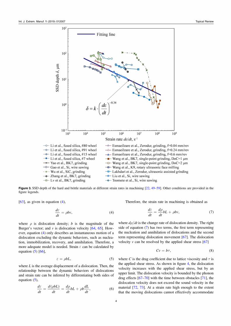
where ac represents depth of cut. Equation (2) describes strainrate in the region of a material compressed by a cutting tool.In this study, equation (2) is adopted to calculate strain ratebased on the previous studies. As shown in figure 3, the SSDdepth in the hard and brittle materials decreases with anincrease in strain rate of machining, which well depicts the‘skin effect’ of damage formation in terms of strain rate. Thebest fitting line in figure 3 shows that the SSD depth ismathematically proportional to the negative exponent ofstrain rate, as presented in equation (3),
kd
dt, 3
0.34
de
=-
⎜ ⎟⎛⎝
⎞⎠· ( )
where k is a constant (k=1531 in figure 3).In addition, the ‘skin effect’ can also be found in the
metallic materials. The ‘skin effect’ was identified in theearly works conducted on IN-718 by Pawade et al [60], onthe nickel-based FGH95 superalloys by Jin et al [42, 43], onthe D2 tool steels by Kishawy and Elbestawi [61], and on thenickel-based ME16 superalloys by Veldhuis et al [62].Therefore, the ‘skin effect’ exists not only in the hard andbrittle materials, such as ceramics, semiconductor materials,and glasses, but also in the metallic materials, such assuperalloys and tool steels.
The ‘skin effect’ is an intrinsic property that governs thedamage behavior of the engineering materials. The ‘skineffect’ can be interpreted as ‘material damage (e.g. cracking,dislocation, phase transformation) is localized if the materialis loaded at a high strain rate’. In the case of machining, forexample, SSD depth decreases at an increased machiningspeed (strain rate), and vice versa.
3. Mechanisms of the ‘skin-effect’ of damage at highstrain rates
3.1. Material embrittlement
Generally, a material subjected to machining undergoesplastic deformation before it fractures. The plastic deforma-tion is governed by dislocation motion which is dependent onstrain and strain rate. The relationship between the dislocationmotion and strain rate is inferred based on the Orowan theory
3
Int. J. Extrem. Manuf. 1 (2019) 012007 Topical Review
[63], as given in equation (4),
d
dtbv, 4
er= ( )
where ρ is dislocation density; b is the magnitude of theBurger’s vector; and v is dislocation velocity [64, 65]. How-ever, equation (4) only describes an instantaneous motion of adislocation excluding the dynamic behaviors, such as nuclea-tion, immobilization, recovery, and annihilation. Therefore, amore adequate model is needed. Strain e can be calculated byequation (5) [66],
bL, 5e r= ( )
where L is the average displacement of a dislocation. Then, therelationship between the dynamic behaviors of dislocationsand strain rate can be inferred by differentiating both sides ofequation (5),
d
dt
d bL
dt
d
dtbL b
dL
dt, 6
e r rr= = +
( ) ( )
Therefore, the strain rate in machining is obtained as
d
dt
d
dtbL bv, 7
e rr= + ( )
where dρ/dt is the change rate of dislocation density. The rightside of equation (7) has two terms, the first term representingthe nucleation and annihilation of dislocations and the secondterm representing dislocation movement [67]. The dislocationvelocity v can be resolved by the applied shear stress [67]
Cv b , 8t= ( )
where C is the drag coefficient due to lattice viscosity and τ isthe applied shear stress. As shown in figure 4, the dislocationvelocity increases with the applied shear stress, but by anupper limit. The dislocation velocity is bounded by the phonondrag effects [67–70] with the time between obstacles [71], thedislocation velocity does not exceed the sound velocity in thematerial [72, 73]. At a strain rate high enough to the extentthat the moving dislocations cannot effectively accommodate
Figure 3. SSD depth of the hard and brittle materials at different strain rates in machining [22, 49–59]. Other conditions are provided in thefigure legends.
4
Int. J. Extrem. Manuf. 1 (2019) 012007 Topical Review

loading, more dislocations nucleate, emitting at the soundvelocity, and resulting in a dislocation avalanche.
Dislocations can be classified into two types, mobile andimmobile. The mobile dislocations may be trapped by eachother and turned into immobile ones because of their inter-actions, including entanglement, attraction, obstruction, etc.Therefore, material deformation enhances not only disloca-tion nucleation and motion, but also dislocation immobiliza-tion. The accumulation of the immobile dislocations increasesthe resistance to plastic deformation and leads to materialhardening [75]. At a high strain rate, dislocation avalanchemay dramatically increase the density of the immobile dis-locations which are responsible for material hardening.Consequently, the plastic deformation of a material is sup-pressed before fracturing, namely, the material is embrittled.
In terms of the strength enhancement, both tensilestrength σb and yield strength σs increase with strain rate, asshown in figure 5. However, as strain rate increases, the yieldstress increases more rapidly than the tensile strength and the
yield-to-tensile ratio σs/σb increases. At a high strain rate(> 104 s−1), the yield strength approaches the tensile strength.As a limit, the yield strength can be the same as but neversurpass the tensile strength [76]. In this case, the materialfractures prior to yielding, which is a typical characteristic ofa brittle material. Material embrittlement due to the strain rateeffect is thus realized.
As shown in equation (2), strain rate is determined basedon cutting speed and depth of cut in the case of machining.Therefore, the strain-rate evoked embrittlement can be acquiredby increasing cutting speed and decreasing depth of cut. Asshown in figure 6 (a), at a cutting speed of 1000mmin−1, thecutting chip exhibited a typical continuous morphology for aductile material, such as an aluminum alloy. However, as thecutting speed increased to 5000mmin−1, the chip morphologyturned to be fragmental, as shown in figure 6(b), which meansthat the material has been embrittled under this condition.
For brittle materials, Lawn and Marshall first proposedthat the ratio of hardness to fracture toughness should be usedto estimate the brittleness of a material [80]. Boccaccini stu-died the machinability of a glass-ceramics in terms of thematerial brittleness represented in equation (9)
BH
K, 9
C= ( )
where H and Kc are the hardness and fracture toughness of thematerial, respectively.
It should be pointed out that material hardness H isstrain-rate sensitive and generally increases with strain rate[16, 45, 81–85] due to the strain-rate hardening effect. Acorrelation between hardness and strain rate is expressed inequation (10) [86]
Hd
dt, 10
meµ ⎜ ⎟⎛
⎝⎞⎠ ( )
where m represents strain-rate exponent, and m=0 for arigid-perfectly plastic material and m=1 for a linear viscoussolid, respectively [87, 88]. Hardness has a power lawdependence on strain rate.
The variation in fracture toughness is complicated.Machado et al found that the fracture toughness of CFRPdecreased as strain rate increased [89, 90]. Anton et al foundthat the dynamic fracture toughness of the Pyrex glass wasgreater than the static fracture toughness. However, for themagnesia partially-stabilized zirconia and yttria-tetragonalzirconia polycrystals, the dynamic fracture toughness wassmaller than the static fracture toughness [91]. Generally, thefracture toughness of a material is larger at a high strain ratethan under the static or quasi-static condition. Suresh et alfound that the ratio of the dynamic to static fracture toughnesswas in the range of 1.1–1.6 for brittle ceramics [92]. Liu et alstudied the high-speed grinding of silicon carbide ceramicsand concluded that the dynamic fracture toughness wasrelated to strain rate [93]. Even if both the hardness andfracture toughness increase with strain rate, the formerdemonstrates a higher rate of increase than the latter. There-fore, as the strain rate increases, the brittleness of a materialincreases accordingly.
Figure 4. Relationship between dislocation velocity and appliedshear stress for different materials. [74] John Wiley & Sons. © 1994WILEY-VCH Verlag GmbH & Co. KGaA, Weinheim.
Figure 5. Strain rate dependency of material strengths [77, 78].
5
Int. J. Extrem. Manuf. 1 (2019) 012007 Topical Review

Zhang et al studied the effect of brittleness of ceramics ingrinding on SSD depth and found that the SSD depthdecreased as brittleness of ceramics increased [94], which isexplained in figure 7. They presented an analytical equationfor SSD depth δ in equation (11),
a , 11gB1 logd k= l· ( )( · )/
where k and λ are constants; ag is the grit depth of cut.Equation (11) depicts that in grinding of ceramics, SSD depthcan be suppressed by increasing brittleness of ceramics,which is obtained with an increased strain rate in high-speedgrinding. In other words, the ‘skin effect’ of SSD distributionexists in machining of materials at an increased speed.
3.2. Dislocation kinetics
Dislocations can be responsible for the formation of grainboundaries and cracks. The movement of dislocations isessential to the evolution of damage. Under an externalloading condition, dislocation nucleation, multiplication, andmotion are to dissipate the loading energy. The dislocations ina material may be attracted to the free surface by the imageforce [95–98]. As a result, the dislocation density in the skinlayer of the material is higher than that in the deeper layers. Inaddition, dislocation density should have a larger gradient at ahigher strain rate, and vice versa. If the dislocation density isnot high enough to accommodate the loading from machin-ing, for example, the dislocation entanglement should firsttake place in the skin layer, followed by grain refinement andcracking. Therefore, at a high strain rate, the distribution ofSSD follows the ‘skin effect’.
3.3. Stress wave effect
At high strain rates, the contribution of stress waves to the‘skin effect’ of SSD distribution should be taken into con-sideration. As shown in figure 8, the compressive stress wavesare produced due to the high-speed squeezing by a cutting tool.The stress waves propagate along the cutting direction andthey are partially reflected by the free surface because of theshortest propagation distance. The compressive stress wavescan be converted to tensile stress waves from the free surfacereflection, which was also described by Hopkinson [99]. Fol-lowing this line of reasoning, the reflection waves near the freesurface may produce tensile stress that is unbearable for anembrittled material. Consequently, cracks mushroom near thefree surface. This may be the reason for the results that the rearportion (with stress wave reflection) were with more damagethan the front portion of the sample subjected to impactloading in the study conducted by Jiang et al [100]. The impactenergy is rapidly dissipated by the mushrooming of the cracks.
Figure 6. Chip morphologies of 7050-T7451 aluminum alloy with the uncut chip thickness of 0.1 mm and the cutting speeds(a) V=1000 m min−1 and (b) V=5000 m min−1, respectively. Reproduced with permission from [79].
Figure 7.Variation of SSD depth with material brittleness. Reprintedfrom [94], Copyright (1995), with permission from Elsevier.
6
Int. J. Extrem. Manuf. 1 (2019) 012007 Topical Review
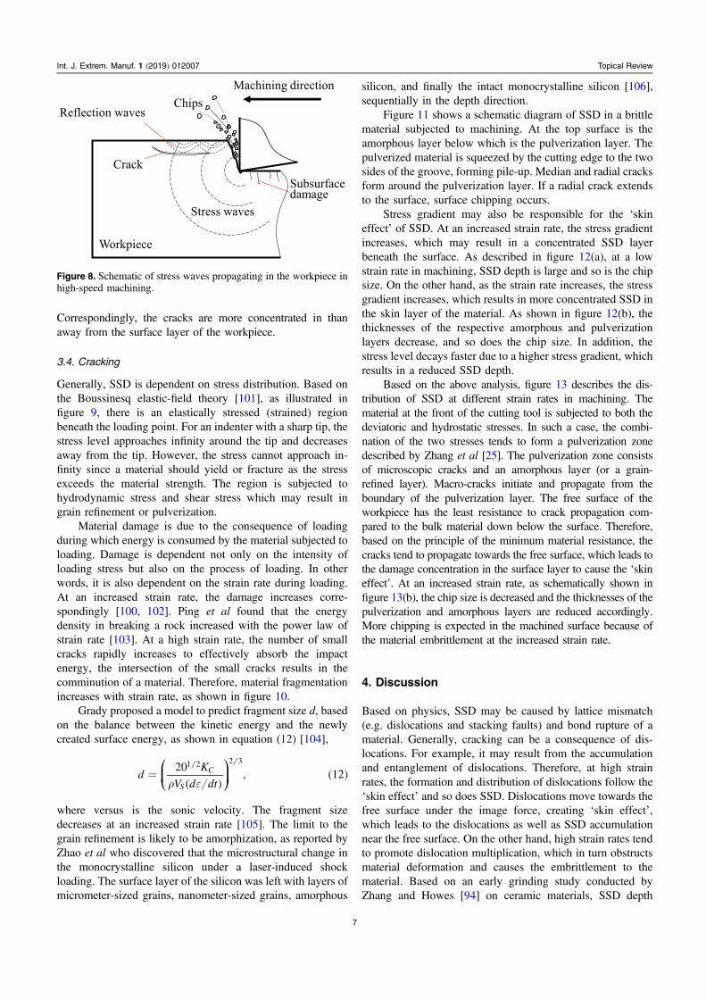
Correspondingly, the cracks are more concentrated in thanaway from the surface layer of the workpiece.
3.4. Cracking
Generally, SSD is dependent on stress distribution. Based onthe Boussinesq elastic-field theory [101], as illustrated infigure 9, there is an elastically stressed (strained) regionbeneath the loading point. For an indenter with a sharp tip, thestress level approaches infinity around the tip and decreasesaway from the tip. However, the stress cannot approach in-finity since a material should yield or fracture as the stressexceeds the material strength. The region is subjected tohydrodynamic stress and shear stress which may result ingrain refinement or pulverization.
Material damage is due to the consequence of loadingduring which energy is consumed by the material subjected toloading. Damage is dependent not only on the intensity ofloading stress but also on the process of loading. In otherwords, it is also dependent on the strain rate during loading.At an increased strain rate, the damage increases corre-spondingly [100, 102]. Ping et al found that the energydensity in breaking a rock increased with the power law ofstrain rate [103]. At a high strain rate, the number of smallcracks rapidly increases to effectively absorb the impactenergy, the intersection of the small cracks results in thecomminution of a material. Therefore, material fragmentationincreases with strain rate, as shown in figure 10.
Grady proposed a model to predict fragment size d, basedon the balance between the kinetic energy and the newlycreated surface energy, as shown in equation (12) [104],
dK
V d dt
20, 12C
S
1 2 2 3
r e=
⎛⎝⎜
⎞⎠⎟( )
( )
where versus is the sonic velocity. The fragment sizedecreases at an increased strain rate [105]. The limit to thegrain refinement is likely to be amorphization, as reported byZhao et al who discovered that the microstructural change inthe monocrystalline silicon under a laser-induced shockloading. The surface layer of the silicon was left with layers ofmicrometer-sized grains, nanometer-sized grains, amorphous
silicon, and finally the intact monocrystalline silicon [106],sequentially in the depth direction.
Figure 11 shows a schematic diagram of SSD in a brittlematerial subjected to machining. At the top surface is theamorphous layer below which is the pulverization layer. Thepulverized material is squeezed by the cutting edge to the twosides of the groove, forming pile-up. Median and radial cracksform around the pulverization layer. If a radial crack extendsto the surface, surface chipping occurs.
Stress gradient may also be responsible for the ‘skineffect’ of SSD. At an increased strain rate, the stress gradientincreases, which may result in a concentrated SSD layerbeneath the surface. As described in figure 12(a), at a lowstrain rate in machining, SSD depth is large and so is the chipsize. On the other hand, as the strain rate increases, the stressgradient increases, which results in more concentrated SSD inthe skin layer of the material. As shown in figure 12(b), thethicknesses of the respective amorphous and pulverizationlayers decrease, and so does the chip size. In addition, thestress level decays faster due to a higher stress gradient, whichresults in a reduced SSD depth.
Based on the above analysis, figure 13 describes the dis-tribution of SSD at different strain rates in machining. Thematerial at the front of the cutting tool is subjected to both thedeviatoric and hydrostatic stresses. In such a case, the combi-nation of the two stresses tends to form a pulverization zonedescribed by Zhang et al [25]. The pulverization zone consistsof microscopic cracks and an amorphous layer (or a grain-refined layer). Macro-cracks initiate and propagate from theboundary of the pulverization layer. The free surface of theworkpiece has the least resistance to crack propagation com-pared to the bulk material down below the surface. Therefore,based on the principle of the minimum material resistance, thecracks tend to propagate towards the free surface, which leads tothe damage concentration in the surface layer to cause the ‘skineffect’. At an increased strain rate, as schematically shown infigure 13(b), the chip size is decreased and the thicknesses of thepulverization and amorphous layers are reduced accordingly.More chipping is expected in the machined surface because ofthe material embrittlement at the increased strain rate.
4. Discussion
Based on physics, SSD may be caused by lattice mismatch(e.g. dislocations and stacking faults) and bond rupture of amaterial. Generally, cracking can be a consequence of dis-locations. For example, it may result from the accumulationand entanglement of dislocations. Therefore, at high strainrates, the formation and distribution of dislocations follow the‘skin effect’ and so does SSD. Dislocations move towards thefree surface under the image force, creating ‘skin effect’,which leads to the dislocations as well as SSD accumulationnear the free surface. On the other hand, high strain rates tendto promote dislocation multiplication, which in turn obstructsmaterial deformation and causes the embrittlement to thematerial. Based on an early grinding study conducted byZhang and Howes [94] on ceramic materials, SSD depth
Figure 8. Schematic of stress waves propagating in the workpiece inhigh-speed machining.
7
Int. J. Extrem. Manuf. 1 (2019) 012007 Topical Review

decreases with an increase in the material brittleness. There-fore, the ‘skin effect’ of the dislocations and the materialembrittlement due to dislocation multiplication lead to the‘skin effect’ of SSD at high strain rates.
Practically, numerous factors, such as strain and strainrate, dislocation movement, crack initiation and propagation,material phase transformation, stress distribution, and stresswave propagation, as well as the changes in the materialproperties, are collectively responsible for the ‘skin effect’ ofSSD. It is difficult to analyze the ‘skin effect’ from one factoralone. However, the effect can be comprehended from theaspect of energy dissipation.
From the energy point of view, machining is recognizedas an energy rebalance process. A system with the minimumenergy level is the most stable. A material in machining isactivated with an elevated energy that has a tendency totransform into the most stable state of the minimum energy.The material damage, including dislocations and cracking, isa way of energy relaxation. Based on the minimum energyprinciple, the damage tends to move towards where the
Figure 9. Schematics of (a) a stressed (strained) region around the loading point; (b) stress (strain) distribution in the depth direction.
Figure 10. Fragments of sandstone impacted at different strain rates. Reproduced with permission from [102].
Figure 11. Subsurface damage of brittle materials.
8
Int. J. Extrem. Manuf. 1 (2019) 012007 Topical Review

energy requirement is the lowest for damage formation. Sincethe free surface has the lowest energy for damage formationcompared to other locations within the material, damage tendsto propagate towards the free surface.
In this paper, the effect of temperature rise on damageformation in machining is temporarily put aside to simplify thediscussion. The temperature in machining indeed affects themechanical behavior of a material, such as dislocation kinetics[107, 108], stress wave propagation, and eventually surfaceintegrity of a machined part. Specifically, in the conventionalmachining of ductile materials, temperature has a notable effecton the generation of the surface metamorphic layer [17, 20, 109].Whereas at the high strain-rate machining, the temperature effectcan be neglected. The reason is expatiated in the following.
Temperature rise is a reflection of the heat generation inmachining. The heat in machining of a ductile material ismainly generated from material shear and friction. However,at a high strain rate, the material is embrittled, which directlycontributes to the heat reduction from the decreased shear andfriction and thus to the temperature reduction accordingly.
The ‘skin effect’ of damage at high strain rates provides aguidance for many industrial applications. In machining, the‘skin effect’ allows to acquire the desired surface quality of amachined part by increasing strain rate in machining, such asultrasonic assisted machining and peening.
5. Concluding remarks and outlook
This paper proposes the ‘skin effect’ of material damage athigh strain rates for the first time. The ‘skin effect’ isapplicable not only to the hard and brittle materials, but also
Figure 12. Subsurface damage evolution with strain rate.
Figure 13. Propagation of macro-cracks at different strain rates.
9
Int. J. Extrem. Manuf. 1 (2019) 012007 Topical Review

to most other engineering materials, such as metallic materi-als. The paper draws the following concluding remarks.
(a) The ‘skin effect’ of damage is obtained at a high strainrate in a loading process.
(b) High strain rate results in an increase in materialbrittleness.
(c) Brittleness is a material property that contributes to the‘skin effect’ of damage in a loading process;
The ‘skin effect’ of damage can have numerous industrialapplications. One direct application is the HSM of the diffi-cult-to-machine materials, such as ceramics, high strengthmetals, and composite materials. Nevertheless, many issuesremain unresolved, such as how high the stain rate should bein order to suppress SSD in machining. Other issues mayinclude dislocation nucleation and motion, interactions amongdislocations during loading at a high strain rate.
With a rapid development of the modern testing equip-ment and techniques, to have well-controlled testing condi-tions comes to reality. High-speed and high precision machinetools are readily available. In addition, the state-of-the-artcharacterization facilities, such as the focused ion beamdevice in combination with high-resolution transmissionelectron microscopes (HRTEM), the cathode luminescencedevice in combination with SEM, are also readily accessible.With the aforementioned modern testing equipment andtechniques, the unresolved issues are expected to be resolved,and the underlying physical mechanisms of the ‘skin effect’ ofdamage can further be explored in the near future.
Acknowledgments
The authors would like to acknowledge the supports by theNational Natural Science Foundation of China (Grant No.51575084) and the Peacock Program of Shenzhen (Grant No.KQJSCX20180322152221965).
References
[1] Gao Y 2014 Study on high strian rate deformation of alumina,silicon carbide ceramics and Al2O3/SiC nanocompositesSchool of Materials Science and Technology (Beijing: ChinaUniversity of Geosciences)
[2] Sternberg J 1989 Material properties determining theresistance of ceramics to high velocity penetration J. Appl.Phys. 65 3417–24
[3] Ulutan D and Ozel T 2011 Machining induced surfaceintegrity in titanium and nickel alloys: a review Int. J. Mach.Tools Manuf. 51 250–80
[4] Thakur A and Gangopadhyay S 2016 State-of-the-art insurface integrity in machining of nickel-based super alloysInt. J. Mach. Tools Manuf. 100 25–54
[5] Hahn P O 2001 The 300 mm silicon wafer—a cost andtechnology challenge Microelectron. Eng. 56 3–13
[6] Wang Z, Tian B, Pantouvaki M, Guo W, Absil P,Van Campenhout J, Merckling C and Thourhout D V 2015Room-temperature InP distributed feedback laser arraydirectly grown on silicon Nat. Photon. 9 837
[7] Pei Z J, Billingsley S R and Miura S 1999 Grinding inducedsubsurface cracks in silicon wafers Int. J. Mach. ToolsManuf. 39 1103–16
[8] Masuko K et al 2014 Achievement of more than 25%conversion efficiency with crystalline silicon heterojunctionsolar cell IEEE J. Photovolt. 4 1433–5
[9] Taguchi M, Yano A, Tohoda S, Matsuyama K, Nakamura Y,Nishiwaki T, Fujita K and Maruyama E 2014 24.7% recordefficiency hit solar cell on thin silicon wafer IEEE J.Photovolt. 4 96–9
[10] Ryu H Y, Jeon K S, Kang M G, Yuh H K, Choi Y H andLee J S 2017 A comparative study of efficiency droop andinternal electric field for InGaN blue lighting-emittingdiodes on silicon and sapphire substrates Sci. Rep. 7 44814
[11] Zang Z, Zeng X, Du J, Wang M and Tang X 2016Femtosecond laser direct writing of microholes onroughened ZnO for output power enhancement of InGaNlight-emitting diodes Opt. Lett. 41 3463–6
[12] Lee Y J, Hwang J M, Hsu T C, Hsieh M H, Jou M J, Lee B J,Lu T C, Kuo H C and Wang S C 2006 Enhancing the outputpower of GaN-based LEDs grown on wet-etched patternedsapphire substrates IEEE Photonics Technol. Lett. 18 1152–4
[13] Yin Z, Huang C, Yuan J, Zou B, Liu H and Zhu H 2015Cutting performance and life prediction of an Al2O3/TiCmicro-nano-composite ceramic tool when machiningaustenitic stainless steel Ceram. Int. 41 7059–65
[14] Shalaby M A, El Hakim M A, Abdelhameed M M,Krzanowski J E, Veldhuis S C and Dosbaeva G K 2014Wear mechanisms of several cutting tool materials in hardturning of high carbon-chromium tool steel Tribol. Int. 70148–54
[15] Li H N, Yu T B, Zhu L D and Wang W S 2016 Evaluation ofgrinding-induced subsurface damage in optical glass BK7J. Mater. Process. Technol. 229 785–94
[16] Che-Haron C H and Jawaid A 2005 The effect of machiningon surface integrity of titanium alloy Ti-6% Al-4% VJ. Mater. Process. Technol. 166 188–92
[17] Thakur A, Mohanty A and Gangopadhyay S 2014Comparative study of surface integrity aspects of Incoloy825 during machining with uncoated and CVD multilayercoated inserts Appl. Surf. Sci. 320 829–37
[18] Herbert C, Axinte D, Hardy M and Brown P D 2012Investigation into the characteristics of white layersproduced in a nickel-based superalloy from drillingoperations Mach. Sci. Technol. 16 40–52
[19] Imran M, Mativenga P, Gholinia A and Withers P 2015Assessment of surface integrity of Ni superalloy afterelectrical-discharge, laser and mechanical micro-drillingprocesses Int. J. Adv. Manuf. Technol. 79 1303–11
[20] Aramcharoen A, Mativenga P T and Manufacturing, L.P.Group 2007 White layer formation and hardening effects inhard turning of H13 tool steel with CrTiAlN and CrTiAlN/MoST-coated carbide tools Int. J. Adv. Manuf. Technol.36 650
[21] Zhang B, Shen W, Liu Y, Tang X and Wang Y 1997Microstructures of surface white layer and internal whiteadiabatic shear band Wear 211 164–8
[22] Wang C, Fang Q, Chen J, Liu Y and Jin T 2016 Subsurfacedamage in high-speed grinding of brittle materialsconsidering kinematic characteristics of the grinding processInt. J. Adv. Manuf. Technol. 83 937–48
[23] Yamaguchi H, Srivastava A K, Tan M A, Riveros R E andHashimoto F 2012 Magnetic abrasive finishing of cuttingtools for machining of titanium alloys CIRP Ann. 61 311–4
[24] Zhang B, Tokura H and Yoshikawa M 1988 Study on surfacecracking of alumina scratched by single-point diamondsJ. Mater. Sci. 23 3214–24
[25] Zhang B and Howes T D 1994 Material-removal mechanismsin grinding ceramics CIRP Ann. 43 305–8
10
Int. J. Extrem. Manuf. 1 (2019) 012007 Topical Review

[26] Bifano T G, Dow T A and Scattergood R O 1991 Ductile-regime grinding: a new technology for machining brittlematerials J. Eng. Ind. 113 184–9
[27] Zhang B, Zheng X L, Tokura H and Yoshikawa M 2003Grinding induced damage in ceramics J. Mater. Process.Technol. 132 353–64
[28] Zhang B and Peng X 2000 Grinding damage prediction forceramics via CDM model J. Manuf. Sci. Eng. 122 51–8
[29] Zhang B 1988 Study on Surface Characteristics of non-oxieceramics scratched by single point diamond J. Japan Soc.Precis. Eng. 54 587
[30] Zhang B, Tokura H and Yoshikawa M 1988 Study on surfacedamage of ceramics ground with diamond wheel J. JapanSoc. Precision. Eng 54 1537–43
[31] Liang Z, Wang X, Wu Y, Xie L, Jiao L and Zhao W 2013Experimental study on brittle–ductile transition in ellipticalultrasonic assisted grinding (EUAG) of monocrystalsapphire using single diamond abrasive grain Int. J. Mach.Tools Manuf. 71 41–51
[32] Zhang J H, Zhao Y, Tian F Q, Zhang S and Guo L S 2015Kinematics and experimental study on ultrasonic vibration-assisted micro end grinding of silica glass Int. J. Adv. Manuf.Technol. 78 1893–904
[33] Shen J Y, Wang J Q, Jiang B and Xu X P 2015 Study on wearof diamond wheel in ultrasonic vibration-assisted grindingceramic Wear 332-333 788–93
[34] Gao G F, Zhao B, Xiang D H and Kong Q H 2009 Researchon the surface characteristics in ultrasonic grinding nano-zirconia ceramics J. Mater. Process. Technol. 209 32–7
[35] Wang Y, Lin B, Wang S and Cao X 2014 Study on thesystem matching of ultrasonic vibration assisted grinding forhard and brittle materials processing Int. J. Mach. ToolsManuf. 77 66–73
[36] Wang J, Feng P, Zhang J, Zhang C and Pei Z 2016 Modelingthe dependency of edge chipping size on the materialproperties and cutting force for rotary ultrasonic drilling ofbrittle materials Int. J. Mach. Tools Manuf. 101 18–27
[37] Cao J, Wu Y, Lu D, Fujimoto M and Nomura M 2014Material removal behavior in ultrasonic-assisted scratchingof SiC ceramics with a single diamond tool Int. J. Mach.Tools Manuf. 79 49–61
[38] Sun Z, To S and Yu K M 2018 An investigation in the ultra-precision fly cutting of freeform surfaces on brittle materialswith high machining efficiency and low tool wear Int. J.Adv. Manuf. Technol. 101 1583–93
[39] Shi K, Ren J, Zhang D, Zhai Z and Huang X 2017 Tool wearbehaviors and its effect on machinability in dry high-speedmilling of magnesium alloy Int. J. Adv. Manuf. Technol. 903265–73
[40] Chen J, Fang Q and Li P 2015 Effect of grinding wheelspindle vibration on surface roughness and subsurfacedamage in brittle material grinding Int. J. Mach. ToolsManuf. 91 12–23
[41] M’Saoubi R, Larsson T, Outeiro J, Guo Y, Suslov S,Saldana C and Chandrasekar S 2012 Surface integrityanalysis of machined Inconel 718 over multiple length scalesCIRP Ann. 61 99–102
[42] Jin D, Liu Z, Yi W and Su G 2011 Influence of cutting speedon surface integrity for powder metallurgy nickel-basedsuperalloy FGH95 Int. J. Adv. Manuf. Technol. 56553–9
[43] Du J, Liu Z and Lv S 2014 Deformation-phase transformationcoupling mechanism of white layer formation in high speedmachining of FGH95 Ni-based superalloy Appl. Surf. Sci.292 197–203
[44] Yang H C, Chen Z T and Zhou Z T 2015 Influence of cuttingspeed and tool wear on the surface integrity of the titaniumalloy Ti-1023 during milling Int. J. Adv. Manuf. Technol. 781113–26
[45] Kaynak Y, Karaca H E and Jawahir I S 2015 Cutting speeddependent microstructure and transformation behavior ofNiTi alloy in dry and cryogenic machining J. Mater. Eng.Perform. 24 452–60
[46] Davim J P and Maranhão C 2009 A study of plastic strain andplastic strain rate in machining of steel AISI 1045 usingFEM analysis Mater. Des. 30 160–5
[47] Shaw M C 2005 Metal Cutting Principles–Oxford Series onAdvanced Manufacturing (New York: Oxford UniversityPress)
[48] Wang B, Liu Z, Su G, Song Q and Ai X 2015 Investigationsof critical cutting speed and ductile-to-brittle transitionmechanism for workpiece material in ultra-high speedmachining Int. J. Mech. Sci. 104 44–59
[49] Li Y et al 2011 Morphology and distribution of subsurfacedamage in optical fused silica parts: bound-abrasive grindingAppl. Surf. Sci. 257 2066–73
[50] Esmaeilzare A, Rahimi A and Rezaei S M 2014 Investigationof subsurface damages and surface roughness in grindingprocess of Zerodur® glass-ceramic Appl. Surf. Sci. 31367–75
[51] Yao Z, Gu W and Li K 2012 Relationship between surfaceroughness and subsurface crack depth during grinding ofoptical glass BK7 J. Mater. Process. Technol. 212969–76
[52] Wang J, Zhang C, Feng P and Zhang J 2016 A model forprediction of subsurface damage in rotary ultrasonic facemilling of optical K9 glass Int. J. Adv. Manuf. Technol. 83347–55
[53] Gao Y, Ge P and Liu T 2016 Experiment study onelectroplated diamond wire saw slicing single-crystal siliconMater. Sci. Semicond. Process. 56 106–14
[54] Wu C, Li B, Liu Y, Pang J and Liang S Y 2017 Strain rate-sensitive analysis for grinding damage of brittle materialsInt. J. Adv. Manuf. Technol. 89 2221–9
[55] Lakhdari F, Bouzid D, Belkhir N and Herold V 2017 Surfaceand subsurface damage in Zerodur® glass ceramic duringultrasonic assisted grinding Int. J. Adv. Manuf. Technol. 901993–2000
[56] Zhang L, Liu W, Chen J and Fang Q 2018 Subsurfacedamage in grinding of brittle materials consideringmachining parameters and spindle dynamics Int. J. Adv.Manuf. Technol. 97 3723–34
[57] Lv D, Huang Y, Tang Y and Wang H 2013 Relationshipbetween subsurface damage and surface roughness ofglass BK7 in rotary ultrasonic machining andconventional grinding processes Int. J. Adv. Manuf.Technol. 67 613–22
[58] Liu T, Ge P, Bi W and Gao Y 2017 Subsurface crack damagein silicon wafers induced by resin bonded diamond wiresawing Mater. Sci. Semicond. Process. 57 147–56
[59] Teomete E 2013 Wire saw process-induced surface damagecharacterization Arab. J. Sci. Eng. 38 1209–15
[60] Pawade R S, Joshi S S and Brahmankar P K 2008 Effect ofmachining parameters and cutting edge geometry on surfaceintegrity of high-speed turned Inconel 718 Int. J. Mach.Tools Manuf. 48 15–28
[61] Kishawy H A and Elbestawi M A 2001 Tool wear and surfaceintegrity during high-speed turning of hardened steel withpolycrystalline cubic boron nitride tools Proc. Inst. Mech.Eng. B 215 755–67
[62] Veldhuis S C, Dosbaeva G K, Elfizy A, Fox-Rabinovich G S andWagg T 2010 Investigations of white layer formation duringmachining of powder metallurgical Ni-based ME 16 superalloyJ. Mater. Eng. Perform. 19 1031–6
[63] Orowan E 1940 Problems of plastic gliding Proc. Phys. Soc.52 8
[64] Abu Al-Rub R K and Voyiadjis G Z 2006 A physically basedgradient plasticity theory Int. J. Plast. 22 654–84
11
Int. J. Extrem. Manuf. 1 (2019) 012007 Topical Review

[65] Loveridge-Smith A et al 2001 Anomalous elastic response ofsilicon to uniaxial shock compression on nanosecond timescales Phys. Rev. Lett. 86 2349–52
[66] Hull D and Bacon D J 2001 Introduction to Dislocations(Oxford: Butterworth-Heinemann)
[67] Chen L 2015 The role of temperature and microstructure onthe dynamic strength of materials Physics (London: ImperialCollege)
[68] Brailsford A D 1972 Anharmonicity contributions todislocation drag J. Appl. Phys. 43 1380–93
[69] Gorman J A, Wood D S and Vreeland T Jr 1969 Mobility ofdislocations in aluminum J. Appl. Phys. 40 833–41
[70] Nadgornyi E 1988 Dislocation dynamics and mechanicalproperties of crystals Prog. Mater. Sci. 31 1–530
[71] Follansbee P S and Kocks U F 1988 A constitutivedescription of the deformation of copper based on the use ofthe mechanical threshold stress as an internal state variableActa Metall. 36 81–93
[72] Johnston W G and Gilman J J 1959 Dislocation velocities,dislocation densities, and plastic flow in lithium fluoridecrystals J. Appl. Phys. 30 129–44
[73] Gurrutxaga-Lerma B, Balint D S, Dini D, Eakins D E andSutton A P 2014 chapter two-dynamic discrete dislocationplasticity Advances in Applied Mechanics ed S P A Bordas(Amsterdam: Elsevier) pp 93–224
[74] Meyers M A 1994 Dynamic Behavior of Materials (NewYork: Wiley)
[75] Taylor G I 1938 Plastic strain in metals J. Institute Metals 62307–24
[76] Shigley J E and Mischke C R 1989 Mechanical EngineeringDesign 5th edn (New York: McGraw-Hill)
[77] Wang B, Liu Z, Su G and Ai X 2015 Brittle removalmechanism of ductile materials with ultrahigh-speedmachining J. Manuf. Sci. Eng. 137 061002
[78] Zhou L, Shimizu J, Muroya A and Eda H 2003 Materialremoval mechanism beyond plastic wave propagation ratePrecis. Eng. 27 109–16
[79] Wang B and Liu Z 2016 Investigations on deformation andfracture behavior of workpiece material during high speedmachining of 7050-T7451 aluminum alloy CIRP J. Manuf.Sci. Technol. 14 43–54
[80] Lawn B R and Marshall D B 1979 Hardness, toughness, andbrittleness: an indentation analysis J. Am. Ceram. Soc. 62347–50
[81] Zhao S, Wang H, Gu J, Guo N, Shao L, Zhang Y, Yao K andChen N 2018 High strain rate sensitivity of hardness inTi–Zr–Hf–Be–(Cu/Ni) high entropy bulk metallic glassesJ. Alloys Compd. 742 312–7
[82] Wang Q, Liu Z, Wang B, Song Q and Wan Y 2016Evolutions of grain size and micro-hardness during chipformation and machined surface generation for Ti-6Al-4V inhigh-speed machining Int. J. Adv. Manuf. Technol. 821725–36
[83] dos Santos T, Rossi R, Maghous S and Rosa P A R 2018Experimental procedure and simplified modeling for thehigh strain-rate and transient hardness evolution ofaluminum AA1050 Mech. Mater. 122 42–57
[84] Shen J, Kondoh K, Jones T L, Mathaudhu S N,Kecskes L J and Wei Q 2016 Effect of strain rate on themechanical properties of magnesium alloy AMX602 Mater.Sci. Eng. A 649 338–48
[85] Sun J and Guo Y B 2009 A comprehensive experimentalstudy on surface integrity by end milling Ti–6Al–4VJ. Mater. Process. Technol. 209 4036–42
[86] Limbach R, Rodrigues B P and Wondraczek L 2014 Strain-rate sensitivity of glasses J. Non-Cryst. Solids 404 124–34
[87] Bower A F, Fleck N A, Needleman A, Ogbonna N andEnderby J E 1993 Indentation of a power law creeping solidProc. R. Soc. A 441 97–124
[88] Goodall R and Clyne T W 2006 A critical appraisal of theextraction of creep parameters from nanoindentation dataobtained at room temperature Acta Mater. 54 5489–99
[89] Machado J J M, Marques E A S, Campilho R D S G andda Silva L F M 2017 Mode II fracture toughness of CFRP asa function of temperature and strain rate Composites B 114311–8
[90] Machado J, Marques E, Campilho R and da Silva L F 2017Mode I fracture toughness of CFRP as a function oftemperature and strain rate J. Compos. Mater. 51 3315–26
[91] Anton R J and Subhash G 2000 Dynamic Vickers indentationof brittle materials Wear 239 27–35
[92] Suresh S, Nakamura T, Yeshurun Y, Yang K H and Duffy J1990 Tensile fracture toughness of ceramic materials: effectsof dynamic loading and elevated temperatures J. Am.Ceram. Soc. 73 2457–66
[93] Liu Y, Li B, Wu C and Zheng Y 2016 Simulation-basedevaluation of surface micro-cracks and fracture toughness inhigh-speed grinding of silicon carbide ceramics Int. J. Adv.Manuf. Technol. 86 799–808
[94] Zhang B and Howes T D 1995 Subsurface evaluation ofground ceramics CIRP Ann. 44 263–6
[95] Weinberger C R and Cai W 2007 Computing image stress inan elastic cylinder J. Mech. Phys. Solids 55 2027–54
[96] Wang Z J et al 2015 Cyclic deformation leads to defecthealing and strengthening of small-volume metal crystalsProc. Natl Acad. Sci. 112 13502–7
[97] Eshelby J D and Mott N F 1951 The force on an elasticsingularity, philosophical transactions of the royal society oflondon Math. Phys. Sci. A 244 87–112
[98] Head A K 1953 X. The Interaction of dislocations andboundaries London, Edinburgh, Dublin Phil. Mag. J. Sci. 4492–4
[99] Hopkinson B 1921 The Pressure of a Blow (Cambridge:Cambridge University Press)
[100] Jiang F, Li Z, Wang N, Guo H and Xu X 2016 Research ondynamic characteristics of Shanxi black granite under highstrain rates J. Vib. Shock 35 177–82
[101] Boussinesq J 1970 Application des Potentiels l’Etude del’Equilibre et du Mouvement des Solides Elastiques’(Gauthier-Villars, Paris, 1885) ed S P Timoshenko andJ N Goodier Theory of Elasticity (New York: McGraw-Hill)pp 398–402
[102] Deng Y, Chen M, Jin Y and Zou D 2016 Investigation of thedynamic characteristics and energy consumption forbreaking rocks using the impact load Pet. Drill. Tech. 4427–32
[103] Ping Q, Luo X, Ma Q and Yuan P 2015 Broken energydissipation characteristics of sandstone specimens underimpact loads Chin. J. Rock Mech. Eng. 34 4197–203
[104] Grady D E 1982 Local inertial effects in dynamicfragmentation J. Appl. Phys. 53 322–5
[105] Lankford J and Blanchard C R 1991 Fragmentation of brittlematerials at high rates of loading J. Mater. Sci. 26 3067–72
[106] Zhao S, Hahn E N, Kad B, Remington B A, Wehrenberg C E,Bringa E M and Meyers M A 2016 Amorphization andnanocrystallization of silicon under shock compression ActaMater. 103 519–33
[107] Chen L Y, He M R, Shin J, Richter G and Gianola D S 2015Measuring surface dislocation nucleation in defect-scarcenanostructures Nat. Mater. 14 707
[108] Zhu T, Li J, Samanta A, Leach A and Gall K 2008Temperature and strain-rate dependence of surfacedislocation nucleation Phys. Rev. Lett. 100 025502
[109] Herbert C R J, Kwong J, Kong M C, Axinte D A,Hardy M C and Withers P J 2012 An evaluation of theevolution of workpiece surface integrity in hole makingoperations for a nickel-based superalloy J. Mater. Process.Technol. 212 1723–30
12
Int. J. Extrem. Manuf. 1 (2019) 012007 Topical Review