topix - wsm-17379 - workshop manual discovery 4 / lr4 (la
TRANSCRIPT

Published: 11-May-2011Auxiliary Heating -Torque Specifications
Description Nm lb-ftFuel fired booster heater exhaust bracket bolt 10 7Fuel fired booster heater 10 7
cardiagn.com

Item12345
Published: 03-Oct-2011Auxiliary Heating - Auxiliary Heater Description and Operation
COMPONENT LOCATIONS
DescriptionFFBH (fuel fired booster heater) fuel line connection to fuel tankFFBH auxiliary fuel pumpFFBH changeover valveFFBHFFBH receiver
INTRODUCTION
Auxiliary heating is provided by a FFBH (fuel fired booster heater), which boosts the temperature of the enginecoolant. Fuel for the FFBH is taken from the vehicle fuel tank, through a fuel line attached to the fuel pump module.An auxiliary fuel pump supplies the fuel at low pressure to the FFBH. In the FFBH, the fuel is burned and theresultant heat output is used to heat the engine coolant.
For remote operation, the system includes a FFBH receiver and a remote handset.
AUXILIARY FUEL PUMP
The auxiliary fuel pump regulates the fuel supply to the FFBH. The pump is a self priming, solenoid operated plungerpump, controlled by a pulse width modulation (PWM) signal from the control module in the FFBH. When the pump isde-energized, it provides a positive shut-off of the fuel supply.
Part Number-----
cardiagn.com

Item12345678910
Sectioned View of Auxiliary Fuel Pump
DescriptionFuel line connectorNon return valveSolenoid coilPlungerFilter insertFuel line connectorO-ring sealSpringPistonBush
The solenoid coil of the auxiliary fuel pump is installed around a housing which contains a plunger and piston. Thepiston locates in a bush, and a spring is installed on the piston between the bush and the plunger. A filter insert anda fuel line connector are installed in the inlet end of the housing. A non return valve and a fuel line connector areinstalled in the fuel outlet end of the housing.
While the solenoid coil is de-energized, the spring holds the piston and plunger in the closed position at the inlet endof the housing. An O-ring seal on the plunger provides a fuel tight seal between the plunger and the filter insert,preventing any flow through the pump. When the solenoid coil is energized, the piston and plunger move towards theoutlet end of the housing, until the plunger contacts the bush; fuel is then drawn in through the inlet connection andfilter. The initial movement of the piston also closes transverse drillings in the bush and isolates the pumpingchamber at the outlet end of the housing. Subsequent movement of the piston then forces fuel from the pumpingchamber through the non return valve and into the line to the FFBH. When the solenoid de-energizes, the springmoves the piston and plunger back towards the closed position. As the piston and plunger move towards the closedposition, fuel flows past the plunger and through the annular gaps and transverse holes in the bush to replenish thepumping chamber.
FFBH (Fuel Fired Booster Heater)
Part Number---------- ca
rdiagn.com

Item123456789
DescriptionAir inlet pipeElectrical connectorsExhaust mufflerExhaust pipeChangeover valve (if fitted)Coolant outlet connectionCoolant inlet connectionFuel supply lineCoolant circulation pump
Sectioned View of FFBH
Part Number---------
cardiagn.com

Item123456789101112
DescriptionCombustion air fanCoolant inletCoolant outletBurner insertCoolant temperature sensorsHeat exchangerExhaust outletFuel inletControl unitAir inletFuel evaporatorGlow plug / flame sensor
Coolant Circulation Pump
The coolant circulation pump is installed at the coolant inlet to the FFBH to assist the coolant flow through the FFBHand the vehicle heater core. The pump runs continuously while the FFBH is in standby or active operating modes.While the FFBH is inactive, coolant flow is reliant on the engine coolant pump. Operation of the FFBH coolantcirculation pump is controlled by a power feed direct from the FFBH control module.
Combustion Air Fan
The combustion air fan regulates the flow of air into the FFBH to support combustion of the fuel supplied by theauxiliary fuel pump and to purge and cool the FFBH after operation.
Burner Housing
Part Number------------
cardiagn.com
The burner housing contains the burner insert and also incorporates connections for the exhaust pipe, the coolantinlet from the coolant circulation pump and the coolant outlet to the vehicle heater core.
The burner insert incorporates the fuel combustion chamber, an evaporator and a glow pin and flame sensor. Fuelfrom the auxiliary fuel pump is supplied to an evaporator mat, where it evaporates and enters the combustionchamber to mix with air from the combustion air fan. The glow pin/flame sensor provides the ignition source of thefuel: air mixture and, once combustion is established, monitors the flame.
Heat Exchanger
The heat exchanger transfers heat generated by combustion to the coolant. Two sensors are installed in the heatexchanger casing to provide the control module with inputs of coolant temperature. The control module uses thetemperature inputs to control system operation.
Air Inlet Pipe
The air inlet pipe delivers air to the combustion chamber for fuel ignition.
Exhaust Pipe and Muffler
The exhaust pipe and muffler directs exhaust combustion gases to atmosphere. Exhaust vapor may be visible whenthe FFBH is running, depending on atmospheric conditions.
Control Module
The control module controls and monitors operation of the FFBH system. An internal flow of air from the combustionair fan ventilates the control module to prevent it overheating.
The control module communicates with other systems on the vehicle over the medium speed CAN (controller areanetwork) bus.
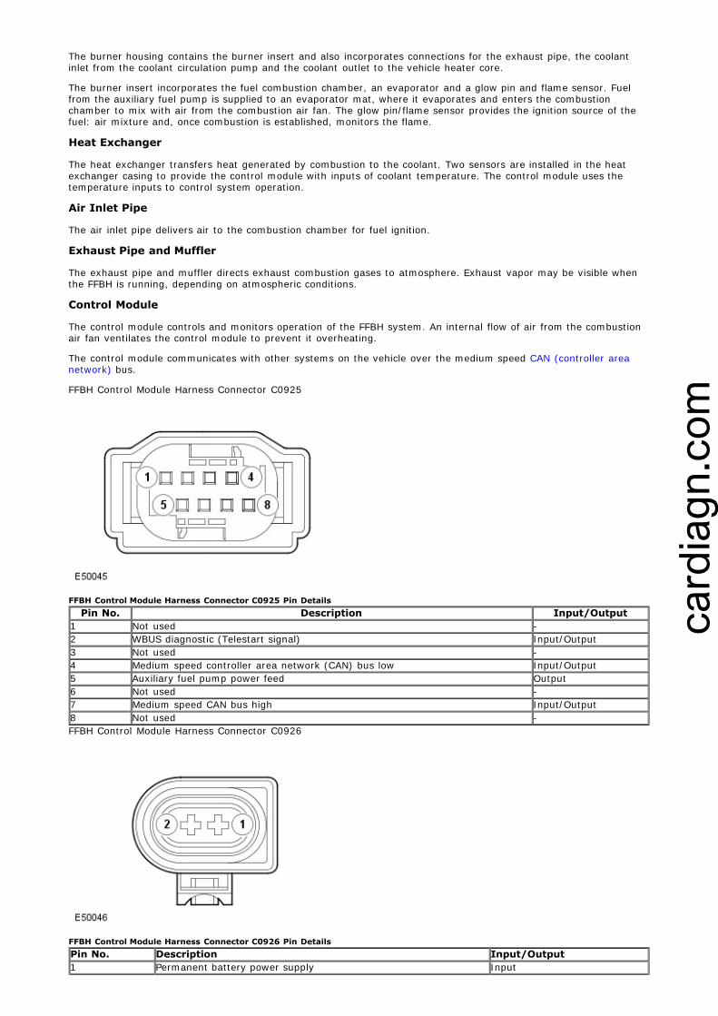
FFBH Control Module Harness Connector C0925
FFBH Control Module Harness Connector C0925 Pin DetailsPin No. Description Input/Output
1 Not used -2 WBUS diagnostic (Telestart signal) Input/Output3 Not used -4 Medium speed controller area network (CAN) bus low Input/Output5 Auxiliary fuel pump power feed Output6 Not used -7 Medium speed CAN bus high Input/Output8 Not used -FFBH Control Module Harness Connector C0926
FFBH Control Module Harness Connector C0926 Pin DetailsPin No. Description Input/Output1 Permanent battery power supply Input
cardiagn.com

2 Ground OutputChangeover Valve
The changeover valve is a normally open solenoid valve installed between the supply and return sides of the heatercoolant circuit. When de-energized, the changeover valve connects the heater coolant circuit to the engine coolantcircuit. When energized, the changeover valve isolates the heater coolant circuit from the engine coolant circuit.
The changeover valve is controlled by a power feed from the ATC (automatic temperature control) module.
FFBH Receiver
The FFBH receiver translates the FFBH request radio signals, relayed from the TV (television) antenna amplifier, into avoltage output to the FFBH unit. When a request for parked heating is received, the FFBH receiver outputs a batterypower feed to the FFBH unit. When a request to switch off parked heating is received, the FFBH receiver disconnectsthe power feed.
The FFBH receiver has a permanent power feed from the BJB (battery junction box) and is connected to the TVantenna amplifier by a coaxial cable.
FFBH Remote Handset
Item Description1 On button2 Off button3 LED (light emitting diode)4 AntennaThe FFBH remote handset allows parked heating to be remotely controlled up to a minimum of 100 m (328 ft) fromthe vehicle. 'On' and 'off' buttons activate and de-activate parked heating.
An LED:
Flashes green when parked heating is active.Flashes red after a start selection, if communication has not been established with the vehicle.Flashes orange when the remote handset battery needs replacing.
The FFBH remote handset is powered by a 3.3 V CR1/3N battery located under a cover on the rear of the handset.
Remote Handset Pairing:
Each remote handset must be 'paired' to the receiver to enable communications. Each handset has a uniqueidentification number which is stored by the receiver. The receiver can store up 3 handset identification numbers. If afourth handset is paired to the receiver, the receiver will replace the first paired handset number with that for thefourth handset in the receiver memory. Subsequently, the first paired handset will no longer be paired and will not berecognized by the receiver.
The following procedure details the pairing process:
NOTE: The pairing process relies on the FFBH receiver having the power supply removed and then the powersupply re-instated. The fuse method is the easiest method but it can also be achieved by battery disconnection orremoval of the harness connector from the receiver unit.
Remove mini-fuse F2 5A (telestart fuse) from the BJBWait for a minimum of 5 secondsReplace fuse to position F2 5A in the BJBWithin 5 seconds of replacing the fuse (and restoring the receiver power supply), press and hold the remotehandset OFF buttonConfirmation of successful pairing is displayed by the remote handset LED illuminating in a red color for 2seconds.
CONTROL DIAGRAM
NOTE: A = Hardwired connections; D = High speed CAN bus; F = RF transmission; N = Medium speed CANbus; P = MOST bus
cardiagn.com

Item12345678910111213141516171819
DescriptionFFBH remote handsetTV antennaTV tuner moduleFFBH receiverFFBHCJB (central junction box)FFBH coolant circulation pumpChangeover valve (if fitted)FFBH fuel pumpTouch screen displayECT (engine coolant temperature) sensorAmbient air temperature sensorECM (engine control module)IAM (integrated audio module)ATC moduleInstrument clusterIntegrated control panelBJBBattery
OPERATION
Part Number-------------------
cardiagn.com
The FFBH system operates in two modes:
Provides additional heating by boosting heater performance while the engine is running.If fitted; parked heating heats the passenger compartment or engine while the vehicle is parked with theengine off.
The ATC module disables FFBH operation if battery voltage is too low, as determined from an ambient airtemperature, dependent voltage-map. Where fitted, the battery monitoring system can also disable FFBH operationbased on the battery charge state with the engine off.
Parked Heating/Ventilation
Parked heating works in conjunction with parked ventilation. When parked heating/ventilation is selected, the vehicleinterior is either heated by parked heating or cooled by parked ventilation, depending on the ambient temperature.Parked heating occurs if the ambient temperature is less than 16 °C (61 °F); parked ventilation occurs if the ambienttemperature is 16 °C (61 °F) or more.
Parked heating/ventilation is controlled by direct selection on the (TSD) Touch Screen Display. This is achieved byusing the TSD to program one or two 'on/off' cycle start-times per day, and one 'on/off' cycle start-time further inthe future.
The direct selection and programmed time modes of operation are selected when the engine is stopped and thesmart key is in the vehicle. The key can then be removed and the vehicle locked. Any timed event will automaticallyrun without the key inside the vehicle.
In all operating modes, to prevent excessive drain on the battery, parked heating/ventilation is automatically de-activated after:
20 minutes in moderate climate conditions, andafter 30 minutes in climates where the ambient temperature regularly falls below minus 25 °C (minus 13 °F).
Parked ventilation is automatically de-activated when the ignition is switched on.
When programmed start times for parked heating/ventilation are entered on the TSD, the times are stored in theCJB.
If the engine is started while parked heating is on and:
the engine coolant temperature is equal to or more than the heater coolant temperature, parked heating isswitched off.the engine coolant temperature is less than the heater coolant temperature, parked heating remains on untilthe engine coolant temperature reaches the heater coolant temperature. The changeover valve also remainsclosed until the engine coolant temperature reaches the heater coolant temperature.
Parked heating/ventilation can also be operated by using the FFBH remote handset.
Programmed Parked Heating/Ventilation
At a programmed parked heating/ventilation start time, the EJB (engine junction box) sends a start signal to the ATCmodule on the medium speed CAN.
On receipt of the message:
If the ambient temperature is less than 16 °C (61 °F) and more than -20 °C (-4 °F), the ATC module initiatesparked heating and:
- Energizes the changeover valve.- Sends a CAN bus message to activate the FFBH.- Operates the blower at 47% of the maximum speed.- Operates the distribution doors in the heater assembly to direct the air to the footwells for
approximately 30 seconds, then to either only the windscreen, or to both the footwells and thewindscreen, depending on the ambient air temperature.
- Flashes the auto blower LED at 2 Hz.- If the ambient temperature is -20 °C (-4 °F) or below, the ATC module sends a CAN bus message to
activate the FFBH, but leaves the changeover valve de-energized and does not operate the blower ordistribution doors. Heated coolant is circulated around the engine and heater core(s) to heat the engineand improve engine starting.
- Once the FFBH coolant temperature is above a suitable threshold the cabin blower is switched on andcabin heating commenced.
If the ambient temperature is 16 °C (61 °F) or more, the ATC module initiates parked ventilation and:- Operates the blower at 47% of maximum speed.- Operates the distribution doors in the heater assembly to direct the air to the face level outlets.- Flashes the A/C (air conditioning) distribution LED at 2 Hz.
After 20 minutes in moderate climate conditions and after 30 minutes in climates where the ambient temperatureregularly falls below minus 25 °C (minus 13 °F), the ATC module stops the parked heating/ventilation:
If parked heating is active, the ATC module:- Sends a CAN bus message to de-activate the FFBH.- Switches off the blower.- Returns the distribution doors to the previous settings.- After 3 minutes, de-energizes the changeover valve.
If parked ventilation is active, the ATC module:- Switches off the blower.- Returns the distribution doors to the previous settings.
Remotely Selected Parked Heating/Ventilation
cardiagn.com

When parked heating/ventilation is selected 'on' with the remote handset, the request is received by the FFBHreceiver via the TV antenna and TV antenna amplifier. The FFBH receiver relays the request as a hardwired signal tothe FFBH control module. On receipt of the request, the FFBH control module sends the request to the ATC module onthe CAN bus. The ATC module then determines if parked heating or ventilation is required.
Operation of the FFBH is controlled by a status message from the automatic temperature control (ATC) module to thecontrol module. A similar status message, from the control module to the ATC module, advises the ATC module of thecurrent operating status of the FFBH.
While the engine is running, if the ambient air temperature is less than 9 °C (48 °F) and the engine coolanttemperature (ECT) is less than 75 °C (167 °F) the ATC module changes the status message from 'heater off' to'supplemental heat'. The control module then changes the status message it sends the ATC module to 'supplementalheat' and starts the FFBH. The control module will not start the FFBH, or will discontinue operation, if any of thefollowing occur:
The control module is in the error lockout mode (see Diagnostics, below).A crash message is received from the restraints control module (RCM). For additional information, refer to: Air Bag and Safety Belt Pretensioner Supplemental Restraint System(SRS) (501-20B, Description and Operation).A low fuel level message is received from the instrument cluster. For additional information, refer to: Information and Message Center (413-08, Description and Operation).The engine is not running, or stops running for approximately 4 seconds. The time delay is included for stallprotection.
If the control module does not start the FFBH, or discontinues operation, the status message to the ATC moduleremains at, or changes to, 'heater off'. If the ambient air temperature increases to 9 °C (48 °F), or the ECT increasesto 75 °C (167 °F), the ATC module cancels supplementary heating, by changing the status message to the controlmodule back to 'heater off'. The control module then cancels FFBH operation and changes the status message to theATC module to 'heater off'.
The FFBH is controlled at one of two heat output levels, 2.8 kW at part load combustion and 5 kW at full loadcombustion. The control module transmits the FFBH coolant temperature to the ATC module.
Start Sequence: At the beginning of a start sequence, the control module energizes the glow pin function of theglow pin and flame sensor, to pre heat the combustion chamber, starts the combustion air fan at slow speed andenergizes the coolant circulation pump. After approximately 30 seconds, the control module energizes the auxiliaryfuel pump at the starting sequence speed. The fuel delivered by the auxiliary fuel pump evaporates in the combustionchamber, mixes with air from the combustion air fan and is ignited by the glow pin and flame sensor. The controlmodule then progressively increases the speed of the auxiliary fuel pump and the combustion air fan. Oncecombustion is established the control module switches the glow pin and flame sensor from the glow pin function tothe flame sensing function to monitor combustion. From the beginning of the start sequence to stable combustion atfull load takes approximately 240 seconds.
Coolant Temperature Control: While the FFBH is running, the control module cycles the FFBH between full loadcombustion, part load combustion and a control idle phase of operation, depending on the temperature of the coolantin the heat exchanger.
Switching Point Diagram
cardiagn.com

Switching PointTemperature, °C (°F)Figure Item No. Description
1 Full load to part load 84 (183)2 Part load to control idle 88 (190)3 Control idle to part load 78 (172)4 Part load to full load 74 (165)After the start sequence, the control module maintains full load combustion until the coolant temperature reachesswitching point temperature 1. At this temperature, the control module decreases the speed of the auxiliary fuelpump and the combustion air fan to half speed, to produce part load combustion. The control module maintains partload combustion while the coolant temperature remains between switching point temperatures 2 and 4. At part loadcombustion the temperature of the coolant will increase or decrease depending on the amount of heat required toheat the vehicle interior. If the coolant temperature decreases to switching point temperature 4, the control moduleincreases the speed of the auxiliary fuel pump and the combustion air fan to full speed, to return to full loadcombustion. If the coolant temperature increases to switching point temperature 2, the control module enters acontrol idle phase of operation.
On entering the control idle phase, the control module immediately switches the auxiliary fuel pump off, to stopcombustion, and starts a timer for the combustion air fan. After a 2 minute cool down period, the control moduleswitches the combustion air fan off and then remains in the control idle phase while the coolant temperature remainsabove switching point temperature 3. If the coolant temperature decreases to switching point temperature 3, thecontrol module initiates a start to part load combustion. A start to part load combustion takes approximately 90seconds.
In order to limit the build up of carbon deposits on the glow pin and flame sensor, the control module also enters thecontrol idle phase if continuous combustion time exceeds 72 minutes (at part load, full load or a combination ofboth). After the cool down period, if the coolant is still in the temperature range that requires additional heat, thecontrol module restarts the FFBH.
Shutdown: To stop the FFBH, the control module de-energizes the auxiliary fuel pump to stop combustion, butcontinues operation of the combustion air fan and the coolant circulation pump for a time, to cool down the FFBH.The cool down time is 100 seconds if the FFBH was operating at part load combustion and 175 seconds if the FFBHwas operating at full load combustion.
DIAGNOSTICS
The control module monitors the FFBH system for faults. Any faults detected are stored in a volatile memory in thecontrol module, which can be interrogated by approved diagnostic equipment via the medium speed CAN bus. Amaximum of three faults and associated freeze frame data can be stored at any one time. If a further fault isdetected, the oldest fault is overwritten by the new fault.
The control module also incorporates an error lockout mode of operation that inhibits operation to prevent seriousfaults from causing further damage to the system. In the error lockout mode, the control module immediately stopsthe auxiliary fuel pump, and stops the combustion air fan and coolant circulation pump after a cool down time ofapproximately 2 minutes. Error lockout occurs for start sequence failures, combustion flameouts, heat exchangercasing overheat and if battery voltage is out of limits. The error lockout mode can be cleared using approveddiagnostic equipment.
Start Failure and Flameout: If a start sequence fails to establish combustion, or a flameout occurs aftercombustion is established, the control module immediately initiates another start sequence. The start failure orflameout is also recorded by an event timer in the control module. The event timer is increased by one after eachstart failure or flameout, and decreased by one if a subsequent start is successful. If the event timer increases tothree (over any number of drive cycles), the control module enters the error lockout mode.
Heat Exchanger Casing Overheat: To protect the system from excessive temperatures, the control module entersthe error lockout mode if the heat exchanger coolant temperature exceeds 125 °C (257 °F).
Battery Voltage Limits: 10.25 - 15.5 volts.
cardiagn.com

Published: 28-Aug-2012Auxiliary Heating - Fuel Fired Booster Heater Diagnosis and Testing
Principles of Operation
For a detailed description of the fuel fired booster heater system and operation, refer to the relevant Descriptionand Operation section of the workshop manual. REFER to: Auxiliary Heater (412-02 Auxiliary Heating,Description and Operation).
Inspection and Verification
CAUTION: Diagnosis by substitution from a donor vehicle is NOT acceptable. Substitution of controlmodules does not guarantee confirmation of a fault and may also cause additional faults in the vehicle beingchecked and/or the donor vehicle.
NOTE: Check and rectify basic faults before beginning diagnostic routines involving pinpoint tests.
1. Verify the customer concern.
2. Visually inspect for obvious signs of mechanical or electrical damage.
Visual InspectionMechanical Electrical
Fuel fired booster heater assembly- Coolant inlet/outlet- Exhaust- Fuel inlet- Air inlet
Auxiliary fuel pump and linesAuxiliary coolant pump
FusesHarnessesElectrical connector(s)Control module(s)
3. If an obvious cause for an observed or reported concern is found, correct the cause (if possible) beforeproceeding to the next step.
4. If the cause is not visually evident, check for Diagnostic Trouble Codes (DTCs) and refer to the DTCIndex.
DTC Index
For a list of Diagnostic Trouble Codes (DTCs) that could be logged on this vehicle, please refer to Section 100-00. REFER to: Diagnostic Trouble Code (DTC) Index - DTC: Fuel Fired Booster Heater Control Module (FFBH) (100-00, Description and Operation).
cardiagn.com

Published: 11-May-2011Auxiliary Heating - Fuel Fired Booster Heater TDV6 2.7L Diesel Removal and Installation
Removal
NOTE: Some variation in the illustrations may occur, but the essential information is always correct.
1. Disconnect the battery ground cable. For additional information, refer to: Specifications (414-00Charging System - General Information, Specifications).
2. WARNING: Make sure to support the vehicle with axlestands.
Raise and support the vehicle.
3. NOTE: Wheel shown removed for clarity.
Carefully release the wheel arch liner, to allowaccess to the fuel fired burner heater (FFBH)exhaust clamp retaining bolt.
4. NOTE: Components removed for clarity.
Release the exhaust clamp.
5. CAUTION: Before disconnecting orremoving components, ensure the area aroundthe joint faces and connections are clean. Plugopen connections to prevent contamination.
Disconnect the fuel fired booster heater fuelline.
Release the clip.
cardiagn.com

6. Lower the vehicle.
7. Release the power steering fluid reservoir.
8. Disconnect the fuel fired booster heater inletand outlet coolant hoses.
Clamp the hoses to minimise coolantloss.Release the 2 clips.
9. Remove the fuel fired booster heater.Disconnect the 2 electrical connectors.Remove the 3 bolts.Release the fuel pipe from the clip.
Installation1. Install the fuel fired booster heater.
Tighten the bolts to 10 Nm (7 lb.ft).Connect the electrical connectors.Secure the fuel pipe in the clip.
2. Connect the fuel fired booster heater coolant hoses.Secure with the clips.Remove the clamps.
3. Connect the fuel fired booster heater fuel hose.Secure with the clip.
4. Raise the vehicle.
5. Tighten the exhaust clamp.Tighten to 10 Nm (7 lb.ft).
6. Secure the wheel arch liner.Install the two retaining screws.Install the clip.
cardiagn.com

7. Lower the vehicle.
8. Install the power steering fluid reservoir.
9. Connect the battery ground cable. For additional information, refer to: Specifications (414-00Charging System - General Information, Specifications).
10. Connect exhaust extraction hoses to the tail pipes.
11. Remove the engine cover. For additional information, refer to: Engine Cover - 2.7L V6- TdV6 (501-05 Interior Trim and Ornamentation, Removaland Installation).
12. Loosen the coolant expansion tank bleed screw.
13. Loosen the cylinder head bleed hose bleedscrew.
14. Refill the cooling system.
15. Tighten the bleed screws to 14 Nm (10 lb.ft).
16. Fill the cooling system, keeping coolant to the upper levelmark of the expansion tank, until a steady stream ofcoolant is seen returning to the tank.
17. NOTE: When the coolant bleed is complete and priorto installing the expansion tank cap, top up the expansiontank to 30mm above the maximum level.
Install the coolant expansion tank cap.
18. WARNING: Release the cooling system pressure byslowly turning the expansion tank cap a quarter of a turn.Cover the expansion tank cap with a thick cloth to preventthe possibility of scalding. Failure to follow this instructionmay result in personal injury.
Start and run the engine.Hold the engine speed at 3,000 RPM for one minute.Return the engine to idle for five minutes.Hold the engine speed at 3,000 RPM for one minute.Run the engine until the thermostat opens.
cardiagn.com

Remove coolant expansion tank cap, allow float tosettle and top-up coolant if required. Install cap.
19. Switch the engine off and allow to cool.
20. Install the engine cover. For additional information, refer to: Engine Cover - 2.7L V6- TdV6 (501-05 Interior Trim and Ornamentation, Removaland Installation).
21. Check and top-up the coolant if required.
cardiagn.com
Published: 11-May-2011Auxiliary Heating - Fuel Fired Booster Heater TDV6 3.0L Diesel Removal and Installation
Removal
NOTES:
Removal steps in this procedure may contain installation details.
Some variation in the illustrations may occur, but the essential information is always correct.
1. Refer to: Specifications (414-00, Specifications).
2. WARNING: Make sure to support the vehicle with axlestands.
Raise and support the vehicle.
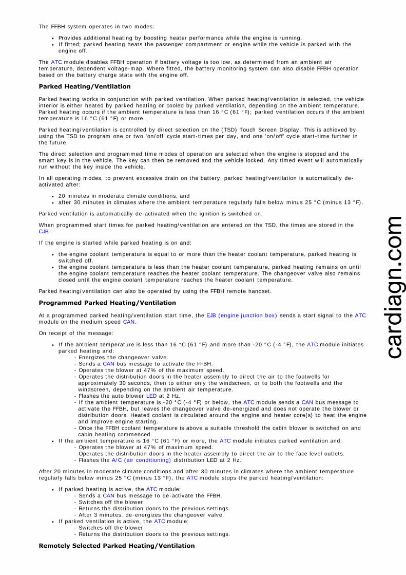
3. NOTE: Wheel shown removed for clarity.
Carefully release the wheel arch liner, toallow access to the fuel fired burnerheater (FFBH) exhaust clamp retainingbolt.
4.
NOTE: Components removed forclarity.
Torque: 10 Nm
5.
cardiagn.com

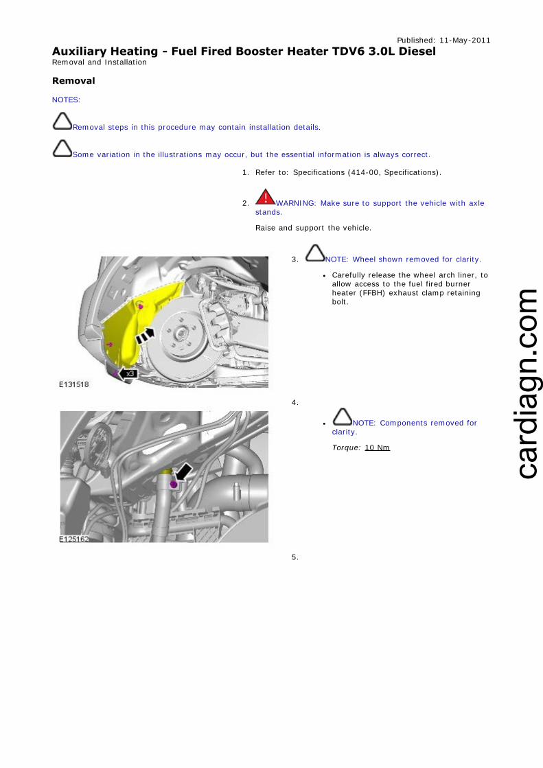
6. CAUTION: Be prepared to collect escapingcoolant.
Clamp the hoses to minimize coolantloss.
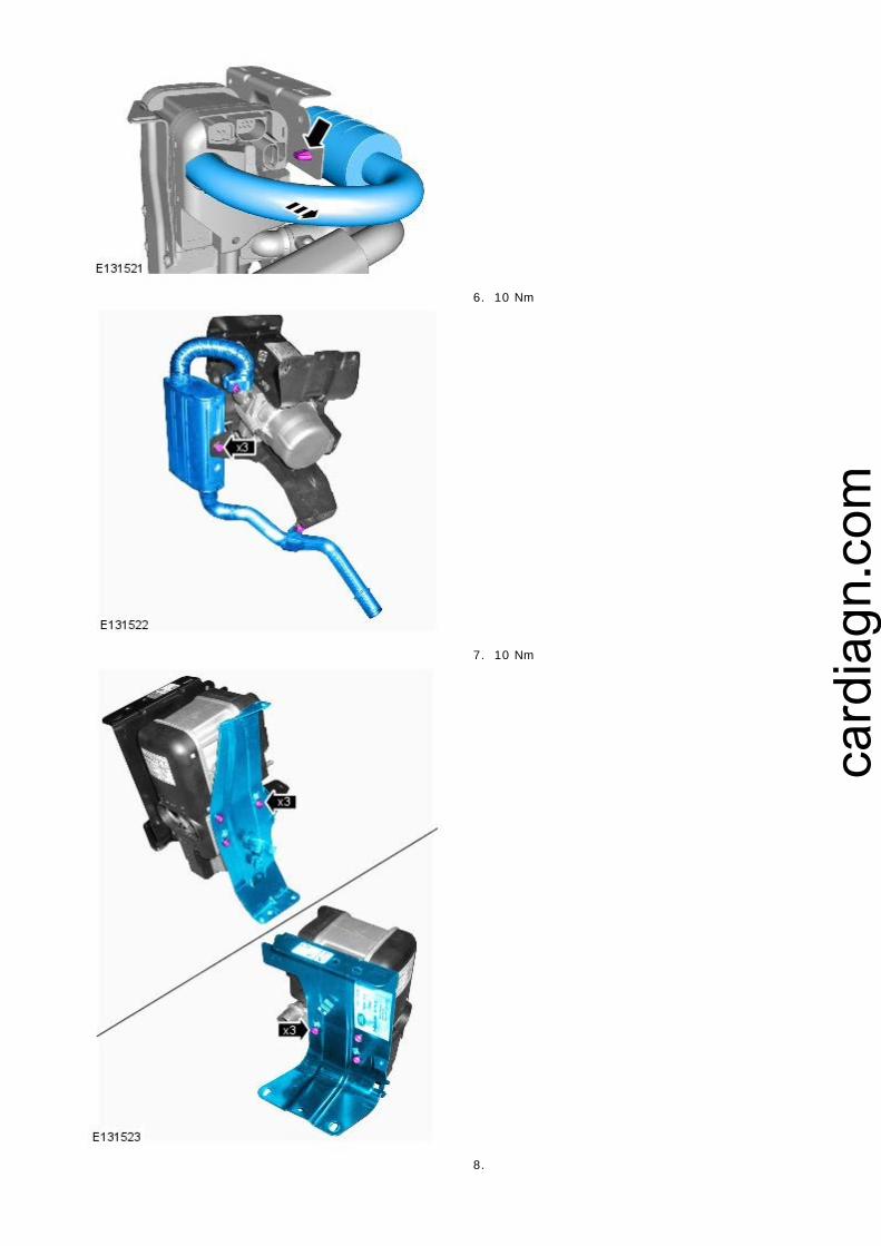
7.
8.
cardiagn.com

9. CAUTION: Before disconnecting orremoving components, ensure the area aroundthe joint faces and connections are clean. Plugopen connections to prevent contamination.
10. Torque: 10 Nm
Installation
1. To install, reverse the removal procedure.
cardiagn.com

2. Refer to: Engine Cover - 3.0L V6 - TdV6 (501-05, Removaland Installation).
3.
4.
5.
6. CAUTIONS:
Anti-freeze concentration must bemaintained at 50%.
Be prepared to collect escaping coolant.
Fill the coolant expansion tank until coolantappears through the bleed ports.
7. CAUTION: Be prepared to collect escapingcoolant.
Fill the coolant expansion tank until coolantappears through the bleed ports.
cardiagn.com

8. Set the heater controls to maximum.
9. Start the engine and continue to fill the coolant untilthe maximum level is reached.
10. CAUTION: Be prepared to collect escapingcoolant.
Fill the coolant expansion tank until coolantappears through the bleed ports.
11. Increase engine speed to 2500rpm and cycle between thisand idle.
12. Continue to top-up with coolant with the engine atidle.
13. CAUTION: Correct installation of theCoolant expansion tank cap can be obtained bytightening the cap until an audible click isheard.
14. Allow the engine to idle, until hot air is emitted at the faceregisters.
15. Once the front heater is warm, check if the rear heater iswarm (if equipped). If no heat is felt, increase the engine
cardiagn.com

speed to 3000 rpm for 30 seconds and return to idle.
16. CAUTION: Switch off the engine and allow the coolanttemperature to go cold.
17. Visually check the engine and cooling system for signs ofcoolant leakage.
18. WARNING: When releasing the cooling systempressure, cover the coolant expansion tank cap with a thickcloth.
CAUTIONS:
Since injury such as scalding could be caused byescaping steam or coolant, make sure the vehicle coolingsystem is cool prior to carrying out this procedure
Make sure the coolant level remains above the "COLDFILL RANGE" lower level mark.
NOTE: When the cooling system is warm, the coolantwill be approximately 10mm above the upper level mark onthe expansion tank with the cap removed.
Check and top-up the coolant if required.
19. Refer to: Engine Cover - 3.0L V6 - TdV6 (501-05, Removaland Installation).
cardiagn.com

Published: 11-May-2011Auxiliary Heating - Fuel Fired Booster Heater Glow Plug And BurnerAssembly TDV6 2.7L Diesel Removal and Installation
Removal
NOTES:
Removal steps in this procedure may contain installation details.
Some variation in the illustrations may occur, but the essential information is always correct.
1. Refer to: Specifications (414-00, Specifications).
2. WARNING: Make sure to support the vehicle with axlestands.
Raise and support the vehicle.
3. Refer to: Fuel Fired Booster Heater (412-02B, Removal andInstallation).
4. 7.5 Nm
5.
cardiagn.com
6. 10 Nm
7. 10 Nm
8.
cardiagn.com

9.
10.
11.
12. 7 Nm
cardiagn.com

Installation
1. To install, reverse the removal procedure.
2. Refer to: Fuel Fired Booster Heater (412-02B, Removal andInstallation).
cardiagn.com

Published: 11-May-2011Auxiliary Heating - Fuel Fired Booster Heater Glow Plug And BurnerAssembly TDV6 3.0L Diesel Removal and Installation
Removal
1. Refer to: Specifications (414-00, Specifications).
2. WARNING: Make sure to support the vehicle with axlestands.
Raise and support the vehicle.
3. Refer to: Fuel Fired Booster Heater - 3.0L V6 - TdV6 (412-02B, Removal and Installation).
4. NOTE: Where installed.
10 Nm
5. 7.5 Nm
cardiagn.com

6.
7. 10 Nm
8. 10 Nm
cardiagn.com

9.
10.
11.
cardiagn.com

12.
13. 7 Nm
Installation
1. To install, reverse the removal procedure.
2. Refer to: Fuel Fired Booster Heater - 3.0L V6 - TdV6 (412-02B, Removal and Installation).
cardiagn.com

Published: 30-Sep-2011Auxiliary Heating - Fuel Fired Booster Heater Receiver Unit Removal and Installation
Removal
NOTE: Removal steps in this procedure may contain installation details.
1. NOTE: RH side only.
Refer to: Rear Quarter Trim Panel (501-05, Removal andInstallation).
2.
3.
Installation
1. To install, reverse the removal procedure.
cardiagn.com

2. Using the diagnostic tool, calibrate the component.
cardiagn.com