topologies and measurements of turbulent flow in vertical
TRANSCRIPT

HAL Id: hal-00967167https://hal.archives-ouvertes.fr/hal-00967167
Submitted on 28 Mar 2014
HAL is a multi-disciplinary open accessarchive for the deposit and dissemination of sci-entific research documents, whether they are pub-lished or not. The documents may come fromteaching and research institutions in France orabroad, or from public or private research centers.
L’archive ouverte pluridisciplinaire HAL, estdestinée au dépôt et à la diffusion de documentsscientifiques de niveau recherche, publiés ou non,émanant des établissements d’enseignement et derecherche français ou étrangers, des laboratoirespublics ou privés.
Topologies and measurements of turbulent flow invertical slot fishways
Laurent Tarrade, Alain Texier, Laurent David, Michel Larinier
To cite this version:Laurent Tarrade, Alain Texier, Laurent David, Michel Larinier. Topologies and measurements ofturbulent flow in vertical slot fishways. Hydrobiologia, Springer, 2008, vol. 609, pp. 177-188.�10.1007/s10750-008-9416-y�. �hal-00967167�

Open Archive TOULOUSE Archive Ouverte (OATAO) OATAO is an open access repository that collects the work of Toulouse researchers and makes it freely available over the web where possible.
This is an author-deposited version published in : http://oatao.univ-toulouse.fr/ Eprints ID : 11272
To link to this article : doi:10.1007/s10750-008-9416-y URL : http://dx.doi.org/10.1051/kmae/2010022
To cite this version : Tarrade, Laurent and Texier, Alain and David, Laurent and Larinier, Michel Topologies and measurements of turbulent flow in vertical slot fishways. (2008) Hydrobiologia, vol. 609 (n° 1). pp. 177-188. ISSN 0018-8158
Any correspondance concerning this service should be sent to the repository
administrator: [email protected]

Topologies and measurements of turbulent flow in verticalslot fishways
Laurent Tarrade Æ Alain Texier Æ Laurent David ÆMichel Larinier
Abstract Several vertical slot fishways have been
built in France over the last 20 years. This type of pool
fish pass is generally very effective in ensuring passage
of the target species, particularly diadromous species.
However, visual observations have shown that certain
small species may be trapped in the large recirculation
zones and seem to have difficulty in rapidly passing
through very large pools. An experimental study was
undertaken to characterize the turbulent flow for
various configurations of vertical slot fishways and to
determine how they might be modified to facilitate the
passage of small species. The characteristics of mean
flow and turbulence were studied by particle image
velocimetry (PIV) for three slopes (I = 5%, 10%,
15%), three flow discharges (Q = 576, 736, 864 L/s)
and four pool widths (B = 1.7, 2, 2.3, 2.7 m). The
results showed that the flow pattern always follows one
of two topological models depending on the length/
width ratio of the pool. A strong link was found
between the calculated volumetric dissipated power
and the mean kinetic energy of velocity fluctuations
measured in the pools. In order to study the extent to
which the dimensions of recirculation zones can be
reduced, the effect of the insertion of vertical cylinders
within the pools was displayed by laser tomography.
Keywords Fishway � Turbulent flow �Recirculation zone � Turbulent kinetic energy �Shear layer
Notations
b Width of the slot (m)
B Width of the pool (m)
g Gravitational acceleration (m s-2)
h Water height (m)
I Slope of the channel (%)
k Turbulent kinetic energy (m2 s-2)
L Length of the pool (m)
q Water density (kg m-3)
Pv Volumetric dissipated power (W m-3)
Q Flow discharge (L s-1)
u,v Longitudinal and transverse instantaneous
velocities (m s-1)
u0,v0 Longitudinal and transverse RMS fluctuating
velocities (m s-1)
U,V Longitudinal and transverse mean velocities
(m s-1)
||V|| Velocity module (m s-1)
Guest editors: R. L. Welcomme & G. Marmulla
Hydropower, Flood Control and Water Abstraction:
Implications for Fish and Fisheries
L. Tarrade (&) � A. Texier � L. David
Laboratoire d’Etudes Aerodynamiques, Universite de
Poitiers, Teleport 2, Boulevard Marie et Pierre Curie, BP
30179, 86962 Futuroscope Chasseneuil Cedex, France
e-mail: [email protected]
M. Larinier
Institut de Mecanique des Fluides de Toulouse, Allee du
Professeur Camille Soula, 31400 Toulouse, France
DOI 10.1007/s10750-008-9416-y

X,Y,Z Longitudinal, transverse and vertical distance
(m s-1)
Dh Water level difference between two adjacent
pools (m)
Dt Time between two PIV image acquisitions
(ls)
Introduction and context of study
Several vertical slot fishways have been built in France
over the last 20 years as part of the plan to restore or
enhance migratory fish stocks. This type of pool fish
pass is usually very effective in ensuring unhindered
passage of the target species (generally salmon, sea
trout, shad and marine lamprey) as well as several
riverine species such as trout, grayling, barbel and
bream. However, observations have shown that some
small species appear to find it difficult to pass quickly
through very large pools.
In 2000, the European Water Framework Directive
confirmed the importance of ecological continuity in
rivers, not only for migratory species but also for all
fish species, including small species and more general
river fauna.
This experimental study was undertaken to char-
acterize turbulent flow for various configurations of
vertical slot fishways and to determine how they
might be modified in order to facilitate passage of
small species. The characteristics of mean flow and
turbulence were studied by PIV for several different
slopes, flow discharges and pool widths. In order to
study the extent to which the dimensions of recircu-
lation zones can be reduced, the effect of the insertion
of vertical cylinders within the pools was displayed
by laser tomography.
Material and methods
The prototype of the vertical slot fishway considered
in this study consisted of five pools with a length of
L = 3 m. The width of the slot was b = 0.3 m. The
width of each pool could be set to four values:
B = 2.7, 2.3, 2 and 1.7 m (Fig. 1). The channel slope
could take three values: I = 5%, 10% and 15%. The
crosswalls between pools were perfectly vertical for a
channel slope of I = 10%. Three flow discharges
were studied: Q = 576, 736 and 864 L/s. The
experimental work was undertaken in the Laboratoire
d’Etudes Aerodynamiques (LEA) of the University of
Poitiers (France) on a physical model, related to the
prototype by Froudian similitude, on a geometrical
scale of 1/4. The velocity and energy scales were 1/2
and the discharge scale was 1/32. The experimental
measurements were taken in the third pool to ensure
an established symmetrical flow. The X-axis was in
the longitudinal direction and the Y-axis was in the
transverse direction of the fishway. The XY plane was
parallel to the channel bed.
Velocity measurements were taken by means of
particle image velocimetry (PIV) in two planes
parallel to the channel bed of the fishway (Z = 0.08
and 0.6 m) and in the vertical plane (Y = 0.55 m)
passing through the slots (Table 1). The technique
consisted of lighting a flow section seeded with
particles 5 lm in diameter using a laser sheet
(Fig. 2). Two FlowMaster CCD cameras were placed
in parallel to display the whole pool. Each camera
recorded two successive images of the flow at
intervals of time Dt and the recordings were then
divided into interrogation areas. The interrogation
areas of these two successive images were then cross-
correlated to determine the displacement of the
particles and the image time interval Dt (between
3,500 and 4,900 ls) in order to calculate the velocity
field. For each camera, 875 instantaneous velocity
fields were obtained and averaged. The two mean
velocity fields calculated were then combined to
obtain the complete mean velocity field of the pool.
Fig. 1 Geometric characteristics of a pool

Flow displays were achieved by laser tomography
in various planes of pools with and without cylinders.
A laser sheet illuminated a section of the flow seeded
with particles and successive images of the instanta-
neous flow were recorded with a camera. Cylinders
(with the same dimension as slot width b) were
inserted within the pools to disrupt the large swirling
structures. In order to check the effectiveness of such
a configuration on the shear layers and recirculation
zones and to study the resulting flow modification,
flow was displayed for two geometric configurations
(slope I = 10% and width B = 2.7 and 2 m for a
flow discharge Q = 736 L/s), which represent the
two flow models.
Table 1 Summary of the
experimental conditionsSlot width
B (m)
Pool length
L (m)
Channel
slope I (%)
Measurement
section X or Y (m)
Pool width
B (m)
Flow discharge
Q (L/s)
0.3 3 5 X = 0.08 2.7 576, 736
2.3 576, 736, 864
2 576, 736, 864
1.7 576, 736, 864
X = 0.6 2.7 576, 736
2.3 576, 736, 864
2 576, 736, 864
1.7 576, 736, 864
Y = 0.55 2.7 736
2.3 736
2 736
1.7 736
10 X = 0.08 2.7 576, 736, 864
2.3 576, 736, 864
2 576, 736, 864
1.7 576, 736, 864
X = 0.6 2.7 576, 736, 864
2.3 576, 736, 864
2 576, 736, 864
1.7 576, 736, 864
Y = 0.55 2.7 736
2.3 736
2 736
1.7 736
15 X = 0.08 2.7 576, 736, 864
2.3 576, 736, 864
2 576, 736, 864
1.7 576, 736, 864
X = 0.6 2.7 576, 736, 864
2.3 576, 736, 864
2 576, 736, 864
1.7 576, 736, 864
Y = 0.55 2.7 736
2.3 736
2 736
1.7 736

Results
Figure 3 shows the streamlines, velocities and turbu-
lent energies in the plane Z = 0.6 m for four
configurations of vertical slot fishways (slope
I = 10% and width B = 2.7, 2.3, 2 and 1.7 m) for a
flow discharge Q = 736 L/s. For all configurations,
the flow in a pool is composed of three significant areas
(Rajaratnam et al., 1992): a principal jet caused by the
slot that passes through the pool with decreasing
velocity and two large recirculation zones generated
on each side of this principal flow. Recirculation
around an axis perpendicular to the channel bed allows
for dissipation of the jet energy in each pool (Rajarat-
nam et al., 1986). Swirling cells of variable sizes,
created by the principal recirculation currents, occur in
all the corners of the pool, due to velocity differential
between the recirculating flow and the velocities close
to zero at the wall. Two different flow patterns occur
according to the length/width ratio of the pool.
The first flow pattern is for the widest pool
(B = 2.7 m). The principal flow leaving the slot
enters the pool as a curved jet, which opens out
before converging towards the following slot. The jet
creates an important recirculation area, occupying
roughly half of the pool surface on one side, between
the crosswalls. On the other side of the principal flow,
a smaller swirling zone, rotating in opposite direction
to the preceding one, is generated between the small
lateral deflectors. The highest velocities and turbulent
energies are found in the jet at a maximum when
leaving the slot and decreasing progressively as the
flow enters the pool, while the lowest values are
found in the recirculation areas (Fig. 3). The great
difference between the velocities of the principal flow
and those of the recirculation areas creates an intense
shear layer at the jet boundaries near the slot.
A different flow pattern occurs for narrower pools
with width B = 2 and 1.7 m: the jet has a very curved
form and directly hits the opposite side wall. Two large
counter-rotating swirls are then generated in the corner
upstream of the pool and in the convex part of the jet,
while a smaller one occurs close to the central baffle.
The reduction in the width of the pool changes the
dimensions and shapes of the swirling cells: the area of
principal recirculation occurring for the first flow
pattern is divided into two small swirls. The first is
moved towards the upstream corner of the pool with a
reduction in its surface area compared to the first
pattern and the second is pushed back along the central
deflector. On the other side of the flow, the vortex tends
to occupy the open space left in the convex part of the
curved jet. It contracts in the longitudinal direction and
stretches in the transverse direction. Its size relative to
the pool surface area increases (Fig. 3) for these
narrower pools. The velocities and turbulent energies
are high in the principal flow, at a maximum in the slot,
while the values are low in the centre of the large
swirls, creating zones of strong velocity gradients on
the edges of the jet.
Fig. 2 Principle of the PIV
measurements

For an intermediate pool width (B = 2.3 m), the
flow pattern varies according to the channel slope
(Wu et al., 1999). For the lower slopes (I = 5% and
10%), the flow pattern looked like the one observed
for a pool of width B = 2.7 m: two large recircula-
tion areas, one on each side of a jet, including one
Fig. 3 Streamlines, velocity and turbulent energy in a vertical slot fishway: I = 10%, B = 2.7, 2.3, 2 and 1.7 m, Q = 736 L/s at Z = 0.6 m

composed of two swirls separated by a singular point
(Figs. 3 and 4). On the other hand, for the higher
slope (I = 15%), the flow pattern was similar to the
topology obtained for widths B = 2 and 1.7 m,
namely a curved jet, considerable recirculation
occupying the convex part of the principal flow, a
swirl in the upstream corner and another along the
central deflector (Fig. 4).
Except for the intermediate pool width, which
generated one of the two flow patterns according to
the channel slope, a variation in slope did not
generate different flow patterns for any other fishway
widths tested: the two large counter-rotating cells
were found on each side of the principal jet. Thus,
when the slope increased, the jet widened slightly,
whereas the sizes of the recirculation zones were
reduced slightly. However, for all pool widths studied
and the two principal flow models, the velocities and
turbulent energies values varied greatly when the
slope was changed (Figs. 3 and 4). These values
increased in proportion to the slope and almost
doubled for a slope of I = 15% as compared to a
slope of I = 5% (Fig. 4). The velocity gradients at
the jet boundaries, mainly close to the slots, also
increased with the slope.
The flow pattern is independent of the height of the
measurement section (Pena Mosquera et al., 2004)
within the pool (Figs. 3 and 5). The recirculation
shapes and the location of their centres did not vary
much, irrespective of the height, while velocities and
turbulent energies remained identical on the whole in
the pool, from the channel bed to the free surface.
Except in the slot zone, the vertical component of the
velocity was less significant than the longitudinal and
transverse velocities (Fig. 6) and the flow structure
can thus generally be considered to be two dimen-
sional in the pool (Puertas et al., 2004).
The discharge parameter had very little effect on
the flow in vertical slot fishways. The flow pattern as
well as velocities and turbulent energies remained
similar for the three discharges. The principal con-
sequence of a flow increase was a rise in the water
height, controlled by the slots, without velocity
variation.
Fig. 4 Streamlines and velocity in a vertical slot fishway: I = 5% and 15%, B = 2.3 m, Q = 736 L/s at Z = 0.6 m

Turbulent energy represents the kinetic energy of
the velocity fluctuations. It has the advantage of being
a local indicator of turbulence and flow instationnarit-
ies and, unlike the dissipated power, which is a global
parameter of the flow, it allows us to determine the
intensity of the turbulence in particular local zones.
The turbulent kinetic energy k in a plane and the
volumetric dissipated power Pv are defined as:
k ¼ 1
2u0
2 þ v02
� �and Pv ¼
qgQDh
LBh
Figure 7 shows the relationship between volumet-
ric dissipated power and turbulent kinetic energy
averaged on the pool surface for all configurations.
There was a good correlation between k (m2/s2) and
Pv (W/m3), which are related by:
k ¼ 0:000159Pv þ 0:0557 R2 ¼ 0:75� �
The channel slope and pool width (i.e. the pool
volume) parameters influence both volumetric dissi-
pated power and turbulent kinetic energy, whereas
the flow discharge has little or no influence (Wu
et al., 1999).
An obstacle of diameter equal to the slot width b,
judiciously placed in the pool, modified the flow
pattern (the obstacle should be inserted in the jet core
near the slot). Indeed, the jet resulting from the slot,
widened in the pool before converging towards the
following slot. For an obstacle located in the jet in the
middle of the pool, the principal flow, of width higher
than the geometry diameter, turned around the
obstacle on each side. However the weak deviation
neither broke nor notably reduced the recirculation
currents. The shear layers, which were more intense
at the slot exit, were not affected by the obstacle. The
insertion of obstacles within the recirculation zones
did not modify the velocity gradients or the flow
pattern because the flow recirculated around the
obstacles, which did not affect the jet and the swirls.
It was thus necessary to position the obstacles at the
slot exit. In this zone, the jet had a minimal width
similar to that of the slot. An obstacle, identical in
Fig. 5 Streamlines, velocity and turbulent energy in a vertical slot fishway: I = 10%, B = 2.7 m, Q = 736 L/s at Z = 0.08 m
Fig. 6 Streamlines and
vertical velocity in a
vertical slot fishway:
I = 10%, B = 2.7 m,
Q = 736 L/s at Y = 0.55 m

size to the jet, had sufficient effect on the flow to
break or reduce the structures and to attenuate the
velocity gradients at the jet boundaries.
The insertion of a half-cylinder in the jet, whose
plane face was directed towards the flow, changed the
basic topology. The jet impacted the plane face of the
half-cylinder and turned around it on each side with
an important separation due to the presence of edges.
For the two configurations, the same flow pattern
existed when the obstacle was placed at the slot exit
(Fig. 8). Part of the jet impacting the plane face of the
half-cylinder was directly conveyed along the lateral
deflectors towards the following slot, creating a
recirculation behind the lateral baffle. The other part
of the jet was directed towards the opposite wall
between the crosswalls and then joined the direct flow
in the slot entry. The recirculating flows, which
existed in the case of pools without obstacles, were
eliminated, but an important recirculation zone
(generating instantaneous, alternating swirls) was
created downstream from the obstacle between the
two principal flows resulting from the slot and
flowing round the half-cylinder. Fluid separation on
the edges of the half-cylinder generated intense shear
zones, which amplified the problem of the velocity
gradients at the jet boundaries when the fish pene-
trated the jet. This solution of a breakable structure is
not satisfactory, since the number and location of
recirculations were modified, but a more important
recirculation was created in the central part of the
pool, which increased the risk of fish being trapped or
disoriented.
Fig. 7 Relation between kaveraged on the pool
surface and Pv at Z = 0.6 m
Fig. 8 Flow displays in a
fishway with 1/2 cylinder
(round face towards the
flow): I = 10%, B = 2.7
and 2 m, Q = 736 L/s at
Z = 0.08 m
The configuration with a half-cylinder, whose
round side was placed in the flow direction, did not
improve the flow pattern for the fish, because the
principal swirls on both sides of the jet were reduced,
but the separation on the edges of the obstacle, which
increases recirculation behind the obstacle, was still
strong.
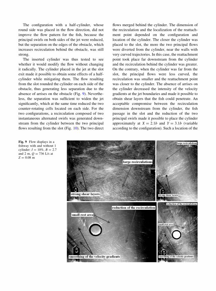
The inserted cylinder was thus tested to see
whether it would modify the flow without changing
it radically. The cylinder placed in the jet at the slot
exit made it possible to obtain some effects of a half-
cylinder while mitigating them. The flow resulting
from the slot rounded the cylinder on each side of the
obstacle, thus generating less separation due to the
absence of arrises on the obstacle (Fig. 9). Neverthe-
less, the separation was sufficient to widen the jet
significantly, which at the same time reduced the two
counter-rotating cells located on each side. For the
two configurations, a recirculation composed of two
instantaneous alternated swirls was generated down-
stream from the cylinder between the two principal
flows resulting from the slot (Fig. 10). The two direct
flows merged behind the cylinder. The dimension of
the recirculation and the localization of the reattach-
ment point depended on the configuration and
location of the cylinder. The closer the cylinder was
placed to the slot, the more the two principal flows
were diverted from the cylinder, near the walls with
very curved trajectories. In this case, the reattachment
point took place far downstream from the cylinder
and the recirculation behind the cylinder was greater.
On the contrary, when the cylinder was far from the
slot, the principal flows were less curved, the
recirculation was smaller and the reattachment point
was closer to the cylinder. The absence of arrises on
the cylinder decreased the intensity of the velocity
gradients at the jet boundaries and made it possible to
obtain shear layers that the fish could penetrate. An
acceptable compromise between the recirculation
dimension downstream from the cylinder, the fish
passage in the slot and the reduction of the two
principal swirls made it possible to place the cylinder
approximately at X = 2.1b and Y = 3.1b (variable
according to the configuration). Such a location of the
Fig. 9 Flow displays in a
fishway with and without 1
cylinder: I = 10%, B = 2.7
and 2 m, Q = 736 L/s at
Z = 0.08 m

cylinder significantly influenced the flow pattern (by
deviating the jet and shear layer and reducing the
recirculation currents) while allowing passage of the
large fish.
A last test with two cylinders was achieved for the
two configurations (Fig. 11). The first was placed at
the slot exit in order to widen the jet and to reduce the
two counter-rotating contra-rotating cells on each
side. The second cylinder was placed downstream
from the first, slightly shifted in the pool according to
the configuration, in order to break the direct flow
resulting from the deviation of the first cylinder. This
configuration made it possible to reduce the recircu-
lation located between the lateral deflectors.
However, this recirculation became more intense
and the rotation rate was stronger than for the
configuration with only one cylinder.
Discussion and conclusion
The flow for various configurations of vertical slot
fishways was finally limited to two principal topo-
logical models according to the length/width ratio of
the pool. The first, which occurred for L/B = 10/9,
was composed of two large recirculation areas
located on each side of the jet leaving the slot. The
second occurred when the L/B ratio was lower than
3/2. The large recirculation area was then divided, by
the jet hitting the side wall, into two swirling cells,
one of which was located at the upstream corner of
the pool and the other along the central baffle. A third
swirl then occupied the convex part of the jet.
Depending on the channel slope, the intermediate
pool widths generated one or other of the models. For
these two topologies, the flow within the pool was
fairly two dimensional as the fish, which swim up the
vertical slot, encounter the same characteristics at any
Fig. 10 Flow patterns in a
fishway with and without 1
cylinder: I = 10%, B = 2.7
and 2 m, Q = 736 L/s
Fig. 11 Flow displays in a fishway with 2 cylinders: I = 10%,
B = 2.7 m, Q = 736 L/s at Z = 0.08 m

depth of the flow from the bottom to the water
surface. Moreover, a discharge variation caused a
variation of the water depth in the fishway without
modifying the flow patterns. Velocities and turbulent
energies increased with the channel slope.
A strong link was found between the calculated,
volumetric dissipated power and the mean kinetic
energy of velocity fluctuations measured in the pools.
They both increased when the fishway slope
increased, while remained independent of the flow
discharge in the pools. This overall finding was
completed by a spatial analysis of the turbulent
energy. The places where the high energy was
measured are the sites of the largest velocity fluctu-
ations in the fishway. A more refined analysis of
turbulent kinetic energy will be made to distinguish
between the values in high-velocity areas, where fish
have to pass, and values in low-mean velocity areas,
which are necessary to allow small species to rest.
Visual observations made in large vertical slot fish
passes equipped with viewing windows showed that
certain small species can remain trapped for a very
long time in the large recirculation zones in the pools.
All these areas, which in principle are designed to be
resting areas, become in fact traps for small fish.The
drastic increase of transit times in each pool can delay
the clearing of the fish pass, particularly in the case of
a facility composed of numerous pools. Such delays
in pools were observed during a recent study of the
behaviour of percid species (Zingel asper L.) in
model fish passes (Gomes et al., 2005). Such exam-
ples of fish being disoriented have been observed in
Denil fish passes. An increase in the sizes of the
baffles results in an increase in the size of the
helicoidal currents; if the eddies become too large in
relation to the fish, then the fish will tend to orient
themselves in relation to the local components of the
velocity and bump into baffles. This may diminish the
efficiency of the facility (Larinier et al., 2002).
A first solution for small species would consist of
reducing both the drop between pools and the
dimensions of the pools, so as to reduce the
maximum velocities, turbulence and size of recircu-
lation areas. The main drawback is that the width of
slots and length of pools can become inadequate for
large species and it would thus be advisable to install
two fish passes (one for small and one for large fish)
on the same obstruction. On existing facilities, the
most realistic and economical solution is to adapt the
internal flow in the pools. Considering that it is not
easy to reduce the drop between pools, the only way
this can be done is to reduce the sizes of recirculating
areas and to attenuate the obstacle of the strong shear
layers at the jet boundaries.
An obstacle placed in specific zones of the flow
can control the flow and might be a way of
facilitating the migration of small species by limiting
the number and size of trap zones and decreasing the
turbulence. A cylinder of dimension equal to the slot
width b, judiciously inserted at the slot exit, modified
the flow and limited obstacle zones within the pools
of vertical slot fishways. Indeed, the flow resulting
from the slot turned around the cylinder on each side
of the obstacle. The separation was sufficient to
widen the jet significantly, which in turn reduced the
two counter-rotating cells located on each side. A
small recirculation zone, composed of two instanta-
neous alternated swirls, was generated downstream
from the cylinder between the two principal flows
leaving the slot and reattaching behind the obstacle.
Because of the risk of disorientation if the eddies
become too large in relation to the fish, the reduction
of the two large recirculating structures by the
insertion of a cylinder made it possible to decrease
the trap zones, where the fish could remain blocked
for a very long time. The recirculating cell generated
behind the obstacle did not create any problems for
the fish because it was small and provided a rest area
when they ascend the fishway. The cylinder
decreased both the velocities near the slot and
attenuated the velocity gradients at the jet boundaries.
The smoothing of these intense shear layers made it
possible to limit the obstacle zones and to facilitate
the penetration of fish, which had been trapped in the
large recirculation currents in the jet. The passage
through the slots by the small species became easier
due to reduction in velocity gradients, which were
better suited to their swimming abilities.
A study with various fish species (migrating
species such as brown trout and riverine species such
as gudgeon, roach, club, bleak and common bitter-
ling) has been undertaken to validate this type of
adaptation of vertical slot fishway and to check its
effectiveness on fish behaviour. The first results,
which still have to be confirmed and expanded by
other experiments, tend to verify the contribution of a
cylinder in the pool for small fish and to demonstrate
the potential of changing the geometry in this way.

Acknowledgements This work was undertaken in the
Laboratoire d’Etudes Aerodynmiques (LEA) at the
University of Poitiers. Financial support was provided by the
Voies Navigables de France1 and the Direction Regionale de
l’Environnement. Our thanks as well to all laboratory
technicians for their help in installing the facility and during
the experiments.
References
Gomes, P., S. Vighetti & M. Larinier, 2005. Etude pour la
conception de passes a poissons adaptees a l’Apron.
Rapport GHAAPPE RA05.05: 1–45.
Larinier, M., F. Travade & J. P. Porcher, 2002. Fishways:
Biological basis, design criteria and monitoring. Bulletin
Francais de la Peche et de la Pisculture 364: 1–208.
Pena Mosquera, L., L. Cea & J. Puertas, 2004. An experimental
analysis in vertical slot fishways. Proceedings of the Fifth
International Symposium on Ecohydraulics, 2–3 Septem-
ber, Madrid: 881–888.
Puertas, J., L. Pena Mosquera & T. Teijeiro, 2004. An exper-
imental approach to the hydraulics of vertical slot
fishways. Journal of Hydraulic Engineering 130: 10–23.
Rajaratnam, N., C. Katopodis & G. Van Der Vinne, 1986.
Hydraulics of vertical slot fishways. Journal of Hydraulic
Engineering 112: 909–927.
Rajaratnam, N., C. Katopodis & S. Solanki, 1992. New designs
for vertical slot fishways. Journal of Hydraulic Engi-
neering 19: 402–414.
Wu, S., N. Rajaratnam & C. Katopodis, 1999. Structure of flow
in vertical slot fishway. Journal of Hydraulic Engineering
125: 351–360.
1 NdT Navigable French waterways