torque equation of a dc motor - gpcet.ac.in · web viewthe working of dc motor is based on the...
TRANSCRIPT

G .PULLAIAH COLLEGE OF ENGINEERING AND TECHNOLOGYDepartment OF EEE
UNIT-2DC Machines
BASIC TERMS AND DEFINITIONS:
Term DescriptionGenerator An A dc generator is an electrical machine which converts
mechanical energy into direct current electricity. This energy conversion is based on the principle of production of dynamically induced emf.
Faraday's first law First Law of Faraday's Electromagnetic Induction state that whenever a conductor are placed in a varying magnetic field emf are induced which is called induced emf, if the conductor circuit are closed current are also induced which is called induced current.
Faraday's second law Faraday's second law of electromagnetic induction states that, the magnitude of induced emf is equal to the rate of change of flux linkages with the coil. The flux linkages is the product of number of turns and the flux associated with the coil.
Fleming's Left Hand Rule
According to Fleming's left hand rule, if the thumb, fore-finger and middle finger of the left hand are stretched to be perpendicular to each other as shown in the illustration at left, and if the fore finger represents the direction of magnetic field, the middle finger represents the direction of current, then the thumb represents the direction of force. Fleming's left hand rule is applicable for motors.
Fleming's Right Hand Rule
According to the Fleming's right hand rule, the thumb, fore finger and middle finger of the right hand are stretched to be perpendicular to each other as shown in the illustration at right, and if the thumb represents the direction of the movement of conductor, fore-finger represents direction of the magnetic field, then the middle finger represents direction of the induced current.
Stator The stationary portion of an electric generator or motor Rotor Rotating member of a machineMagnetic Field System The Magnetic Field System is the stationary or fixed part of the
machine. It produces the main magnetic fluxYoke The outer hollow cylindrical frame to which main poles and
inter-poles are fixed and by means of which the machine is fixed to the foundation is known as Yoke.
Pole Core and Pole Shoes
The Pole Core and Pole Shoes are fixed to the magnetic frame or yoke by bolts. Since the poles, project inwards they are called salient poles

Field or Exciting Coils Each pole core has one or more field coils (windings) placed over it to produce a magnetic field.
Armature of DC Generator
The rotating part of the DC machine or a DC Generator is called the Armature.
Armature Core The armature core of DC Generator is cylindrical in shape and keyed to the rotating shaft
Armature Winding Armature winding is a place where conversion of power takes place. In the case of a DC Generator here, mechanical power is converted into electrical power.
Lap Winding In lap winding, the conductors are connected in such a way that the number of parallel paths are equal to the number of poles
Wave WindingIn wave winding, the conductors are so connected that they are divided into two parallel paths irrespective of the number of poles of the machine
Commutator It converts the induced alternating current in the armature conductor into unidirectional current in the external load circuit in DC Generator action
Brushes Carbon brushes are placed or mounted on the commutator and with the help of two or more carbon brushes current is collected from the armature winding.
End Housings End housings are attached to the ends of the Mainframe and provide support to the bearings.
Bearings The ball or roller bearings are fitted in the end housings. The function of the bearings is to reduce friction between the rotating and stationary parts of the machine.
Shaft The shaft is made of mild steel with a maximum breaking strength. The shaft is used to transfer mechanical power from or to the machine
winding material wound or coiled about an object
Excitation An electric generator or electric motor consists of a rotor spinning in a magnetic field. ... The process of generating a magnetic field by means of an electric current is called excitation.
Self-excitation Self-excitation is made use of most often in DC generators. When a self-excitedgenerator is started, the initial current in the field winding is produced by the electromotive force (emf) induced in the armature winding by the residual magnetic field of the main poles.
separately-excitation A separately-excited dc generator is a dc generator whose field magnet winding current is supplied by an external dc voltage source. For comparison, a self-excited dc generator is a dc generator whose field magnet winding is supplied by current from the output of the generator itself.
Critical field Resistance
Critical field resistance is a term that is associated with a shunt DC generator. ... The critical field resistance is defined as the maximum field circuit resistance (for a given speed) with which the shunt generator would excite.

Critical Speed Critical field resistance is a term that is associated with a shunt DC generator. ... The shunt generator will build up voltage only if field circuit resistance is less than critical field resistance. It is a Tangent to the Open Circuit Characteristics of the Generator(at a given speed).
Shunt Generator A shunt generator is a type of direct current electric generator in which field winding and armature winding are connected in parallel, and in which the armature supplies both the load current and the field current.
Series Generator In which the armature winding is connected in series with the field winding so that the field current flows through the load as well as the field winding
Compound Generator It has two field findings namely Rsh and Rse. They are basically shunt winding (Rsh) and series winding (Rse). Compound generator is of two types – 1) Short shunt and 2) Long shunt
Short shunt Here the shunt field winding is wired parallel to armature and series field winding is connected in series to the load
Long shunt Here the shunt field winding is parallel to both armature and series field winding
Equalizer Ring An equalizer ring has a low resistance conductor wire, which connects together the points in the armature winding which should be at the same potentials. The function of equalizer rings are- To cause the circulating current to flow within the armature winding itself, without letting them pass through the brushes.
Excitation An electric generator or electric motor consists of a rotor spinning in a magnetic field. ... The process of generating a magnetic field by means of an electric current is called excitation.
Self-excitation Self-excitation is made use of most often in DC generators. When a self-excitedgenerator is started, the initial current in the field winding is produced by the electromotive force (emf) induced in the armature winding by the residual magnetic field of the main poles.
separately-excitation A separately-excited dc generator is a dc generator whose field magnet winding current is supplied by an external dc voltage source. For comparison, a self-excited dc generator is a dc generator whose field magnet winding is supplied by current from the output of the generator itself.
Critical field Resistance
Critical field resistance is a term that is associated with a shunt DC generator. ... The critical field resistance is defined as the maximum field circuit resistance (for a given speed) with which the shunt generator would excite.
Critical Speed Critical field resistance is a term that is associated with a shunt DC generator. ... The shunt generator will build up voltage only if field circuit resistance is less than critical field resistance. It is a Tangent to the Open Circuit Characteristics of the Generator(at a given speed).
Shunt Generator A shunt generator is a type of direct current electric generator in

which field winding and armature winding are connected in parallel, and in which the armature supplies both the load current and the field current.
Series Generator In which the armature winding is connected in series with the field winding so that the field current flows through the load as well as the field winding
Compound Generator It has two field findings namely Rsh and Rse. They are basically shunt winding (Rsh) and series winding (Rse). Compound generator is of two types – 1) Short shunt and 2) Long shunt
Short shunt Here the shunt field winding is wired parallel to armature and series field winding is connected in series to the load
Long shunt Here the shunt field winding is parallel to both armature and series field winding
Equalizer Ring An equalizer ring has a low resistance conductor wire, which connects together the points in the armature winding which should be at the same potentials. The function of equalizer rings are- To cause the circulating current to flow within the armature winding itself, without letting them pass through the brushes.
CONCEPTS:
Construction of a DC GeneratorA DC Generator is an electrical device which converts mechanical energy into electrical energy. It mainly consists of three main parts, i.e. Magnetic field system, Armature and Commutator and Brush gear. The other parts of a DC Generator are Magnetic frame and Yoke, Pole Core and Pole Shoes, Field or Exciting coils, Armature Core and Windings, Brushes, End housings, Bearings and Shafts.The diagram of the main parts of a 4 pole DC Generator or DC Machine is shown below.

CONTENTS:
Magnetic Field System of DC GeneratorThe Magnetic Field System is the stationary or fixed part of the machine. It produces the main magnetic flux. The magnetic field system consists of Mainframe or Yoke, Pole core and Pole shoes and Field or Exciting coils. These various parts of DC Generator are described below in detail.
Magnetic Frame and Yoke The outer hollow cylindrical frame to which main poles and inter-poles are fixed and by means of which the machine is fixed to the foundation is known as Yoke. It is made of cast steel or rolled steel for the large machines and for the smaller size machine the yoke is generally made of cast iron.
The two main purposes of the yoke are as follows:-It supports the pole cores and provides mechanical protection to the inner parts of the machines.It provides a low reluctance path for the magnetic flux.
Pole Core and Pole ShoesThe Pole Core and Pole Shoes are fixed to the magnetic frame or yoke by bolts. Since the poles, project inwards they are called salient poles. Each pole core has a curved surface. Usually, the pole core and shoes are made of thin cast steel or wrought iron laminations which are riveted together under hydraulic pressure. The poles are laminated to reduce the Eddy Current loss.The figure of pole core and pole shoe are shown below.

Field or Exciting CoilsEach pole core has one or more field coils (windings) placed over it to produce a magnetic field. The enamelled copper wire is used for the construction of field or exciting coils. The coils are wound on the former and then placed around the pole core.
When direct current passes through the field winding, it magnetizes the poles, which in turns produces the flux. The field coils of all the poles are connected in series in such a way that when current flows through them, the adjacent poles attain opposite polarity.Armature of DC GeneratorThe rotating part of the DC machine or a DC Generator is called the Armature.The armature consists of a shaft upon which a laminated cylinder, called Amature Core is placed.
Armature CoreThe armature core of DC Generator is cylindrical in shape and keyed to the rotating shaft. At the outer periphery of the armature has grooves or slots which accommodate the armature winding as shown in the figure below.
The armature core of a DC generator or machine serves the following purposes. It houses the conductors in the slots. It provides an easy path for the magnetic flux.
As the armature is a rotating part of the DC Generator or machine, the reversal of flux takes place in the core, hence hysteresis losses are produced. The silicon steel material is used for the construction of the core to reduce the hysteresis losses.The rotating armature cuts the magnetic field, due to which an emf is induced in it. This emf circulates the eddy current which results in Eddy Current loss. Thus to reduce the loss the armature core is laminated with a stamping of about 0.3 to 0.5 mm thickness. Each lamination is insulated from

the other by a coating of varnish.
Armature WindingThe insulated conductors are placed in the slots of the armature core. The conductors are wedged, and bands of steel wire wound around the core and are suitably connected. This arrangement of conductors is called Armature Winding. The armature winding is the heart of the DC Machine.Armature winding is a place where conversion of power takes place. In the case of a DC Generator here, mechanical power is converted into electrical power. On the basis of connections, the windings are classified into two types named as Lap Winding and Wave Winding.
Lap WindingIn lap winding, the conductors are connected in such a way that the number of parallel paths are equal to the number of poles. Thus, if a machine has P poles and Z armature conductors, then there will be P parallel paths, each path will have Z/P conductors connected in series.In lap winding, the number of brushes is equal to the number of parallel paths. Out of which half the brushes are positive and the remaining half are negative.
Wave WindingIn wave winding, the conductors are so connected that they are divided into two parallel paths irrespective of the number of poles of the machine. Thus, if the machine has Z armature conductors, there will be only two parallel paths each having Z/2 conductors in series. In this case number of brushes is equal to two, i.e. number of parallel paths.
Commutator in DC Generator
The commutator, which rotates with the armature, is cylindrical in shape and is made from a number of wedge-shaped hard drawn copper bars or segments insulated from each other and from the shaft. The segments form a ring around the shaft of the armature. Each commutator segment is connected to the ends of the armature coils.
BrushesCarbon brushes are placed or mounted on the commutator and with the help of two or more carbon brushes current is collected from the armature winding. Each brush is supported in a metal box called a brush box or brush holder. The brushes are pressed upon the commutator and form the connecting link between the armature winding and the external circuit.The pressure exerted by the brushes on the commutator can be adjusted and is maintained at a constant value by means of springs. With the help of the brushes the current which is produced on the windings, is passed on to the commutator and then to the external circuit.
End HousingsEnd housings are attached to the ends of the Mainframe and provide support to the bearings. The front housings support the bearing and the brush assemblies where as the rear housings usually support the

bearings only.BearingsThe ball or roller bearings are fitted in the end housings. The function of the bearings is to reduce friction between the rotating and stationary parts of the machine. Mostly high carbon steel is used for the construction of bearings as it is very hard material.ShaftThe shaft is made of mild steel with a maximum breaking strength. The shaft is used to transfer mechanical power from or to the machine. The rotating parts like armature core, commutator, cooling fans, etc. are keyed to the shaft.
Working Principle of A DC Generator
According to Faraday’s laws of electromagnetic induction, whenever a conductor is placed in a varying magnetic field (OR a conductor is moved in a magnetic field), an emf (electromotive force) gets induced in the conductor. The magnitude of induced emf can be calculated from the emf equation of dc generator. If the conductor is provided with a closed path, the induced current will circulate within the path. In a DC generator, field coils produce an electromagnetic field and the armature conductors are rotated into the field. Thus, an electromagnetically induced emf is generated in the armature conductors. The direction of induced current is given by Fleming’s right hand rule.
According to Fleming’s right hand rule, the direction of induced current changes whenever the direction of motion of the conductor changes. Let’s consider an armature rotating clockwise and a conductor at the left is moving upward. When the armature completes a half rotation, the direction of motion of that particular conductor will be reversed to downward. Hence, the direction of current in every armature conductor will be alternating. If you look at the above figure, you will know how the direction of the induced current is alternating in an armature conductor. But with a split ring commutator, connections of the armature conductors also get reversed when the current reversal occurs. And therefore, we get unidirectional current at the terminals.
Types of armature winding: Armature conductors are connected in a specific manner called as armature winding and according to the way of connecting the conductors; armature winding is divided into two types. Lap winding: In this case, if connection is started from conductor in slot 1 then the connections overlap each other as winding proceeds, till starting point is reached again. There is overlapping of coils while proceeding. Due to such connection, the total number of conductors get divided into ‘P’ number of parallel paths, where P = number of poles in the machine. Large number of parallel paths indicates high current capacity of machine hence lap winding is pertained for high current rating generators. Wave winding: In this type, winding always travels ahead avoiding over lapping. It travels like a progressive wave hence called wave winding. Both coils starting from slot 1 and slot 2 are progressing in wave fashion. Due to this type of connection, the total number of conductors get divided into two number of parallel paths always, irrespective of number of poles of

machine. As number of parallel paths is less, it is preferable for low current, high voltage capacity generators.
EMF equation of a generator
The derivation of EMF equation for DC generator has two parts:1. Induced EMF of one conductor2. Induced EMF of the generator
Derivation for Induced EMF of One Armature ConductorFor one revolution of the conductor, Let, Φ = Flux produced by each pole in weber (Wb) and P = number of poles in the DC generator.therefore, Total flux produced by all the poles=P*Ф And, Time taken to complete one revolution=60/N Where, N = speed of the armature conductor in rpm. Now, according to Faraday’s law of induction, the induced emf of the armature conductor is denoted by “e” which is equal to rate of cutting the flux.
Lap winding:Lap winding is the winding in which successive coils overlap each other. It is named "Lap" winding because it doubles or laps back with its succeeding coils.
WAVE Winding:In this winding the end of one coil is connected to the starting of another coil of the same polarity as that of the first coil.
Types of DC Generator – Separately Excited and Self Excited
The figure of self-excited DC Generator is shown below. The DC generator converts the electrical power into electrical power. The magnetic flux in a DC machine is produced by the field coils carrying current. The circulating current in the field windings produces a magnetic flux, and the phenomenon is known as Excitation. DC Generator is classified according to the methods of their field excitation.

Separately Excited DC Generator
A DC generators whose field winding or coil is energised by a separate or external DC source is called a separately excited DC Generator. The flux produced by the poles depends upon the field current with the unsaturated region of magnetic material of the poles. i.e. flux is directly proportional to the field current. But in the saturated region, the flux remains constant.
Self Excited DC Generator
Self-excited DC Generator is a device, in which the current to the field winding is supplied by the generator itself. In self-excited DC generator, the field coils mat be connected in parallel with the armature in the series, or it may be connected partly in series and partly in parallel with the armature windings.
The self-excited DC Generator is further classified as
Shunt Wound Generator
In a shunt wound generator, the field winding is connected across the armature winding forming a parallel or shunt circuit. Therefore, full terminal voltage is applied across it. A very small field current Ish, flows through it because this winding has many turns of fine wire having very high resistance Rsh of the order of 100 ohms.
The connection diagram of shunt wound generator is shown below.

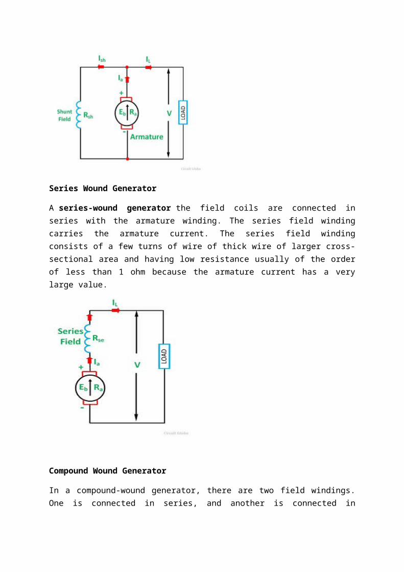
Series Wound Generator
A series-wound generator the field coils are connected in series with the armature winding. The series field winding carries the armature current. The series field winding consists of a few turns of wire of thick wire of larger cross-sectional area and having low resistance usually of the order of less than 1 ohm because the armature current has a very large value.
Compound Wound Generator
In a compound-wound generator, there are two field windings. One is connected in series, and another is connected in parallel with the armature windings. There are two types of compound-wound generator.
Long shunt compound-wound generator
Short shunt compound-wound generator
Long Shunt Compound Wound Generator

In a long shunt wound generator, the shunt field winding is parallel with both armature and series field winding. The connection diagram of long shunt wound generator is shown below.
.
Short Shunt Compound Wound Generator
In a Short Shunt Compound Wound Generator, the shunt field winding is connected in parallel with the armature winding only. The connection diagram of short shunt wound generator is shown below.
Characteristics Of DC Generators
Generally, following three characteristics of DC generators are taken into considerations: (i) Open Circuit Characteristic (O.C.C.), (ii) Internal or Total Characteristic and (iii) External Characteristic. These characteristics of DC generators are explained below.
1. Open Circuit Characteristic (O.C.C.) (E0/If)
Open circuit characteristic is also known as magnetic characteristic or no-load saturation characteristic. This characteristic shows the relation between generated emf at no load (E0) and the field current (If) at a given fixed speed. The O.C.C. curve is just the magnetization

curve and it is practically similar for all type of generators. The data for O.C.C. curve is obtained by operating the generator at no load and keeping a constant speed. Field current is gradually increased and the corresponding terminal voltage is recorded. The connection arrangement to obtain O.C.C. curve is as shown in the figure below. For shunt or series excited generators, the field winding is disconnected from the machine and connected across an external supply.
Now, from the emf equation of dc generator, we know that Eg = kɸ. Hence, the generated emf should be directly proportional to field flux (and hence, also directly proportional to the field current). However, even when the field current is zero, some amount of emf is generated (represented by OA in the figure below). This initially induced emf is due to the fact that there exists some residual magnetism in the field poles. Due to the residual magnetism, a small initial emf is induced in the armature. This initially induced emf aids the existing residual flux, and hence, increasing the overall field flux. This consequently increases the induced emf. Thus, O.C.C. follows a straight line. However, as the flux density increases, the poles get saturated and the ɸ becomes practically constant. Thus, even we increase the If further, ɸ remains constant and hence, Eg also remains constant. Hence, the O.C.C. curve looks like the B-H characteristic.
2. Internal Or Total Characteristic (E/Ia)
An internal characteristic curve shows the relation between the on-load generated emf (Eg) and the armature current (Ia). The on-load generated emf Eg is always less than E0 due to the armature reaction. Eg can be determined by subtracting the drop due to demagnetizing

effect of armature reaction from no-load voltage E0. Therefore, internal characteristic curve lies below the O.C.C. curve.
3. External Characteristic (V/IL)
An external characteristic curve shows the relation between terminal voltage (V) and the load current (IL). Terminal voltage V is less than the generated emf Eg due to voltage drop in the armature circuit. Therefore, external characteristic curve lies below the internal characteristic curve. External characteristics are very important to determine the suitability of a generator for a given purpose. Therefore, this type of characteristic is sometimes also called as performance characteristic or load characteristic.
Characteristics Of Separately Excited DC Generator
If there is no armature reaction and armature voltage drop, the voltage will remain constant for any load current. Thus, the straight line AB in above figure represents the no-load voltage vs. load current IL. Due to the demagnetizing effect of armature reaction, the on-load generated emf is less than the no-load voltage. The curve AC represents the on-load generated emf Eg vs. load current ILi.e. internal characteristic (as Ia = IL for a separately excited dc generator). Also, the terminal voltage is lesser due to ohmic drop occurring in the armature and brushes. The curve AD represents the terminal voltage vs. load current i.e. external characteristic.
Characteristics Of DC Shunt Generator
To determine the internal and external load characteristics of a DC shunt generator the machine is allowed to build up its voltage before applying any external load. To build up voltage of a shunt generator, the generator is driven at the rated speed by a prime mover. Initial voltage is induced due to residual magnetism in the field poles. The generator builds up its voltage as explained by the O.C.C. curve. When the generator has built up the voltage, it is gradually loaded with resistive load and readings are taken at suitable intervals. Connection arrangement is as shown in the figure below.
Unlike, separately excited DC generator, here, IL≠Ia. For a shunt generator, Ia=IL+If. Hence, the internal characteristic can be easily transmitted to Eg vs. IL by subtracting the correct value of Iffrom Ia.
During a normal running condition, when load resistance is decreased, the load current increases. But, as we go on decreasing the load resistance, terminal voltage also falls. So, load resistance can be decreased up to a certain limit, after which the terminal voltage drastically decreases due to excessive armature reaction at very high armature current and increased I2R losses. Hence, beyond this limit any further decrease in load resistance results in decreasing load current. Consequently, the external characteristic curve turns back as shown by dotted line in the above figure.
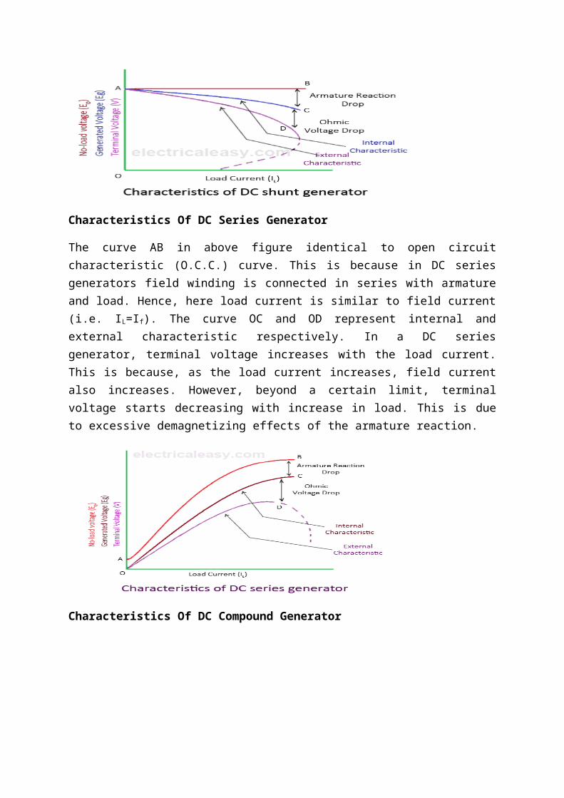
Characteristics Of DC Series Generator
The curve AB in above figure identical to open circuit characteristic (O.C.C.) curve. This is because in DC series generators field winding is connected in series with armature and load. Hence, here load current is similar to field current (i.e. IL=If). The curve OC and OD represent internal and external characteristic respectively. In a DC series generator, terminal voltage increases with the load current. This is because, as the load current increases, field current also increases. However, beyond a certain limit, terminal voltage starts decreasing with increase in load. This is due to excessive demagnetizing effects of the armature reaction.

Characteristics Of DC Compound Generator
The above figure shows the external characteristics of DC compound generators. If series winding amp-turns are adjusted so that, increase in load current causes increase in terminal voltage then the generator is called to be over compounded. The external characteristic for over compounded generator is shown by the curve AB in above figure.If series winding amp-turns are adjusted so that, the terminal voltage remains constant even the load current is increased, then the generator is called to be flat compounded. The external characteristic for a flat compounded generator is shown by the curve AC.If the series winding has lesser number of turns than that would be required to be flat compounded, then the generator is called to be under compounded. The external characteristics for an under compounded generator are shown by the curve AD.
Working Principle of DC Motor
An Electric DC motor is a machine which converts electric energy into mechanical energy. The working of DC motor is based on the principle that when a current-carrying conductor is placed in a magnetic field, it experiences a mechanical force.

The direction of mechanical force is given by Fleming’s Left-hand Rule and its magnitude is given by F = BIL Newton.
There is no basic difference in the construction of a DC generator and a DC motor. In fact, the same d.c. machine can be used interchangeably as a generator or as a motor. Like generators DC motors are also classified in to shunt-wound, series-wound and compound-wound.DC motors are seldom used in ordinary applications because all electric supply companies furnish alternating current. However, for special applications such as in steel mills, mines and electric trains, it is advantageous to convert alternating current into direct current in order to use dc motors. The reason is that speed/torque characteristics of d.c. motors are much more superior to that of a.c. motors. Therefore, it is not surprising to note that for industrial drives, d.c. motors are as popular as 3-phase induction motors.
DC Motor PrincipleA machine that converts DC power into mechanical power is known as a DC motor.
Its operation is based on the principle that when a current carrying conductor is placed in a magnetic field, the conductor experiences a mechanical force. The direction of this force is given by Fleming’s left hand rule and magnitude is given by;
F = BIL Newtons

Basically, there is no constructional difference between a DC motor and a DC generator. The same DC machine can be run as a generator or motor.Working of DC MotorConsider a part of a multipolar d.c. motor as shown in Figure below. When the terminals of the motor are connected to an external source of d.c. supply:
1. the field magnets are excited developing alternate N and S poles2. the armature conductors carry currents.
All conductors under N-pole carry currents in one direction while all the conductors under S-pole carry currents in the opposite direction.
Suppose the conductors under N-pole carry currents into the plane of the paper and those under S-pole carry currents out of the plane of the paper as shown in Figure.
Since each armature conductor is carrying current and is placed in the magnetic field, mechanical force acts on it.
On applying Fleming’s left hand rule, it is clear that force on each conductor is tending to rotate the armature in anticlockwise direction. All these forces add together to produce a driving torque which sets the armature rotating.When the conductor moves from one side of a brush to the other, the current in that conductor is reversed and at the same time it comes under the influence of next pole which is of opposite polarity. Consequently, the direction of force on the conductor remains the same.It should be noted that the function of a commutator in the motor is the same as in a generator. By reversing current in each conductor as it passes from one pole to another, it helps to develop a continuous and unidirectional torque.
Torque Equation Of A DC Motor
When armature conductors of a DC motor carry current in the presence of stator field flux, a mechanical torque is developed between the armature and the stator. Torque is given by the product of the force and the radius at which this force acts.

Torque T = F × r (N-m) …where, F = force and r = radius of the armatureWork done by this force in once revolution = Force × distance = F × 2πr (where, 2πr = circumference of the armature)Net power developed in the armature = word done / time = (force × circumference × no. of revolutions) / time = (F × 2πr × N) / 60 (Joules per second) But, F × r = T and 2πN/60 = angular velocity ω in radians per second.Net power developed in the armature = P = T × ω (Joules per second)
Armature Torque (Ta)
The power developed in the armature can be given as, Pa = Ta × ω = Ta × 2πN/60The mechanical power developed in the armature is converted from the electrical power,Therefore, mechanical power = electrical power That means, Ta × 2πN/60 = Eb.IaWe know, Eb = PΦNZ / 60ATherefore, Ta × 2πN/60 = (PΦNZ / 60A) × IaRearranging the above equation,Ta = (PZ / 2πA) × Φ.Ia (N-m)The term (PZ / 2πA) is practically constant for a DC machine. Thus, armature torque is directly proportional to the product of the flux and the armature current i.e. Ta ∝ Φ.Ia
Shaft Torque (Tsh)
Due to iron and friction losses in a dc machine, the total developed armature torque is not available at the shaft of the machine. Some torque is lost, and therefore, shaft torque is always less than the armaturetorque.
Shaft torque of a DC motor is given as,Tsh = output in watts / (2πN/60) ....(where, N is speed in RPM)

Swinburne’s TestSwinburne’s Test is an indirect method of testing of DC machines. In this method the losses are measured separately and the efficiency at any desired load is predetermined. Machines are tested for finding out losses, efficiency and temperature rise. For small machines direct loading test is performed. For large shunt machines, indirect methods are used like Swinburne’s or Hopkinson’s test.
Advantages of Swinburne’s Test
The main advantages of the Swinburne’s test are as follows:-
The power required to test a large machine is small. Thus, this method is an economical and convenient method of testing of DC machines.
As the constant loss is known the efficiency can be predetermined at any load.
Disadvantages of Swinburne’s Test
Change in iron loss is not considered at full load from no load. Due to armature reaction flux is distorted at full load and, as a result, iron loss is increased.
As the Swinburne’s test is performed at no load. Commutation on full load cannot be determined whether it is satisfactory or not and whether the temperature rise is within the specified limits or not.
Limitations of Swinburne’s Test
Machines having a constant flux are only eligible for Swinburne’s test. For examples – shunt machines and level compound generators.
Series machines cannot run on light loads, and the value of speed and flux varies greatly. Thus, the Swinburne’s Test are not applicable for series machines
Applications of DC MotorsThe main applications of the three types of direct current motors are given below.
Series Motors
The series DC motors are used where high starting torque is required, and variations in speed are possible. For example – the series motors are used in Traction system, Cranes, air compressors, Vaccum Cleaner, Sewing machine, etc.
Shunt Motors
The shunt motors are used where constant speed is required and starting conditions are not severe. The various applications of DC shunt motor are in Lathe Machines, Centrifugal Pumps, Fans, Blowers, Conveyors, Lifts, Weaving Machine, Spinning machines, etc.
Compound Motors
The compound motors are used where higher starting torque and fairly constant speed is required. The examples of usage of compound motors are in Presses, Shears, Conveyors, Elevators, Rolling Mills, Heavy Planners, etc.
The small DC machines whose ratings are in fractional kilowatt are mainly used as control device such in Techno generators for speed sensing and in Servo motors for positioning and tracking.
Applications of DC GeneratorsThe applications of the various types of DC Generators are as follows:-
Separately Excited DC Generators
Separately excited DC Generators are used in laboratories for testing as they have a wide range of voltage output.
Used as a supply source of DC motors.
Shunt wound Generators
DC shunt wound generators are used for lighting purposes. Used to charge the battery. Providing excitation to the alternators.
Series Wound Generators
DC series wound generators are used in DC locomotives for regenerative braking for providing field excitation current.
Used as a booster in distribution networks. Over compounded cumulative generators are used in lighting and heavy power supply.

Flat compounded generators are used in offices, hotels, homes, schools, etc. Differentially compounded generators are mainly used for arc welding purpose.