toshiba docsis cable modem owner’s manual · pdf file4 congratulations on your purchase!...
TRANSCRIPT
1
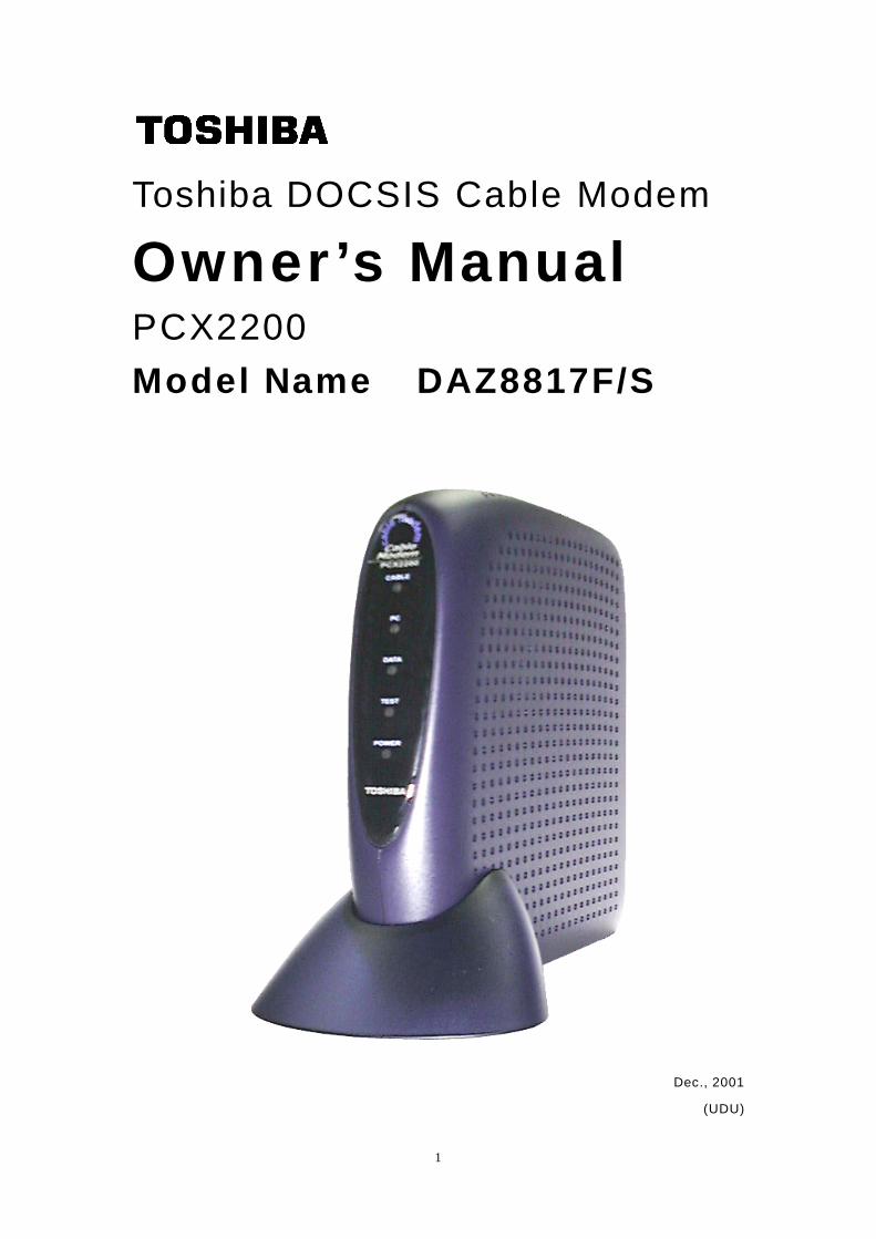
Toshiba DOCSIS Cable Modem
Owner’s Manual PCX2200
Model Name DAZ8817F/S
Dec., 2001
(UDU)
2
Warning:
This product may not be exported outside the US and Canada without US
Department of Commerce, Bureau of Export Administration authorization. Any
export or re-export by the purchaser, directly or indirectly, in contravention of
U.S. Export Administration Regulation is prohibited.
Product and company names listed are trademarks or trade names of their
respective companies.
Copyright 2001, Toshiba Corporation. All rights reserved. This manual may
not be reproduced, in part or in whole, without the permission of Toshiba
Corporation. The content of this manual is subject to change without notice in
the future. Toshiba Corporation assumes no liability for damages resulting
from the use of this product or the information contained in this manual.
3
Table of Contents
Congratulations on Your Purchase 4
Contact Information 4 Support Information 4
Sales Information 4
Web Page 4
Important Rules for Safe Operation 5 Installation 5
Use 6
Service 7
Overview 8 How does a cable modem work? 8
How does a cable modem connect to a computer? 8
What is DOCSIS? 9
Getting Started 10 What’s in the box? 10
Front side LEDs 10
Rear side Connectors 10
Installing USB Drivers 11
Diagnostics 13
How to Use the Stand 14
Specifications 15
Q & A 17
Regulatory 19
Glossary 20
Installing the Cable Modem 22
4
Congratulations on Your Purchase! Your new Toshiba DOCSIS Cable Modem will provide you with high-speed access to the Internet
through your cable TV (CATV) network- accesses at a fraction of the time it takes traditional telephone
modems. In addition, your service will be always connected. Those two features give you the
information you want, when you want it … and your telephone line is kept free.
Contact Information
Support Information
Phone: (949) 583-3223
Fax: (949) 583-3597
e-mail: [email protected]
Sales Information Phone: (949) 461-4840
e-mail: [email protected]
Web Page
http://networks.toshiba.com
5
Important Rules for Safe Operation In addition to the careful attention devoted to quality standards in the manufacture of your Toshiba DOCSIS Cable Modem, safety is a major factor in the design of every product. However, safety is your responsibility, too.
This section lists important information that will help assure your enjoyment and proper use of the Cable
Modem and accessory equipment. Please read them carefully before operating and using your modem.
Installation
Read and Follow Instructions - You should read all the safety and operating
instructions before operating the modem. Follow all operating instructions.
Retain Instructions - You should save all the safety and operating instructions, for
your future reference.
Heed Warnings - Comply with all warnings on the products and in the operating
instructions.
Check Power Sources - Operate this product only from the type of power source
indicated on the product's marking label. If you are not sure of the type of power
supplied to your home, consult your dealer or local power company.
Be Careful of Overloading - Do not overload wall outlets or extension cords, as this
can result in a risk of fire or electric shock. Overloaded AC outlets, extension cords,
frayed power cords, damaged or cracked wire insulation, and broken plugs are
dangerous. They may result in a shock or fire hazard. Periodically examine the cord,
and, if its appearance indicates damage or deteriorated insulation, have it replaced by
your service technician.
Protect Power Cords - Route power supply cords so that they are not likely to be
walked on or pinched by items placed upon or against them.
Pay particular attention to cords where they are attached to plugs and convenience
receptacles, and examine the point where they exit from the product.
Check Ventilation - Slots and openings in the enclosure are provided for ventilation to
ensure reliable operation of the product and to protect it from overheating. Do not
block or cover these openings. Never block these openings by placing the product on
a bed, sofa, rug, or other similar surface. Never place this product near or over a
radiator or heat register, or any other heat source (including amplifiers). Do not place
this product in a built-in installation, such as a bookcase or equipment rack, unless
you provide proper ventilation.
Do Not Use Accessories - Do not use attachments, unless they are recommended
by Toshiba, as they may cause electrical or fire hazards.
Use the Recommended AC Adaptor - You must use the Adaptor that comes with
your Toshiba Cable Modem.
6
Do Not Use Near Water - Do not use this product near water - for example, near a
bath tub, sink or laundry tub, in a wet basement or near a swimming pool, and the like.
Do Not Place Near High Temperature Source - for example near a steamer, Kitchen
range fire, and the like.
Use Caution in Mounting This Product - Do not place this product on an unstable
surface or support. The product may fall, causing serious injury to a child or adult, as
well as serious damage to the product.
Use Care in Moving Product-and-Cart Combinations - Quick stops, excessive,
force and uneven surfaces may cause the product-and-cart combination to overturn.
Ground the Cable Systems – Be sure that the outside cable system is grounded, so
as to provide some protection against voltage surges and built-up static charges.
Section 810 of the national Electric Code, ANSI/NFPA No. 70-1984 (Section 54 of the
Canadian Electrical Code, Part 1) provides information with respect to proper
grounding of the cable systems.
Do not disconnect RF cable from your Cable Modem while the power to your
modem is on.
USE
Unplug Power Before Cleaning - Do not use liquid cleaner or aerosol cleaner. Use a
damp cloth for cleaning.
Keep Objects Out of Openings - Never push objects of any kind into this product
through openings, as they may touch dangerous voltage or "short-out" parts, which
could result in a fire or electric shock. Never spill liquid on the product.
Protect From Lightning - For added protection for this product during a lightning
storm, or when it is left unattended and unused for long periods of time, unplug it from
the wall outlet, and disconnect the cable system. This will prevent damage to the
product due to lightning and power line surges.
Take at least 10 seconds between AC plug off and on.
7
Service
Do Not Remove Covers - Do not attempt to service this product yourself, as opening
or removing covers may expose you to dangerous voltage or other hazards. Refer all
servicing to qualified service personnel.
Unplug this product from the wall outlet carefully, as the AC adaptor may be hot.
Refer Servicing to Qualified Service Personnel Under the Conditions Listed
Below
♦ When the power supply cord or plug is damaged.
♦ If liquid has been spilled or objects have fallen into the product.
♦ If the product has been exposed to rain or water.
♦ If the product does not operate normally by following the operating
instructions.
♦ If the product has been dropped or the cabinet has been damaged.
♦ When the product exhibits a distinct change in performance, such as the
inability to perform basic functions - this indicates a need for service.
Require Safety Check - Upon completion of any service or repairs to this product, ask
the service technician to perform safety checks recommended by service point to
determine that the product is in safe operating condition.
8
Overview The modem provides you with high-speed data communications over the television
cable network by following the widely accepted DOCSIS/MCNS standards being
developed by the Multimedia Cable Network System (MCNS) consortium. Those
standards offer a combination of high performance and interoperability among many of
the cable system operators in North America.
How does a cable modem work?
As you know, digital signals are represented by high and low electrical voltage levels.
And how fast these levels can switch and still be transmitted is determined by the
"bandwidth" of the transmission system. The pair of wires used in a telephone
connection have greatly limited bandwidth, because of their electrical characteristics.
So what we do is connect a device called a modem between the computer output and
the phone line. The modem generates an electrical wave whose strength and phase
change in step with the highs and lows of the computer's digital output. It's because of
the "smoothness" of the resultant signal that a higher data rate can be transmitted.
A cable modem MOdulates and DEModulates electrical signals in the same sense that
the telephone modem does. However, since coaxial cable can carry much higher
wave frequencies, cable modems are far more sophisticated. Their internals can
include a tuner, a bridge, a router, an encryption/decryption device, an SNMP agent,
USB port and an Ethernet hub. Furthermore, none of the activity caused by these
circuits and codes disturbs your regular cable TV reception.
How does a cable modem connect to a computer?
The 10BASE-T Ethernet connection and USB connection used in this Cable Modem
are emerging as the most popular means of connecting a Cable Modem.
The new DOCSIS standard may change this in the future. But for now, a 10BASE-T
Ethernet or USB must be ready in your computer for the Cable Modem to work.
9
What is DOCSIS?
Data Over Cable Service Interface Specifications. DOCSIS defines interface
requirements for cable modems involved in high-speed data distribution over a cable
television network. On November 17, 1997, Cable Television Laboratories, Inc. (Cable
Labs) and its members established a formal path of certification for cable modem
equipment suppliers to obtain an interoperability seal for their products based on the
DOCSIS specification. This certification process provides cable modem equipment
suppliers with a fast, market-oriented method for attaining cable industry
acknowledgment of compliance with DOCSIS.
The seal is meant to provide the purchaser with a way to be confident that the modem
equipment to be purchased is compliant with the specification, and that the equipment
interoperates with DOCSIS products made by other vendors.
10
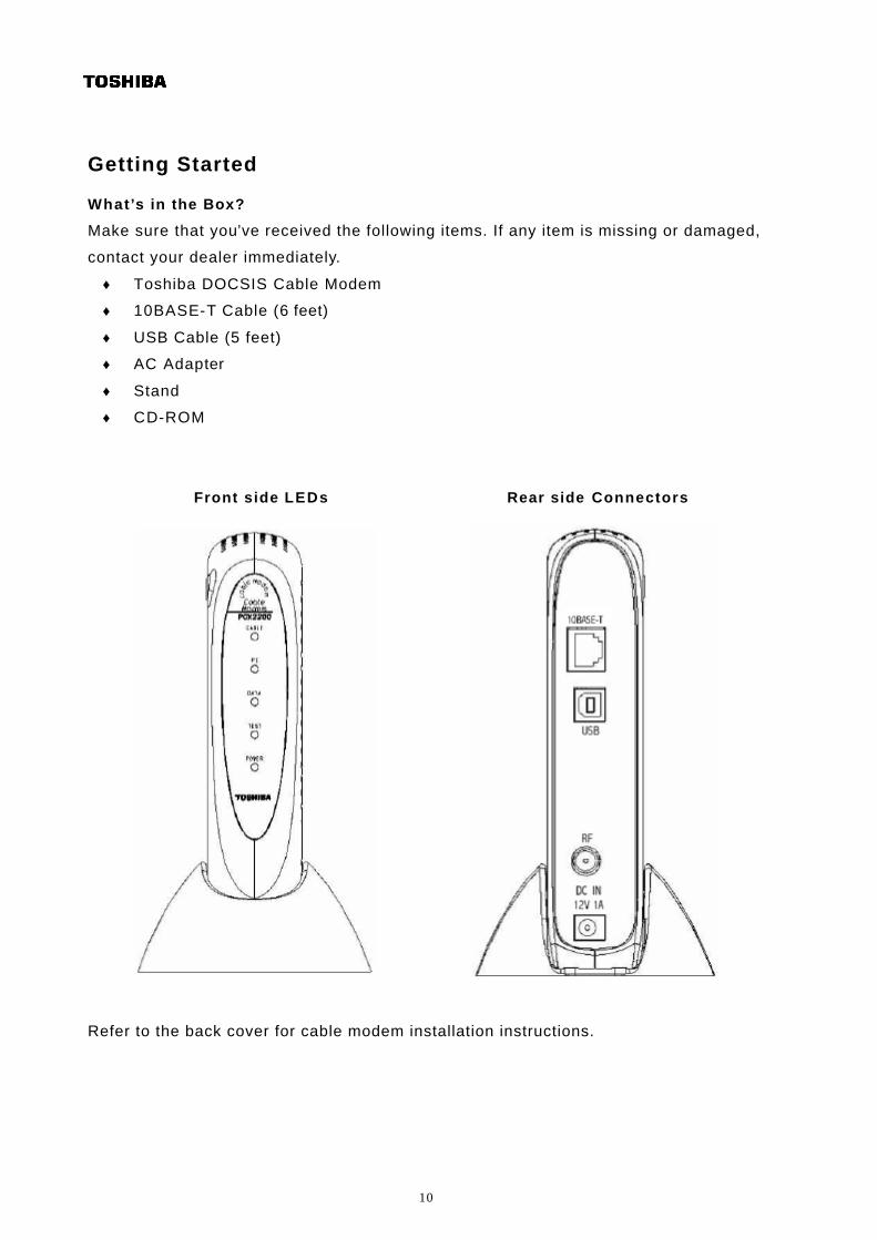
Getting Started
What’s in the Box?
Make sure that you’ve received the following items. If any item is missing or damaged,
contact your dealer immediately.
♦ Toshiba DOCSIS Cable Modem
♦ 10BASE-T Cable (6 feet)
♦ USB Cable (5 feet)
♦ AC Adapter
♦ Stand
♦ CD-ROM
Front side LEDs Rear side Connectors
Refer to the back cover for cable modem installation instructions.
11
Installing USB Drivers
If use the USB interface, connect the cable modem to the PC via the USB,
you must install the "USB Driver" in your PC as follows.
These "USB Drivers" support a PC running Microsoft Windows 98SE,
2000, Me and XP.
Preparation
(1)Confirm the Cable modem ready to transfer data by Front panel LED.
(See "Diagnostics")
(2)Plug the “Type A” end of the USB cable into the USB port of your PC.
Plug the “Type B” end of the USB cable into the back of the Cable Modem.
(3)Insert the USB Drivers CD-ROM into your CD-ROM drive.
Installing USB Drivers
(1)Follow the instructions described in "Preparation" on this page.
After connecting the USB cable, the Add New Hardware Wizard appears.
Click "Next".
(2)Select “Search for the Best Driver for your device" and click “Next”.
(3)Select "CD-ROM drive" and click "Next".
(4)Confirm that the path is correct and click "Next".
Windows should then begin copying the installation drivers.
(5) Click "Finish" to complete the driver installation.
(6)Once this is complete, the process will be repeated for the
“PCX2200…Networking Support”
(7)Once complete, you are ready to surf the internet at warp speed using your new
PCX2200 Cable Modem.
NOTE
If you have trouble installing your new PCX2200 Cable Modem, you may have
inadvertently installed the USB Composite Device Driver that Windows 98SE
automatically loads. To correct this problem, please execute the following on the next
page.
12
USB COMPOSITE DRIVER REMOVAL
(1)Make sure that the USB cable is plugged into your PC. (2)Go to the Start button; choose "Settings" and then "Control Panel".
(3)From inside the "Control Panel" choose "System".
(4)Choose the tab on the top of the screen for "Device Manager".
(5)Click the "+" next to "Universal Serial Bus Controllers".
(6)Click "USB Composite Device" to select it and choose "Remove".
(7)Once the USB Composite Device is removed, restart your PC and follow the
instructions on the previous page.
13
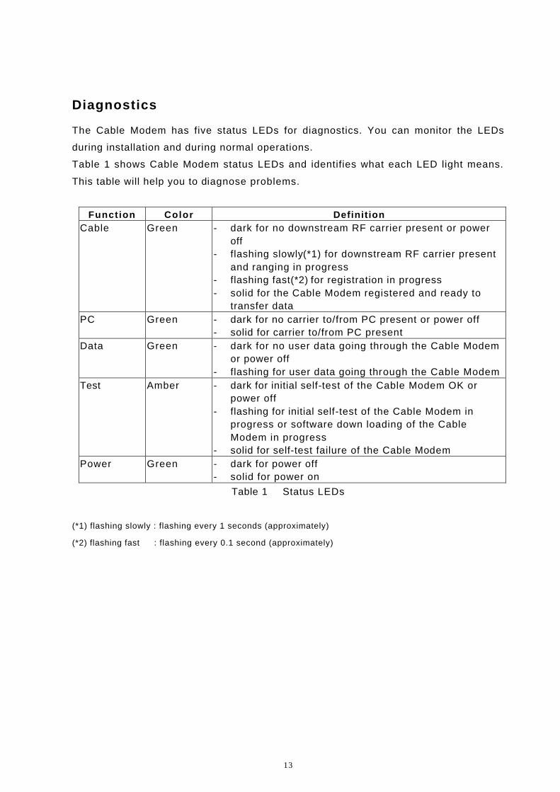
Diagnostics
The Cable Modem has five status LEDs for diagnostics. You can monitor the LEDs
during installation and during normal operations.
Table 1 shows Cable Modem status LEDs and identifies what each LED light means.
This table will help you to diagnose problems.
Function Color Definition Cable Green - dark for no downstream RF carrier present or power
off - flashing slowly(*1) for downstream RF carrier present
and ranging in progress - flashing fast(*2) for registration in progress - solid for the Cable Modem registered and ready to
transfer data PC Green - dark for no carrier to/from PC present or power off
- solid for carrier to/from PC present Data Green - dark for no user data going through the Cable Modem
or power off - flashing for user data going through the Cable Modem
Test Amber - dark for initial self-test of the Cable Modem OK or power off
- flashing for initial self-test of the Cable Modem in progress or software down loading of the Cable Modem in progress
- solid for self-test failure of the Cable Modem Power Green - dark for power off
- solid for power on
Table 1 Status LEDs
(*1) flashing slowly : flashing every 1 seconds (approximately)
(*2) flashing fast : flashing every 0.1 second (approximately)
14
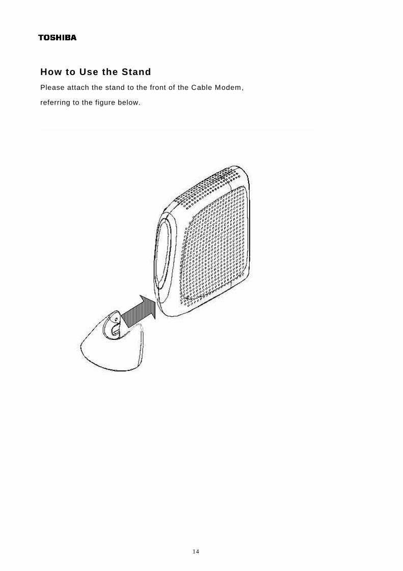
How to Use the Stand
Please attach the stand to the front of the Cable Modem,
referring to the figure below.
15
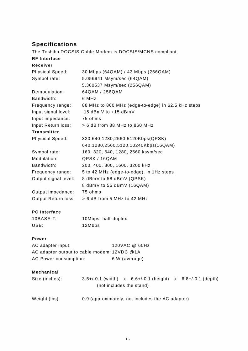
Specifications The Toshiba DOCSIS Cable Modem is DOCSIS/MCNS compliant.
RF Interface
Receiver
Physical Speed: 30 Mbps (64QAM) / 43 Mbps (256QAM)
Symbol rate: 5.056941 Msym/sec (64QAM)
5.360537 Msym/sec (256QAM)
Demodulation: 64QAM / 256QAM
Bandwidth: 6 MHz
Frequency range: 88 MHz to 860 MHz (edge-to-edge) in 62.5 kHz steps
Input signal level: -15 dBmV to +15 dBmV
Input impedance: 75 ohms
Input Return loss: > 6 dB from 88 MHz to 860 MHz
Transmitter
Physical Speed: 320,640,1280,2560,5120Kbps(QPSK)
640,1280,2560,5120,10240Kbps(16QAM)
Symbol rate: 160, 320, 640, 1280, 2560 ksym/sec
Modulation: QPSK / 16QAM
Bandwidth: 200, 400, 800, 1600, 3200 kHz
Frequency range: 5 to 42 MHz (edge-to-edge), in 1Hz steps
Output signal level: 8 dBmV to 58 dBmV (QPSK)
8 dBmV to 55 dBmV (16QAM)
Output impedance: 75 ohms
Output Return loss: > 6 dB from 5 MHz to 42 MHz
PC Interface
10BASE-T: 10Mbps; half-duplex
USB: 12Mbps
Power
AC adapter input: 120VAC @ 60Hz
AC adapter output to cable modem: 12VDC @1A
AC Power consumption: 6 W (average)
Mechanical
Size (inches): 3.5+/-0.1 (width) x 6.6+/-0.1 (height) x 6.8+/-0.1 (depth)
(not includes the stand)
Weight (lbs): 0.9 (approximately, not includes the AC adapter)
16
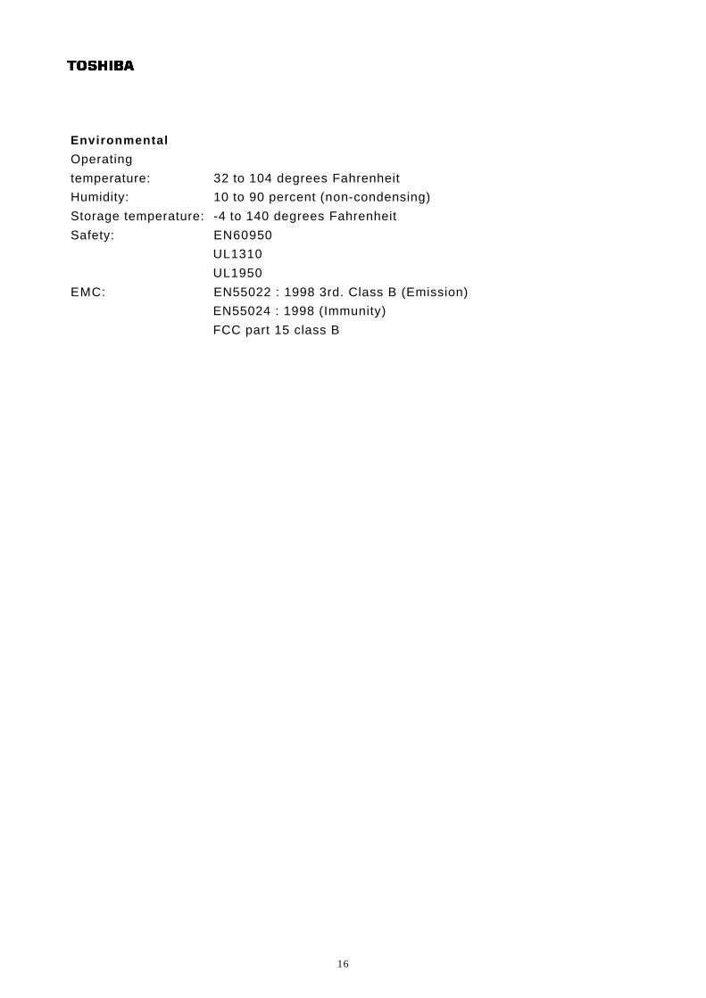
Environmental
Operating
temperature: 32 to 104 degrees Fahrenheit
Humidity: 10 to 90 percent (non-condensing)
Storage temperature: -4 to 140 degrees Fahrenheit
Safety: EN60950
UL1310
UL1950
EMC: EN55022 : 1998 3rd. Class B (Emission)
EN55024 : 1998 (Immunity)
FCC part 15 class B
17
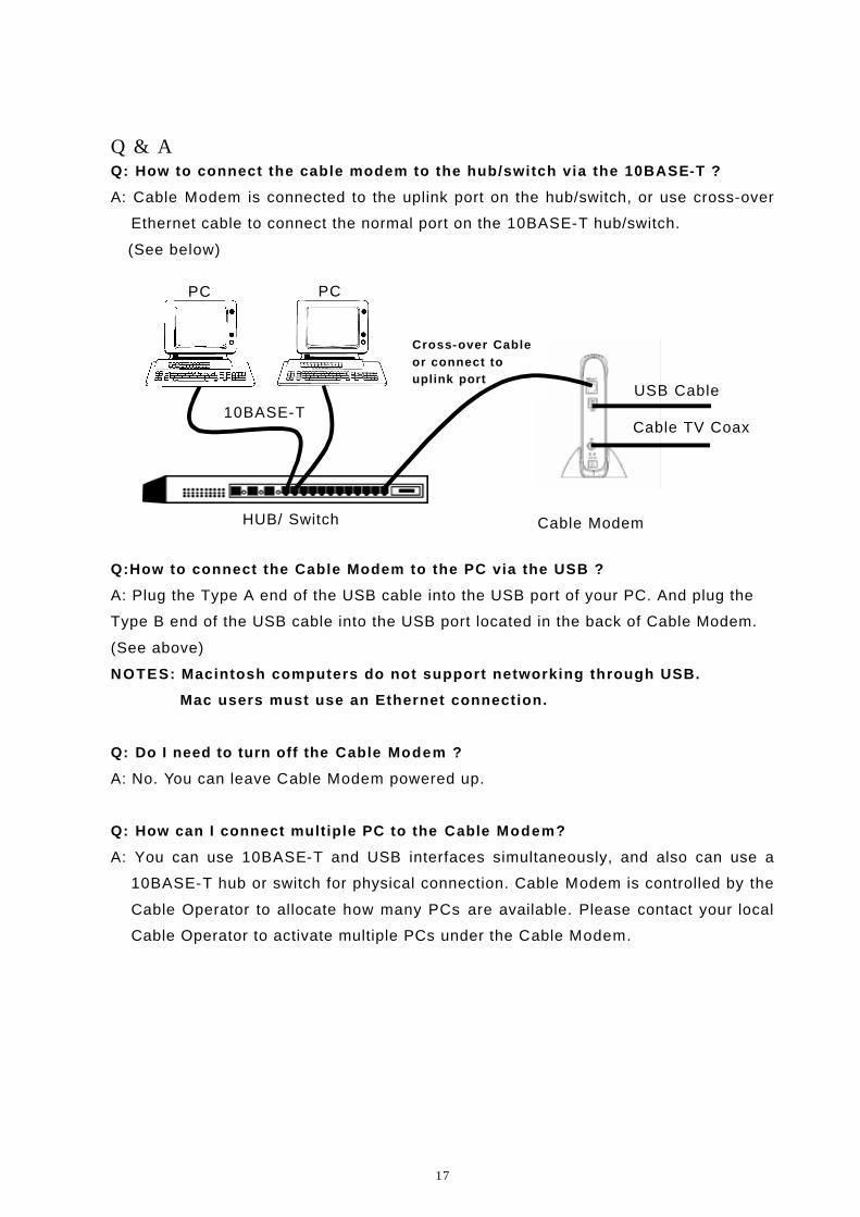
Q & A Q: How to connect the cable modem to the hub/switch via the 10BASE-T ?
A: Cable Modem is connected to the uplink port on the hub/switch, or use cross-over
Ethernet cable to connect the normal port on the 10BASE-T hub/switch.
(See below)
Q:How to connect the Cable Modem to the PC via the USB ?
A: Plug the Type A end of the USB cable into the USB port of your PC. And plug the
Type B end of the USB cable into the USB port located in the back of Cable Modem.
(See above)
NOTES: Macintosh computers do not support networking through USB.
Mac users must use an Ethernet connection.
Q: Do I need to turn off the Cable Modem ?
A: No. You can leave Cable Modem powered up.
Q: How can I connect multiple PC to the Cable Modem?
A: You can use 10BASE-T and USB interfaces simultaneously, and also can use a
10BASE-T hub or switch for physical connection. Cable Modem is controlled by the
Cable Operator to allocate how many PCs are available. Please contact your local
Cable Operator to activate multiple PCs under the Cable Modem.
Cross-over Cable or connect to uplink port
Cable Modem
Cable TV Coax
PC PC
HUB/ Switch
10BASE-T
USB Cable
18
Q: Where can I download the driver for Cable modem?
A: In case of use 10BASE-T interface, the Cable Modem is a stand-alone device that
has a 10BASE-T port. All workstations or hub must have a 10BASE-T port or card
to connect to the Cable Modem. Since the Cable Modem is a stand alone device,
there is no special driver needed on the workstation.
In case of use USB interface, the Cable Modem that connects to a PC running
Microsoft Windows 98SE, 2000, Me or XP via the USB interface, you must install
“USB Driver” in your PC. A CD-ROM, attached this product, provides this driver.
Q: How can I configure the Cable Modem and get monitoring information
from it ?
A: The Cable Modem can only be configured and monitored by your cable operator.
19
Regulatory
<>FCC Notice:
This equipment has been tested and found to comply with the limits for a Class B
personal computer and peripherals, pursuant to Part 15 of the FCC Rules. These
limits are designed to provide reasonable protection against harmful interference in a
residential installation. This equipment generates, uses and can radiate radio
frequency energy and, if not installed and used in accordance with the instructions,
may cause harmful interference to radio communications. However, there is no
guarantee that interference will not occur in a particular installation. If this unit does
cause harmful interference to radio or television reception, which can be determined
by turning the equipment off and on, the user is encouraged to try to correct the
interference by one or more of the following measures:
♦ Reorient or relocate the receiving antenna.
♦ Increase the separation between the equipment and receiver.
♦ Connect the equipment into an outlet on a circuit different from that to which
the receiver is connected.
♦ Consult the dealer or experienced radio/TV technician for help.
<>International declaration of conformity:
This equipment has been tested and found to comply with the requirements of the Low
Voltage Directive 73/23/EEC and the EMC Directive 89/336/EEC. Conformity with
these Directives is based upon compliance with the following harmonized standards:
Safety:
EN60950:1992
EMC:
EN55022 : 1998 Class B
EN61000-3-2 : 1995
EN61000-3-3 : 1995
EN55024 : 1998
IEC61000-4-2 : 1995
IEC61000-4-3 : 1995
IEC61000-4-4 : 1995
IEC61000-4-5 : 1995
IEC61000-4-6 : 1996
IEC61000-4-8 : 1993
IEC61000-4-11 : 1994
20
Glossary 10BASE-T
Unshielded, twisted pair cable with an RJ-45 connector, used with Ethernet LAN. “10”
indicates the speed (10 Mbps), “Base” refers to baseband technology, and “T” means
twisted pair cable.
Cable TV Coax
Cable that allows wide bandwidth transmission over long distances. Coaxial cable
(coax) comprises an inner conductor surrounded by insulation. An outer conductor
wraps around the insulation, which, in turn, is covered by an outer plastic covering.
Ethernet card
A plug-in circuit board installed in an expansion slot of a personal computer. The
Ethernet card (sometimes called a Network Interface Card, or NIC) takes parallel data
from the computer, converts it to serial data, puts it into a packet format, and sends it
over the 10BASE-T LAN cable.
F connector
A type of coaxial connector, labeled RF on the rear of the Toshiba Cable Modem, that
connects the modem to the cable system.
Headend
The equipment, in the central office of the service provider, where the cable signals
originate.
Hybrid Fiber/ Coaxial (HFC) system
A system where the trunk of the cable plant is of fiber technology. Somewhere near
the subscriber ’s home, the fiber is connected to a coaxial cable, and the signal is
converted so that it’s compatible with the fiber media. The coaxial cable then runs
through the branches of the network and is finally dropped into the home.
HUB
A device used to connect multiple computers to the cable modem.
Internet
A collection of interconnected networks used for worldwide computer-based
communications.
IP Address
A unique, 32-bit address assigned to every device in a network. An IP (Internet
Protocol) address has two parts: 1) a network address and 2) a host address. Each
network is assigned an address by a government agency, and each company
administrator assigns an address to each host computer.
21
Modem registration
The process the Toshiba Cable Modem uses to make itself known to the headend
equipment. Once authorized by the router, the modem is assigned upstream and
downstream channels for data communication.
Network driver
A (software) file included with the Ethernet card. The file is loaded on the computer to
allow the computer to recognize the Ethernet card. See Ethernet Card.
RJ-45
Connector on the Toshiba Cable Modem, labeled 10BASE-T, that connects the
modem to a computer or to a HUB.
Subscriber
A computer user in the home who accesses a data service using the Toshiba Cable
Modem.
Subnet
A network subdivision. When subnetting us used, the IP (Internet Protocol) address is
divided into a subnet number and a host number. Hosts and gateways identify the bits
used for the network and subnet number through the use of a subnet mask.
TCP/IP communication stack
Software in the subscriber computer that processes packets through the
communication layers. The subscriber configures the IP address for the computer and
the router default gateway in the software. The TCP/IP communication stack handles
all the communications with the subscriber ’s application.
USB
Universal Serial Bus, standardized for easy connections between the PC and the
other peripherals. USB connects more than computers and peripherals.
22
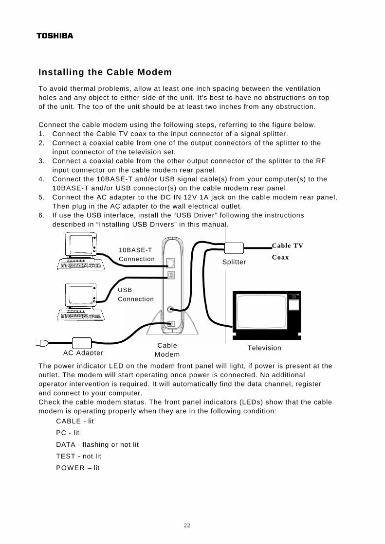
Installing the Cable Modem
To avoid thermal problems, allow at least one inch spacing between the ventilation holes and any object to either side of the unit. It's best to have no obstructions on top of the unit. The top of the unit should be at least two inches from any obstruction. Connect the cable modem using the following steps, referring to the figure below. 1. Connect the Cable TV coax to the input connector of a signal splitter. 2. Connect a coaxial cable from one of the output connectors of the splitter to the
input connector of the television set. 3. Connect a coaxial cable from the other output connector of the splitter to the RF
input connector on the cable modem rear panel. 4. Connect the 10BASE-T and/or USB signal cable(s) from your computer(s) to the
10BASE-T and/or USB connector(s) on the cable modem rear panel. 5. Connect the AC adapter to the DC IN 12V 1A jack on the cable modem rear panel.
Then plug in the AC adapter to the wall electrical outlet. 6. If use the USB interface, install the “USB Driver” following the instructions
described in “Installing USB Drivers” in this manual.
The power indicator LED on the modem front panel will light, if power is present at the outlet. The modem will start operating once power is connected. No additional operator intervention is required. It will automatically find the data channel, register and connect to your computer. Check the cable modem status. The front panel indicators (LEDs) show that the cable modem is operating properly when they are in the following condition:
CABLE - lit
PC - lit
DATA - flashing or not lit
TEST - not lit
POWER – lit
Splitter
AC Adapter Television
10BASE-T
Connection
Cable Modem
Cable TV
Coax
USB
Connection