tosvert vf-a7 pg feedback board instruction manual · · 2015-04-10e6580764② tosvert vf-a7 pg...
TRANSCRIPT

E6580764②
TOSVERT VF-A7
PG FEEDBACK BOARD Instruction Manual
1. INTRODUCTION .........................................................................................3
2. NAMES OF THE PARTS ON THE BOARD ................................................4
3. CONNECTION TO THE INVERTER ...........................................................53.1. Installation to the Inverter ......................................................................53.2. Wiring ....................................................................................................7
4. FUNCTIONAL DESCRIPTION ....................................................................84.1. Vector control with sensor .....................................................................8
4.1.1. PG feedback wiring .........................................................................84.1.2. Selection of encoder type ..............................................................114.1.3. Vector control setting parameter ...................................................124.1.4. Monitoring method for feedback amount.......................................154.1.5. Accuracy of speed control .............................................................15
4.2. Pulse input command (speed command selection).............................164.2.1. Pulse command connection method .............................................164.2.2. Pulse input setting parameter........................................................184.2.3. Monitoring method of pulse input command .................................19
5. EXTERNAL VIEW......................................................................................20
6. SPECIFICATION .......................................................................................21
7. OPTION CABLE ........................................................................................22
8. WARRANTY ..............................................................................................23
NOTE1. Make sure that this instruction manual is delivered to the end user of the PG feed-
back board.2. Read this manual before installing or operating the inverter unit, and store it in a safe
place for reference.
© TOSHIBA Corporation 1999All Rights Reserved.

E6580764②
1
Safety PrecautionsOn the inverter and in its instruction manual, important information is contained for preventing injuries to users
and damages to assets and for proper use of the device. Read the instruction manual attached to the inverter
along with this instruction manual for completely understanding the safety precautions and adhere to the
contents of these manuals.
Handling in general
Danger
NeverDisassemble
▼ Never disassemble, modify or repair the inverter. Disassembling the inverter could cause electric shocks, fire or injuries. Request your TOSHIBA dealer for repairs.
Prohibited
▼ Do not remove connectors when the power is on. It could lead to electric shocks.▼ Do not put or insert foreign objects such as waste cable, bars, or wires into the inverter. It could lead to electric shocks or fire.▼ Do not splash water over the inverter. It could lead to electric shocks or fire.
Mandatory
▼ Wiring should be conducted after turning the inverter power off.▼ Turn off the power immediately in case any abnormalities such as smokes, smells or
abnormal noise are found. Neglect of these conditions could lead to fire. Ask your TOSHIBA dealer for repairs.
Transportation and Installation
Danger
Prohibited
▼ Do not install or operate the inverter if it is damaged or any part is missing from it. Operating the inverter in a defective condition could lead to electric shocks or fire. Ask your TOSHIBA dealer for repairs.▼ Do not put any inflammable material near the inverter. It could catch fire if the inverter sparks because of a breakdown and the like.▼ Do not install the inverter where it could be splashed with water and the like. It could lead to electric shocks or fire.
Mandatory
▼ Inverter must be used under environmental conditions prescribed in this instruction manual. Using the inverter under conditions not specified by the instruction manual could lead to
breakdown.

E6580764②
2
Warning
Prohibited
▼ Do not install the inverter in any place subject to vibrations or it could fall.
Otherwise it can cause injury to people.
Wiring
Danger
Mandatory
▼ Be sure to perform the following preparatory work before proceeding to wiring. Turn the power off. Wait 10 minutes or more after turning the power off and confirm that the charge lamp
(on the inverter) is extinct. Using a circuit tester that has a D.C. voltage measuring capacity of more than 800V,
check to see that the voltage remaining in the D.C. main circuit (between PC and PA)is below 45V.
Failure to do this preparation could lead to electric shocks.▼ Tighten the terminal board fixing screws at the specified torque. Failure to do this could lead to fire.
About operation
Danger
Prohibited
▼ Do not touch inverter terminals when they are energized even if the motor is halted. Touching terminals while the power is energized could lead to electric shocks.▼ Do not wipe the body with a wet cloth. It could lead to electric shocks.▼ Do not pull on the cable It could cause damage or error.
About disposal of Inverter
Warning
Mandatory
▼ Dispose of the inverter as an industrial waste. Unless it is disposed of as an industrial waste, it will become risks for human injury.

E6580764②
3
1. IntroductionThank you for purchasing the PG Feedback Board (PGFB board) for Industrial Inverter, TOSVERT VF-A7
series.
By the use of this optional board, it is possible for the VF-A7 series inverters to conduct pulse row speed
command and vector control with sensor. This instruction manual describes installation and application of
“PGFB board”. Read this manual carefully before using the board.
Keep this manual near at hand of the operator who uses the “PGFB Board” for future reference in the main-
tenance and inspection.
<<<<Description of the PGFB Board type>>>>VEC 002 Z -0
<<<<Confirmation on Accessories>>>>
Following accessories are the options to the PGFB Board.
Upon unpacking, confirm on the following items:
◎Instruction Manual: one (E6580764)
◎Optional cover (to be used when using units with 22kW or less)
◎Board installation stay
◎PGFB Board (printed circuit board)
◎Installation screw set (one bag)
Optional cover
Board installation stay
PGFB Board (printed circuit board)
Installation screw set (one bag)・ M3 support screw x 4 (10mm)・ M3 setting screw x 4・ M3 tap tight screw x 2・ Insulation-lock band
InstructionManual
Revision number
No cable between the inverter and units
Vector compatible type number002: For complementary / open collector type encoder003: For line driver type encoder
Vector control with sensor compatible

E6580764②
4
2. Names of the Parts on the BoardExternal views of the PGFB Board are described in this section together with the names of parts on the
board.
External views and names of parts on the board (terminals)
<VEC002Z>
Board fixing screw hole
Terminal names
Terminal base
Optional connectors
TerminalName
Terminal Function
PGA1 Phase A PG feedback anode sidePGA2 Phase A PG feedback cathode sidePGB1 Phase B PG feedback anode sidePGB2 Phase B PG feedback cathode sidePGZ1 Phase Z PG feedback anode sidePGZ2 Phase Z PG feedback cathode sidePGVC Encoder power terminal (12V)PGCC Encoder common terminal
12345678
PGA1PGA2PGB1PGB2PGZ1PGZ2PGVCPGCC
Board fixing screw hole
<VEC003Z>
ANABNBZNZPGVCPGCC
TerminalName
Terminal Function
A Phase A PG feedback non-inverting sideNA Phase A PG feedback inverting sideB Phase B PG feedback non-inverting sideNB Phase B PG feedback inverting sideZ Phase Z PG feedback non-inverting sideNZ Phase Z PG feedback inverting sidePGVC Encoder power terminal (5V)PGCC Encoder common terminal
12345678
E6580764②
5
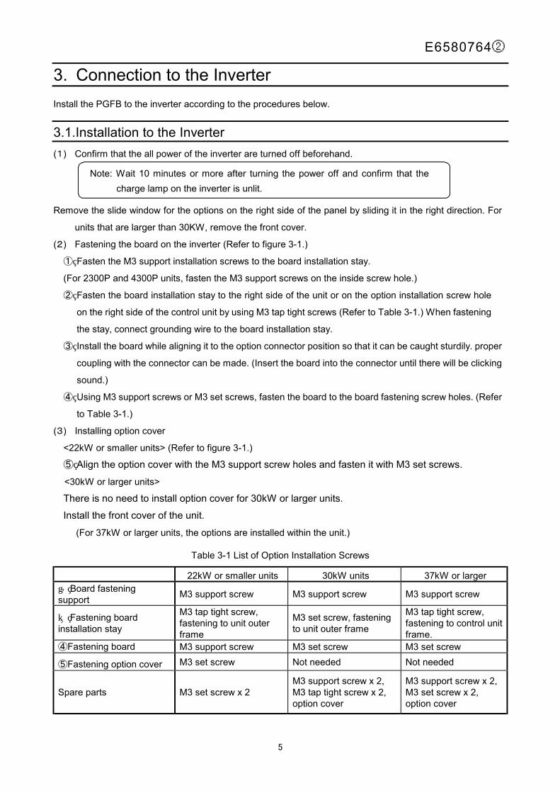
3. Connection to the InverterInstall the PGFB to the inverter according to the procedures below.
3.1. Installation to the Inverter(1) Confirm that the all power of the inverter are turned off beforehand.
Remove the slide window for the options on the right side of the panel by sliding it in the right direction. For
units that are larger than 30KW, remove the front cover.
(2) Fastening the board on the inverter (Refer to figure 3-1.)
① Fasten the M3 support installation screws to the board installation stay.
(For 2300P and 4300P units, fasten the M3 support screws on the inside screw hole.)
② Fasten the board installation stay to the right side of the unit or on the option installation screw hole
on the right side of the control unit by using M3 tap tight screws (Refer to Table 3-1.) When fastening
the stay, connect grounding wire to the board installation stay.
③ Install the board while aligning it to the option connector position so that it can be caught sturdily. proper
coupling with the connector can be made. (Insert the board into the connector until there will be clicking
sound.)
④ Using M3 support screws or M3 set screws, fasten the board to the board fastening screw holes. (Refer
to Table 3-1.)
(3) Installing option cover
<22kW or smaller units> (Refer to figure 3-1.)
⑤ Align the option cover with the M3 support screw holes and fasten it with M3 set screws.
<30kW or larger units>
There is no need to install option cover for 30kW or larger units.
Install the front cover of the unit.
(For 37kW or larger units, the options are installed within the unit.)
Table 3-1 List of Option Installation Screws
22kW or smaller units 30kW units 37kW or larger① Board fastening support M3 support screw M3 support screw M3 support screw
② Fastening board installation stay
M3 tap tight screw,fastening to unit outerframe
M3 set screw, fasteningto unit outer frame
M3 tap tight screw,fastening to control unitframe.
④Fastening board M3 support screw M3 set screw M3 set screw
⑤Fastening option cover M3 set screw Not needed Not needed
Spare parts M3 set screw x 2M3 support screw x 2,M3 tap tight screw x 2,option cover
M3 support screw x 2,M3 set screw x 2,option cover
Note: Wait 10 minutes or more after turning the power off and confirm that thecharge lamp on the inverter is unlit.

E6580764②
6
Figure 3-1 Installation to inverter
Option cover(only for 22kW or smaller units)
M3 support screw
With 2300P and 4300Punits, fasten to insidescrew hole.
M3 tap tight screw
Board installation stay
M3 set screw
With 2300P and 4300Punits, fasten with M3 setscrew.(Fastening to plate)
M3 set screw.
M3 support screw
M3 set screw
⑤
③
② ①
④
Connectgrounding wire.

E6580764②
7
3.2. Wiring
When conducting wiring, follow the instructions bellow.
♦ Use twisted pair shield wire for signal lines.
♦ Applicable wire size is 0.2 to 0.75 mm².
♦ Peel the wire end for about 5 mm.
♦ When wiring, use a screw driver with the blade thickness of about 0.4 mm and width of
about 2.5 mm.
♦ Tightening torque for terminal base should be about 0.22 to 0.25 N・m.
♦ Bind the signal lines together with the attached insulation-lock band (attached parts) and connect them
to M3 support screw for fastening the board.
♦ Never bind the signal lines and main circuit wiring.
<Encoder output format and PGFB board interface>
Encoder output format PGFB board wiring PGFB board interface
Com
plem
enta
ry
Vcc
0 V
A・B・Z
A・B・Z
Ope
n co
llect
or
Vcc
0 V
A・B・Z
PGB2
PGB1
PGA2
PGA1
PGZ2
PGZ1
470 Ω
470 Ω
PGA1PGB1PGZ1
PGA2PGB2PGZ2
Photo-couplerVF:1.2 to 1.7V
<VEC002Z>
Line
driv
er
A・B・Z
A・B・Z
26LS31 equivalent
NA
A
NB
B
NZ
Z
ABZ
NANBNZ 26LS32 equivalent
<VEC003Z>

E6580764②
8
4. Functional DescriptionIn this section, functions added by the installation of the PGFB board, on top of the standard VF-A7 functions,
are described.
4.1. Vector control with sensor
Using the pulse-row feedback signal from the encoder installed on the motor shaft or load rotation shaft,
vector control with sensor can be conducted.Speed control operation :0 speed to 150% torque, speed control range 1:1000 (1000 ppr-PG)
speed accuracy ±0.02% (50Hz base digital input)Torque control operation :Torque control accuracy: ±10% (torque control range: –100% to 100%)
4.1.1. PG feedback wiring
In case of VEC002 (complementary/open collector)
As for the pulse input signals, PGA1 and PGA2 are connected for Phase A, PGB1 and PGB2 are connect-
ed for Phase B, and PGZ1 and PGZ2 are connected for Phase Z.
(The wiring for Phase Z is done only when using Z-marker is necessary.)
The polarity of the pulse input signals should be as follows:
+ side: PGA1, PGB1, PGZ1 - side: PGA2, PGB2, PGZ2
The encoder installation direction and signal line wiring should be determined so that the signal
that are fed back from the encoder will show the waveform shown in Figure 4-1 in terms of the mo-
tor rotation direction.
★★★★ Forward rotation or reverse rotation is judged from the feedback pulses of Phase A and Phase B
(2-phase pulse that have 90 degrees of phase difference). Therefore, it should be noted that,
when connections are wrong, there is possibility for abnormal rotation of the motor.
A
A
BB
PGA1PGA2
PGB1PGB2
PG
↑V A
↑VB
Phase A(VA) Phase A(VA)
Forward rotation Reverse rotationPhase B(VB) Phase B(VB)
X2X1 X3 X4
T
Phase difference:Xn≧0.15T(n=1,2,3,4)
Figure 4-1 Judgement on normal and reverse rotations by the PG feedbackof two phases (Phases A and B)
<When PG feedback signal is single phase>
1. For PG feedback signal, connect terminals PGA1 and PGA2.2. The judgement on forward rotation and reverse rotation is impossible. Only the speed control mode is applicable.

E6580764②
9
Figure 4-2 Example of complementary encoder connection
Figure 4-3 Example of open collector encoder connection
A
A
BBVcc0V
VF-A7
I MR
S
T
When single phase, connectterminals PGA1 and PGA2only.
U
V
W
ST
FRCC
PGA1
PGA2PGB1PGB2PGVCPGCC
VEC002Z
E
Free run is stopped when OFF.
Forward rotation with ON andreduce speed and stop with OFF
Reverse rotation with ON andreduce speed and stop with OFF.When both forward and reverserotation is ON, reverse rotation.
PG
(In case of standard shipment setting.)
A
BVcc0V
Vcc
Vcc
VF-A7
I MR
S
T
When single phase, connectterminals PGA1 and PGA2
U
V
W
ST
FRCC
PGA1
PGA2PGB1PGB2PGVCPGCC
VEC002Z
E
Free run is stopped when OFF.
Forward rotation with ON andreduce speed and stop with OFF
Reverse rotation with ON andreduce speed and stop with OFF.When both forward and reverserotation is ON, reverse rotation.
PG
(In case of standard shipment setting.)

E6580764②
10
★ Caution in case of using open collector encoder connection
In case using pulse command oscillator and open collector encoder, the rise time of the voltage when the
transistor is OFF tends to be longer than the fall time at the time when the transistor is ON. Therefore, if the
maximum input frequency becomes higher, the pulse duty cannot maintain the 50±10% specification.
Conduct derating on the maximum input frequency so that the pulse duty will be within the following speci-
fication range.
<Derating computation formulae of open collector’s maximum input pulse frequency >
0.8 / (Maximum input frequency x A) – Voltage rise time = 3 x 10 –6 …..①
A : (single phase input: 2) (two-phase input: 4)
Voltage rise time : Encoder exclusive pulse rise time + R x C
Encoder exclusive pulse rise time (s) : Please inquire at the encoder manufacturer.
R (Ω) (Input resistance) : internal resistance 1000(Ω)+external resistance value
(in case there is external resistance)
C(F) (Cable static capacity) : Please inquire at the cable manufacturer.
<Example>
Encoder : LBJ-005-500 (SUMTAK), 2-phase input Encoder pulse rise time: 0.35 x 10⁻⁶(s)
Cable : ROVV-SB-0.2-5P-10m (Furukawa Electric) Static capacity: 120 x 10 –12 (F/m) x 10 (m)
From Formulae①
0.8 / (Maximum input frequency x A) – Voltage rise time = 3 x 10 –6
Voltage rise time = (0.35 x 10 –6) + 1000 x (120 x 10-12 x 10) = 1.55 x 10⁻⁶
[Maximum input frequency] ≦87912 (Pulse/s) [Single phase input]
≦43956 (Pulse/s) [Two-phase input]
The case of VEC003(Line Driver)
As for the PG feedback signals, Terminal A and NA are connected for Phase A, Terminal B and NB are
connected for Phase B, and Terminal Z and NZ are connected for Phase Z. (The connection for Phase Z is
made only when reading Z-marker is necessary.)
The polarity of the pulse input signal should be as follows.
Non-inverting input side: A, B, Z Inverting input side: NA, NB, NZ
The signal feedback from the encoder should have the waveform shown in Figure 4-1 in terms of
the motor rotation direction. The encoder installation direction and signal wiring should be done
accordingly.
★★★★ Forward rotation or reverse rotation is judged from the feedback pulses of Phase A and Phase B
(2-phase pulse that have 90 degrees of phase difference). Therefore, it should be noted that,
when connections are wrong, there is possibility for abnormal rotation of the motor.
E6580764②
11
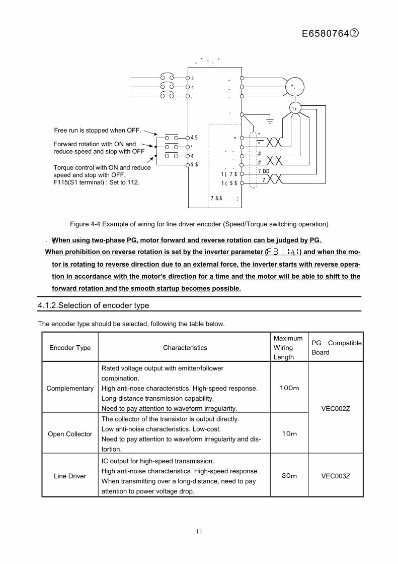
Figure 4-4 Example of wiring for line driver encoder (Speed/Torque switching operation)
★ When using two-phase PG, motor forward and reverse rotation can be judged by PG. When prohibition on reverse rotation is set by the inverter parameter ( = ) and when the mo-
tor is rotating to reverse direction due to an external force, the inverter starts with reverse opera-
tion in accordance with the motor’s direction for a time and the motor will be able to shift to the
forward rotation and the smooth startup becomes possible.
4.1.2. Selection of encoder type
The encoder type should be selected, following the table below.
Encoder Type CharacteristicsMaximumWiringLength
PG CompatibleBoard
Complementary
Rated voltage output with emitter/followercombination.High anti-nose characteristics. High-speed response.Long-distance transmission capability.Need to pay attention to waveform irregularity.
100m
Open Collector
The collector of the transistor is output directly.Low anti-noise characteristics. Low-cost.Need to pay attention to waveform irregularity and dis-tortion.
10m
VEC002Z
Line Driver
IC output for high-speed transmission.High anti-noise characteristics. High-speed response.When transmitting over a long-distance, need to payattention to power voltage drop.
30m VEC003Z
A
A
BBVcc0V
VF-A7
I MR
S
T
U
V
W
ST
FS1CC
A
NABNB
PGVCPGCC
VEC003Z
E
Free run is stopped when OFF.
Forward rotation with ON andreduce speed and stop with OFF
Torque control with ON and reducespeed and stop with OFF.F115(S1 terminal) : Set to 112.
PG

E6580764②
12
4.1.3. Vector control setting parameter
During operation with vector control with sensor, it would be necessary to set the following parameters
shown in the table below.
Table 4-1 <Basic parameters>
Title FunctionName Parameter Setting Setting at Ship-
ment0V/F
Selection0: Constant torque characteristics1: Squared reduced torque characteristics2: Automatic torque boost3: Sensorless torque control (speed)4: Automatic torque boost + automatic energy conservation5: Sensorless vector control + automatic energy conservation6: V/F 5-point setting7: Sensorless vector control (speed/torque switching)8: PG feedback vector control (speed/torque switching)9: PG feedback vector control (speed/position switching)
Standard :speed control
When conducting vector control with sensor (speed/torque control) with this board option, = shouldbe set.For torque control operation, it is necessary to allocate control switching (torque/position) to one of the ter-minal function selection to (input terminal function selection 1 to 8), in addition to theabove parameters.For details of adjustment methods by the speed control command and torque control command, refer to theinverter manual.
Table 4-2 Extended ParameterTitle Function Name Parameter Setting Setting at Shipment
Number of PG input pulse 1~9999 500Selection of number of PG inputphases
1: Single phase input2: 2-phase input
0
Current control proportional gain 0.1~1000 Depends on type.Current control integral gain 0.1~1000 Depends on type.Speed loop proportional gain 3.2~3270 Depends on type.Speed loop integral gain 0.8~125.0(rad/sec) Depends on type.Auto tuning 0: No auto tuning (internal table)
1: Motor constant initialization2: Auto tuning (0 after execution)
0
Slip frequency gain 0.00~2.55 0.60Motor constant 1 0.01~100000mΩ Depends on type.Motor constant 2 0.01~100000mΩ Depends on type.Motor constant 3 0.1~6500mH Depends on type.Motor constant 4 0.1~100.0 1.0Motor constant 5 0.01~650.0mH Depends on type.Number of poles of motor 2,4,6,8,10,12,14,16 4Rated capacity of motor 0.1~280kW Depends on type.Motor type 0: TOSHIBA Standard Motor 1
1: TOSHIBA VF motor2: TOSHIBA V3 motor3: TOSHIBA Standard motor 24: Other
0
The motor constant parameter ( to ) requires setting according to the motor used.For details, refer to the inverter manual.

E6580764②
13
(1) The PG number of input pulses ( ) is the number of encoder output pulses per one motor rota-
tion.
(2) For PG input phase number selection ( ), set as follows:
If the encoder pulse is single-phase:
If the encoder pulse is two-phase (Phase A and Phase B or Phase A and Pulse b + Z origin signal):
When the settings for the above (1) and (2) are wrong, the motor rotation will become abnormal.
(3) Adjustment methods for current control ratio gain ( ) and current control integration gain (
):
These need to be adjusted when it is necessary to fine-tune torque responses. (Normally, standard setting
should be used.) For details of adjustment, refer to the inverter manual.
(4) Adjustment method for speed loop ratio gain ( ) and speed loop integration gain
( )
The principle of the feedback control is a proportional action. This action produces output in proportionto the speed deviation. It is a simple mechanism but it takes some time until the speed becomes stable.Proportional action merely produces some offset values. (The speed deviation will not be eliminatedcompletely with reference to the command frequency.)In order to eliminate the offset, integration action is effective where the output is calculated by theaccumulation of past deviations (from start of operation until now) and added to the proportional action.
<Speed loop ratio gain>
Adjustments are necessary in accordance with the inverter capacity and load inertia ratio.
Set the ratio referring the formulae below as the rule of thumb.
Speed loop ratio gain = (50 x a x Pw) x J 0.12
A : Coefficient by number of motor poles (2 poles: 1.8 4 poles: 2.0 6 poles: 2.2)
PW : Inverter capacity (Example: in case of 3.7kW unit Pw=3.7)
J : Load inertia/TOSHIBA standard motor inertia
(Example: In case of inertia ratio being 4, J = 4)
<Speed loop integration gain>
Standard setting at shipment should be used usually.

E6580764②
14
In case fine-tuning of speed response is necessary, adjust parameters by the following procedure.
Measurement device needed for adjustment: Waveform measurement device such as an oscilloscope.
① Connect the probe of the measurement device to the analog monitor output terminal of the inverter
(between the FM terminal and CC terminal).
Set FM terminal output to Speed Feedback (real-time value). (Refer to 4.1.3 Monitoring method for
feedback amount.)
② Set the acceleration time to minimum, so that there will be no over-current stall.( blinking)
③ Set the Operational Control Setting ( ) and Speed Command Setting ( ) to panel in-
put effective. ( =” ”, =” ”)
④ Set the Speed Setting to about 10Hz and press (RUN) key to measure the speed response wave-
form at operation start. Press (STOP) key to stop operation.
⑤ In order to improve the speed response, gradually make the speed ratio gain greater
( ) and repeat above④ operation and adjust to immediately prior to motor oscillation.
⑥Adjust the speed loop integration gain ( ). Repeat the operation in④ above and adjust the
parameter so that the speed deviation is contained at expected response time.
This concludes the speed loop gain setting.

E6580764②
15
4.1.4. Monitoring method for feedback amount
Motor rotation speed can be monitored.
The motor is equipped with status monitor which is displayed on the panel and analog monitor which used
analog output terminals (FM, AM terminals)
Set items① and② for motor speed monitoring.
① Speed feedback (real-time value) (Unit: Hz/free unit)
The real-time display of motor speed can be made (Monitor display setting: ).
② Speed feedback (one-second filter) (Unit: Hz/free unit)
The filtered motor speed (feedback value) is displayed. (Monitor display setting: ).
The monitoring for the above① and② is possible also in cases except for = (PG feedback vector
control operation). For example, the monitoring can be used for confirmation of the initial PG feedback amount
in open loop (V/F operation and the like).
<Setting method for status monitoring>
In order to monitor motor rotation speed in condition monitoring, it is necessary to change the setting for
extended parameters ( to ).
Refer to <Monitoring Operating Condition) section of the inverter manual.
<Setting method for analog monitoring>
In order to monitor motor rotation speed by the analog output terminal, it is necessary to change the setting
for basic parameter ( , ) and extended parameter ( , ).
Refer to (Meter Setting and Calibration) section of the inverter manual.
4.1.5. Accuracy of speed control
The accuracy of speed control with the PG feedback can be obtained by the following formulae.
Accuracy of speed control = Command frequency accuracy + feedback detection accuracy
Command frequency accuracy=± 0.01(Hz)F (Hz)c
×100×12
[%]
(using digital command)
Feedback detection accuracy=±1
2 0 04F P PG PHC ( ) .× × × × 100 × 1
2 [%]
FC Inverter output frequency
P : Number of motor poles
PG : Number of PG pulses/rotation
PH : Single Phase = 1, Two-Phase = 4
0.04 : Response speed of 40ms

E6580764②
16
4.2. Pulse input command (speed command selection)
Depending on the software version, the commands may not be compatible.Please confirm with the inverter manual.
It is possible to input inverter operation frequency command by pulse signals.(Only with VEC002Z).
This command cannot be used when vector control operation with sensor is effective.
・ Inverter output frequency can be controlled in ratio with the pulse output signal from the pulse oscillator.・ By inputting two-phase pulse with 90 degrees phase difference, it is possible to input forward and reverse rotation commands.
4.2.1. Pulse command connection method
Two-phase pulse input command
1. Connect pulse input signal to the point between terminals PGA1 and PGA2 on phase A and for between
terminals PGB1 and PGB2 .on phase B
2. The polarity of the pulse input signals should be as follows:
+ side: PGA1 and PGB1 - side: PGA2 and PGB2
3. Forward and reverse operation can be judged by the pulse from the phase A and B by using a judgement
circuit together with the operational frequency command.
4. The judgement on forward and reverse rotation is made as shown in Figure 4-5.
A
A
BB
PGA1PGA2
PGB1PGB2
Pulse oscillator↑V A
↑VB
Phase A(VA) Phase A(VA)Forward rotation Reverse rotationPhase B(VB) Phase B(VB)
X2X1 X3 X4
T
Phase difference:Xn≧0.15T(n=1,2,3,4)
Figure 4-5 Judgement on forward and reverse rotation by the two-phase (Phase A and
Phase B) pulse rows
<Caution when using open collector method>
When using open collector method in 4.1.1, the maximum frequency should be derated by
referring to the caution item.
The case for single-phase pulse input command
For the pulse input signal, connect between PGA1 and PGA2.
For switching between forward and reverse rotation, with = (Terminal input validation), ON and
OFF actions between Terminal F-CC and R-CC are used.

E6580764②
17
VF-A7 MCCB
R U
S V IM
T W
E
VEC002Z Pulse oscillator ST PGA1
F PGA2
R PGB1
CC PGB2
When using in singlephase, connect the pulseoscillator between PGA1and PGA2.
With ON, forward rotationand with OFF, speedreduction and stop.
(with ON, reverse rotation,with OFF, speed reductionand stop.)
(When ON for both forward and reverserotation, reverse rotation.)
With OFF, free run is stopped.
Figure 4-6 Example of connection when operating on pulse row command (speed command)

E6580764②
18
4.2.2. Pulse input setting parameter
Table 4-3 Necessary Parameter for pulse input setting
Title Function Name Adjustment RangeSetting atShipment
Speed command selection :PG pulse input setting
Number of PG input pulse *1 ~
Selection of number of PG input phases :Single-phase input:Two-phase input
PG reference point♯1 *2~
PG reference point♯1 frequency *2~ *3
PG reference point♯2 *2~
PG reference point♯2 frequency *2~ *4
*1: Number of PG of input pulse ( ) is the number of pulse per one (1) Hz.The operation frequency command value of the inverter is expressed by the followingformulae.
Frequency command value = Pulse input frequency
*2 Gain and bias adjustment method against the pulse input frequency is as expressed inFigure 4-8.
Frequency command [Hz ]
Upper limit frequency
0 100 [%]
Pulse input frequency
*4
Figure 4-7 Pulse input frequency and frequency command value
*3: is the highest frequency.
*4: Pulse input frequency 100(%) value is the maximum value at its highest.
Pulse input frequency 100(%) value = ×

E6580764②
19
4.2.3. Monitoring method of pulse input command
The pulse input command frequency can be monitored.
In order to monitor the pulse input command frequency, set items of the monitor display as shown
below.
① Operation frequency command value [Unit: Hz/free unit]
The pulse input command frequency can be confirmed even before the motor is used.
Initial value can be confirmed for the combination testing.
For setting method of the condition monitor, refer to the inverter instruction manual in the “monitoring op-
eration condition” section.

E6580764②
20
5. External ViewWhen installing, do not forget the option space.
External view of PGFB board / Unit external dimension when installing the board. (Unit: mm)
Option board dimension External dimension when installing the unit①
<22kw or smaller unit>
External dimension when installing the unit②
<30kw or smaller unit>
External dimension when installing the unit③
<37kw or larger unit>
Board is contained within the unit.
46
65
39
70
27
28
65
27

E6580764②
21
6. Specification<Environment Specification>
Item Specification
Use EnvironmentIndoor, less than 1,000 m from the sea level.No direct sunlight, corrosive or explosive gas, steam, cutting dusts or dusts,grinding solution, and grinding oil.
Ambient Temperature -10 to + 50℃Storage Temperature -25 to +65℃
Relative Humidity 20 to 90 % (No condensation)Vibration 5.9m/s² or less
<Control Specification>
Type VEC002Z VEC003Z
Full-vectoroperation withsensor
Speed control operation[From 0 to 150% torque, speed control range: 1:1000(1000ppr PG), speed accuracy ±0.02% (50 Hz base digital input)]Torque control operation: [torque control accuracy ±10%, (torque control range: -100to 100%)]
PG Method Complementary, Open-collector Line driverPG Wiring Length 100m (Max.)(Complementary) 30m (Max.)PG Power Supply 12V -160mA 5V-160mA
Max. Pulse InputFrequency
120kHz or less (single-phase),60kHz or less ( two-phase)
* (In case of 2-phase open collector method, deleting need to be considered)Pulse duty: 50±10%
Pulse input voltage 12V DC to 15V DC Line Driver (26LS31 equivalent)
RecommendedEncoder
Manufacturer: SUMTAK Co., Ltd.Type: LBJ seriesSupply Voltage: 12VOutput Method: complementary output
Manufacturer: SUMTAK Co., Ltd.Type: LBJ seriesSupply Voltage: 5VOutput Method: line-driver output
Encoder Wiring
(RecommendedCable)
Type of Wire: Twisted Pair Shield CableConductor Resistance: Conductor Resistance (Ω/m) x cable length (m) x 2 x power consumption (A) <VD (V) VD(V): 1.0(V) (VEC002Z) 0.3(V) (VEC003Z)Applicable Wire: 0.2 to 0.75mm² (Power Line) In case of 0.2mm² cable, maximum of 30m (VEC002Z) maximum of 10m (VEC003Z)KURAMO Electric: KVC-36SB , Furukawa Electric: ROVV-SB

E6580764②
22
7. Option CableTOSHIBA’s sensor cable for VFV3 motor:
When using RAD320-CA1 (option), conduct terminal processing on the CN8 side, referring to Table 7-1.
Table7-1 Processing of VFV3 sensor cable
CN8CannonPlug
WireColor*
SignalName
Description(PG terminal sideprocessing)
CN8CannonPlug
WireColor*
SignalName
Description(PG terminal sideprocessing)
1 A Brown - Not used (cutting) 9 - - - Not used
2 BBrown/
White- Not used (cutting) 10 H Blue Z
Connect toZ terminal.
3 C Red - Not used (cutting) 11 J Yellow NAConnect toNA terminal.
4 DRed/White
- Not used (cutting) 12 KYel-
low/White
AConnect toA terminal.
5 E Orange MT Not used (cutting) 13 L Green NBConnect toNB terminal.
6 FOr-
ange/White
MT Not used (cutting) 14 MGreen/
WhiteB
Connect toB terminal.
7 GBlue/White
NZConnect to NZterminal.
15 N Gray COMConnect toPGCC terminal.
8 - - SHLDConnect to inverterE terminal.
16 PGray/White
P5Connect toPGVC terminal.
*There are cases where green may have been changed. Therefore, be sure to confirm on the terminal num-
ber of the connector before processing to wire.
CN8
CN8 (Disassemble.)
Remove screw
Cannon plug

E6580764②
23
8. WarrantyTOSHIBA provides guarantee with the product under the following conditions.
1. If and when a trouble occurs on the board properly installed and handled within one year of delivery, and if
the trouble is clearly attributable to defects inherent in our design and manufacture, the product will be re-
paired free of charge.
2. The warranty covers only the delivered board.
3. Even in the term of the warranty, repair/adjustment service will be changed for the following cases.
Fault or damage resulting from misuse, unauthorized modification or repair.
Fault or damage resulting from falling down of the product or traffic accident during transportation.
Fault or damage originating from fire, salt water/salty breezes, some kind of gas, arthquake, storm or
flood, lightning, abnormal supply voltage, other natural disasters.
Fault or damage caused by improper use of the inverter as it is used for a purpose out of its original ap-
plication.
4. If field inspection of the inverter is carried out at the spot of installation, all travelling expenses
incurred will be charged. If there is another special warranty contracted for the inverter, the special warranty
has priority over this warranty.