total station setup and operation - southalabama.edu station... · trouble-shooting the rem...
TRANSCRIPT
Total Station Setup and Operation
Sokkia SET Total Station
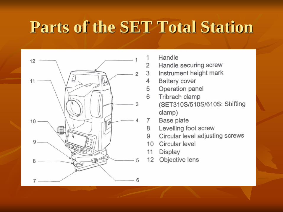
Parts of the SET Total Station
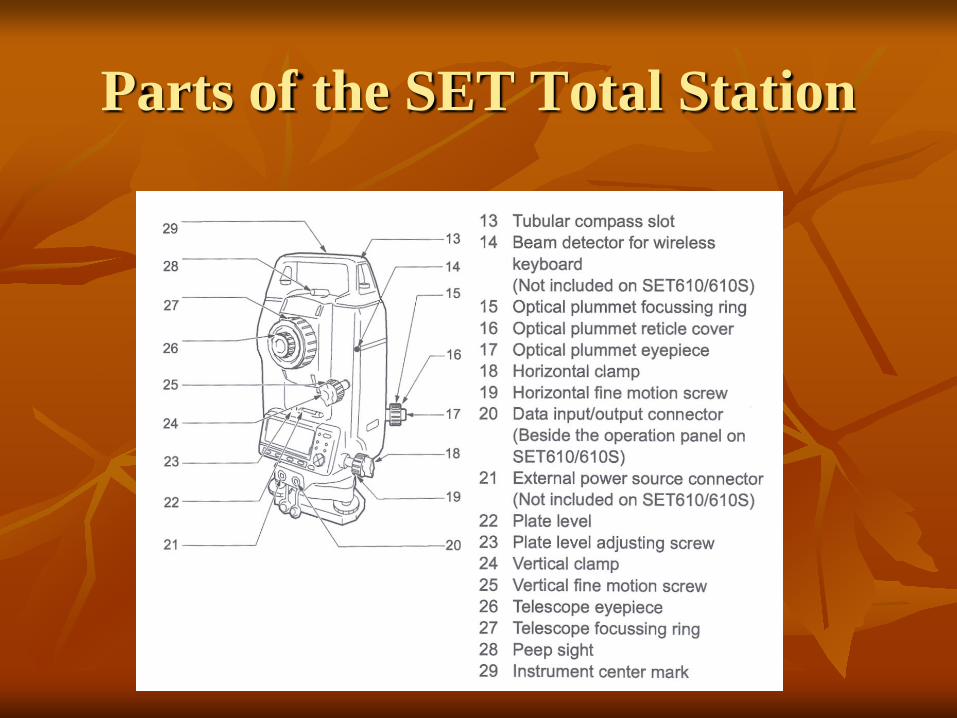
Parts of the SET Total Station
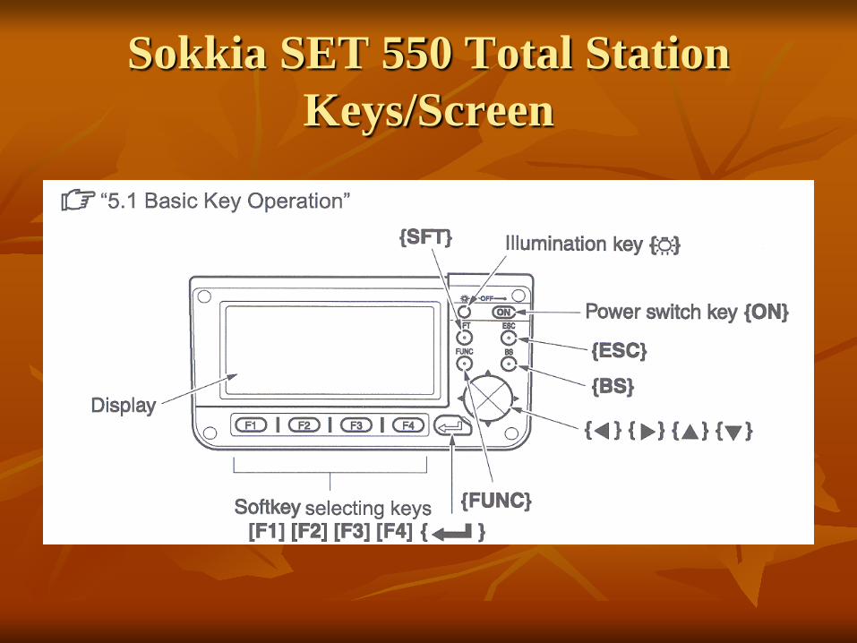
Sokkia SET 550 Total Station Keys/Screen

SET 550 Menu Pages

Leveling the Total Station
Leveling the Total Station must be accomplished to sufficient accuracy otherwise the instrument will not report results
Leveling the instrument takes 30 to 45 minutes – make sure you can see all targets from the instrument station before going through the process
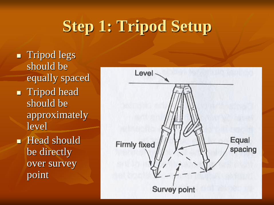
Step 1: Tripod Setup Tripod legs
should be equally spaced
Tripod head should be approximately level
Head should be directly over survey point
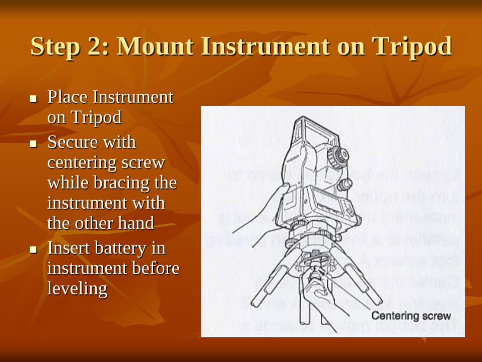
Step 2: Mount Instrument on Tripod
Place Instrument on Tripod
Secure with centering screw while bracing the instrument with the other hand
Insert battery in instrument before leveling
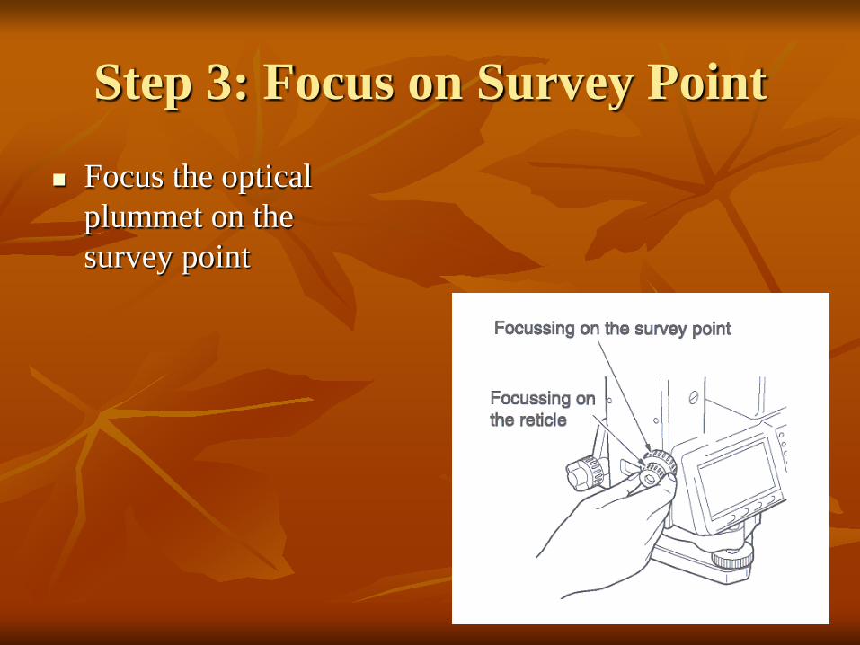
Step 3: Focus on Survey Point
Focus the optical plummet on the survey point

Step 4: Leveling the Instrument
Adjust the leveling foot screws to center the survey point in the optical plummet reticle
Center the bubble in the circular level by adjusting the tripod legs

Step 4: Leveling … Loosen the horizontal clamp and turn instrument until
plate level is parallel to 2 of the leveling foot screws Center the bubble using the leveling screws- the
bubble moves toward the screw that is turned clockwise
Rotate the instrument 90 degrees and level using the 3rd leveling screw
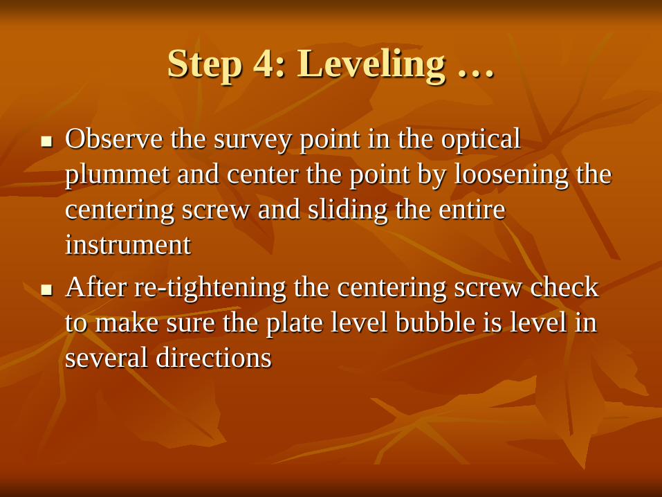
Step 4: Leveling …
Observe the survey point in the optical plummet and center the point by loosening the centering screw and sliding the entire instrument
After re-tightening the centering screw check to make sure the plate level bubble is level in several directions
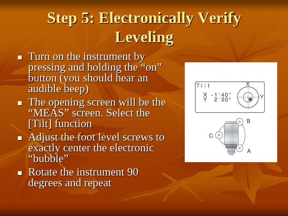
Step 5: Electronically Verify Leveling
Turn on the instrument by pressing and holding the “on” button (you should hear an audible beep)
The opening screen will be the “MEAS” screen. Select the [Tilt] function
Adjust the foot level screws to exactly center the electronic “bubble”
Rotate the instrument 90 degrees and repeat
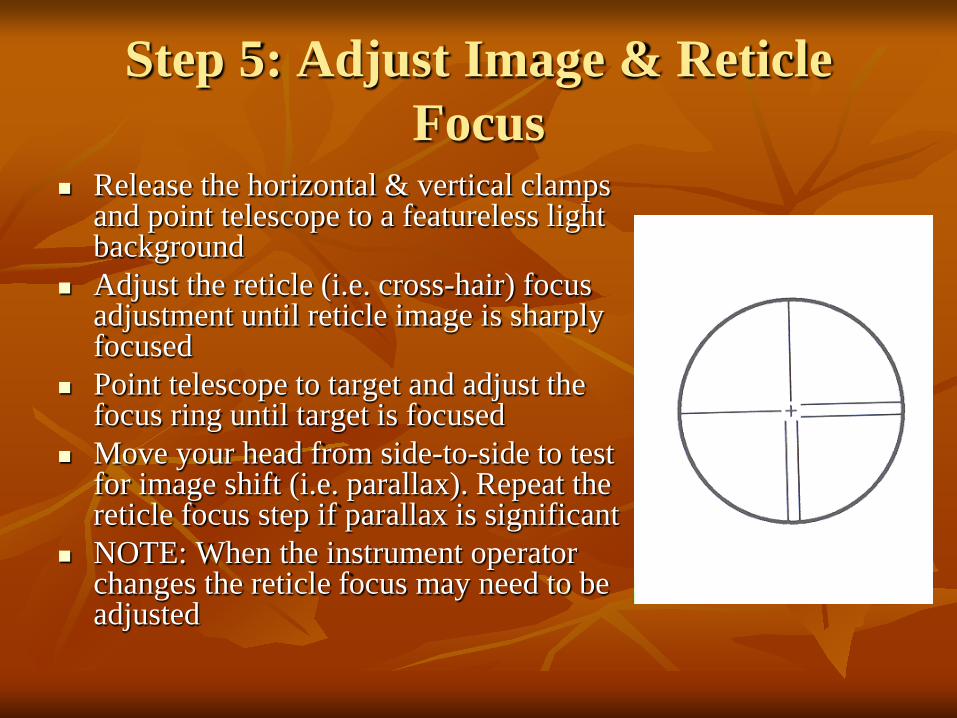
Step 5: Adjust Image & Reticle Focus
Release the horizontal & vertical clamps and point telescope to a featureless light background
Adjust the reticle (i.e. cross-hair) focus adjustment until reticle image is sharply focused
Point telescope to target and adjust the focus ring until target is focused
Move your head from side-to-side to test for image shift (i.e. parallax). Repeat the reticle focus step if parallax is significant
NOTE: When the instrument operator changes the reticle focus may need to be adjusted
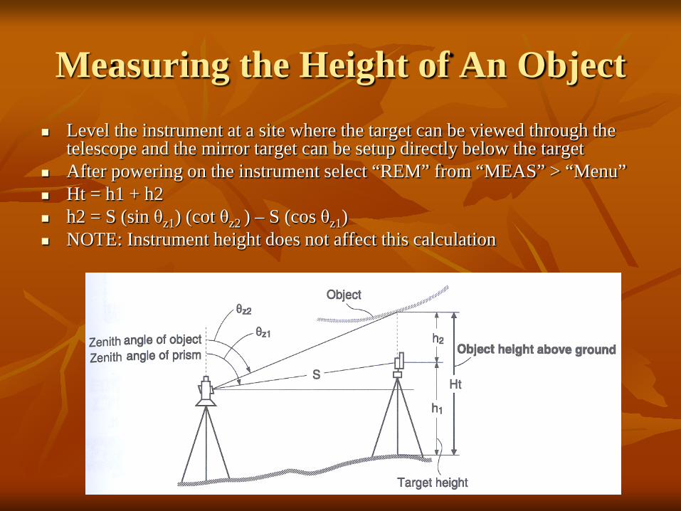
Measuring the Height of An Object Level the instrument at a site where the target can be viewed through the
telescope and the mirror target can be setup directly below the target After powering on the instrument select “REM” from “MEAS” > “Menu” Ht = h1 + h2 h2 = S (sin θz1) (cot θz2 ) – S (cos θz1) NOTE: Instrument height does not affect this calculation
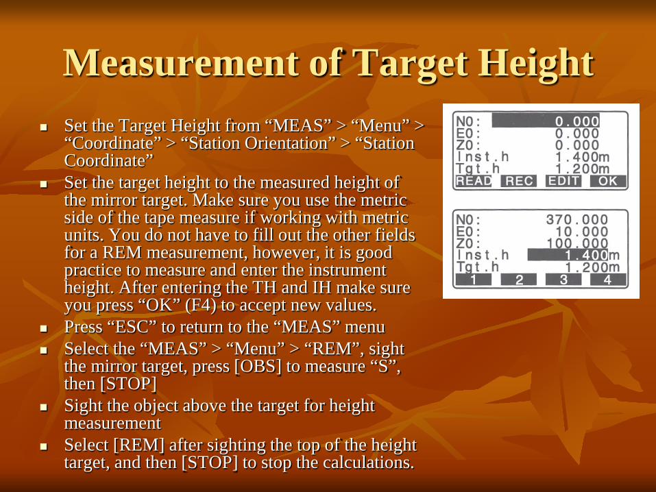
Measurement of Target Height Set the Target Height from “MEAS” > “Menu” >
“Coordinate” > “Station Orientation” > “Station Coordinate”
Set the target height to the measured height of the mirror target. Make sure you use the metric side of the tape measure if working with metric units. You do not have to fill out the other fields for a REM measurement, however, it is good practice to measure and enter the instrument height. After entering the TH and IH make sure you press “OK” (F4) to accept new values.
Press “ESC” to return to the “MEAS” menu Select the “MEAS” > “Menu” > “REM”, sight
the mirror target, press [OBS] to measure “S”, then [STOP]
Sight the object above the target for height measurement
Select [REM] after sighting the top of the height target, and then [STOP] to stop the calculations.

REM Screen Results To re-shoot the mirror
target use the [OBS] on the REM screen.
Note that after selecting REM the instrument continues to make calculations in case you need to adjust the vertical angle on the height target.
Select “STOP” to terminate calculations on the REM command.

Trouble-Shooting the REM Measurement
The only numerical input is the target height so make sure that is entered correctly. When TH is changed make sure you hit the “OK” function key.
If the instrument is reset (zeroed) TH will be 0.0 so if you make a REM measurement with TH=0 the answer will be underestimated by the actual TH.
A quick check can be made by using REM on the mirror target – the answer should be the TH.
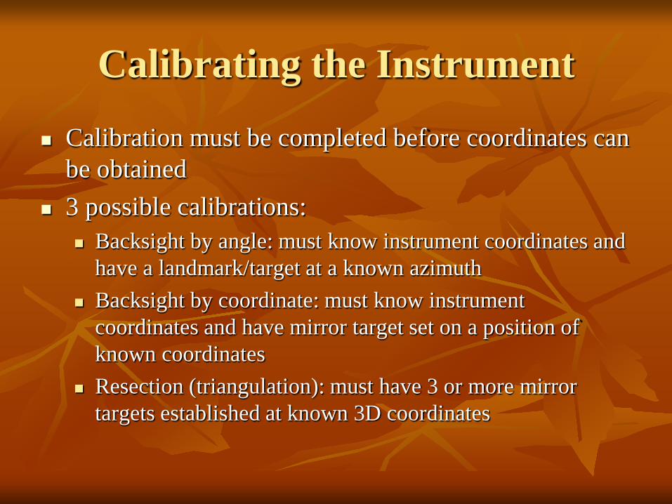
Calibrating the Instrument
Calibration must be completed before coordinates can be obtained
3 possible calibrations: Backsight by angle: must know instrument coordinates and
have a landmark/target at a known azimuth Backsight by coordinate: must know instrument
coordinates and have mirror target set on a position of known coordinates
Resection (triangulation): must have 3 or more mirror targets established at known 3D coordinates
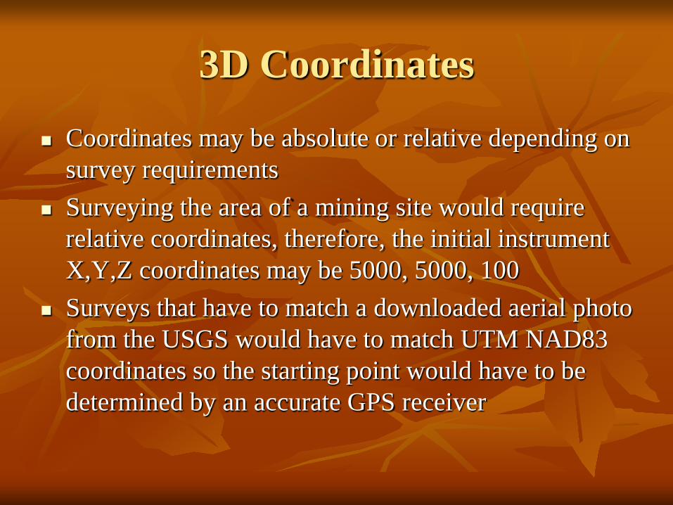
3D Coordinates
Coordinates may be absolute or relative depending on survey requirements
Surveying the area of a mining site would require relative coordinates, therefore, the initial instrument X,Y,Z coordinates may be 5000, 5000, 100
Surveys that have to match a downloaded aerial photo from the USGS would have to match UTM NAD83 coordinates so the starting point would have to be determined by an accurate GPS receiver

Calibrate by Backsight by Angle
Remember that when the instrument is powered on it has a random X,Y coordinate system: you must align the instrument with your working coordinate system.
Level the instrument on the desired starting survey marker. Make sure that on the last leveling step the optical plummet is centered on the survey point
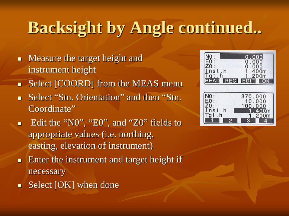
Backsight by Angle continued.. Measure the target height and
instrument height Select [COORD] from the MEAS menu Select “Stn. Orientation” and then “Stn.
Coordinate” Edit the “N0”, “E0”, and “Z0” fields to
appropriate values (i.e. northing, easting, elevation of instrument)
Enter the instrument and target height if necessary
Select [OK] when done
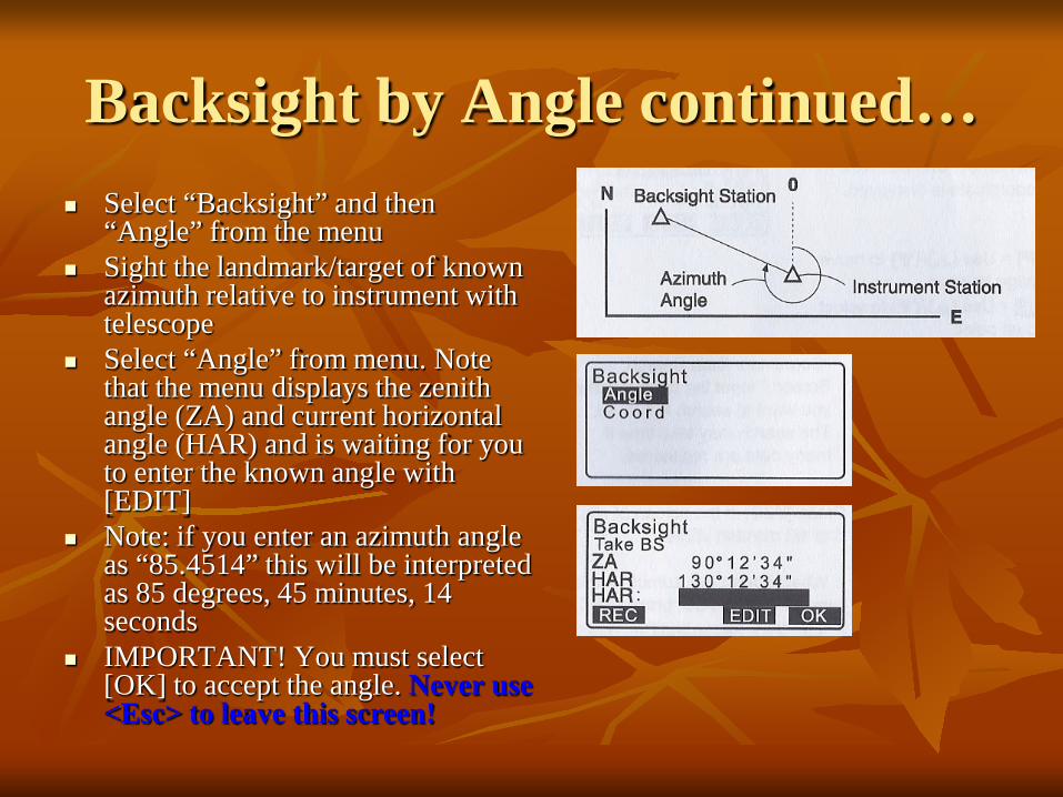
Backsight by Angle continued… Select “Backsight” and then
“Angle” from the menu Sight the landmark/target of known
azimuth relative to instrument with telescope
Select “Angle” from menu. Note that the menu displays the zenith angle (ZA) and current horizontal angle (HAR) and is waiting for you to enter the known angle with [EDIT]
Note: if you enter an azimuth angle as “85.4514” this will be interpreted as 85 degrees, 45 minutes, 14 seconds
IMPORTANT! You must select [OK] to accept the angle. Never use <Esc> to leave this screen!
Backsight by Angle Continued…
NOTE: because the backsight by angle simply sets the instrument horizontal angle encoder to match your desired coordinate system the mirror target is never “shot” by the beam. If you can accurately sight on an object or landmark such as a building corner the mirror target is not needed. Make sure the instrument is “locked” and accurately sighted with telescope before entering the backsight angle.
Backsight by Angle cont…
Because there is no internal statistical measure of how well the backsight angle has been set it is imperative to check the backsight independently: Known point: shoot the target at a position of
known X,Y,Z such as a GPS point. The result should be within the resolution of the GPS.
Known angle: shoot to a landmark at a known azimuth from the instrument location- the angle should be within the resolution of the instrument

Backsight by Coordinate Use this method when you have 2
known survey points with the instrument established on one and the mirror target on the other survey point
From the “MEAS” menu select [COORD] and then “Stn. Orientation”. Set the instrument coordinates with “Stn. Coordinate” and then select [OK] and return to “Backsight”
Select “Coord” and then enter the backsight target coordinates (NBS, EBS, ZBS) and select [OK]
Sight in the target and inspect the “Azmth” (it should be reasonable for your coordinate system).
Select [YES] to calibrate. If you don’t select [YES] the coordinate system is still random
Backsight by coordinate …
Always check the calibration of the instrument by shooting the target used for the backsight.
The resulting X,Y,Z should be within the several cm resolution typical for a TS instrument.
It is a very good idea to shoot other benchmarks within range to make sure accuracy is within acceptable limits
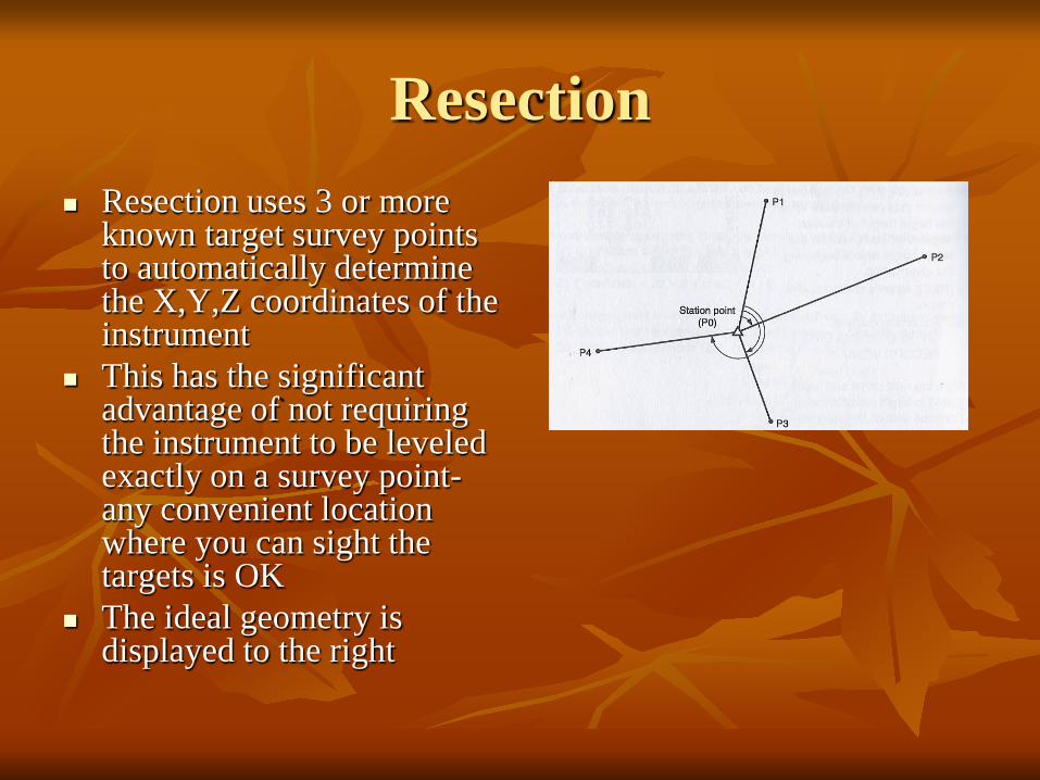
Resection Resection uses 3 or more
known target survey points to automatically determine the X,Y,Z coordinates of the instrument
This has the significant advantage of not requiring the instrument to be leveled exactly on a survey point- any convenient location where you can sight the targets is OK
The ideal geometry is displayed to the right
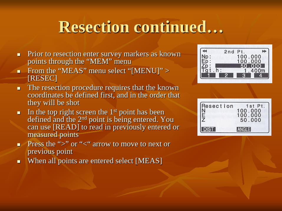
Resection continued… Prior to resection enter survey markers as known
points through the “MEM” menu From the “MEAS” menu select “[MENU]” >
[RESEC] The resection procedure requires that the known
coordinates be defined first, and in the order that they will be shot
In the top right screen the 1st point has been defined and the 2nd point is being entered. You can use [READ] to read in previously entered or measured points
Press the “>” or “<“ arrow to move to next or previous point
When all points are entered select [MEAS]

Resection continued… The [MEAS] screen (right)
displays the point being shot – in this example the 1st point
Choose [DIST] if you are shooting to a mirror target, [ANGLE] if not
Select [YES] to accept measurement, [NO] to re-shoot, [EDIT] to change target height
The [CALC] option will be displayed when the standard deviation of northing and easting can be displayed
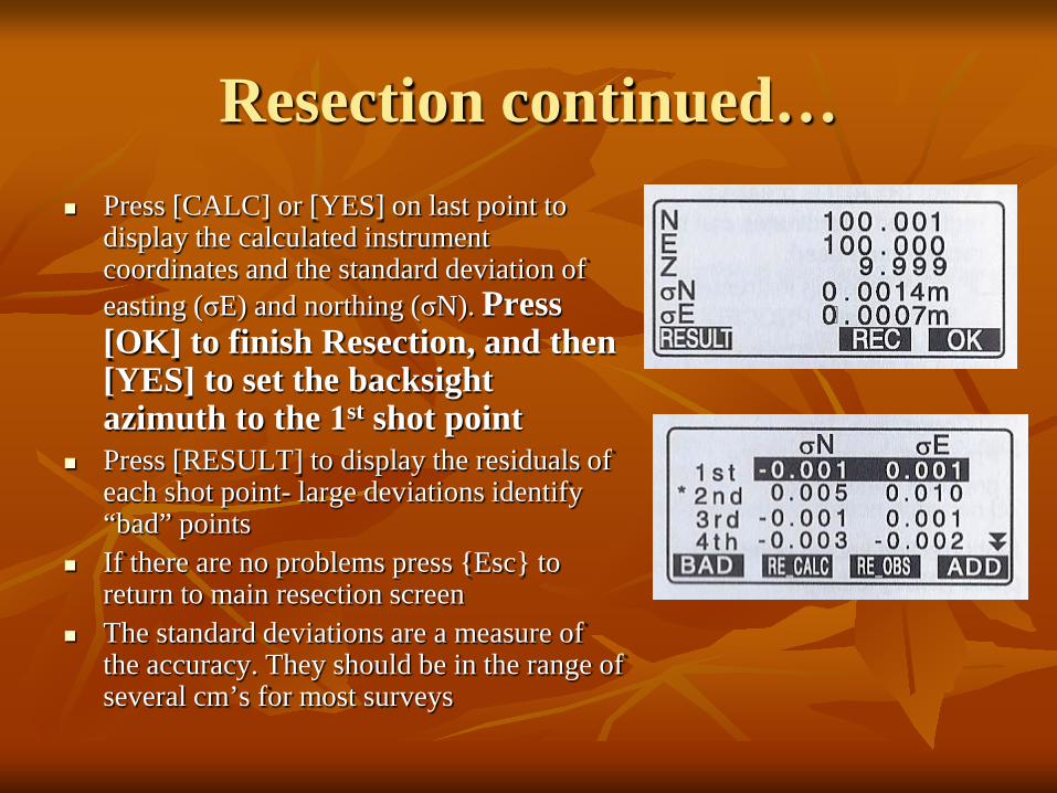
Resection continued… Press [CALC] or [YES] on last point to
display the calculated instrument coordinates and the standard deviation of easting (σE) and northing (σN). Press [OK] to finish Resection, and then [YES] to set the backsight azimuth to the 1st shot point
Press [RESULT] to display the residuals of each shot point- large deviations identify “bad” points
If there are no problems press {Esc} to return to main resection screen
The standard deviations are a measure of the accuracy. They should be in the range of several cm’s for most surveys

Resection Notes Resection initializes the X,Y,Z coordinates of the
instrument. Save this as a point (ex. G1S02 for group 2, instrument station #2) since it represents a surveyed coordinate
Once the instrument is calibrated the mirror targets can be taken down and used elsewhere
The instrument height should be entered before resection is calculated
You can only begin shooting resection point 1 from the resection point #3 or higher coordinate entry screen
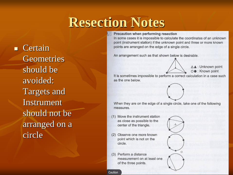
Resection Notes
Certain Geometries should be avoided: Targets and Instrument should not be arranged on a circle
Coordinate Measurement
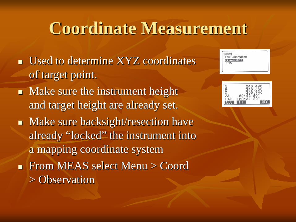
Used to determine XYZ coordinates of target point.
Make sure the instrument height and target height are already set.
Make sure backsight/resection have already “locked” the instrument into a mapping coordinate system
From MEAS select Menu > Coord > Observation
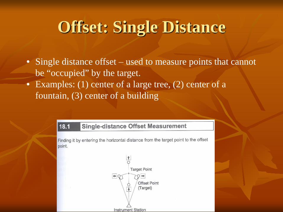
Offset: Single Distance
• Single distance offset – used to measure points that cannot be “occupied” by the target.
• Examples: (1) center of a large tree, (2) center of a fountain, (3) center of a building
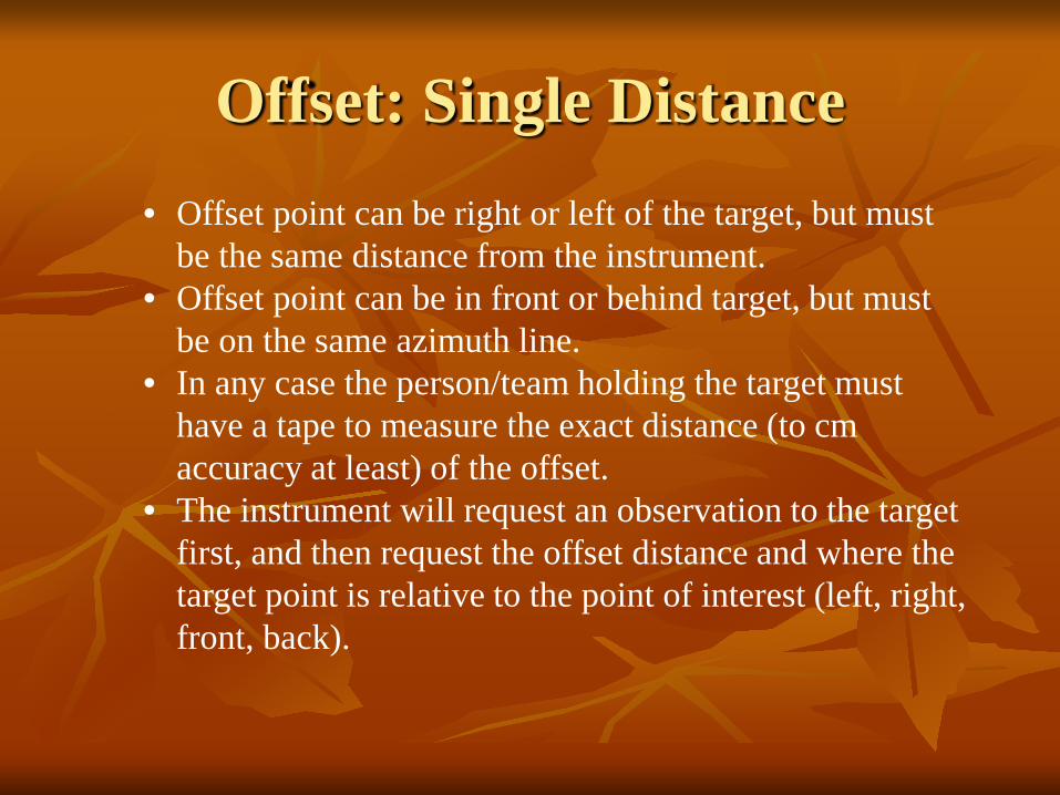
Offset: Single Distance • Offset point can be right or left of the target, but must
be the same distance from the instrument. • Offset point can be in front or behind target, but must
be on the same azimuth line. • In any case the person/team holding the target must
have a tape to measure the exact distance (to cm accuracy at least) of the offset.
• The instrument will request an observation to the target first, and then request the offset distance and where the target point is relative to the point of interest (left, right, front, back).
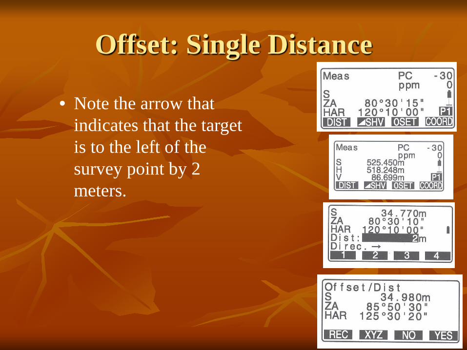
Offset: Single Distance
• Note the arrow that indicates that the target is to the left of the survey point by 2 meters.