touch encoder - docs.microsoft.com
TRANSCRIPT

Questions? Please contact [email protected] Bulletin 1295 Rev 04/19
Interface Control Document (CANBUS J1939 Protocol) TE OS Version 1.0.0 or greater (includes UtilityApp)
Touch Encoder

Questions? Please contact [email protected] Bulletin 1295 Rev 04/19
Revision History
Revision Date Description
A 2/19/2018 Original Release
B 2/27/2018 Changes to the example message in section 2.5.2 Rephrased the meaning of Byte 7 in section 2.5.2
C 3/6/2018 Changed Byte message in section 3.1
D 07/25/2018 Changed pinout on M12 to reflect production pinout
E 8/24/2018 Added Programming Harness Information
F 10/25/2018 Updated Run/Programming Mode Schematics
G 12/7/2018 Updated Touch Encoder Image
H 2/12/2019 Added Command, Multi-value, and Display Code Information

Questions? Please contact [email protected] Bulletin 1295 Rev 04/19
Table of Contents
1. Overview .......................................................................................................................................................... 4 1.1 Reference Documents ............................................................................................................................. 4 1.2 Programmable Features (Coming Soon) ................................................................................................ 4
2. J1939 Communications.................................................................................................................................... 5 2.1 Message Header Description .................................................................................................................. 5 2.2 J1939 Bitfield Location and Byte Ordering .............................................................................................. 6 2.3 Grayhill Touch Encoder Source Address ................................................................................................ 6 2.4 Physical Layer ......................................................................................................................................... 6 2.5 Standard Messages ................................................................................................................................ 7
3. Configuration and Control Commands ........................................................................................................... 10 3.1 Modify Widget Data 17 (0x11) ........................................................................................................... 10 3.2 Modify Events Data PGN 209 (0xD1) ................................................................................................ 12 3.3 Modify Events Data Priority 210 (0xD2) ............................................................................................. 12 3.4 Modify Events Data Transmission Period 211 (0xD3) ......................................................................... 13 3.5 Modify Widgets Data PGN 217 (0xD9) .............................................................................................. 13 3.6 Modify Widgets Data Priority 218 (0xDA) ........................................................................................... 13 3.7 Modify Widgets Data Transmission Period 219 (0xDB) ........................................................................ 14 3.8 Modify Source Address 224 (0xE0) ................................................................................................... 14 3.9 Backlight Intensity ................................................................................................................................. 14 3.10 Changing J1939 NAME Fields (COMING SOON) 228 (0xE4) ............................................................. 15 3.11 Change ECUID Command (COMING SOON) 229 (0xE5) ................................................................. 15 3.12 Change ECUID Field Data (COMING SOON) 230 (0xE6) ................................................................ 16
4. Other J1939 Commands ................................................................................................................................ 16 4.1.1 Address Claimed (COMING SOON) ..................................................................................................... 16 4.1.2 PGN Request (COMING SOON) .......................................................................................................... 17 4.1.2.1 ECU Identification Information (COMING SOON) ............................................................................. 17 4.1.2.2 Software Identification (COMING SOON) ......................................................................................... 18 4.1.3 Acknowledgement Message (COMING SOON) ................................................................................... 19
5. Appendix ........................................................................................................................................................ 20 5.1 Programming Harness .......................................................................................................................... 20

Questions? Please contact [email protected] Bulletin 1295 Rev 04/19
1. Overview This document describes the functionality and communication of the Grayhill Touch Encoder product.
1.1 Reference Documents The following documents are referenced within this document.
1. SAE-J1939 2. SAE-J1939/11 3. SAE-J1939/21 4. SAE-J1939/71 5. SAE-J1939/81
1.2 Programmable Features (Coming Soon) The following fields can be configured by Grayhill prior to leaving the factory. Requests for custom configuration will be captured in the top-level CAD drawing
Field Name Parameter Type Size (bytes) Range Default
Value Comments
ECUID_PN ASCII CHARS 64 ERASED Per SAE-J1939/71
ECUID_LOC ASCII CHARS 64 ERASED Per SAE-J1939/72
ECUID_TYPE ASCII CHARS 64 ERASED Per SAE-J1939/73
J1939_NAME_ECU_INSTANCE INTEGER 3 bits 0 - 7 0 Section 3.6 J1939_NAME_FUNCTION_INSTANCE INTEGER 5 bits 0 - 31 0 Section 3.6
J1939_NAME_FUNCTION INTEGER 8 bits 0 - 255 135 Per SAE-J1939 Base Spec Appx B
J1939_VEHICLE_SYSTEM INTEGER 7 bits 0 - 127 0 Per SAE-J1939 Base Spec Appx B
J1939_VEHICLE_SYSTEM_INSTANCE INTEGER 4 bits 0 - 15 0 Section 3.6
J1939_NAME_INDUSTRY_GROUP INTEGER 3 bits 0 - 7 0 Per SAE-J1939 Base Spec Appx B
J1939_NAME_ARBITRARY_ADDRESS_CAPABLE INTEGER 1 bit 0 - 1 0 Per SAE-J1939/81
J1939_SOURCE_ADDRESS BYTE 1 0 - 254 242 (F2H) Per SAE-J1939 Base Spec
EVENT_DATA_PGN 2 0-65538 65295 (FF0FH) Section 3.2
EVENT_DATA_PRI 2 0-7 6 Section 3.3
EVENT_DATA_SOE (Send On Event) 1 0-1 1 Section 3.4
EVENT_DATA_TX_PER 1 0-254 0 Section 3.4
WIDGETS_DATA_PGN 2 0-65538 65297 (FF11H) Section 3.5
WIDGETS_DATA_PRI 2 0-7 6 Section 3.6
WIDGETS_DATA_SOE (Send On Event) 1 0-1 1 Section 3.7
WIDGETS_DATA_TX_PER 1 0-254 0 Section 3.7

Questions? Please contact [email protected] Bulletin 1295 Rev 04/19
2. J1939 Communications 2.1 Message Header Description
Figure 1 illustrates the format of the CAN message ID. A brief description of each field follows. D
ata
Page
Res
erve
d
Priority PDU Format (PF) PDU Specific (PS) Source Address
Figure 1
2.1.1 Priority This 3-bit field is used to define the priority during arbitration. ‘000’ is the highest priority and is usually associated with high-speed control messages. Low priority is used for non-critical configuration and information messages.
2.1.2 DP (Data Page) This 1-bit field defines on which data page (0 or 1) the message is defined in the J1939 specification. Page 0 contains the messages that are presently defined, while Page 1 is for future expansion according to J1939.
2.1.3 Protocol Data Unit (PDU) - PDU Format (PF) This 8-bit field determines the format of the message and is one of the fields which determine the Parameter Group Number of the message (see 2.1.6). If the value is between 0 and 239, the message is a PDU 1 Format message. These messages are sent to specific addresses.
2.1.4 Protocol Data Unit (PDU) - PDU Specific (PS) The PDU Specific (PS) field is the Destination Address (DA). If the value is between 240 and 255, the message is a PDU 2 Format message. These messages are not sent to a specific address, but are instead broadcasted to the entire network. The PS then becomes the Group Extension (GE) field.
2.1.5 Source Address This 8-bit field is the source address of the device that sent the message.
2.1.6 Parameter Group Number J1939 defines allowable messages by their Parameter Group Number (PGN). The Parameter Group Number is a 3-byte value that uniquely defines the message purpose. A PGN has the following format: If the PDU Format value for a message is less than 240, then the last 8 bits of the PGN are set to ‘0’. The specification gives the decimal equivalent of the PGNs. To obtain the PF and PS values to use for a specific message, convert the decimal value from the specification to hexadecimal and use the last two bytes. These values can then be used to either send messages on the network or to request messages from other source addresses.
Questions? Please contact [email protected] Bulletin 1295 Rev 04/19
2.2 J1939 Bitfield Location and Byte Ordering The byte and bit ordering and location within the data field are per the J1939 specification. The first data byte is sent first and is referenced as Byte 1. The LSB of the data bytes are on the right and are referenced as Bit 1.
The convention used to locate a parameter in the data field is the same as specified in SAE-J1939/71. The format used is “R.x” where R is the byte number and x is the starting bit number within the byte. The length is the number of bits starting at this point.
Example 1: Location 4.3 with a length of 3 bits would have the value of 1 as illustrated below.
Byte 4 = 0x67 = 0b01100111. The bold value is the three bit field holding a value of 0b001.
Example 2: Location 4.3 with a length of 3 bits would have the value of 6 as illustrated below.
Byte 4 = 0x7b = 0b01111011. The bold value is the three bit field holding a value of 0b110.
2.3 Grayhill Touch Encoder Source Address The source address of the Grayhill Touch Encoder device is set to 242 (0xF2) at the factory. This may be modified dynamically if Dynamic Addressing is turned on, with the Commanded Address message in accordance with J1939-81, or with the proprietary Source Address Command. The source address value is stored in non-volatile memory. The ability to change the source address will allow multiple Touch Encoder devices to coexist in the same system.
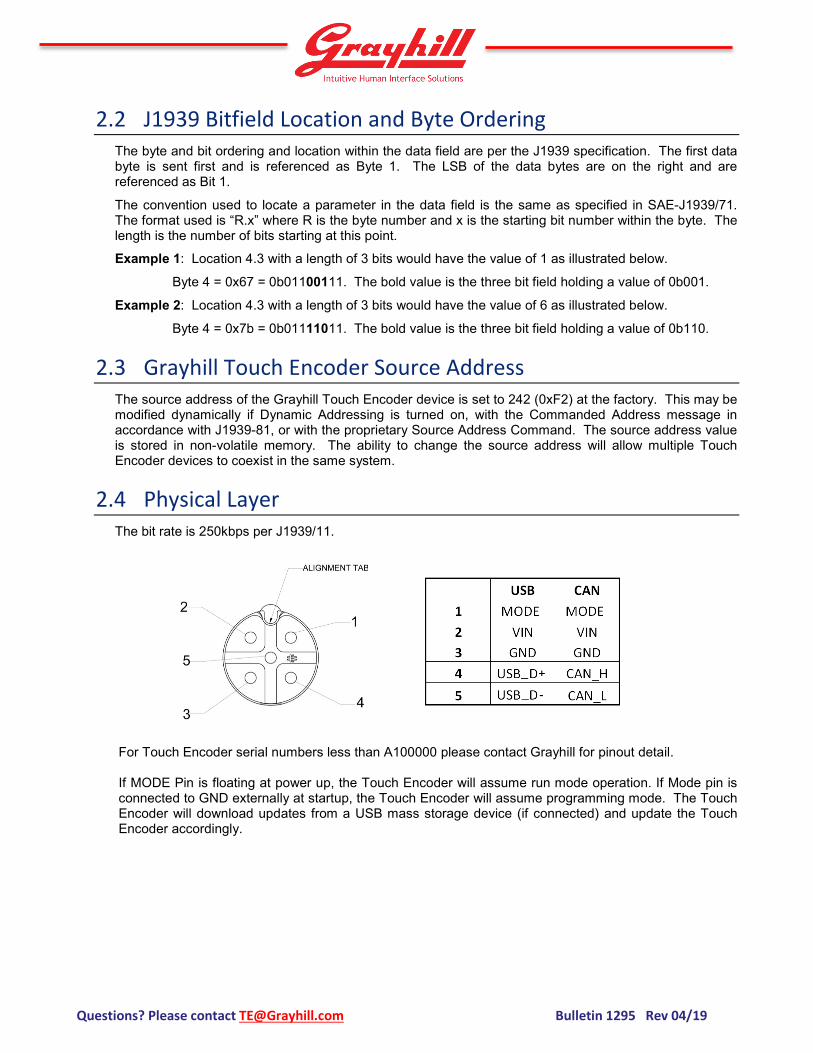
2.4 Physical Layer The bit rate is 250kbps per J1939/11.
For Touch Encoder serial numbers less than A100000 please contact Grayhill for pinout detail. If MODE Pin is floating at power up, the Touch Encoder will assume run mode operation. If Mode pin is connected to GND externally at startup, the Touch Encoder will assume programming mode. The Touch Encoder will download updates from a USB mass storage device (if connected) and update the Touch Encoder accordingly.

Questions? Please contact [email protected] Bulletin 1295 Rev 04/19
Run Mode: Programming Mode: Note: Load files to FLASH drive and plug into socket. Touch Encoder only samples the MODE pin during power up, so be sure this occurs after connecting the harness and FLASH drive.
2.5 Standard Messages The Events Data message and the Widget Data message all use the Proprietary B PDU2 format (PF = 255) that broadcasts to no specific address the status of the device. The Control Data message uses Proprietary A PDU1 format (PF = 239).
2.5.1 Events Data Message Priority – 0b110 (6) R/DP – 0b00 (0) PF – 0xFF (255), Proprietary B PDU2 Format GrpExt – 0x0F (15) SrcAddr – 0xF2 (242), i.e. Touch Encoder default source address ID – 0x18FF0FF2 Direction - Transmit Data Length – 8 bytes Transmission Rate – On Event (programmable) *The Events Data PGN can be reassigned using a configuration command.
See previous page: Connector Pinouts
See previous page: Connector Pinouts
Recommended Flash Drives: Verbatim 49304 SanDisk SDCZ60-016G-B35

Questions? Please contact [email protected] Bulletin 1295 Rev 04/19
Start Length Desc. Values 1.1 8 bits Screen
Number 0x01 – Screen #1 at the time of event … 0xFF – Screen #255 at the time of event
2.1 8 bits Reserved Reserved for future use 3.1 8 bits Event ID 0x01- Events: Standard (Relative Encoder, Taps,
Swipes) 4.1 8 bits Encoder
(relative) 0x80 – No Change 0x81 – Clockwise 1 detent 0x82 – Clockwise 2 detents … 0xFE – Clockwise 126 detents 0x7F – Counter-Clockwise 1 detent 0x7E – Counter-Clockwise 2 detents … 0x01 – Counter-Clockwise 127 detents 0x00 – Not used 0xFF – Not used
5.1 16 bits Tap Mask 0x0000 – No Tap detected 0x0001 – Tap in Zone 1 detected 0x0002 – Tap in Zone 2 detected 0x0004 – Tap in Zone 3 detected … 0x4000 – Tap in Zone 15 detected 0x8000 – Tap on screen (anywhere) detected
7.1 8 bits Swipe Mask 0x00 – No Swipe detected 0x01 – Swipe Up detected 0x02 – Swipe Down detected 0x03 – Swipe Left detected 0x04 – Swipe Right detected 0x80 – Swipe (any direction) detected
The Events Data message is sent to inform the receiving (host) ECU of any new encoder, tap or swipe events that occurred on the Touch Encoder device. If such an event causes a new screen to be displayed or if any of the Value IDs on the current screen were changed, the event is followed by a Widget Data message or messages which, on a screen change, will communicate the data in all Value IDs on the new screen.
Example: Turning the encoder counter-clockwise by 2 detents on screen 1 (since last message) will result in the following message being transmitted.
ID=0x18FF0FF2, LEN=8, DATA=0x01,0x00,0x01,0x7E,0x00,0x00,0x00,0xFF
Example: Swiping up on the touch pad on screen 5 will result in the following message being transmitted.
ID=0x18FF0FF2, LEN=8, DATA=0x05,0x00,0x01,0x80,0x00,0x00,0x81,0xFF
Example: Tapping in screen 10 zone 4 of the touch pad will result in the following message being transmitted.
ID=0x18FF0FF2, LEN=8, DATA=0x0A,0x00,0x01,0x80,0x80,0x08,0x00,0xFF
2.5.2 Widget Data Message
Questions? Please contact [email protected] Bulletin 1295 Rev 04/19
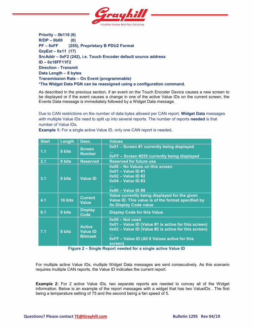
Priority – 0b110 (6) R/DP – 0b00 (0) PF – 0xFF (255), Proprietary B PDU2 Format GrpExt – 0x11 (17) SrcAddr – 0xF2 (242), i.e. Touch Encoder default source address ID – 0x18FF11F2 Direction - Transmit Data Length – 8 bytes Transmission Rate – On Event (programmable) *The Widget Data PGN can be reassigned using a configuration command.
As described in the previous section, if an event on the Touch Encoder Device causes a new screen to be displayed or if the event causes a change in one of the active Value IDs on the current screen, the Events Data message is immediately followed by a Widget Data message.
Due to CAN restrictions on the number of data bytes allowed per CAN report, Widget Data messages with multiple Value IDs need to split up into several reports. The number of reports needed is that number of Value IDs. Example 1: For a single active Value ID, only one CAN report is needed. Start Length Desc. Values
1.1 8 bits Screen Number
0x01 – Screen #1 currently being displayed … 0xFF – Screen #255 currently being displayed
2.1 8 bits Reserved Reserved for future use
3.1 8 bits Value ID
0x00 – No Values on this screen 0x01 – Value ID #1 0x02 – Value ID #2 0x04 – Value ID #3 … 0x80 – Value ID #8
4.1 16 bits Current Value
Value currently being displayed for the given Value ID. This value is of the format specified by its Display Code value
6.1 8 bits Display Code Display Code for this Value
7.1 8 bits Active Value ID Bitmask
0x00 – Not used 0x01 – Value ID (Value #1 is active for this screen) 0x02 – Value ID (Value #2 is active for this screen) … 0xFF – Value ID (All 8 Values active for this screen)
Figure 2 – Single Report needed for a single active Value ID
For multiple active Value IDs, multiple Widget Data messages are sent consecutively. As this scenario requires multiple CAN reports, the Value ID indicates the current report.
Example 2: For 2 active Value IDs, two separate reports are needed to convey all of the Widget information. Below is an example of the report messages with a widget that has two ValueIDs . The first being a temperature setting of 75 and the second being a fan speed of 5.

Questions? Please contact [email protected] Bulletin 1295 Rev 04/19
ID=0x18FF11F2, LEN=8, DATA=0x01,0x00,0x01,0x4B,0x00,0x00,0x03,0xFF
ID=0x18FF11F2, LEN=8, DATA=0x01,0x00,0x02,0x05,0x00,0x00,0x03,0xFF
2.5.3 Configuration and Control Message
Priority – 0b110 (6) R/DP – 0b00 (0) PF – 0xEF (239) Proprietary A PDU1 Format PS – DestAddr, i.e. address of the Touch Encoder device, default value: 242 (0xF2) SrcAddr – 0x21 (33), i.e. example source address ID – 0x18EFF221 Direction - Receive Data Length – 8 Start Length Desc. Values
1.1 1 Byte Configuration and Control Command Command Byte as described in Sec. 3
2.1 7 Bytes Configuration and Control Data Variable as described in Sec. 3
3. Configuration and Control Commands
Changing of the configuration and how the Touch Encoder device behaves is done with the Configuration and Control message described in Sec 2.5.3. The first byte serves as the command byte. Where applicable, changes take effect immediately and are stored in non-volatile memory unless otherwise noted.
Note that some commands will only take effect if sent from a source address of 249 (0xF9). For all other commands, the following examples will assume a source address of 33 (0x21).
The header information for these commands is as follows:
Priority – 0b110 (6) R/DP – 0b00 (0) PF – 0xEF (239) PS – DestAddr, i.e. address of the Touch Encoder device, default value: 0xF2 (242) SrcAddr – 0x21 (33), i.e. example source address ID – 0x18EFF221, Proprietary A PDU1 Format Direction - Receive
3.1 Modify Widget Data 17 (0x11) Data Length – 7 bytes

Questions? Please contact [email protected] Bulletin 1295 Rev 04/19
Start Length Desc. Values 1.1 8 bits Command 0x11 – Force Widget Data
2.1 8 bits Screen
Number 0x00 – Screen #0 to be displayed 0x01 – Screen #1 to be displayed … 0xFF – Screen #255 to be displayed
3.1 8 bits Value ID 0x00 – No altered Values 0x01 – Value ID #1 0x02 – Value ID #2 0x04 – Value ID #3 … 0x80 – ValueID #8
4.1 16 bits Current Value Value to be displayed. This value is of the format specified by Display Code value
6.1 8 bits Display Code Display Code for this Value 7.1 8 bits Active Value
ID Bitmask 0x00 – Not used 0x01 – Value #1 currently active 0x02 – Value #2 currently active … 0x80 – All 8 Values currently active
Example: Sending the following message to a Touch Encoder device having the default address of 0xF2 will set the current screen to be displayed to 0x03 and the current value of ValueID #2 of that screen to 0x01F4. .
ID=18EFF221, LEN=8, Data=0x11, 0x03, 0x02, 0xF4, 0x01, 0x00,0x02, 0xFF
3.1.1 Multi-Value Data Example
Example: The figure above displays an example of a multi-value widget. The dynamic text object is designated at Value ID #2. The lighted icon object is designated as Value ID #3. Below is the sequence of messages to turn
Dynamic Text Object Value ID #2
Lighted Icon Object Value ID #3

Questions? Please contact [email protected] Bulletin 1295 Rev 04/19
on the top lighted icon and change the dynamic text to 100. Note that the lighted icon object has an offset of 0x8000
ID=18EFF221, LEN=8, Data=0x11, 0x03, 0x04, 0x01, 0x80, 0x00, 0x06, 0xFF
ID=18EFF221, LEN=8, Data=0x11, 0x03, 0x02, 0x64, 0x00, 0x00, 0x06, 0xFF 3.1.2 Display Code Display Code gives the Touch Encoder the ability to display decimal numbers. The Display Code is one byte in length, with the upper four bits being the decimal code and the lower 4 bits reserved for future use. The decimal code is a signed four bit integer. The table below describes how the decimal code works
Display Code Byte 0x0X Default integer number 0x1X Integer x 10 e.g. 10=100 0x2X Integer x 100 e.g. 10=1000 0xEX Integer ÷ 100 e.g. 10=0.10 0xFX Integer ÷ 10 e.g. 10=1.0
3.2 Modify Events Data PGN 209 (0xD1) Data Length – 8 bytes
Byte 1 Byte 2 Byte 3 Byte 4 Byte 5 Byte 6 Byte 7 Byte 8 0xD1 aa bb xx xx xx 0x55 0xAA
aa – The least significant byte of the new PGN. Valid Range: 0..255 bb - The most significant byte of the new PGN. Valid Range: 0..255 xx – Don’t Care. Should be 0xFF following J1939 convention 0x55 – Low byte of 16 bit key 0xAA – High byte of 16 bit key
3.3 Modify Events Data Priority 210 (0xD2) Data Length – 8 bytes

Questions? Please contact [email protected] Bulletin 1295 Rev 04/19
Byte 1 Byte 2 Byte 3 Byte 4 Byte 5 Byte 6 Byte 7 Byte 8 0xD2 dd xx xx xx xx 0x55 0xAA
dd – The new priority. Valid Range: 0..7 xx – Don’t Care. Should be 0xFF following J1939 convention 0x55 – Low byte of 16 bit key 0xAA – High byte of 16 bit key
3.4 Modify Events Data Transmission Period 211 (0xD3) Data Length – 8 bytes
dd – The value multiplied by 10ms. Valid range: 1..255 yielding between 10ms to 2.54 seconds. A value
of zero automatically assumes transmit upon event. Event – Valid settings is 0 or 1. A value of one sends the key message upon change in key information.
Upon transmission the timer is reset. A value of zero will cause the message to be transmitted only at the specified time interval.
xx – Don’t Care. Should be 0xFF following J1939 convention 0x55 – Low byte of 16 bit key 0xAA – High byte of 16 bit key
3.5 Modify Widgets Data PGN 217 (0xD9) Data Length – 8 bytes Byte 1 Byte 2 Byte 3 Byte 4 Byte 5 Byte 6 Byte 7 Byte 8
0xD9 aa bb xx xx xx 0x55 0xAA
aa – The least significant byte of the new PGN. Valid Range: 0..255 bb - The most significant byte of the new PGN. Valid Range: 0..255 xx – Don’t Care. Should be 0xFF following J1939 convention 0x55 – Low byte of 16 bit key 0xAA – High byte of 16 bit key
3.6 Modify Widgets Data Priority 218 (0xDA) Data Length – 8 bytes
Byte 1 Byte 2 Byte 3 Byte 4 Byte 5 Byte 6 Byte 7 Byte 8
0xD3 dd Event xx xx xx 0x55 0xAA
Questions? Please contact [email protected] Bulletin 1295 Rev 04/19
Byte 1 Byte 2 Byte 3 Byte 4 Byte 5 Byte 6 Byte 7 Byte 8
0xDA dd xx xx xx xx 0x55 0xAA
dd – The new priority. Valid Range: 0..7 xx – Don’t Care. Should be 0xFF following J1939 convention 0x55 – Low byte of 16 bit key 0xAA – High byte of 16 bit key
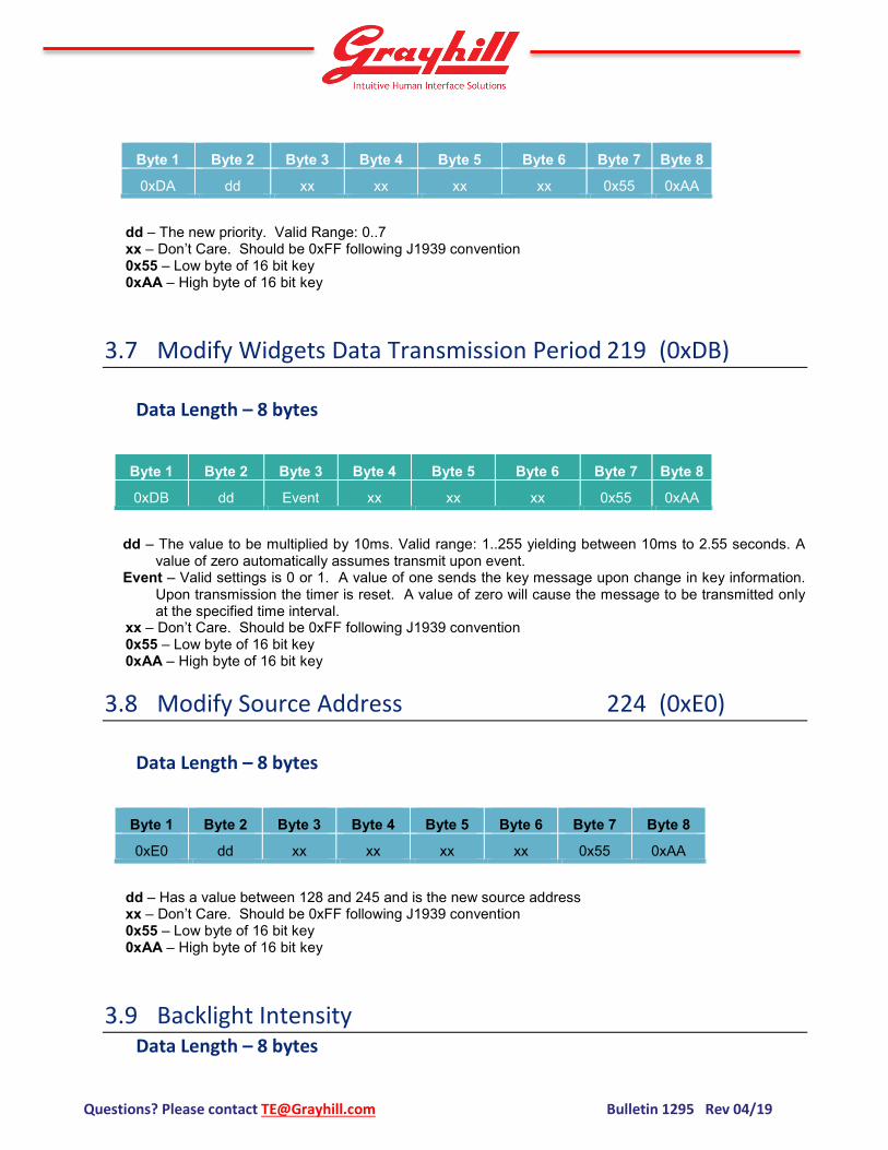
3.7 Modify Widgets Data Transmission Period 219 (0xDB) Data Length – 8 bytes
Byte 1 Byte 2 Byte 3 Byte 4 Byte 5 Byte 6 Byte 7 Byte 8
0xDB dd Event xx xx xx 0x55 0xAA
dd – The value to be multiplied by 10ms. Valid range: 1..255 yielding between 10ms to 2.55 seconds. A
value of zero automatically assumes transmit upon event. Event – Valid settings is 0 or 1. A value of one sends the key message upon change in key information.
Upon transmission the timer is reset. A value of zero will cause the message to be transmitted only at the specified time interval.
xx – Don’t Care. Should be 0xFF following J1939 convention 0x55 – Low byte of 16 bit key 0xAA – High byte of 16 bit key
3.8 Modify Source Address 224 (0xE0) Data Length – 8 bytes
Byte 1 Byte 2 Byte 3 Byte 4 Byte 5 Byte 6 Byte 7 Byte 8
0xE0 dd xx xx xx xx 0x55 0xAA
dd – Has a value between 128 and 245 and is the new source address xx – Don’t Care. Should be 0xFF following J1939 convention 0x55 – Low byte of 16 bit key 0xAA – High byte of 16 bit key
3.9 Backlight Intensity Data Length – 8 bytes

Questions? Please contact [email protected] Bulletin 1295 Rev 04/19
Byte 1 Byte 2 Byte 3 Byte 4 Byte 5 Byte 6 Byte 7 Byte 8
0x80 xx dd xx xx xx xx xx
dd – Has a value between 0 and 100 and is the percentage of backlight intensity xx – Don’t Care. Should be 0xFF following J1939 convention
3.10 Changing J1939 NAME Fields (COMING SOON) 228 (0xE4) *Note: Must be sent from source address of 249 (0xF9)
Data Length – 8 bytes Byte 1 Byte 2 Byte 3 Byte 4 Byte 5 Byte 6 Byte 7 Byte 8
0xEA subcmd db0 db1 db2 xx 0x55 0xAA
subcmd – Represents the field within the name to change. db0, db1, db2 – Data bytes associated with the sub command, LSB to MSB respectively. xx – Don’t Care. Should be 0xFF following J1939 convention 0x55 – Low byte of 16 bit key 0xAA – High byte of 16 bit key
Sub Commands
Sub Cmd Field Description
0 ID 21 bits of db0..2
1 ECU Instance Bits 3..1 of Byte 5 (Most Significant at 3)
2 Function Instance Bits 8..4 of Byte 5 (Most Significant at 8)
3 Function Bits 8..1 of Byte 6 (Most Significant at 8)
5 Vehicle System Bits 8..2 of Byte 7 (Most Significant at 8)
4 Vehicle System Instance Bits 4..1 of Byte 8 (Most Significant at 4)
6 Industry Group Bits 7..5 of Byte 8 (Most Significant at 7)
7 Arbitrary Addr. Capable Bit 8 of Byte 8
Refer to J1939 base document for field value ranges and relationships.
3.11 Change ECUID Command (COMING SOON) 229 (0xE5) *Note: Must be sent from source address of 249 (0xF9)
Data Length – 8 bytes

Questions? Please contact [email protected] Bulletin 1295 Rev 04/19
Byte 1 Byte 2 Byte 3 Byte 4 Byte 5 Byte 6 Byte 7 Byte 8 0xEB 0..2 dd xx xx xx 0x55 0xAA
0 – Selects ECUID Part Number to change 1 – Selects ECUID Location to change 2 – Selects ECUID Type to change dd – Number of ASCII characters in the field, max of 64
3.12 Change ECUID Field Data (COMING SOON) 230 (0xE6) *Note: Must be sent from source address of 249 (0xF9)
Data Length – 8 bytes
Byte 1 Byte 2 Byte 3 Byte 4 Byte 5 Byte 6 Byte 7 Byte 8
0xEC 1 to 7 bytes of ASCII Data
* No Key used in bytes 7 and 8
.
4. Other J1939 Commands The following messages are defined in the J1939 documents and are implemented in the Touch Encoder device.
4.1.1 Address Claimed (COMING SOON)
Priority – 0b110 (6) R/DP – 0b00 (0) PF – 0xEE (238), Address Claimed PS – DestAddr, address should always be the Global Address, 0xFF? SrcAddr – 0xF2 (242), i.e. Touch Encoder source address ID – 0x18EEFFF2, Proprietary A PDU1 Format Direction – Transmit Data Length – 8 Transmission Rate – Upon boot or whenever requested
Start Length Desc. Values
1.1 21 Bits Identity Number 0 to 221-1
3.6 11 Bits Manufacturers Code 294 (Assigned to Grayhill by SAE)

Questions? Please contact [email protected] Bulletin 1295 Rev 04/19
5.1 3 Bits ECU Instance 0 (Default)
5.4 5 Bits Function Instance 0 (Default)
6.1 8 Bits Function 135 (Keypad, Default) *
7.1 1 Bit Reserved 0 (Defined by SAE)
7.2 7 Bits Vehicle System 0 (Default) *
8.1 4 Bits Vehicle System Instance 0 (Default)
8.5 3 Bits Industry Group
0 = Global (Default) * 1 = On-Highway Equipment
2 = Agricultural and Forestry Equipment 3 = Construction Equipment
4 = Marine 5 = Industrial-Process Control-
Stationary 6 & 7 = Reserved
8.8 1 Bit Arbitrary Address Capable
0 = Not Capable 1 = Capable (Default)
*Refer to J1939 base document for the Function value based on the Industry Group and Vehicle System combinations
4.1.2 PGN Request (COMING SOON) Priority – 0b110 (6) R/DP – 0b00 (0) PF – 0xEA (234), PGN Request, Proprietary A PDU1 Format PS – DestAddr, address of the Touch Encoder device to respond or the Global Address SrcAddr – 0x21 (33), i.e. example source address ID – 0x18EAF221 Direction - Receive Data Length – 3
Start Length Desc. Values
1.1 1 Byte Byte 1 of PGN being requested (LSB) 0 to 255
2.1 1 Byte Byte 2 of PGN being requested 0 to 255
3.1 1 Byte Byte 3 of PGN being requested (MSB) 0
The following are the supported PGN’s that can be requested from the keypad. If the request is unsupported the keypad responds with a NACK (Refer to J1939-21).
4.1.2.1 ECU Identification Information (COMING SOON)
Priority – 0b110 (6) R/DP – 0b00 (0) PF – 0xFD (253), ECU ID, Proprietary B PDU2 Format
Questions? Please contact [email protected] Bulletin 1295 Rev 04/19
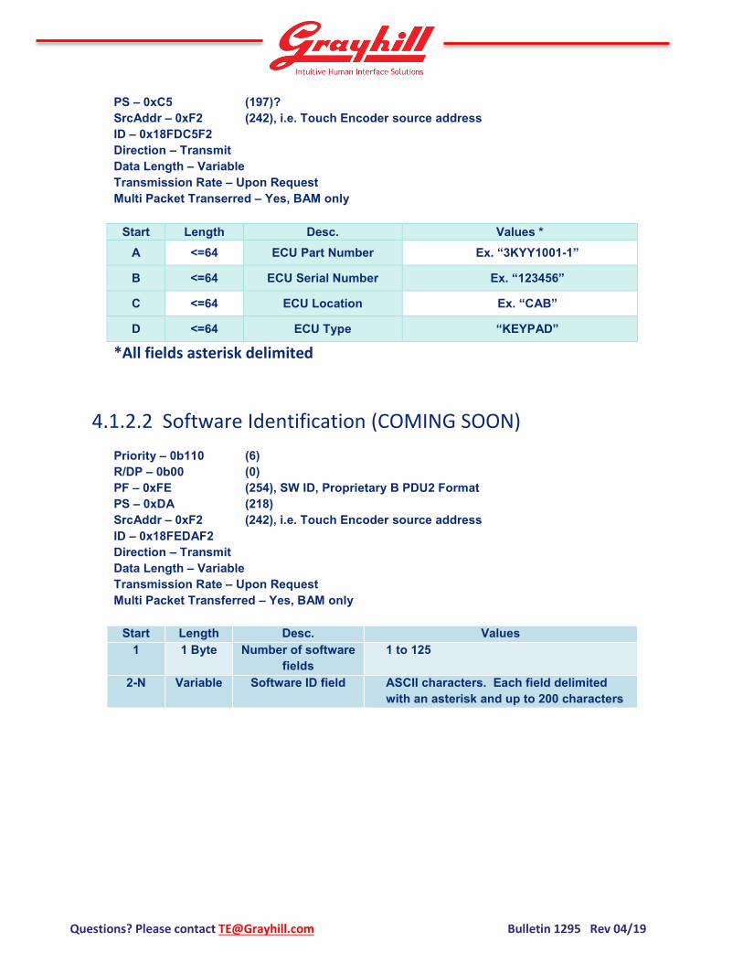
PS – 0xC5 (197)? SrcAddr – 0xF2 (242), i.e. Touch Encoder source address ID – 0x18FDC5F2 Direction – Transmit Data Length – Variable Transmission Rate – Upon Request Multi Packet Transerred – Yes, BAM only
Start Length Desc. Values * A <=64 ECU Part Number Ex. “3KYY1001-1”
B <=64 ECU Serial Number Ex. “123456”
C <=64 ECU Location Ex. “CAB”
D <=64 ECU Type “KEYPAD”
*All fields asterisk delimited
4.1.2.2 Software Identification (COMING SOON) Priority – 0b110 (6) R/DP – 0b00 (0) PF – 0xFE (254), SW ID, Proprietary B PDU2 Format PS – 0xDA (218) SrcAddr – 0xF2 (242), i.e. Touch Encoder source address ID – 0x18FEDAF2 Direction – Transmit Data Length – Variable Transmission Rate – Upon Request Multi Packet Transferred – Yes, BAM only
Start Length Desc. Values 1 1 Byte Number of software
fields 1 to 125
2-N Variable Software ID field ASCII characters. Each field delimited with an asterisk and up to 200 characters
Questions? Please contact [email protected] Bulletin 1295 Rev 04/19
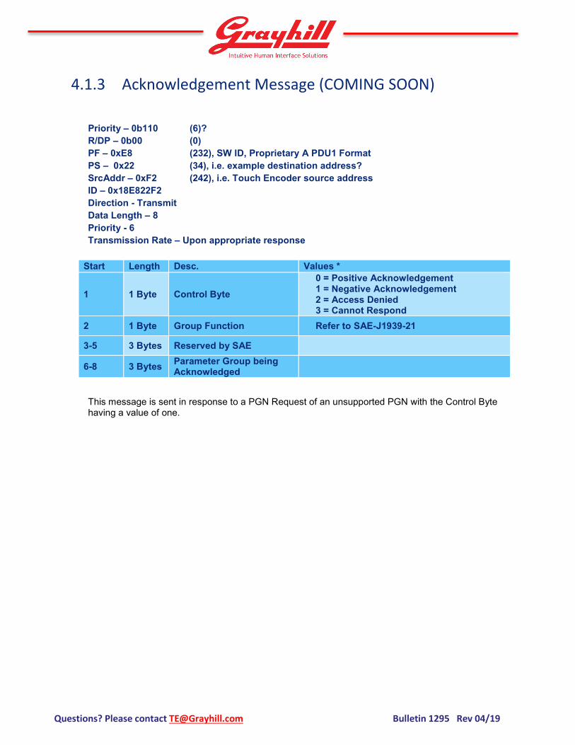
4.1.3 Acknowledgement Message (COMING SOON)
Priority – 0b110 (6)? R/DP – 0b00 (0) PF – 0xE8 (232), SW ID, Proprietary A PDU1 Format PS – 0x22 (34), i.e. example destination address? SrcAddr – 0xF2 (242), i.e. Touch Encoder source address ID – 0x18E822F2 Direction - Transmit Data Length – 8 Priority - 6 Transmission Rate – Upon appropriate response
Start Length Desc. Values *
1 1 Byte Control Byte 0 = Positive Acknowledgement 1 = Negative Acknowledgement 2 = Access Denied 3 = Cannot Respond
2 1 Byte Group Function Refer to SAE-J1939-21
3-5 3 Bytes Reserved by SAE
6-8 3 Bytes Parameter Group being Acknowledged
This message is sent in response to a PGN Request of an unsupported PGN with the Control Byte having a value of one.

Questions? Please contact [email protected] Bulletin 1295 Rev 04/19
5. Appendix 5.1 Programming Harness

Questions? Please contact [email protected] Bulletin 1295 Rev 04/19
561 Hillgrove Avenue La Grange, IL 60525
web: www.grayhill.com e-mail: [email protected]
phone: +1 (708) 354-1040 About Grayhill Grayhill, Inc. is a privately held firm which designs and manufacturers intuitive human interface solutions that make life simpler, safer, and more efficient. Standard products include optical and Hall Effect encoders, discrete and Hall Effect joysticks, rotary switches, keypads, and pushbuttons; all with finely tuned haptics. Grayhill specializes in creating ergonomic panels and product shells that integrate various interface technologies, including displays, our components, and gesture recognizing multi-touch technology. With headquarters in La Grange, Illinois, and multiple state-of-the-art facilities around the world, Grayhill’s team has the full engineering, product development and manufacturing expertise to deliver both standard and customized products quickly and cost-effectively. To learn more about Grayhill’s products and capabilities, visit www.grayhill.com.