touchscreen room pressure monitor
TRANSCRIPT

TOUCHSCREEN ROOM PRESSURE MONITOR PMT Series
MANUAL v112 FIRMWARE v2.5.X / CARD v6.1.x

TABLE OF CONTENTS
TABLE OF CONTENTS ......................................................................................................................................................................I
INTRODUCTION ...............................................................................................................................................................................2
General ..........................................................................................................................................................................................2 Product Overview .........................................................................................................................................................................2 Technical Specifications ................................................................................................................................................................3
GETTING STARTED WITH THE PMT................................................................................................................................................4
In the Box ......................................................................................................................................................................................4 Optional Accessories.....................................................................................................................................................................5
ELECTRICAL INSTALLATION ...........................................................................................................................................................6
Sample Wiring Diagram.................................................................................................................................................................6 Sensor Information Network (S.I.N.) .............................................................................................................................................7 BACnet MS/TP Network ...............................................................................................................................................................8
MECHANICAL INSTALLATION.........................................................................................................................................................9
Installation and Mounting Instructions ..........................................................................................................................................9
DISPLAY NAVIGATION ...................................................................................................................................................................12
Initial Setup .................................................................................................................................................................................12 Home Screen ..............................................................................................................................................................................15 BACnet Point Monitoring ............................................................................................................................................................17 PMT Operation ............................................................................................................................................................................18
SETTINGS .......................................................................................................................................................................................19
Room Configuration ....................................................................................................................................................................20 Alarms .........................................................................................................................................................................................20 Inputs ..........................................................................................................................................................................................22 Outputs .......................................................................................................................................................................................26 Network ......................................................................................................................................................................................28 User Preferences ........................................................................................................................................................................29 Diagnostic ...................................................................................................................................................................................30 About ...........................................................................................................................................................................................30
TROUBLESHOOTING .....................................................................................................................................................................31
Replacement Parts ......................................................................................................................................................................32 Technical Support ........................................................................................................................................................................32

TOUCHSCREEN ROOM PRESSURE MONITOR - MANUAL
| PMT – Manual | AntecControls.com 2
INTRODUCTION
General In this manual, you will find information regarding:
• Touchscreen Room Pressure Monitor (PMT) specifications • How to install the PMT • Detailed description of PMT display navigation and
configuration • Troubleshooting information
Product Overview The PMT is designed to provide ease of use pressure monitoring.
The PMT Home screen provides monitoring information in a simple format displaying information including Room Status, Pressure Mode, and Isolation Mode.
Upon swiping the screen to the left, room pressure measurement is visually available.
Some of its key features include:
• Password protected menus • Setup Wizard – Walk through setup of PMT when first
powered up • LED side bars offer 180° viewing of current room status
CAUTION This mark indicates an important point for the proper function of the PMT. Improper installation or setup may cause unit failure. Pay close attention to all caution points and tech tips throughout this manual.
For local area support, please contact your local Antec Controls Representative
For more information visit www.AntecControls.com

TOUCHSCREEN ROOM PRESSURE MONITOR - MANUAL
| PMT – Manual | AntecControls.com 3
Technical Specifications
Environmental (Operating)
50°F to 95°F (10°C to 35°C), 0% to 95% R.H. (non-condensing)
Environmental (Storage)
-22°F to 122°F (-30°C to 50°C), 0% to 95% R.H. (non-condensing)
Input Power 24 VAC +/- 10%, 50/60 Hz, 34 VA (external loads not included), Class 2
Inputs
1 Binary Input,
1 Binary/Analog Input,
1 Sensor Information Network Input
Outputs
2 Analog Outputs (0 to 10 VDC, Max: 10 mA),
1 Dry Binary Output (Max: 24 VAC/VDC, 100 mA),
1 Sin Power Output (34 VDC, Max: 300 mA)
Display Type Capacitive Touch, 4.3in. (109mm) TFT/IPS, dimmable
Resolution WVGA RGB 480px × 272px
Communication Protocol BACnet, SIN
BACnet
Device Type B-ASC
Communication Type MS/TP (RS-485)
Communication Speed 9600, 19200, 38400, 76800
Certification BTL
Control Priority Order 1. BACnet
2. Normal Operation
Room Pressure Sensors (SRPS)
Environmental (Operating) 50°F to 95°F (10°C to 35°C),
0% to 95% R.H. (non-condensing)
Environmental (Storage) -22°F to 122°F (-30°C to 50°C),
0% to 95% R.H. (non-condensing)
Input Power Powered from PMT
Range +/- 0.1 in.w.c. (+/- 25 Pa)
Accuracy 3% of reading
Pressure Tubing 24in. (588mm) long, black, fir-rated
5/32” ID × 9/32” OD × 1/16” W
Face Plate ABS plastic (white), Stainless Steel

TOUCHSCREEN ROOM PRESSURE MONITOR - MANUAL
| PMT – Manual | AntecControls.com 4
GETTING STARTED WITH THE PMT
In the Box
Touchscreen Room Pressure Monitor (PMT)
Component Quantity Description Touchscreen Room Pressure Monitor (PMT)
1
Single PMT
120-ohm resistor (not pictured)
2 120-ohm resistors to be used to terminate the SIN and BACnet MS/TP networks
Room Pressure Sensor (SRPS)
Component Quantity Description Room Pressure Sensor
1 for single room application 2 for dual room application 3 for triple room application
Single SRPS
Sensor Plate 2 for single room application 4 for dual room application 6 for triple room application
Sensor plate, available in either plastic or stainless steel
Kink Resistant Air Tubing – 24”
2 for single room application 4 for dual room application 6 for triple room application
Air pressure tubing to connect between Sensor Plate and Room Pressure Sensor
CAUTION Please ensure you have all components before proceeding. Inspect components for shipping damage. Do not install any components that appear damaged, contact your local Antec Controls Representative for replacements.
For the latest information and videos please visit www.AntecControls.com
TOUCHSCREEN ROOM PRESSURE MONITOR - MANUAL
| PMT – Manual | AntecControls.com 5
Optional Accessories
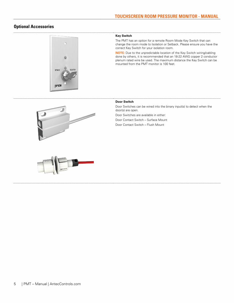
Key Switch
The PMT has an option for a remote Room Mode Key Switch that can change the room mode to Isolation or Setback. Please ensure you have the correct Key Switch for your isolation room.
NOTE: Due to the unpredictable location of the Key Switch wiring/cabling done by others, it is recommended that an 18-22 AWG copper 2 conductor plenum rated wire be used. The maximum distance the Key Switch can be mounted from the PMT monitor is 100 feet.
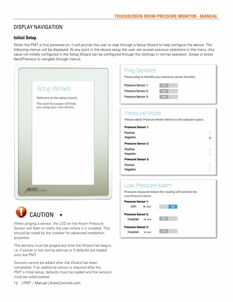
Door Switch
Door Switches can be wired into the binary input(s) to detect when the door(s) are open.
Door Switches are available in either:
Door Contact Switch – Surface Mount
Door Contact Switch – Flush Mount

TOUCHSCREEN ROOM PRESSURE MONITOR - MANUAL
| PMT – Manual | AntecControls.com 6
ELECTRICAL INSTALLATION
Sample Wiring Diagram
NOTES:
1. For typical network wiring diagrams see the Sensor Information Network (S.I.N.) and BACnet MS/TP Network sections. 2. All wire connections to the monitor screw connection terminals must be between 16-26 AWG wire. 3. All wire connections to the SRPS screw terminals must be between 12-30 AWG wire. 4. Current and voltage drop should be considered when selecting wire gauge. 5. Wiring above may not reflect those required for your project. Refer to your Antec Controls Project Submittals for project
specific wiring diagrams.
Terminal Block Usages
Description 1 The PMT connects to the room pressure sensor through the S.I.N. (Sensor Information Network)
terminal. 2 The PMT has native BACnet capabilities; connection is made through this BACnet MS/TP
terminal. 3 The Contact Closure allows the user to provide a binary signal on a variety of inputs. 4 The Configurable Input is typically used for the Room Mode Key Switch; however, it has the
same capabilities as the Binary Input. 5 The Binary Input can be used to trigger setback, isolation, alarms, or cautions. 6 The PMT’s two Analog Outputs allow the user to provide a configurable 0 to 10 VDC signal on a
variety of inputs.
2 1
3 6 5 4

TOUCHSCREEN ROOM PRESSURE MONITOR - MANUAL
| PMT – Manual | AntecControls.com 7
Sensor Information Network (S.I.N.) The Sensor Information Network (SIN) is a communication protocol between the PMT and the SIN Room Pressure Sensor (SRPS). SIN allows for digital communication between multiple SRPSs and one single PMT touchscreen.
Network Addressing SIN devices will come from the factory with predefined MAC addresses. No addressing on-site is required. Limit of three SIN devices on one Sensor Information Network.
PMT Configuration Settings When multiple SRPS are connected to a single PMT, each SRPS will self address. Please ensure that each SRPS is pinged during the Setup Wizard and the SRPS addressing (1, 2, or 3) is recorded to each room placement. Once the wizard is complete, the display order can be adjusted in the Display menu, if required (see User Preferences - Display).
Physical Connection SIN consists of a 4-wire network architecture (VBUS, VCOM, D+ and D-) using a daisy chain connection between each device on the network segment.
Wiring Requirements • Twisted pair wire (24 AWG) • Characteristic impedance: 100 – 130 ohms • Capacitance between conductors: Less than 30pF per
foot (100pF per meter) • Maximum length between each device: 50 feet (15
meters)
NOTE: Polarity must be maintained across all devices.
NOTE: Installer must use a 100 ohm resistor at both SIN end of line terminations of the “+” and “-” terminals.
CAUTION If the PMT is already set up and an additional SRPS is removed or added to the SIN communication line, please restore defaults on the PMT and re-run the Setup Wizard.

TOUCHSCREEN ROOM PRESSURE MONITOR - MANUAL
| PMT – Manual | AntecControls.com 8
BACnet MS/TP Network BACnet MS/TP is a communication protocol for communication between the PMT and the building automation network. BACnet communication allows the end user to verify rooms are operating as expected and allows them to set up trends to monitor safety, and any alarms that occur.
Each PMT will require a connection to BACnet to transmit its information to the BMS.
BACnet Points See Touchscreen Room Pressure Monitor (PMT) Product Submittal at AntecControls.com for BACnet Points List.
Physical Connection BACnet consists of a 3-wire network architecture. Daisy chain the +, -, and COM connections of all devices on the network segment as shown in Figure 5.
When using shielded cable, ground the shield at one end of the network segment only. Connect the shield of the cable entering a device to that of the cable exiting the device.
Terminate the MS/TP network segment at each end of the network segment by connecting a 120-ohm resistor between the + and – terminals. Remove the termination resistor or disable any network terminations on all devices when adding devices to an existing network segment.
Wiring Requirements • Twisted pair • Shielded (either foil or braided shields) • Characteristic impedance: 100 – 130 ohms • Capacitance between conductors: Less than 30pF per
foot (100pF per meter) • Maximum length of MS/TP Segment: 1050 feet (320
meters) • Maximum number of devices on MS/TP Segment: 32
Network Termination The MS/TP network must be terminated at each end of the network segment. Termination involves connecting a 100-130 ohm resistor between the “+” and “-“ network terminals. Some devices are terminated by default (e.g. Routers) and some have optional hardware or software termination settings.
Network Addressing When configuring the PMT, the user needs to assign the unique identifying address for the room.
On any BACnet MS/TP network:
• MAC Address can be between 0 and 127 and must be unique to the MS/TP segment.
• Device Instance can be between 0 and 4,194,303 and must be unique to the facility.
• Baud rate can be 9,600, 19,200, 38,400, or 76,800 and must match that of the Router/System Controller for the MS/TP segment.
NOTE: Installer must use a 100 ohm resistor at both SIN end of line terminations of the “+” and “-” terminals.

TOUCHSCREEN ROOM PRESSURE MONITOR - MANUAL
| PMT – Manual | AntecControls.com 9
MECHANICAL INSTALLATION
Installation and Mounting Instructions
Touchscreen Installation Instructions
Mount the Touchscreen Room Pressure Monitor (PMT) near the doorway using a standard single-gang electrical box (by others) at a height of 5 feet.
Ensure LED bars are not blocked by other devices on the wall.
Leave space below the PMT to ensure the set screw can be tightened.

TOUCHSCREEN ROOM PRESSURE MONITOR - MANUAL
| PMT – Manual | AntecControls.com 10
Pressure Sensor Installation Instructions
Once the installation locations have been selected, the Sensor Plates can be mounted using the followings steps.
Selecting a Location for Installation
There are three components that are to be installed for each space that requires pressure monitoring:
1. A Sensor Plate inside the room
2. A Sensor Plate outside the room
3. A Room Pressure Sensor
NOTE: If the PMT is monitoring multiple spaces, the following steps will need to be repeated for every space.
Begin by determining installation locations for each of these components.
1. The best installation location for the Sensor Plates is typically above a doorway or in the ceiling tile. Things to keep in mind when determining the location for the sensor plates:
a. Ensure that nothing can be placed in front of the pressure sensor, blocking its ability to measure the room pressure accurately.
b. Be wary of diffuser placement in relation to the sensor. Turbulent airflow passing over the sensor plate can cause unstable pressure readings.
2. The Room Pressure Sensor can be mounted in the plenum space either in the room, or in the reference space. Important notes:
a. The sensor must be within 24” of each of the sensor plates. If tubing length exceeds 24”, sensor must be scaled with Test and Balance present.
b. The sensor should be easily accessible for wiring and setup.
CAUTION Incorrect placement can affect the sensor’s readings.

TOUCHSCREEN ROOM PRESSURE MONITOR - MANUAL
| PMT – Manual | AntecControls.com 11
If mounting the Sensor Plate directly to the wall or ceiling tile:
1. Cut a 1 in. hole for the tubing to pass through.
2. Use the pressure plate to mark the holes for the anchors (anchors require 3/16” drill). Drill hole and install the provided anchors.
3. Push the 24” black tubing onto the pickup on the back of the Sensor Plate.
4. Run the tubing through the 1 in. hole in the wall/ceiling tile and mount the plate to the surface using screws provided.
5. Connect tubing to the Room Pressure Sensor.
a. Monitored space to high pressure port.
b. Reference space to low pressure port.
If mounting the Sensor Plate to a single gang electrical box:
1. Knockout a hole for the tubing to pass through.
2. Pushing the 24” black tubing onto the pickup on the back of the Sensor Plate.
3. Run the tubing through the electrical box or conduit.
4. Using the provided screws, mount the sensor plate to the electrical box.
5. Connect tubing to the Room Pressure Sensor.
a. Monitored space to high pressure port
b. Reference space to low pressure port.
CAUTION Make note if the tubing is reversed when installed. If the corridor is connected to the high pressure port on the sensor, the reading can be reversed during setup.
Maximum of 10 ft total length of tubing before the is significant signal degradation
Do not connect tubing from the SRPS to any other pressure measurement devices.
TOUCHSCREEN ROOM PRESSURE MONITOR - MANUAL
| PMT – Manual | AntecControls.com 12
DISPLAY NAVIGATION
Initial Setup When the PMT is first powered on, it will prompt the user to step through a Setup Wizard to help configure the device. The following menus will be displayed. At any point in the device setup the user can access previous selections in the menu. Any value not initially configured in the Setup Wizard can be configured through the Settings in normal operation. Swipe or press Next/Previous to navigate through menus.
CAUTION When pinging a sensor, the LED on the Room Pressure Sensor will flash to notify the user where it is installed. This should be noted by the installer for advanced installation purposes.
The sensors must be pinged any time the Wizard has begun, i.e. if power is lost during start-up or if defaults are loaded onto the PMT.
Sensors cannot be added after the Wizard has been completed. If an additional sensor is required after the PMT’s initial setup, defaults must be loaded and the sensors must be rediscovered.

TOUCHSCREEN ROOM PRESSURE MONITOR - MANUAL
| PMT – Manual | AntecControls.com 13

TOUCHSCREEN ROOM PRESSURE MONITOR - MANUAL
| PMT – Manual | AntecControls.com 14

TOUCHSCREEN ROOM PRESSURE MONITOR - MANUAL
| PMT – Manual | AntecControls.com 15
Home Screen The PMT Home Screen displays once the PMT Setup Wizard has been completed.
The Home Screen provides the user with a clear indication of the monitor mode, status, and pressure reading.
Single Room Monitoring
Single Room Display Components
Display Component
Description
1 Monitor Name The current name of the monitor is displayed. This is configurable through the User Preferences menu.
2 Settings Button Allows access to settings. This is password protected.
Password: 1-6-6-4. 3 Room Status Indicates whether the room is maintaining the desired setpoints in its
current mode. 4 Pressure Mode Indicates whether the room is in Negative or Positive Isolation mode.
5 Room Mode Allows the user to select between Isolation and Setback modes. When a
Room Mode Key Switch is installed, this option will be disabled on the PMT Home Screen. This ensures that control is maintained from only one location and ensures that the key switch will always match the Room Mode. This is password protected and the password is configurable through the User Preferences menu.
Default Password: 1-2-3-4.
Single Room Setback Mode
Once in Setback mode, the PMT will continue to monitor room pressure; however, all alarms will be disabled. The Home Screen will only show the room status.

TOUCHSCREEN ROOM PRESSURE MONITOR - MANUAL
| PMT – Manual | AntecControls.com 16
CAUTION Each individual room can be configured with its own alarms or cautions. For example, when one room goes into alarm, the alarm indication will be isolated to that display section of the monitor.
Multi-Room Monitoring The PMT can also be used to monitor the pressure in multiple rooms. Up to three rooms can be monitored simultaneously on one display.
The Multi-Room Monitoring display will include the Monitor Name, Settings menu, and Room Mode buttons, similar to Single Room Monitoring.
In addition, the following will be displayed for each individual room.
Multi-Room Display Components
Display Component
Description
1 Room Name The name of the room associated with each room pressure sensor. Each name is customizable through the User Preferences menu.
2 Room Status Indicates whether each individual room is maintaining its pressure setpoint in its current mode.
3 Pressure Mode Indicates whether each individual room is in Negative or Positive Isolation mode. Each room can be configured individually for either Negative or Positive Isolation.
Multi-Room Setback Mode
When the monitor is put into Setback Mode, all rooms will go into Setback. All rooms will still monitor pressure, but the alarms in every room will be inactive.

TOUCHSCREEN ROOM PRESSURE MONITOR - MANUAL
| PMT – Manual | AntecControls.com 17
BACnet Point Monitoring
Single Screen BACnet Point Monitoring:
The user can configure the PMT to show any combination of Temperature, Relative Humidity, or Air Change Rate from another device. These values can come from any device on the same BACnet MS/TP communication line as the PMT.
Once configured to display the appropriate values, there are multiple display configurations available for the Home Screen of the PMT.
All BACnet points for a single room can be displayed on a single screen.
Multiple Screen BACnet Point Monitoring:
When monitoring multiple rooms, the BACnet points for each room will be displayed on a single screen. The user can then swipe to display the different environmental values for each room.
CAUTION The user’s location in the multiple screens is indicated at the bottom of the screen above the Room Mode button.
CAUTION This display method is only available when monitoring a single room

TOUCHSCREEN ROOM PRESSURE MONITOR - MANUAL
| PMT – Manual | AntecControls.com 18
PMT Operation When fully set up the PMT can be set to monitor positive or negative pressure. Alarms for low/high pressure are fully field configurable. The PMT has four Room Status Conditions:
Mode Status LCD Display LED Bars Alarm
Negative/Positive Pressure Monitoring (Room Occupied)
Normal – Pressure reading within low/high setpoints
Green Off
Negative/Positive Pressure Monitoring (Room Occupied)
Caution – Pressure reading outside low/high caution setpoints
Yellow Off
Negative/Positive Pressure Monitoring (Room Occupied)
Alarm – Pressure reading outside low/high alarm setpoints
Red On
Neutral (Room Setback) Setback – Pressure measured but no alarms
Blue Off
Silence Screen:
When occupied, the PMT will monitor and display the primary room pressure.
If the pressure reading is within the low and high alarm setpoints, the LED bars will be green and the alarm will be off.
If the pressure reading is outside of either the low or high alarm setpoints, the LED bars will turn red and the local alarm will turn on.
Alarm Silence
Used to temporarily mute the local alarm for a selected number of minutes. This silence time defaults to a 5 minute delay.
Time delay adjustable in the Alarms menu on page 20.
If the Room Pressure Sensor (SRPS) is unplugged from the PMT while in occupied mode, the LED bars will turn red and the local alarm will turn on.
TOUCHSCREEN ROOM PRESSURE MONITOR - MANUAL
| PMT – Manual | AntecControls.com 19
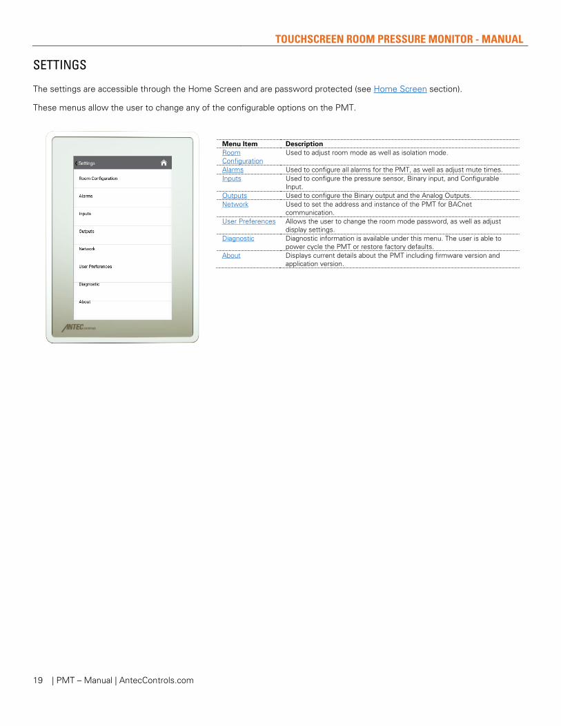
SETTINGS
The settings are accessible through the Home Screen and are password protected (see Home Screen section).
These menus allow the user to change any of the configurable options on the PMT.
Menu Item Description Room Configuration
Used to adjust room mode as well as isolation mode.
Alarms Used to configure all alarms for the PMT, as well as adjust mute times. Inputs Used to configure the pressure sensor, Binary input, and Configurable
Input. Outputs Used to configure the Binary output and the Analog Outputs. Network Used to set the address and instance of the PMT for BACnet
communication. User Preferences Allows the user to change the room mode password, as well as adjust
display settings. Diagnostic Diagnostic information is available under this menu. The user is able to
power cycle the PMT or restore factory defaults. About Displays current details about the PMT including firmware version and
application version.
TOUCHSCREEN ROOM PRESSURE MONITOR - MANUAL
| PMT – Manual | AntecControls.com 20
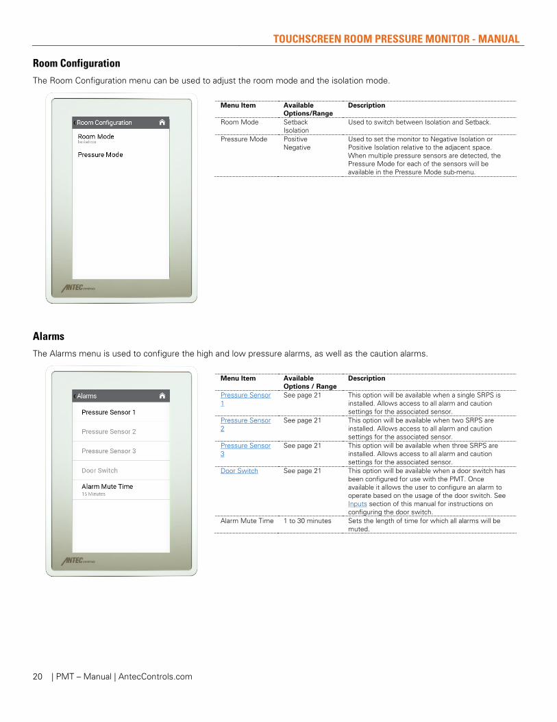
Room Configuration The Room Configuration menu can be used to adjust the room mode and the isolation mode.
Menu Item Available Options/Range
Description
Room Mode Setback Isolation
Used to switch between Isolation and Setback.
Pressure Mode Positive Negative
Used to set the monitor to Negative Isolation or Positive Isolation relative to the adjacent space. When multiple pressure sensors are detected, the Pressure Mode for each of the sensors will be available in the Pressure Mode sub-menu.
Alarms The Alarms menu is used to configure the high and low pressure alarms, as well as the caution alarms.
Menu Item Available Options / Range
Description
Pressure Sensor 1
See page 21 This option will be available when a single SRPS is installed. Allows access to all alarm and caution settings for the associated sensor.
Pressure Sensor 2
See page 21 This option will be available when two SRPS are installed. Allows access to all alarm and caution settings for the associated sensor.
Pressure Sensor 3
See page 21 This option will be available when three SRPS are installed. Allows access to all alarm and caution settings for the associated sensor.
Door Switch See page 21 This option will be available when a door switch has been configured for use with the PMT. Once available it allows the user to configure an alarm to operate based on the usage of the door switch. See Inputs section of this manual for instructions on configuring the door switch.
Alarm Mute Time 1 to 30 minutes Sets the length of time for which all alarms will be muted.

TOUCHSCREEN ROOM PRESSURE MONITOR - MANUAL
| PMT – Manual | AntecControls.com 21
Alarms – Pressure Sensor Pressure Sensor 1, Pressure Sensor 2, and Pressure Sensor 3 have the following options.
Menu Item Available Options/Range
Description
Low Pressure Alarm
Setpoint On/Off Delay On/Off
Set the activation point for the Low Pressure Alarm, as well as the time delay of this alarm. The Low Pressure Alarm on the PMT is used to indicate if the room is too close to neutral, i.e. not pressurized enough.
High Pressure Alarm
Setpoint On/Off Delay On/Off
Set the activation point for the High Pressure Alarm, as well as the time delay of this alarm. The High Pressure Alarm on the PMT is used to indicate if the room is too negative or positive (depending on Pressure Mode), i.e. over pressurized.
Low Pressure Caution
Setpoint On/Off Delay On/Off
Set the activation point for the Low Pressure Caution alarm, as well as the time delay of this caution alarm.
High Pressure Caution
Setpoint On/Off Delay On/Off
Set the activation point for the High Pressure Caution alarm, as well as the time delay of this caution alarm.
Alarms – Door Switch
Menu Item Available Options/Range
Description
Door Alarm Disabled Enabled
Allows the user to configure the Binary Input.
Delay 0 to 600 seconds Enables and sets the door alarm delay. Caution During Alarm Delay
No Yes
Enables caution mode when during the user-set delay period.
TOUCHSCREEN ROOM PRESSURE MONITOR - MANUAL
| PMT – Manual | AntecControls.com 22
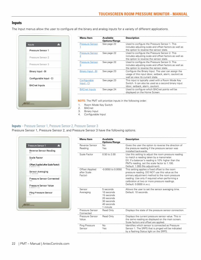
Inputs The Input menus allow the user to configure all the binary and analog inputs for a variety of different applications.
Menu Item Available Options/Range
Description
Pressure Sensor 1
See page 22 Used to configure the Pressure Sensor 1. This includes adjusting scale and offset factors as well as the option to reverse the sensor state.
Pressure Sensor 2
See page 22 Used to configure the Pressure Sensor 2. This includes adjusting scale and offset factors as well as the option to reverse the sensor state.
Pressure Sensor 3
See page 22 Used to configure the Pressure Sensor 3. This includes adjusting scale and offset factors as well as the option to reverse the sensor state.
Binary Input - BI See page 23 Configure the Binary Input. The user can assign the usage of this input (door, setback, alarm, caution) as well as view its current state.
Configurable Input - CI
See page 23 This input is typically used with a Room Mode Key Switch. It can also be used as a second binary input (door, setback, alarm, caution).
BACnet Inputs See page 24 Used to configure which BACnet points will be displayed on the Home Screen.
NOTE: The PMT will prioritize inputs in the following order:
1. Room Mode Key Switch 2. BACnet 3. Binary Input 4. Configurable Input
Inputs – Pressure Sensor 1, Pressure Sensor 2, Pressure Sensor 3 Pressure Sensor 1, Pressure Sensor 2, and Pressure Sensor 3 have the following options.
Menu Item Available Options/Range
Description
Reverse Sensor Reading
No Yes
Gives the user the option to reverse the direction of the pressure reading if the pressure sensor was installed backwards.
Scale Factor 0.50 to 2.00 Use this setting to adjust the room pressure reading to match a reading taken by a manometer. EX: If a balancer’s reading is 10% higher than the PMTs reading, set the scale factor to 1.100. Default: 1.000 (No adjustment).
Offset (Applied after Scale Factor)
-0.0050 to 0.0050 This setting applies a fixed offset to the room pressure reading. DO NOT use this value as the primary adjustment method to the room pressure reading. Use only if required when performing a calibration at two or more pressure readings. Default: 0.0000 in.w.c.
Sensor Averaging
5 seconds 10 seconds 15 seconds 20 seconds 30 seconds 40 seconds 1 minute
Allows the user to set the sensor averaging time. Default: 10 seconds.
Pressure Sensor Connected
Read Only Displays the state of the pressure sensor connection.
Pressure Sensor Value
Read Only Displays the current pressure sensor value. This is the same reading as displayed on the main screen. Scale factors and offset are applied.
Ping Pressure Sensor
No Yes
Identifies which sensor is connected as Pressure Sensor 1. The SRPS that is pinged will be indicated by a flashing Status light on the SRPS.

TOUCHSCREEN ROOM PRESSURE MONITOR - MANUAL
| PMT – Manual | AntecControls.com 23
Inputs – Binary Input - BI
Menu Item Available Options/Range
Description
Usage
None The Binary Input is not tied to any functionality within the PMT. Its current state is visible to the BACnet front end.
Door This allows the user to configure a door switch. Once selected for the Binary Input, the user must configure the “Door Switch” setting under the Alarms menu.
Setback When the Binary Input is open/closed the monitor will change to Setback mode.
Alarm When the Binary Input is open/closed the monitor will go into Alarm mode.
Caution When the Binary Input is open/closed the monitor will go into Caution mode.
Reverse State No Yes
Allows the user to reverse the action of the Binary Input.
Current State Read Only Displays the current state of the Binary Input. Alert Message User defined Allows the user to configure the alert message on
the home screen. Only available when BI Usage is set to Alarm or Caution.
Inputs – Configurable Input - CI
Menu Item Available Options/Range
Description
Usage
None The Configurable Input is not tied to any functionality within the PMT. Its current state is visible to the BACnet front end.
Door This allows the user to configure a door switch. Once selected for the Configurable Input, the user must configure the “Door Switch” setting under the Alarms menu.
Setback When the Configurable Input is open/closed the monitor will change to Setback mode.
Alarm When the Configurable Input is open/closed the monitor will go into Alarm mode.
Caution When the Configurable Input is open/closed the monitor will go into Caution mode.
Key Switch - Room Mode
When the Room Mode Key Switch is enabled, the Configurable Input will have full control of the room mode. It allows the user to change between Setback and Isolation mode.
Reverse State No Yes
Allows the user to reverse the action of the Configurable Input.
Current State Read Only Displays the current state of the Configurable Input. Alert Message User defined Allows the user to configure the alert message on
the home screen. Only available when CI Usage is set to Alarm or Caution.

TOUCHSCREEN ROOM PRESSURE MONITOR - MANUAL
| PMT – Manual | AntecControls.com 24
Inputs – BACnet Inputs
Menu Item Available Options/Range
Description
Polling Status On Off
Allows the user to enable polling to monitor BACnet points for Room Temperature, Relative Humidity, and Air Change Rate.
Room Temperature
See next page Allows the user to configure the BACnet settings to display Room Temperature from a BACnet MS/TP device. After pressing on Room Temperature, a list of available rooms to configure will be shown.
Relative Humidity
See next page Allows the user to configure the BACnet settings to display Relative Humidity from a BACnet MS/TP device. After pressing on Relative Humidity, a list of available rooms to configure will be shown.
Air Change Rate See next page Allows the user to configure the BACnet settings to display Air Change Rate from a BACnet MS/TP device. After pressing on Air Change Rate, a list of available rooms to configure will be shown.
Read Request Timeout
0 to 10 seconds Allows the user to configure the time until a new BACnet request is sent after a BACnet Timeout error occurs.
Alternatively, Read Request Timeout can be changed on the BAS by changing the APDU Timeout value. The APDU Timeout value is in milliseconds.
Delay Between Read Requests
0 to 60 seconds Allows the user to configure the time between BACnet read requests.
Estimated Total Time BACnet Requests
Read Only Displays the approximate total time of a BACnet request.
Total BACnet Error
Read Only Displays the total number of errors BACnet has received. The maximum total BACnet error value that can be displayed is 100.
Reset Total BACnet Errors
Yes No
Resets the value of total BACnet errors.
NOTE: BACnet monitoring for Room Temperature, Room Humidity, and Air Change Rate is limited to a maximum number of rooms as there are SRPS sensors connected to the PMT, i.e. the user cannot set the PMT to display Room Temperature from two rooms if only one is connected to the PMT.
TOUCHSCREEN ROOM PRESSURE MONITOR - MANUAL
| PMT – Manual | AntecControls.com 25
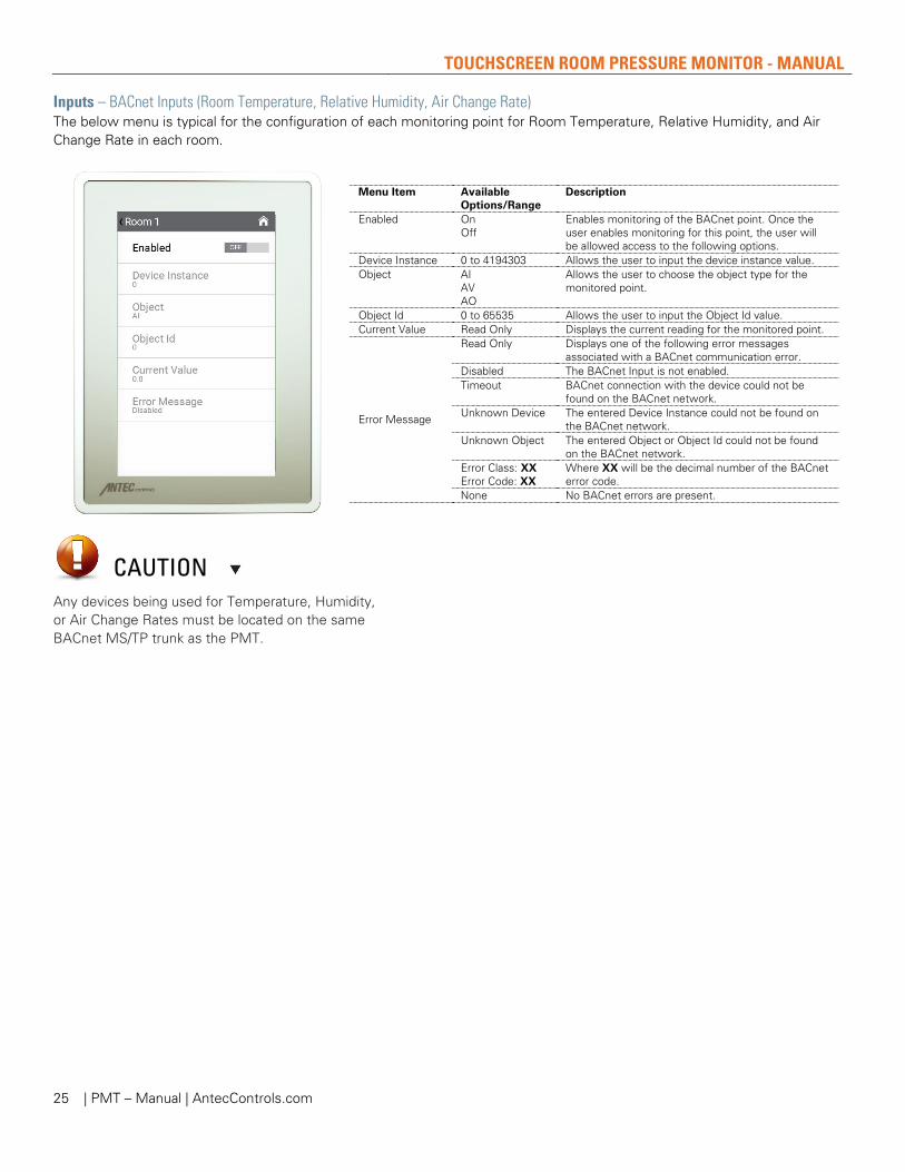
CAUTION Any devices being used for Temperature, Humidity, or Air Change Rates must be located on the same BACnet MS/TP trunk as the PMT.
Inputs – BACnet Inputs (Room Temperature, Relative Humidity, Air Change Rate) The below menu is typical for the configuration of each monitoring point for Room Temperature, Relative Humidity, and Air Change Rate in each room.
Menu Item Available Options/Range
Description
Enabled On Off
Enables monitoring of the BACnet point. Once the user enables monitoring for this point, the user will be allowed access to the following options.
Device Instance 0 to 4194303 Allows the user to input the device instance value. Object AI
AV AO
Allows the user to choose the object type for the monitored point.
Object Id 0 to 65535 Allows the user to input the Object Id value. Current Value Read Only Displays the current reading for the monitored point.
Error Message
Read Only Displays one of the following error messages associated with a BACnet communication error.
Disabled The BACnet Input is not enabled. Timeout BACnet connection with the device could not be
found on the BACnet network. Unknown Device The entered Device Instance could not be found on
the BACnet network. Unknown Object The entered Object or Object Id could not be found
on the BACnet network. Error Class: XX Error Code: XX
Where XX will be the decimal number of the BACnet error code.
None No BACnet errors are present.

TOUCHSCREEN ROOM PRESSURE MONITOR - MANUAL
| PMT – Manual | AntecControls.com 26
Outputs The Output menus allow the user to configure all the Binary and Analog Outputs for a variety of different applications.
Menu Item Description Binary Output - BO
Used to set the usage of the Binary Output between multiple types of usages.
Analog Outputs Used to set the usage of the Analog Outputs between multiple types of usages.
Outputs – Binary Output - BO
Menu Item Available Options / Range
Description
Usage
None The Binary Output is unused. Alarm The BO will be active when the monitor goes into
Alarm while in Isolation Mode. Caution The BO will be active when the monitor goes into
Caution while in Isolation Mode. Normal The BO will be active when the monitor is in normal
operation while in Isolation Mode. Setback The BO will be active when the monitor is in Setback
mode. Door Status The BO will be active when the door is open/closed
(depending on the door switch state). Binary Input – BI The BO will follow the status of the Binary Input. Configurable Input – CI
The BO will follow the status of the Configurable Input.
Low Pressure The BO will be active when the room pressure is below the set Low Pressure Limit.
High Pressure The BO will be active when the room pressure is above the set High Pressure Limit.
Reverse State No Yes
Allows the user to reverse the action of the Binary Output.
Current State Read Only Displays the currents state of the Binary Output.

TOUCHSCREEN ROOM PRESSURE MONITOR - MANUAL
| PMT – Manual | AntecControls.com 27
Outputs – Analog Outputs
The PMT has two available Analog Outputs. AO1 and AO2 have the following options.
Menu Item Available Options / Range
Description
Usage
None The Analog Output is unused. Pressure -0.1 to 0.1 in.w.c.
The AO will be scaled proportionally from a -0.1 to +0.1 in.w.c. over 0 VDC to 10 VDC. • 0 VDC will correspond to -0.1 in.w.c. • 10 VDC will correspond to +0.1 in.w.c. This value can be programmed for Pressure Sensor 1, 2, or 3.
Pressure 0 to -0.1 in.w.c.
The AO will be scaled proportionally from 0 to +0.1 in.w.c. or 0 to -0.1 in.w.c. over 0 VDC to 10 VDC. • 0 VDC will correspond to 0 in.w.c. • 10 VDC will correspond to either +0.1 in.w.c.
or -0.1 in.w.c. This value can be programmed for Pressure Sensor 1, 2, or 3.
Pressure – Alarm The AO will output the active value (voltage) when the room is in Pressure – Alarm mode.
Pressure – Caution
The AO will output the active value (voltage) when the room is in Pressure – Caution mode.
Pressure – Normal
The AO will output the active value (voltage) when the room is in Pressure – Normal mode.
Setback The AO will output the active value (voltage) when the room is in Setback mode.
Door Status The AO will output the active value (voltage) based on the door switch status.
Binary Input – BI The AO will output the active value (voltage) based on the current status of the Binary Input.
Configurable Input – CI
The AO will activate based on the Configurable Input status.
Low Pressure The AO will output the active value (voltage) when room pressure is measured below the set Low Pressure Alarm threshold when the room is in Isolation mode.
High Pressure The AO will output the active value (voltage) when room pressure is measured above the set High Pressure Alarm threshold when the room is in Isolation mode.
Inactive Value 0.00 to 10.00 VDC
Sets the output voltage when the Analog Output is inactive. This value is not configurable when “Pressure -0.1 to 0.1 in.w.c.” and “Pressure 0 to -0.1 in.w.c.” are selected.
Active Value 0.00 to 10.00 VDC
Sets the output voltage when the Analog Output is active. NOTE: This value is not configurable when Usage is set to “Pressure -0.1 to 0.1 in.w.c.” or “Pressure 0 to -0.1 in.w.c.”
Current Voltage Read Only Displays the current output voltage of the analog output.

TOUCHSCREEN ROOM PRESSURE MONITOR - MANUAL
| PMT – Manual | AntecControls.com 28
Network The Network menu is used to access all options for the BACnet communication. The PMT has native BACnet available as standard.
Menu Item Available Options / Range
Description
Connection Type Disabled BACnet
Allows the user to enable/disable BACnet communication. If BACnet is not configured in the Setup Wizard, this will default to disabled.
MAC Address 1 to 127 Allows the user to set the BACnet MS/TP address.
NOTE: Ensure that no duplicate MAC addresses exist on any network segment.
Device Instance 1 to 4,189,999 This is the BACnet address and must be unique on your building site.
Baud rate 9,600 19,200 38,400 76,800
This sets the BACnet MS/TP baud rate. All devices on a BACnet segment must run at the same baud rate.
Write Settings Over BACnet
Disabled Standard Open
This sets the write privilege of the device. See the BACnet points list in the Touchscreen Room Pressure Monitor (PMT) Product Submittal at AntecControls.com for the write privileges for each of these selections.
TOUCHSCREEN ROOM PRESSURE MONITOR - MANUAL
| PMT – Manual | AntecControls.com 29
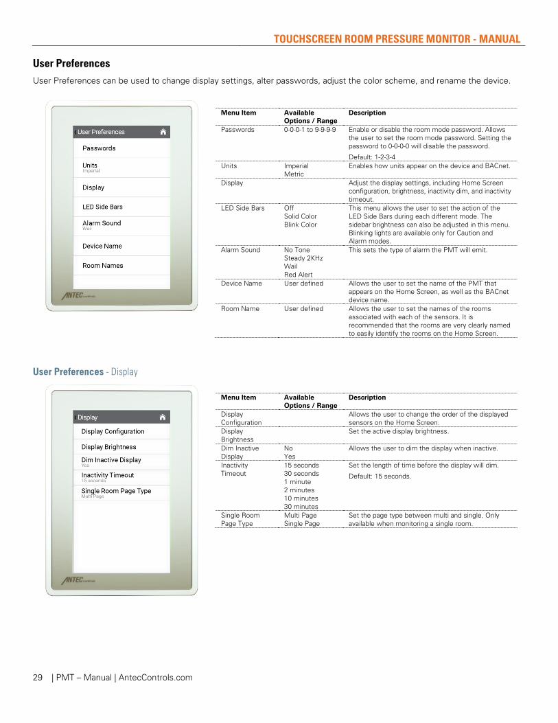
User Preferences User Preferences can be used to change display settings, alter passwords, adjust the color scheme, and rename the device.
Menu Item Available Options / Range
Description
Passwords 0-0-0-1 to 9-9-9-9 Enable or disable the room mode password. Allows the user to set the room mode password. Setting the password to 0-0-0-0 will disable the password.
Default: 1-2-3-4 Units Imperial
Metric Enables how units appear on the device and BACnet.
Display Adjust the display settings, including Home Screen configuration, brightness, inactivity dim, and inactivity timeout.
LED Side Bars Off Solid Color Blink Color
This menu allows the user to set the action of the LED Side Bars during each different mode. The sidebar brightness can also be adjusted in this menu. Blinking lights are available only for Caution and Alarm modes.
Alarm Sound No Tone Steady 2KHz Wail Red Alert
This sets the type of alarm the PMT will emit.
Device Name User defined Allows the user to set the name of the PMT that appears on the Home Screen, as well as the BACnet device name.
Room Name User defined Allows the user to set the names of the rooms associated with each of the sensors. It is recommended that the rooms are very clearly named to easily identify the rooms on the Home Screen.
User Preferences - Display
Menu Item Available Options / Range
Description
Display Configuration
Allows the user to change the order of the displayed sensors on the Home Screen.
Display Brightness
Set the active display brightness.
Dim Inactive Display
No Yes
Allows the user to dim the display when inactive.
Inactivity Timeout
15 seconds 30 seconds 1 minute 2 minutes 10 minutes 30 minutes
Set the length of time before the display will dim.
Default: 15 seconds.
Single Room Page Type
Multi Page Single Page
Set the page type between multi and single. Only available when monitoring a single room.

TOUCHSCREEN ROOM PRESSURE MONITOR - MANUAL
| PMT – Manual | AntecControls.com 30
Diagnostic The Diagnostic menu is used to display critical information for the PMT including device up time, the connection state of the pressure sensor as well as the current pressure reading. This menu can also be used to power cycle the PMT and restore factory defaults.
Menu Item Available Options / Range
Description
System Up Time Read Only Displays the elapsed time since last power cycle of the PMT.
Pressure Sensor Connection Status
Read Only Displays the connection state of the pressure sensor.
Pressure Sensor Readings
Read Only Displays the current sensor readings from each of the connected sensors.
Restore Factory Defaults
No Yes
This resets the PMT to factory defaults, restarts the device, and then prompts the user to navigate the Setup Wizard.
Reset Device No Yes
This option will power cycle the PMT.
About The About menu displays current information pertaining to the device operating system and version numbers.
Menu Item Available Options / Range
Description
Model Read Only Displays the model, PMT. Application Version
Read Only Displays the current operating system application version.
Firmware Version
Read Only Displays the current firmware version.
Operating System Version
Read Only Displays the current operating system version.
Kernel Version Read Only Displays the current kernel version. Sensor Information
Read Only Displays the Hardware and Software information for each of the connected pressure sensors.

TOUCHSCREEN ROOM PRESSURE MONITOR - MANUAL
| PMT – Manual | AntecControls.com 31
TROUBLESHOOTING
The following information is provided in the event the PMT does not appear to be functioning normally after installation.
Problem Solution
BACnet Communication Errors
1. BACnet MS/TP is based on a RS-485 network. It must be wired in a daisy chain configuration. A daisy chain means that there is only one main cable, and every network device is connected directly along its path.
Do not use Star, Bus, “T” or any other type of network configuration. Any of these other network configurations will result in an unreliable network and will make troubleshooting difficult.
Correct polarity is imperative on MS/TP wiring. Always ensure that the positive terminal on a device has the same color wire connected to it throughout the network and same for the negative terminal, e.g. two wire conductor with black and white wire – black to the positive terminal and white to the negative terminal. Keep this consistent throughout the network.
2. The network should be terminated twice: once at the beginning and again at the end of each run. This is strongly recommended.
The network speed or baud rate must be the same throughout the network.
NOTE: The default speed for Antec Controls BACnet MS/TP controls is 76,800. BACnet MS/TP currently supports 4 standard speeds which are: 9,600, 19,200, 38,400, 76,800.
3. Binary address must be unique for each device on the network. No two devices can have the same address. This includes if you are incorporating an Antec Controls product onto an existing network. Determine the existing addressing scheme for the existing network. The address is set using the Network Service menu.
4. Grounding and 24 VAC polarity: proper grounding is absolutely essential when wiring the MS/TP BACnet network. Proper grounding will prevent many potential problems that can occur in a network of devices. Common symptoms of a poorly grounded network can include inconsistent BACnet MS/TP communications and damage from voltage spikes. The most practical method of grounding is to ground every 24 VAC transformer common/neutral used to power the controls.
Connect the “common/neutral” wire of the secondary side of the transformer to earth ground – such as the ground screw in the electrical box.
5. Reset the Total BACnet Errors value in the BACnet Inputs menu. If the Total BACnet Errors value changes to zero and continues to increase, an error is present. Check the Error Message for each configured BACnet Input.
Timeout Ensure the device that the PMT is polling from has 24 VAC power. Check the BACnet wiring that connects the PMT to the device the PMT is polling from. Ensure the wires are correct and seated properly.
Unknown Device Ensure the device that the PMT is polling from has 24 VAC power. Check the Device Instance of the device the PMT is polling from. Ensure the Device Instance input on the PMT matches. Check the baud rate of the device the PMT is polling from. Ensure the baud rate on the PMT matches. Check the BACnet wiring that connects the PMT to the device the PMT is polling from. Ensure the wires are correct and seated properly.
Unknown Object Check the Object Id and Object Type of the object the PMT is polling from. Ensure the Object Id and Object Type inputs on the PMT matches.
Error Class: xx Error Code: xx
The BACnet error class and code can be searched on the Internet, which will indicate the corresponding error message. See the Technical Support section of this manual if additional service is needed.
NOTE: Reversing 24 VAC hot and common will cause the BACnet MS/TP network to stop communicating. Ensure hot and common are not reversed on any controllers.
WARNING: Controllers will still power up and run even if hot and common are reversed. However, output signals to other devices such as heaters, relays, etc. will not work as intended.

TOUCHSCREEN ROOM PRESSURE MONITOR - MANUAL
| PMT – Manual | AntecControls.com 32
Replacement Parts Replacement parts are available. Please contact your local Antec Controls Representative.
Technical Support If technical support is required, please contact us:
By Email @ [email protected]
By Phone @ 866-884-3524
Hours of Operation: Monday – Friday, 8am to 4:30pm CST
NOTE: If you will need support after hours, please contact us 48 hours in advance.
PMT is Non-Responsive Check the power connection to the PMT. Ensure the monitor has 24 VAC power with a voltmeter. Cycle power to the monitor.
Binary Output Not Functioning Ensure the PMT has 24 VAC power. Ensure the binary output has been configured to the appropriate usage.
Analog Outputs Not Functioning Ensure the PMT has 24 VAC power. Ensure the analog output has been configured to the appropriate usage. Using a voltmeter, confirm that there is a voltage output between 0 to 10 VDC. Ensure the output terminal or wire is not shorted to ground or power connection.
PMT Alarms – Missing Pressure Sensor Ensure Pressure Sensor is connected. Check the Pressure Sensor cable for damage.
Ensure the Pressure Sensor is powered.
Unable to Maintain Room Pressure Ensure low and high-pressure alarms and cautions are set to the scheduled values.
Ensure room is tightly sealed. This includes checking door jams and the gap underneath the door.
PMT Screen Not Clearly Visible (dim) Adjust the brightness settings under User Preferences.
PMT Will Not Allow Room Mode to be Changed Check the state of the configurable input and the binary input. If one of these inputs is set to control the setback mode, the PMT will not allow a user to switch room mode with this input.
Pressure Reading Frozen or Less Responsive Check pressure line to sensor and ensure it is not kinked and is properly seated on nipple. Verify averaging time set in Input menu.
Pressure Reading Inaccurate or Unstable
Check draft from nearby diffusers. Ensure there is no air stream in front of sensor. Ensure airflow is not blowing directly over sensor.
Check the pressure tubing for any kinks or blockages. To clear any blockages in the tubing, disconnect the pressure tubing from the SRPS and blow on the tubing.
Check the pressure sensor for any blockages. To clear any blockages in the pressure sensor itself, blow gently on the tubing while it is connected to the SRPS.
Check the tubing length. If the tubing is >10 ft of total length there may be issues with signal degradation.
Ensure that the tubing for the SRPS isn’t connected to any other pressure measurement devices.
PMT Screen Does Not Power Up Re-seat SD card on the back of the PMT.
Pressure Sensor is not deteced or missing
Verify wiring matches the typical SIN wiring.
LED Code for the SRPS:
Steady ON: No request from the PMT. The sensor is not communicating.
Flashing green: Currently responding to a PING request from the PMT.
Steady OFF: Transmitting data to the PMT. If the PMT does not request data for 5 seconds, the light turns back on. When the light is off (and the sensor is powered up) you know that it has been recognized by the PMT and is sending data.

Product Improvement is a continuing endeavour at Antec Controls by Price. Therefore, specifications are subject to change without notice. Consult your Sales Representative for current specifications or more detailed information. Not all products may be available in all geographic areas. All goods described in this document are warranted as described in the Limited Warranty. The complete product catalog can be viewed online at AntecControls.com ® Antec Controls by Price is a registered trademark of Price Industries Limited. © 2021. Printed in Canada. v112