touchstone tr3300-ac 802.11ac wireless router - … downloading new software, or checking your...
TRANSCRIPT
Touchstone®
TR3300-AC 802.11ac WirelessRouterUser Guide
Release 33 STANDARD 1.5 February 2015

TR3300-AC 802.11ac Wireless Router User GuideRelease 33 STANDARD 1.5
ARRIS Copyrights and Trademarks
©ARRIS Enterprises, Inc. 2015 All rights reserved. No part of this publication may bereproduced in any form or by any means or used to make any derivative work (such astranslation, transformation, or adaptation) without written permission from ARRISEnterprises, Inc. (“ARRIS”). ARRIS reserves the right to revise this publication and tomake changes in content from time to time without obligation on the part of ARRIS toprovide notification of such revision or change.
ARRIS and the ARRIS logo are all trademarks of ARRIS Enterprises, Inc. Othertrademarks and trade names may be used in this document to refer to either the entitiesclaiming the marks and the names of their products. ARRIS disclaims proprietaryinterest in the marks and names of others.
ARRIS provides this guide without warranty of any kind, implied or expressed, including,but not limited to, the implied warranties of merchantability and fitness for a particularpurpose. ARRIS may make improvements or changes in the product(s) described in thismanual at any time.
The capabilities, system requirements and/or compatibility with third-party productsdescribed herein are subject to change without notice.
Patent Notice
Protected under one or more of the following U.S. patents: http://www.arris.com/legalOther patents pending.
Release 33 STANDARD 1.5 February 2015 TR3300-AC 802.11ac Wireless Router User Guide 3
Table of Contents
Chapter 1. Overview.............................................................................. 6
Introduction.................................................................................................6
Chapter 2. Safety Requirements ............................................................... 7
FCC Part 15 .................................................................................................7
RF Exposure ..........................................................................................8
Industry Canada Compliance.............................................................................8
For Mexico...................................................................................................9
Chapter 3. Product Overview..................................................................10
About The Wireless Router ............................................................................. 10
What's in the Box?........................................................................................ 10
Items You Need........................................................................................... 10
System Requirements ................................................................................... 11
Recommended Hardware ........................................................................ 11
Windows ............................................................................................ 11
MacOS ............................................................................................... 11
Linux/other Unix .................................................................................. 11
About this Manual........................................................................................ 11
What About Security? ................................................................................... 12
Chapter 4. Installing the Wireless Router ...................................................13
Front Panel................................................................................................ 13
Indicator Lights for the TR3300-AC ................................................................... 14
Rear Panel................................................................................................. 15
Selecting an Installation Location..................................................................... 15
Desktop Mounting Instructions.................................................................. 16
Factors Affecting Wireless Range .............................................................. 16
Ethernet or Wireless?.................................................................................... 17
Connecting the Wireless Router ....................................................................... 18
Configuring the Wireless Connection................................................................. 18
Chapter 5. Basic Configuration ................................................................19
Accessing the Configuration Interface ............................................................... 19
Configuring the Wireless Network .................................................................... 20
Enabling or Disabling the Wireless Network.................................................. 20
Changing the Login Password ................................................................... 20
Changing the Default Wireless Network Name (SSID) ...................................... 21
Configuring Wi-Fi Protected Setup (WPS) .................................................... 21
Setting Up the WAN Connection................................................................ 22

Release 33 STANDARD 1.5 February 2015 TR3300-AC 802.11ac Wireless Router User Guide 4
Chapter 6. Advanced Configuration Options................................................23
LAN Setup – Configuring DHCP......................................................................... 23
LAN Setup – Adding and Deleting DHCP Clients.............................................. 24
LAN Setup – Selecting the NAT Mode ................................................................. 24
Wireless Setup – Setting the Wireless Mode......................................................... 24
Firewall – General Firewall Configuration Settings ................................................ 25
Firewall – Configuring a Virtual Server (Port Forwarding) ........................................ 25
Firewall – Configuring DMZ for Gaming or Conferencing Applications.......................... 26
Utilities – Viewing Network System Information.................................................... 27
Utilities – Restarting the Wireless Router ........................................................... 27
Utilities – Reverting to Factory Default Settings ................................................... 28
Utilities – Viewing the System Logs ................................................................... 28
Utilities – DDNS ........................................................................................... 28
Chapter 7. Wireless Router Configuration Screen Descriptions.........................29
Basic Setup................................................................................................ 29
Basic Wireless Settings........................................................................... 29
WPS Settings ....................................................................................... 30
WAN Setup ................................................................................................ 31
Dynamic ............................................................................................ 31
Static ................................................................................................ 32
DNS32
Dynamic (IPV6) .................................................................................... 33
Static (IPV6)........................................................................................ 34
LAN Setup ................................................................................................. 35
LAN Settings ....................................................................................... 35
LAN Settings (IPV6) ............................................................................... 37
Client List .......................................................................................... 38
Wireless.................................................................................................... 39
Basic Setup......................................................................................... 39
Guest Access ....................................................................................... 41
Advanced ........................................................................................... 42
StreamBoost .............................................................................................. 43
StreamBoost Settings............................................................................. 43
Priorities............................................................................................ 44
STAT: Downloads.................................................................................. 45
STAT: Up Time..................................................................................... 46
Firewall .................................................................................................... 46
Firewall Settings .................................................................................. 46
Virtual Servers..................................................................................... 47
DMZ.................................................................................................. 48
WAN Ping Blocking ................................................................................ 49

Release 33 STANDARD 1.5 February 2015 TR3300-AC 802.11ac Wireless Router User Guide 5
Remote Management ............................................................................. 49
ALG50
Utilities .................................................................................................... 51
System Information............................................................................... 51
Restart Router ..................................................................................... 52
Factory Default.................................................................................... 53
Firmware Upgrade ................................................................................ 53
System Settings.................................................................................... 54
System Log ......................................................................................... 55
DDNS................................................................................................. 55
Chapter 8. Troubleshooting ....................................................................57
The Wireless Router is plugged in, but the Power light is Off ................................... 57
I'm not getting on the Internet (all connections) .................................................. 57
I'm not getting on the Internet (Ethernet) .......................................................... 57
I'm not getting on the Internet (Wireless) ........................................................... 57
My wireless Internet connection stops working sometimes ...................................... 58
I can get on the Internet, but everything is slow .................................................. 58
Chapter 9. ARRIS Contacts......................................................................59
Before You Call ARRIS Support......................................................................... 59
By Telephone ............................................................................................. 59
By Email ................................................................................................... 62
Ask ARRIS Customer Portal ............................................................................. 63
Global Knowledge Services and Training ............................................................ 63

Release 33 STANDARD 1.5 February 2015 TR3300-AC 802.11ac Wireless Router User Guide 6
Chapter 1
Overview
Introduction
Get ready to experience the Internet’s express lane! Whether you’re checking out streamingmedia, downloading new software, or checking your email, the Touchstone TR3300-AC802.11ac Wireless Router brings it all to you faster and more reliably.
The Touchstone TR3300-AC 802.11ac Wireless Router provides four Ethernet connectionsfor use as the hub of your home/office Local Area Network (LAN). The TR3300-AC alsoprovides 802.11a/b/g/n/ac wireless connectivity for enhanced mobility and versatility.
Installation is simple and your service provider will provide assistance to you for anyspecial requirements.

Release 33 STANDARD 1.5 February 2015 TR3300-AC 802.11ac Wireless Router User Guide 7
Chapter 2
Safety Requirements
The ARRIS TR3300-AC Wireless Router complies with the applicable requirements forperformance, construction, labeling, and information when used as outlined below:
Do not use product near water (i.e. wet basement, bathtub, sink or near a swimmingpool, etc.), to avoid risk of electrocution.
The product shall be cleaned using only a damp, lint-free, cloth. No solvents orcleaning agents shall be used.
Do not use spray cleaners or aerosols on the Wireless Router.
Avoid using and/or connecting the equipment during an electrical storm, to avoid riskof electrocution.
Do not locate the equipment within 6 feet (1.9 m) of a flame or ignition source (i.e. heatregisters, space heaters, fireplaces, etc.).
Use only power supply and power cord included with the equipment.
Equipment should be installed near the power outlet and should be easily accessible.
In areas of high surge events or poor grounding situations and areas prone to lightningstrikes, additional surge protection may be required (i.e. PF11VNT3 from AmericanPower Conversion) on the AC and Ethernet lines.
When the Wireless Router is connected to a local computer through Ethernet cables,the computer must be properly grounded to the building/residence AC groundnetwork. All plug-in cards within the computer must be properly installed andgrounded to the computer frame per the manufacturer’s specifications.
Ensure proper ventilation. Position the Wireless Router so that air flows freely aroundit and the ventilation holes on the unit are not blocked.
Do not mount the Wireless Router on surfaces that are sensitive to heat and/or whichmay be damaged by the heat generated by the modem, its power supply, or otheraccessories.
FCC Part 15
This equipment has been tested and found to comply with the requirements for a Class Bdigital device under Part 15 of the Federal Communications Commission (FCC) rules.These requirements are intended to provide reasonable protection against harmfulinterference in a residential installation. This equipment generates, uses and can radiateradio frequency energy and, if not installed and used in accordance with the instructions,may cause harmful interference to radio communications. However, there is no guaranteethat interference will not occur in a particular installation. If this equipment does causeharmful interference to radio or television reception, which can be determined by turningthe equipment off and on, the user is encouraged to try to correct the interference by oneor more of the following measures:

Chapter 2: Safety Requirements
Release 33 STANDARD 1.5 February 2015 TR3300-AC 802.11ac Wireless Router User Guide 8
Reorient or relocate the receiving antenna.
Increase the separation between the equipment and receiver.
Connect the equipment into an outlet on a circuit different from that to which thereceiver is connected.
Consult the dealer or an experienced radio/TV technician for help.
WARNINGChanges or modifications to this equipment not expressly approved by the party responsible forcompliance could void the user’s authority to operate the equipment.
This device complies with Part 15 of the FCC Rules. Operation is subject to the followingtwo conditions: (1) this device may not cause harmful interference, and (2) this devicemust accept any interference received, including interference that may cause undesiredoperation.
RF Exposure
This equipment complies with FCC radiation exposure limits set forth for an uncontrolledenvironment. This equipment should be installed and operated with minimum distance of7.9 inches (20cm) between the radiator and your body. This transmitter must not be co-located or operating in conjunction with any other antenna or transmitter.
Industry Canada Compliance
This device complies with Industry Canada’s licence-exempt RSSs. Operation is subject tothe following two conditions:(1) This device may not cause interference; and(2) This device must accept any interference, including interference that may causeundesired operation of the device.
Le présent appareil est conforme aux CNR d’Industrie Canada applicables aux appareilsradio exempts de licence. L’exploitation est autorisée aux deux conditions suivantes :(1) l’appareil ne doit pas produire de brouillage;(2) l’utilisateur de l’appareil doit accepter tout brouillage radioélectrique subi, même si lebrouillage est susceptible d’en compromettre le fonctionnement.
The device meets the exemption from the routine evaluation limits in section 2.5 of RSS102 and compliance with RSS-102 RF exposure, users can obtain Canadian information onRF exposure and compliance.
Le dispositif rencontre l'exemption des limites courantes d'évaluation dans la section 2.5de RSS 102 et la conformité a l'exposition de RSS-102 rf, utilisateurs peut obtenirl'information canadienne sur l'exposition et la conformité de rf.
This transmitter must not be co-located or operating in conjunction with any otherantenna or transmitter. This equipment should be installed and operated with a minimumdistance of 20 centimeters between the radiator and your body.
Cet émetteur ne doit pas être Co-placé ou ne fonctionnant en même temps qu'aucune autreantenne ou émetteur. Cet équipement devrait être installé et actionné avec une distanceminimum de 20 centimètres entre le radiateur et votre corps.
Chapter 2: Safety Requirements
Release 33 STANDARD 1.5 February 2015 TR3300-AC 802.11ac Wireless Router User Guide 9
The device for operation in the band 5150-5250 MHz is only for indoor use to reduce thepotential for harmful interference to co-channel mobile satellite systems.
Les dispositifs fonctionnant dans la bande 5150-5250 MHz sont réservés uniquement pourune utilisation à l’intérieur afin de réduire les risques de brouillage préjudiciable auxsystèmes de satellites mobiles utilisant les mêmes canaux.
For Mexico
The operation of this equipment is subject to the following two conditions: (1) Thisequipment or device cannot cause harmful interference and (2) this equipment or devicemust accept any interference, including interference that may cause some unwantedoperation of the equipment.

Release 33 STANDARD 1.5 February 2015 TR3300-AC 802.11ac Wireless Router User Guide 10
Chapter 3
Product Overview
About The Wireless Router
The TR3300-AC Wireless Router is a 3x3 dual-band 802.11ac router for MSOs, allowingusers to connect to the Internet through a separate modem.
The TR3300-AC Wireless Router has the following features:
Remote management capability: allows you to make changes to the Wireless Router'sconfiguration from anywhere on the Internet
Smart stream management: StreamBoostTM technology automatically givesapplications and devices the bandwidth they need for the best online experience
Convenience: supports Ethernet and 802.11a/b/g/n/ac wireless connections; bothwired and wireless connections can be used simultaneously
Four Ethernet ports for connections to non-wireless devices
A USB 2.0 host port (future support for external USB devices)
What's in the Box?
Make sure you have the following items before proceeding. Call your service provider forassistance if anything is missing.
Wireless Router
Power Adapter
Wireless Installation Guide
Ethernet Cable
End User License Agreement
Items You Need
Make sure you have the following items on hand before continuing:
Wireless Router package: see What's in the Box? (page 10) for a list of items in thepackage.
Ethernet Cable: In addition to the Ethernet cable provided, you may need anadditional Ethernet cable if you want to connect to wired clients. This is a standardEthernet cable with RJ45 type connectors on both ends. You can buy Ethernet cablesfrom any electronics retailer and many discount stores.
Information packet: your service provider should furnish you with a packetcontaining information about your service and how to set it up. Read this informationcarefully and contact your service provider if you have any questions.

Chapter 3: Product Overview
Release 33 STANDARD 1.5 February 2015 TR3300-AC 802.11ac Wireless Router User Guide 11
System Requirements
The Touchstone Wireless Router operates with most computers. The following describesrequirements for each operating system; see the documentation for your system for detailson enabling and configuring networking.
To use the Wireless Router, you need high-speed Internet service from your serviceprovider.
Recommended Hardware
The following hardware configuration is recommended. Computers not meeting thisconfiguration can still work with the TR3300-AC, but may not be able to make maximumuse of TR3300-AC throughput.
CPU: P4, 3GHz or faster
RAM: 1GB or greater
Ethernet: Gig-E (1000BaseT)
Wi-Fi: 802.11a, b, g, n, or ac compliant Wi-Fi equipment
Windows
Windows XP , Windows Vista, Windows 7, or Windows 8. A supported Ethernet orwireless LAN connection must be available.
MacOS
System 7.5 to MacOS 9.2 (Open Transport recommended) or MacOS X. A supportedEthernet or wireless LAN connection must be available.
Linux/other Unix
Hardware drivers, TCP/IP, and DHCP must be enabled in the kernel. A supportedEthernet or wireless LAN connection must be available.
About this Manual
This manual covers the Touchstone TR3300-AC Wireless Router. The model number is onthe label affixed to the bottom of the Wireless Router.
1. Model number

Chapter 3: Product Overview
Release 33 STANDARD 1.5 February 2015 TR3300-AC 802.11ac Wireless Router User Guide 12
2. WLAN-24 MAC address
3. PreShared Key
4. WPS PIN
What About Security?
Having a high-speed, always-on connection to the Internet requires a certain amount ofresponsibility to other Internet users—including the need to maintain a reasonably securesystem. While no system is 100% secure, you can use the following tips to enhance thesystem’s security:
Keep the operating system of the computer updated with the latest security patches.Run the system update utility at least weekly.
Keep the email program updated with the latest security patches. In addition, avoidopening email containing attachments, or opening files sent through chat rooms,whenever possible.
Install a virus checker and keep it updated.
Avoid providing web or file-sharing services over the Wireless Router. Besides certainvulnerability problems, most service providers prohibit running servers on consumer-level accounts and may suspend your account for violating the terms of service.
Use the service provider's mail servers for sending email.
Avoid using proxy software unless you are certain that it is not open for abuse by otherInternet users (some are shipped open by default). Criminals can take advantage ofopen proxies to hide their identity when breaking into other computers or sendingspam. If you have an open proxy, your service provider may suspend your account toprotect the rest of the network.
The TR3300-AC ships with wireless LAN security set by default (for the same reasonsthat you should run only secured proxies). See the security label on the product for thefactory security settings. If you need to modify the default wireless security settings, seeConfiguring the Wireless Connection (page 18).

Release 33 STANDARD 1.5 February 2015 TR3300-AC 802.11ac Wireless Router User Guide 13
Chapter 4
Installing the Wireless Router
Before you start, make sure that:
You have all the Items You Need (page 10):
The modem and power outlets are available nearby.
Front Panel
The front of the Wireless Router has the following indicators:
1. Power: indicates whether AC power is available to the unit.
2. WAN: indicates the status of Internet service connectivity.
3. 2.4G: indicates the status of the 2.4 GHz wireless LAN.
4. 5G: indicates the status of the 5 GHz wireless LAN.
5. LAN (1 - 4): indicates the status of LAN connectivity on each of the wired ports.
Chapter 4: Installing the Wireless Router
Release 33 STANDARD 1.5 February 2015 TR3300-AC 802.11ac Wireless Router User Guide 14
6. USB: indicates whether a USB device is attached.
7. WPS: indicates Wireless Protected Setup (WPS) is active.
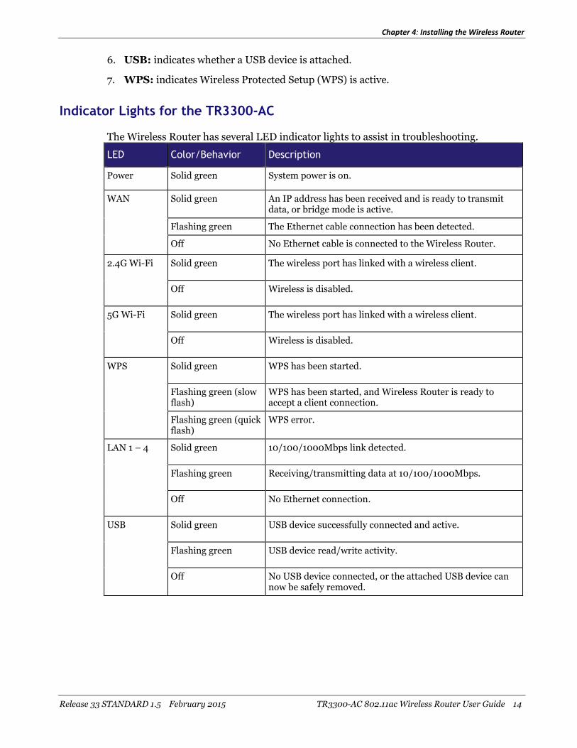
Indicator Lights for the TR3300-AC
The Wireless Router has several LED indicator lights to assist in troubleshooting.
LED Color/Behavior Description
Power Solid green System power is on.
WAN Solid green An IP address has been received and is ready to transmitdata, or bridge mode is active.
Flashing green The Ethernet cable connection has been detected.
Off No Ethernet cable is connected to the Wireless Router.
2.4G Wi-Fi Solid green The wireless port has linked with a wireless client.
Off Wireless is disabled.
5G Wi-Fi Solid green The wireless port has linked with a wireless client.
Off Wireless is disabled.
WPS Solid green WPS has been started.
Flashing green (slowflash)
WPS has been started, and Wireless Router is ready toaccept a client connection.
Flashing green (quickflash)
WPS error.
LAN 1 – 4 Solid green 10/100/1000Mbps link detected.
Flashing green Receiving/transmitting data at 10/100/1000Mbps.
Off No Ethernet connection.
USB Solid green USB device successfully connected and active.
Flashing green USB device read/write activity.
Off No USB device connected, or the attached USB device cannow be safely removed.

Chapter 4: Installing the Wireless Router
Release 33 STANDARD 1.5 February 2015 TR3300-AC 802.11ac Wireless Router User Guide 15
Rear Panel
The rear of the Wireless Router has the following connectors and controls:
1. Reset button: resets the Wireless Router as if you power cycled the unit. Use apointed non-metallic object to press this button.
Note: If you hold the Reset button for more than five seconds, the Wireless Router will bereset to the factory default settings and will reboot.
2. WPS Button: begins associating the Wireless Router with a wireless device.
3. USB: USB host connector - future support for external USB devices.
4. Ethernet (1 - 4): connectors for use with a computer LAN port.
5. WAN: connector for the modem.
6. Power: connector for the power cord.
Selecting an Installation Location
There are a number of factors to consider when choosing a location to install the WirelessRouter:

Chapter 4: Installing the Wireless Router
Release 33 STANDARD 1.5 February 2015 TR3300-AC 802.11ac Wireless Router User Guide 16
Is an AC outlet available nearby? For best results, the outlet should not be switched andshould be close enough to the Wireless Router that extension cords are not required.
Is the modem nearby? Can you easily run cables between the Wireless Router’s locationand the modem?
If you are connecting devices to the Ethernet ports, can you easily run cables betweenthe Wireless Router’s location and those devices?
If you want to install the Wireless Router on a desktop, is there enough space on eitherside to keep the vents clear? Blocking the vents may cause overheating.
How close are the wireless devices? In general, the Wireless Router should be locatedclose to the center of the user sphere. The Wireless Router wireless connection range istypically 100–200 feet (30m–65m) for 2.4 GHz signals and less for 5 GHz signals. Anumber of factors can affect connection range, as described below.
Desktop Mounting Instructions
Position the Wireless Router so that:
air flows freely around it
the back faces the nearest wall
it will not fall to the floor if bumped or moved
the sides of the unit are not blocked.
Note: Clean the Wireless Router using only a clean, slightly moistened, cloth. Do not useaerosols in the vicinity of the Wireless Router.
Factors Affecting Wireless Range
A number of factors can affect the usable range for wireless connections.
Increases range Locating the unit centrally
Creating as much "line-of-sight" as possible with client devices
Decreases range Metal or concrete walls between the Wireless Router and otherdevices
Large metal appliances, aquariums, or metal cabinets between theWireless Router and other devices
Interference and RF noise (2.4 GHz wireless phones, microwaveovens, wireless speaker/receiver systems, or other wirelessnetworks)
Placing the device in a cabinet or other enclosed space
Note: Decreasing the range of the wireless network may be beneficial, as long as thedecreased range is sufficient for your needs. By limiting the network’s range, you reduceinterference with other networks and make it harder for unwanted users to find and connect to thenetwork.

Chapter 4: Installing the Wireless Router
Release 33 STANDARD 1.5 February 2015 TR3300-AC 802.11ac Wireless Router User Guide 17
Note: Setting the transmit power level to High increases the range. Setting it to Medium orLow decreases the range proportionately. Medium or Low may be more appropriate for high-density residential locations.
Ethernet or Wireless?
There are two ways to connect the computer (or other equipment) to the Wireless Router.The following will help you decide which is best for you:
Ethernet
Ethernet is a standard method of connecting two or more computers into a Local AreaNetwork (LAN). You can use the Ethernet connection if the computer has built-in Ethernethardware. The TR3300-AC provides support for up to four such connected devices.
Note: To connect more than four computers to the TR3300-AC through the Ethernet ports,you need an Ethernet switch (available at computer retailers).
The Wireless Router package comes with one 4-foot (1.2m) Ethernet cable (the connectorslook like wide telephone connectors); you can purchase more cables if necessary at acomputer retailer. If you are connecting the Wireless Router directly to a computer, or toan Ethernet switch with a cross-over switch, ask for Category 5e (CAT5e) straight-throughcable. CAT5e cable is required for gigabit Ethernet (Gig-E), not regular CAT5 cable.
Wireless
Wireless access lets you connect additional (wireless-capable) devices to the WirelessRouter. The 802.11 wireless LAN standard allows one or more computers to access theTR3300-AC using a wireless (radio) signal. These connections are in addition to theconnections supported via Ethernet.
Note: You can use the wireless connection if the computer has a built-in or aftermarketplug-in wireless adapter. To learn more about which wireless hardware works best with thecomputer, see your computer dealer.
Both
If you have two or more computers, you can use Ethernet for up to four devices andwireless for the others. To connect five or more computers to the Ethernet ports, you willneed an Ethernet switch (available at computer retailers.)

Chapter 4: Installing the Wireless Router
Release 33 STANDARD 1.5 February 2015 TR3300-AC 802.11ac Wireless Router User Guide 18
Connecting the Wireless Router
1. Unplug the power to turn off the modem.
2. Connect one end of the Ethernet cable (included) to the modem, and the other end tothe WAN port on the Wireless Router.
3. Reconnect the plug on the modem to turn the modem back on. Wait approximately 2minutes to allow the modem to fully power up.
4. Connect the power adapter (included) to the power connector on the back of theWireless Router, and then connect the power adapter to an available AC outlet. Waituntil the 2.4G and 5G LEDs on the front panel of the Wireless Router turn solid green.
5. To manage the setup of the Wireless Router, you can use a second Ethernet cable (notprovided) to connect a computer to an available LAN port on the TR3300-AC, or youcan connect wirelessly by using the preset wireless security settings printed on thesecurity label located on the bottom of the Wireless Router.
6. Open a browser on the computer to access the management interface of the WirelessRouter. If the webpage does not display correctly, try another browser. See Accessingthe Configuration Interface (page 19) for more information.
Note: In some cases, the service provider may redirect the browser to their welcome page sothat you can establish new service. This step may be required before you can manage the TR3300-AC configuration settings.
Configuring the Wireless Connection
The TR3300-AC ships with a secure SSID that is unique for every device. Wi-Fi networkinformation is located on the label on the bottom of the Wireless Router. You shouldconfigure the Wireless Router's wireless settings.
Note: At a minimum, you should set a login password and set up wirelesssecurity. Refer to Configuring the Wireless Network (page 20) for complete instructions onconfiguring the wireless connection.
Release 33 STANDARD 1.5 February 2015 TR3300-AC 802.11ac Wireless Router User Guide 19
Chapter 5
Basic Configuration
The Wireless Router ships with a basic factory default configuration that should allow youto immediately access the Internet after installing the hardware according to the User’sGuide.
If you need to modify the Wireless Router's default basic settings, or if you want toconfigure advanced settings, refer to the appropriate instructions in this document.
As a minimum, it is recommended that you:
Change the default login password
Change the default wireless network name, also called the Service Set Identifier (SSID)
Wireless LAN Default Security Setting: The Wireless Router ships withwireless LAN security set by default. See the security label on the product forthe factory security settings: network name (SSID), encryption method,network key, and WPS PIN.
If you need to modify the Wireless Router’s default wireless security settings, or if you wantto configure any other settings, refer to the appropriate instructions in this document.
Note: You must set up the computer and other client devices to work with the securitysettings on the Wireless Router. Refer to the documentation for the client device for instructions onsetting security. If the computer or client device supports Wi-Fi Alliance WPS (Wireless ProtectedSetup), activate WPS on the computer or client device and the Wireless Router simultaneously toeasily set up the system security.
Accessing the Configuration Interface
Perform the following steps to access the configuration interface.
1. If security has been properly set up on the computer to access the wireless LAN on theWireless Router, use the connection utility for the operating system to connect to thewireless LAN using its network name (SSID), as shown on the security label.
Note: If you cannot access the wireless LAN, you must first establish a wired Ethernetconnection between the computer and the Wireless Router.
2. In the web browser, open the page http://192.168.1.1/ to access the Wireless Routersetup.
The Login screen displays.
3. Enter the user name and password and click Apply to log in.
Note: The default user name is "admin". The default password is "password", in lower caseletters.

Chapter 5: Basic Configuration
Release 33 STANDARD 1.5 February 2015 TR3300-AC 802.11ac Wireless Router User Guide 20
The Basic Wireless Settings screen displays.
4. Set basic setup configuration parameters as required for the system.
Note: Most configuration parameters that you may want to set can be accessed on the BasicWireless Settings screen or on the LAN Setup or Wireless tabs.
Configuring the Wireless Network
Perform the following procedures to make the basic configuration settings for the wirelessnetwork.
Enabling or Disabling the Wireless Network.
Perform the following steps to enable the wireless network.
1. Access and log into the configuration interface.
2. Click the Basic Setup tab.
3. Click the Enable Wireless checkbox in either the Wireless 2.4 GHz section or theWireless 5 GHz section to enable wireless networking for that frequency.
4. Click Apply.
Changing the Login Password
You should change the login password to something other than the default password.
Note: The default user name is "admin," the default password is "password" (both lowercase).
Perform the following steps to change the password.
1. Access and log into the configuration interface via a direct wired Ethernet or wirelessconnection.
2. Click the Utilities tab.
3. Click System Settings in the side menu.
4. Enter the old password in the Current Password field.
5. Enter the new password in both the New Password and Confirm New Passwordfields.
Note: Passwords are case-sensitive. Valid characters are the numbers 0 to 9, the letters athrough z and A through Z, and printable special characters (such as $, !, ?, &, #, @, and others.)
6. Click Apply.
7. Record the new passwords here:
2.4 GHz Password: ___________________________________

Chapter 5: Basic Configuration
Release 33 STANDARD 1.5 February 2015 TR3300-AC 802.11ac Wireless Router User Guide 21
5 GHz Password: _____________________________________
Changing the Default Wireless Network Name (SSID)
Perform the following steps to change the wireless 2.4 GHz and/or wireless 5 GHz networkname.
1. Access and log into the configuration interface.
2. Click the Basic Setup tab.
3. Enter a unique user friendly name to identify the wireless network in the WirelessNetwork Name (SSID) field under either Wireless 2.4 GHz or Wireless 5 GHz.
Note: This name is also referred to as the Service Set Identifier (SSID). The name can be upto 32 characters long. Do not duplicate any other SSID names that may be operating in the area.
4. Click Apply at the bottom of the screen.
5. Record the new network names here:
2.4 GHz Network name (SSID): ______________________________
5 GHz Network name (SSID): ________________________________
Configuring Wi-Fi Protected Setup (WPS)
WPS is a standard method for easily configuring a secure connection between the WirelessRouter and computers or other wireless devices (known as enrollees) that support WPS.When WPS is enabled you can attach other wireless devices by pressing the WPS buttonson the device (if equipped) and on the Wireless Router, or by entering the enrollee’s PINand then clicking the Start WPS Association icon.
Perform the following steps to enable the wireless network.
1. Access and log into the configuration interface.
2. Click the Basic Setup tab.
3. Click WPS Settings in the side menu.
4. Click the Wi-Fi Protected Setup (WPS) Enable checkbox and click Apply toenable WPS on the system.
5. a) If the client device has a WPS button, press the WPS buttons on the client deviceand on the Wireless Router simultaneously to start the WPS association.
b) If the client device has a PIN number, enter the enrollee’s PIN in the Enrollee PINCode field, and then click the Start WPS Association icon. Enter the WirelessRouter’s PIN code in the Device PIN Code field if requested during connection.
6. If the connection is successful, the WPS indicator light on the Wireless Router stopsflashing and remains lit. If unsuccessful, the WPS light continues to flash for up to twominutes (indicating that it’s ready to accept a client connection) and then turns off. Ifthe WPS light turns off, start the association process over.
Chapter 5: Basic Configuration
Release 33 STANDARD 1.5 February 2015 TR3300-AC 802.11ac Wireless Router User Guide 22
Setting Up the WAN Connection
A Dynamic or DHCP (Dynamic Host Configuration Protocol) connection is the mostcommonly used WAN connection type.
Note: Do not change this setting unless your Internet Service Provider tells you to useanother connection type.
Perform the following steps to change the connection type.
1. Access and log into the configuration interface.
2. Click the WAN Setup tab.
3. Click Dynamic, Static, Dynamic (IPV6),or Static (IPV6) in the side menu todisplay the appropriate screen for configuring that type of WAN connection.
4. Set the required configuration parameters for the connection type you selected asprovided by your service provider.
Note: Refer to WAN Setup in Wireless Router Configuration Screen Descriptions (page 29)for specific instructions on setting the various connection type configuration parameters.
5. Click Apply at the bottom of the screen.
Release 33 STANDARD 1.5 February 2015 TR3300-AC 802.11ac Wireless Router User Guide 23
Chapter 6
Advanced Configuration Options
This section explains how to use the most common advanced configuration options for theWireless Router in the following areas:
LAN Setup
Wireless Setup
Firewall
Utilities
Note: Refer to Wireless Router Configuration Screen Descriptions (page 29) for additionaladvanced configuration options.
LAN Setup – Configuring DHCP
DHCP (Dynamic Host Protocol Configuration) is enabled by default on the WirelessRouter which allows the Wireless Router to act as a DHCP server and automatically assignan IP address to each device on the network.
DHCP is a set of rules used by devices such as a computer, Wireless Router, or networkadapter to allow the device to request and obtain an IP address from a server whichmaintains a list of addresses available for use. The DHCP server ensures that all IPaddresses are unique, e.g., no IP address is assigned to a second device while the firstdevice's assignment is valid (its lease has not expired).
Without DHCP, the IP addresses must be entered manually at each computer or device anda new IP address must be entered each time it moves to a new location on the network.
Perform the following steps to configure DHCP.
1. Access and log into the configuration interface.
2. Click the LAN Setup tab.
3. Click LAN Settings or LAN Settings (IPV6) in the side menu to display the LANSettings screen.
4. Click the Enable DHCP Server or Enable DHCP Server (IPV6) checkbox underDHCP Server Settings.
5. Enter the Start IP Address and End IP Address for the range of IP addresses that theDHCP Server will be allowed to assign to a network device.
6. Enter the Lease Time in seconds before the assigned IP address will expire. (After thelease time is up, the user is automatically assigned a new dynamic IP address.)
Note: Refer to LAN Setup (page 35) for specific instructions on setting the various DHCPconfiguration parameters.
Chapter 6: Advanced Configuration Options
Release 33 STANDARD 1.5 February 2015 TR3300-AC 802.11ac Wireless Router User Guide 24
7. Click Apply at the bottom of the screen.
LAN Setup – Adding and Deleting DHCP Clients
The Client List screen shows the host name, IP address, and MAC address of eachcomputer that is connected to the network. If a computer does not have a specified hostname, then the host name field will be blank.
Perform the following steps to configure the DHCP Clients.
1. Access and log into the configuration interface.
2. Click the LAN Setup tab.
3. Click Client List in the side menu to display the Client List screen.
4. Click Add to add a reserved IP client. Select an existing DHCP client and then clickDelete to delete the client. Click Refresh to update the Clients List.
LAN Setup – Selecting the NAT Mode
NAT (Network Address Translation) allows the Wireless Router to manipulate IPaddresses so that just one single IP address can represent an entire group of computers onthe network and let them all communicate with the Internet. This conserves IP addressesand is necessary since there are a limited number of available IP addresses for use.
Perform the following steps to select the NAT Mode.
1. Access and log into the configuration interface.
2. Click the LAN Setup tab.
3. Click LAN Settings in the side menu to display the LAN Settings screen.
4. Select the NAT Mode from the NAT Mode field drop-down list. The optional modesare:
Bridged - Data will pass through the device directly without any routing.
Routed with NAT - Data will be routed by the device and all the outgoing packets willbe NATed.
Routed without NAT - Data will be routed by the device but all the outgoing packetswill not be NATed.
5. Click Apply at the bottom of the screen.
Note: A dialog box prompts you to restart the Wireless Router. Click OK to restart.
Wireless Setup – Setting the Wireless Mode
You can set the wireless mode to optimize performance based on the type of networkadapters being used by the network devices, e.g., 802.11b, 820.11g, and 802.11n. Select theproper mode to support all of the wireless devices that will connect to the Wireless Router.
Chapter 6: Advanced Configuration Options
Release 33 STANDARD 1.5 February 2015 TR3300-AC 802.11ac Wireless Router User Guide 25
Perform the following steps to set the wireless mode.
1. Access and log into the configuration interface.
2. Click the Wireless tab.
3. Click Basic Setup in the side menu to display the Advanced Settings screen.
4. Under Wireless 2.4 GHz or Wireless 5 GHz, select the proper mode from the WirelessMode drop-down list.
2.4 GHz Options: B only, G only, B/G mixed, and G/N mixed.
5 GHz Options: A only, A/N mixed, and A/N/AC mixed.
5. Click Apply at the bottom of the screen.
Note: Refer to Advanced (page 42) for instructions on setting additional advanced wirelessconfiguration parameters.
Note: If you have both A and B running in your network, then throughput on the entirewireless network will be reduced.
Firewall – General Firewall Configuration Settings
The Wireless Router is equipped with a firewall that will protect the network from a widearray of common Denial of Service (DoS) attacks, including Ping of Death (PoD) attacks.
You can disable the firewall function if needed. Turning off the firewall protection will notleave the network completely vulnerable to hacker attacks, but it is recommended that youenable the firewall whenever possible.
Perform the following steps to enable the firewall and make general firewall settings.
1. Access and log into the configuration interface.
2. Click the Firewall tab.
3. Click Firewall Settings in the side menu to display the Firewall Settings screen.
4. Check the Enable Firewall checkbox to enable the firewall on the network.
5. Click Apply at the bottom of the screen.
6. Click WAN Ping Blocking in the side menu to display the WAN Ping Blockingscreen.
7. Check the Block ICMP Ping Enable checkbox to protect against PoD attacks.
8. Click Apply at the bottom of the screen.
Firewall – Configuring a Virtual Server (Port Forwarding)
The port forwarding function forwards inbound traffic from the Internet to a specifiedsingle device on the network. Examples include allowing access to a web server on the

Chapter 6: Advanced Configuration Options
Release 33 STANDARD 1.5 February 2015 TR3300-AC 802.11ac Wireless Router User Guide 26
network, peer-to-peer file sharing, applications that allow remote access to the computer,some gaming and videoconferencing applications, and others.
If you have a server in the network that you want to make available to the general Internet,you can configure a virtual server. The firewall passes requests from the Internet to thedesignated computer on the network. This function works by allowing you to routeexternal (Internet) calls for services such as a web server (port 80), FTP server (Port 21), orother applications through the Wireless Router to the internal network.
Perform the following steps to configure a virtual server.
1. Access and log into the configuration interface.
2. Click the Firewall tab.
3. Click Virtual Servers in the side menu to display the Virtual Server Configurationscreen.
4. Select the type of server that you want to add from the Service List drop-down box.
5. Click Add to add that virtual server.
6. If necessary, adjust the following parameters for the server that you are adding.
Enable – Enable this virtual server
Description – Enter a name for the virtual server.
Inbound Port – Enter the inbound port range for the virtual server. It should be thesame range as the local port.
Type – Sets the format for the port. Options are TCP, UDP, or BOTH.
Private IP Address – Enter the IP address of the machine on the LAN that you wantthe connections to go to.
Private Port – Enter the private port range for the virtual server. It should be thesame range as the inbound port.
7. Click Apply to save your settings.
Note: To delete a virtual server, first select a virtual server in the list and then click Delete.
Firewall – Configuring DMZ for Gaming or Conferencing Applications
The DMZ feature allows you to specify one computer on the network to be placed outsideof the NAT firewall. This may be necessary if the NAT feature is causing problems with anapplication such as a game or video conferencing application.
Use this feature only on a temporary basis. The computer in the DMZ is not protected fromhacker attacks.
Perform the following steps to put a computer in the DMZ.
1. Access and log into the configuration interface.
2. Click the Firewall tab.

Chapter 6: Advanced Configuration Options
Release 33 STANDARD 1.5 February 2015 TR3300-AC 802.11ac Wireless Router User Guide 27
3. Click DMZ in the side menu to display the DMZ Settings screen.
4. Enter the following parameters.
Enable – Click this checkbox to enable DMZ on the network.
Static IP – Displays the static IP address.
Private IP – Enter the IP address of the computer to be placed in the DMZ. Be surethat the address is not in the range of addresses delivered by the DHCP server ifenabled. After placing the computer in the DMZ, all ports on the computer are open tothe Internet and not protected.
5. Click Apply at the bottom of the screen.
Note: To remove the computer from the DMZ, delete the entries and uncheck the EnableDMZ checkbox.
Utilities – Viewing Network System Information
You can view status and system information for the network on the System Informationscreen.
Perform the following steps to view system status information.
1. Access and log into the configuration interface.
2. Click the Utilities tab.
3. Click System Information in the side menu to display the System Informationscreen.
Note: Refer to System Information (page 51) for an explanation of the various statusinformation parameters.
Utilities – Restarting the Wireless Router
It may be necessary to restart (reboot) the Wireless Router if it begins working improperly.Restarting the Wireless Router will not delete any of the configuration settings.
Perform the following steps to restart the Wireless Router.
1. Access and log into the configuration interface.
2. Click the Utilities tab.
3. Click Restart Router in the side menu to display the Restart Router screen.
4. Click the Restart Router button to restart the Wireless Router.
Chapter 6: Advanced Configuration Options
Release 33 STANDARD 1.5 February 2015 TR3300-AC 802.11ac Wireless Router User Guide 28
Utilities – Reverting to Factory Default Settings
This function restores all of the Wireless Router’s configuration settings to the factorydefault setting. Perform the following steps to revert to factory default settings.
1. Access and log into the configuration interface.
2. Click the Utilities tab.
3. Click Factory Default in the side menu to display the Factory Defaults screen.
4. Click the Factory Defaults button to reset the Wireless Router to factory defaultsettings.
Utilities – Viewing the System Logs
The System Logs screen displays the system logs.
Perform the following steps to configure the system logs.
1. Access and log into the configuration interface.
2. Click the Utilities tab.
3. Click System Log in the side menu to display the System Logs.
When viewing the logs, click Refresh to update the list.
Utilities – DDNS
DDNS (Dynamic DNS) allows you to provide Internet users with a fixed domain name(instead of an IP address which may periodically change). This allows various locations onthe Internet to access the gateway and the applications that are set up in the gateway'svirtual servers without knowing your current IP address.
Requirements
In order to use DDNS you must first create an account with a DDNS provider. The DDNSprovider maps your chosen domain name to your IP address.
Once the account is established, perform the following steps to enable DDNS.
1. Access and log into the configuration interface.
2. Click the Utilities tab.
3. Click DDNS in the side menu to display the DDNS configuration screen.
4. Click the DDNS Enable checkbox.
Note: Refer to DDNS (page 55) for specific instructions on setting the various DDNSconfiguration parameters.
5. After setting the necessary configuration parameters, click Apply at the bottom of thescreen.

Release 33 STANDARD 1.5 February 2015 TR3300-AC 802.11ac Wireless Router User Guide 29
Chapter 7
Wireless Router Configuration Screen Descriptions
This section provides an overview of the ARRIS graphical user interface (GUI) WirelessRouter setup screens.
Each of the following tabs in the GUI and their individual sub-menus and configurationparameters are explained in detail:
Basic Setup
WAN Setup
LAN Setup
Wireless
StreamBoost
Firewall
Utilities
Basic Setup
Basic Wireless Settings
While the system has many configuration options, the options on this Basic Setup page arethose required by most users. Click the tabs to access the other configuration pages to setadvanced options. Hover the mouse pointer over the question mark icon next to an optionto view a description of that option. For changes to take effect, you must click Apply.

Chapter 7: Wireless Router Configuration Screen Descriptions
Release 33 STANDARD 1.5 February 2015 TR3300-AC 802.11ac Wireless Router User Guide 30
Wireless 2.4 GHz/Wireless 5 GHz:
Enable Wireless – Click this checkbox to enable the wireless network on the system.
Wireless Network Name (SSID)– Enter a user friendly name to identify the wirelessnetwork. This name is also referred to as the Service Set Identifier (SSID). The name canbe up to 32 characters long.
Password – Sets the Wi-Fi password. Use a password that will not be easy to guess.Passwords are case-sensitive. Valid characters are the numbers 0 to 9, the letters a throughz and A through Z, and printable special characters (such as $, !, ?, &, #, @, and others).You must click Apply to save the new password.
Note: You must be logged into the configuration interface via a direct wired Ethernetconnection to change the password.
WPS Settings
Wi-Fi Protected Setup (WPS) is the industry standard method to simplify the securitysetup and management of Wi-Fi networks. You can now easily set up and connect to aWPA-enabled 802.11 network with WPS-certified devices using either a PersonalInformation Number (PIN) or the Push Button Configuration (PBC) method. Legacydevices without WPS can be added to the network using the traditional manualconfiguration method.
WPS Enable/Disable:
Wireless 2.4 GHz/Wireless 5 GHz – Click the frequency for which you want to enable WPS.
Chapter 7: Wireless Router Configuration Screen Descriptions
Release 33 STANDARD 1.5 February 2015 TR3300-AC 802.11ac Wireless Router User Guide 31
WPS Enable – Click this checkbox to enable WPS on the system. WPS is a standardmethod for easily configuring a secure connection between the Wireless Router andcomputers or other wireless devices (known as enrollees) that support WPS. When WPS isenabled, you can attach other wireless devices by pressing the WPS buttons on the device(if equipped) and on the Wireless Router, or by entering the enrollee’s PIN and thenclicking the Start WPS Association icon.
PIN Method:
Enrollee PIN Code – If the client device has a WPS PIN number, enter it here, then clickEnroll.
Device PIN Code – Enter this code on the computer if requested during connection.
PBC Method:
Start PBC – Click to start the PBC connection process.
WAN Setup
Dynamic
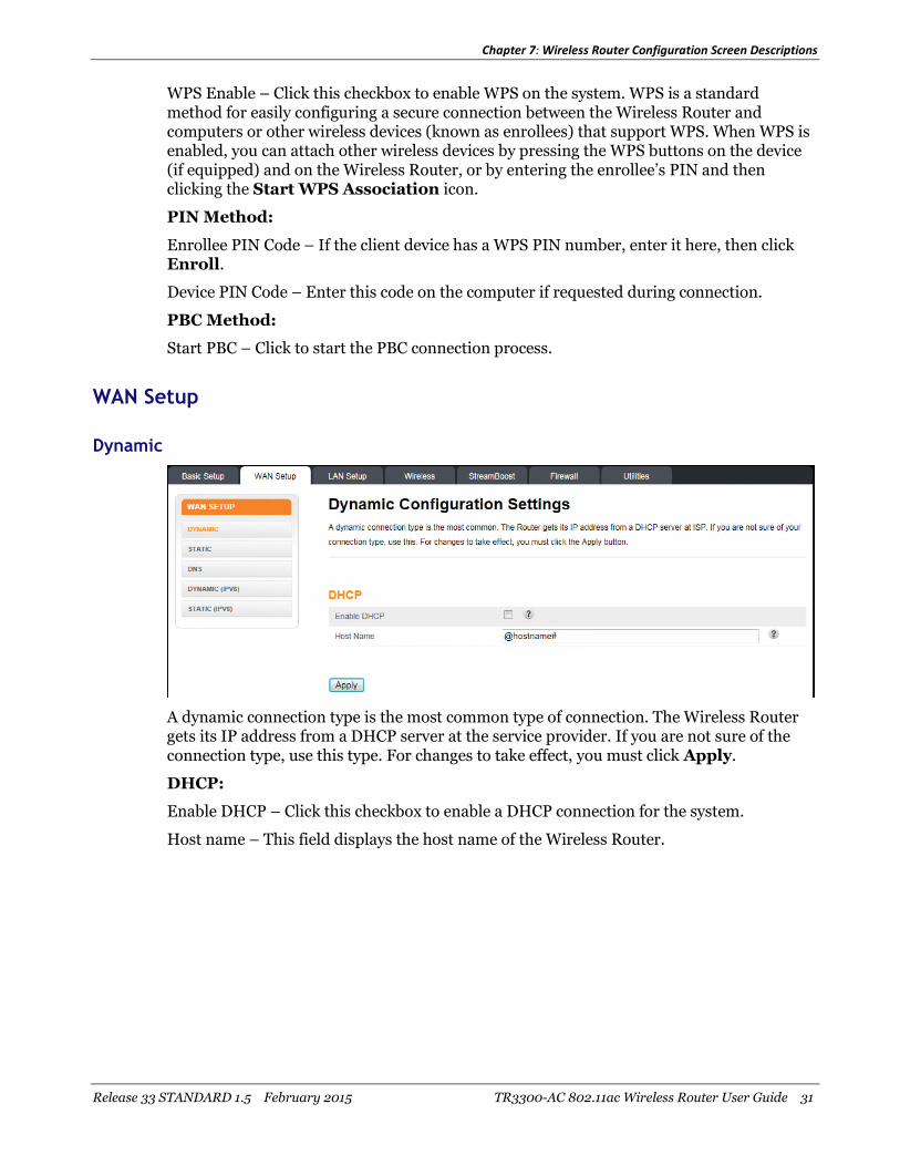
A dynamic connection type is the most common type of connection. The Wireless Routergets its IP address from a DHCP server at the service provider. If you are not sure of theconnection type, use this type. For changes to take effect, you must click Apply.
DHCP:
Enable DHCP – Click this checkbox to enable a DHCP connection for the system.
Host name – This field displays the host name of the Wireless Router.

Chapter 7: Wireless Router Configuration Screen Descriptions
Release 33 STANDARD 1.5 February 2015 TR3300-AC 802.11ac Wireless Router User Guide 32
Static
A static IP address connection type is less common than others and uses a permanent IPaddress to connect to the Internet. If your service provider gives you an IP address thatnever changes, then use this option. For changes to take effect, you must click Apply.
Static IP Settings:
Enable Static IP – Click this checkbox to enable a static IP address connection for thesystem.
IP Address – Enter the IP address assigned by your service provider or static IP operation.
Subnet Mask – Enter the subnet mask assigned for the device by your service provider orstatic IP operation.
Gateway Address – Enter the gateway address assigned for the device by your serviceprovider or static IP operation.
Click here to enter your DNS Settings – If your service provider gave you specific DNSsettings, click here to go to the DNS Settings screen to enter those settings.
DNS
If your service provider gave you specific DNS settings, use this screen to enter them.

Chapter 7: Wireless Router Configuration Screen Descriptions
Release 33 STANDARD 1.5 February 2015 TR3300-AC 802.11ac Wireless Router User Guide 33
DNS Settings
Automatic from ISP – Click this checkbox if the Wireless Router should automatically getits DNS settings from your service provider.
Primary DNS Server IP – Enter the IP address of the primary DNS server.
Secondary DNS Server IP – Enter the IP address of the secondary DNS server.
Dynamic (IPV6)
This screen enables a DHCPv6 configured IPV6 stack. A dynamic connection type is themost common type of connection.
The Wireless Router gets its IP address from a DHCP server at your service provider. If youare not sure of the connection type, use this type. For changes to take effect, you must clickApply.
Dynamic Configuration (IPV6):
Enable DHCP (IPV6) – Click this checkbox to enable a DHCP (IPV6) connection for thesystem.
IP Address V6 – This field displays the IPV6 address automatically assigned by the serviceprovider. An IPV6 address has eight groups of four hexadecimal digits (0-9, a-f). Thegroups are separated by colons (:) e.g. 2001:0db8:85a3:0000:0000:8a2e:0370:7334. Adouble colon (::) is shorthand for an address of all zeros.
Delegated Prefix – This field displays the assigned IPV6 prefix to be used by addressesallocated in the local network.
Delegated Prefix Length – This field displays the assigned IPV6 prefix length.
IPV6 Gateway Address – This field displays the gateway address.

Chapter 7: Wireless Router Configuration Screen Descriptions
Release 33 STANDARD 1.5 February 2015 TR3300-AC 802.11ac Wireless Router User Guide 34
Static (IPV6)
This screen enables a statically configured IPV6 stack. A static IP address connection typeis less common than others and uses a permanent IP address to connect to the Internet. Ifyour service provider gives you an IP address that never changes, then use this option. Forchanges to take effect, you must click Apply.
Static IP Settings (IPV6):
Enable Static IPV6 - Click this checkbox to enable a static IPV6 address connection for thesystem.
IP Address V6– Enter the IPV6 address assigned by your service provider or static IPoperation. An IPV6 address has eight groups of four hexadecimal digits (0-9, a-f). Thegroups are separated by colons (:) e.g. 2001:0db8:85a3:0000:0000:8a2e:0370:7334. Adouble colon (::) is shorthand for an address of all zeros.
Prefix Length (IPV6) – The length of the network portion of this address.
IPV6 Gateway Address – Enter the gateway address assigned for the device by your serviceprovider or static IP operation.
Primary DNS Server (IPV6) – Enter the IPV6 address of the primary DNS server. Yourservice provider will provide this information.
Secondary DNS Server (IPV6) – Enter the IPV6 address of the secondary DNS server. Yourservice provider will provide this information.
Domain Name – The entry here will be displayed as the domain name on the clientdevices. It can be specified by your service provider or by you.
Delegated Prefix – The network portion of the IPV6 addresses to be allocated to localclients.
Delegated Prefix Length – The length of the network portion of the IPV6 addresses to beallocated to local clients.

Chapter 7: Wireless Router Configuration Screen Descriptions
Release 33 STANDARD 1.5 February 2015 TR3300-AC 802.11ac Wireless Router User Guide 35
LAN Setup
LAN Settings
You can make changes to the Local Area Network (LAN) configuration here. For changes totake effect, you must click Apply.
Note: You can optionally set up the system so that there is more than one LAN in thenetwork. This is most useful for commercial applications, not home use. All of the "LAN Setup" and"Wireless Setup" configuration parameters can be set independently for each individual LAN.
LAN IP Settings:
IP Address – This field displays the IP address of the LAN.
Subnet Mask – This field displays the subnet mask of the LAN.
DHCP Server Settings:
Enable DHCP Server – Click this checkbox to enable the use of a Dynamic HostConfiguration Protocol (DHCP) Server on the network.

Chapter 7: Wireless Router Configuration Screen Descriptions
Release 33 STANDARD 1.5 February 2015 TR3300-AC 802.11ac Wireless Router User Guide 36
DHCP is a set of rules used by devices such as a computer, router, or network adapter toallow the device to request and obtain an IP address from a server which maintains a list ofaddresses available for use.
The DHCP server ensures that all IP addresses are unique, e.g., no IP address is assigned toa second device while the first device's assignment is valid (its lease has not expired).
Without DHCP, the IP addresses must be entered manually at each computer in anorganization, and a new IP address must be entered each time a computer moves to a newlocation on the network.
Start IP Address/End IP Address – Enter the range of IP addresses that the DHCP Serverwill be allowed to assign to a network device.
Lease Time – Enter the lease time in seconds before the assigned IP address will expire.(After the lease time is up, the user is automatically assigned a new dynamic IP address.)
A "lease" is the amount of time that a given IP address will be valid for a computer or othernetwork device. The lease time can vary depending on how long a user is likely to requirethe Internet connection at a particular location. Using very short leases, DHCP candynamically reconfigure networks where there are more computers than available IPaddresses, such as educational environments.
Domain Name – This field displays the domain name.
NAT:
NAT Mode – Select the NAT Mode.
Routed with NAT - Data will be routed by the device and all the outgoing packets willbe NATed.
Routed without NAT - Data will be routed by the device but all the outgoing packetswill not be NATed.
Bridged - Data will pass through the device directly without any routing.
UPnP:
Enable UPnP – Click this checkbox to enable UPnP (Universal Plug and Play) on thesystem.
Advertisement Time To Live – Enter the maximum number of hops that each UPnP packetcan be sent before it is disregarded. The default value is 4, which should be acceptable formost home networks.
IGMP Proxy:
Enable IGMP Proxy – Click this checkbox to enable the IGMP (Internet GroupManagement Protocol) proxy on the system.

Chapter 7: Wireless Router Configuration Screen Descriptions
Release 33 STANDARD 1.5 February 2015 TR3300-AC 802.11ac Wireless Router User Guide 37
LAN Settings (IPV6)
This screen configures LAN side support for IPV6. You can make changes to the LocalArea Network (LAN) configuration here. For changes to take effect, you must click Apply.
Note: You can optionally set up the system so that there is more than one LAN in thenetwork. This is most useful for commercial applications not home use. All of the "LAN Setup" and"Wireless Setup" configuration parameters can be set independently for each individual LAN.
LAN Settings (IPV6):
IP Address (IPV6) – This field displays the IPV6 address of the LAN. An IPV6 address haseight groups of four hexadecimal digits (0-9, a-f). The groups are separated by colons (:)e.g. 2001:0db8:85a3:0000:0000:8a2e:0370:7334. A double colon (::) is shorthand for anaddress of all zeros.
Prefix Length V6 – Length of the network portion of the IPV6 address.
Link Local Address (IPV6) – IPV6 address that can be used only on this network.
DHCP Server Settings (IPV6):
Enable DHCP Server (IPV6) – Click this checkbox to enable the use of a V6 Dynamic HostConfiguration Protocol (DHCP) Server on the network.
DHCP is a set of rules used by devices such as a computer, router, or network adapter toallow the device to request and obtain an IP address from a server which maintains a list ofaddresses available for use.
The DHCP server ensures that all IP addresses are unique, e.g., no IP address is assigned toa second device while the first device's assignment is valid (its lease has not expired).

Chapter 7: Wireless Router Configuration Screen Descriptions
Release 33 STANDARD 1.5 February 2015 TR3300-AC 802.11ac Wireless Router User Guide 38
Without DHCP, the IP addresses must be entered manually at each computer in anorganization, and a new IP address must be entered each time a computer moves to a newlocation on the network.
Start IP Address (IPV6)/End IP Address (IPV6) – Enter the range of IPV6 addresses thatthe DHCP Server will be allowed to assign to a network device.
Lease Time V6 – Enter the lease time in seconds before the assigned IPV6 address willexpire. (After the lease time is up, the user is automatically assigned a new dynamic IPaddress.)
A "lease" is the amount of time that a given IP address will be valid for a computer or othernetwork device. The lease time can vary depending on how long a user is likely to requirethe Internet connection at a particular location. Using very short leases, DHCP candynamically reconfigure networks where there are more computers than available IPaddresses, such as educational environments.
DHCP Relay Settings (IPV6):
Enable DHCP Relay (IPV6) – Click this checkbox to enable DHCP Relay functionality onthe system.
Client List
This page shows the host name, IP address, and MAC address of each computer that isconnected to the network. If a computer does not have a specified host name, then thehost name field will be blank.
Note: You can optionally set up the system so that there is more than one LAN in thenetwork. This is most useful for commercial applications not home use. All of the "LAN Setup" and"Wireless Setup" configuration parameters can be set independently for each individual LAN.
Static Client List:
Click Add to create a new fixed client lease.

Chapter 7: Wireless Router Configuration Screen Descriptions
Release 33 STANDARD 1.5 February 2015 TR3300-AC 802.11ac Wireless Router User Guide 39
IP Address – Enter the client’s IP address.
Name – Enter a name for the client.
MAC Address – Enter the client’s MAC address.
Select a client and then click Delete to delete the client lease.
Attached Client List:
Click Refresh to update the client list.
Wireless
Basic Setup
While the system has many configuration options, the options on this Basic Setup page arethose required by most users. Click the tabs to access the other configuration pages to set
Chapter 7: Wireless Router Configuration Screen Descriptions
Release 33 STANDARD 1.5 February 2015 TR3300-AC 802.11ac Wireless Router User Guide 40
advanced options. Hover the mouse pointer over the question mark icon next to an optionto view a description of that option. For changes to take effect, you must click Apply.
Note: You can optionally set up the system so that there is more than one LAN in thenetwork. This is most useful for commercial applications not home use. All of the "LAN Setup" and"Wireless Setup" configuration parameters can be set independently for each individual LAN.
Wireless 2.4 GHz/Wireless 5 GHz:
Enable Wireless – Click this checkbox to enable the wireless network on the system.
Channel – Sets a communications channel for the Wireless Router. The default setting is"Auto", in which the Wireless Router selects a channel with the least amount ofinterference to use. For 2.4 GHz, if you manually select a channel, it’s best to choosechannel 1, 6, or 11, since these channels do not overlap. If another unit is operating in thearea, choose a channel that is farthest away from the channel that unit uses. For example,if one is using channel 11, set yours to channel 1. For 5 GHz choose a channel that isfarthest away from the channel used by any other unit operating in the area. If youexperience interference or poor performance on a particular channel, try a differentchannel.
Wireless Network Name (SSID) – Enter a user friendly name to identify the wirelessnetwork. This name is also referred to as the Service Set Identifier (SSID). The name canbe up to 32 characters long.
Wireless Mode – Sets the wireless mode. 2.4 GHz Options are: B/G mixed, B only, G only,and G/N mixed. 5 GHz Options are: A only, A/N mixed, and A/N/AC mixed. Select theproper mode to support all of the wireless devices that will connect to the Wireless Router.(802.11b supports bandwidth up to 11 Mb/s. 802.11g supports bandwidth up to 54 Mb/s.802.11n supports bandwidth up to 300 Mb/s. 802.11ac support bandwitdh up to 1.3Gb/s.)
Channel Bandwidth – Sets the 802.11n Channel Bandwidth. Options are 20 MHz, 40MHz,20/40 MHz, or 80MHz (5 GHz only). The default setting is 20/40 MHz.
Broadcast Network Name (SSID) – Click this checkbox to allow the SSID to be broadcastby the Wireless Router. If enabled, the SSID could be obtained allowing unauthorizedaccess to the network. If you would like others not to see the access point, uncheck thecheckbox to hide the SSID.
AP Isolation – Click this checkbox to enable AP isolation. When enabled each of thewireless clients will be in its own virtual network and will not be able to communicate withone another. This may be useful if you have many guests using the network.
Enable WMM – Click this checkbox to enable Wi-Fi Multimedia (WMM) functionality.Enabling WMM can help control latency and jitter when transmitting multimedia contentover a wireless connection. Disabling WMM will reduce wireless performance in 802.11nmode.
This quality of service mechanism uses four access categories, which in order of priorityare: voice, video, best effort, and background. This ensures that applications with lowtolerance for latency and jitter are treated with higher priority than less-sensitive dataapplications. WMM sets different wait times for the four categories in order to providepriority network access for applications that are less tolerant of packet delays.
Security Mode – Sets the security mode for the Wireless Router. Can be set toWPA/WPA2-PSK (Wi-Fi Protected Access/ Wi-Fi Protected Access 2 – Pre-Shared Key)(most compatible); WPA2-PSK (Wi-Fi Protected Access 2 – Pre-Shared Key)
Chapter 7: Wireless Router Configuration Screen Descriptions
Release 33 STANDARD 1.5 February 2015 TR3300-AC 802.11ac Wireless Router User Guide 41
(recommended); WPA2-Enterprise; or WPA/WPA2-Enterprise. 802.11n performance isonly available in WPA2.
Pre-Shared Key - Sets the WPA Pre-Shared Key. This text string is used to generate aunique set of encryption keys for the network. Enter a text string in this field. The key canbe either ASCII (text) or Hex (hexadecimal). An ASCII text key can be from 8 to 63characters long. Valid characters are numbers "0" through "9" and letters "a" through "z",and printable special characters (such as $, !, ?, &, #, @, and others). A hexadecimal keymust be 64 characters long. Valid characters are numbers "0" through "9" and letters "a"through "f".
Guest Access
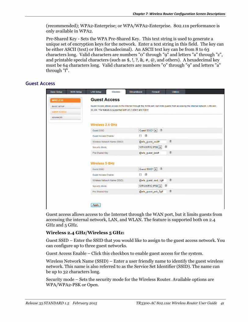
Guest access allows access to the Internet through the WAN port, but it limits guests fromaccessing the internal network, LAN, and WLAN. The feature is supported both on 2.4GHz and 5 GHz.
Wireless 2.4 GHz/Wireless 5 GHz:
Guest SSID – Enter the SSID that you would like to assign to the guest access network. Youcan configure up to three guest networks.
Guest Access Enable – Click this checkbox to enable guest access for the system.
Wireless Network Name (SSID) – Enter a user friendly name to identify the guest wirelessnetwork. This name is also referred to as the Service Set Identifier (SSID). The name canbe up to 32 characters long.
Security mode – Sets the security mode for the Wireless Router. Available options areWPA/WPA2-PSK or Open.
Chapter 7: Wireless Router Configuration Screen Descriptions
Release 33 STANDARD 1.5 February 2015 TR3300-AC 802.11ac Wireless Router User Guide 42
Pre-Shared Key – Sets the WPA Pre-Shared Key. This text string is used to generate aunique set of encryption keys for the network. Enter a text string in this field. The key canbe either ASCII (text) or Hex (Hexadecimal). An ASCII text key can be from 8 to 63characters long. Valid characters are numbers ‘0’ through ‘9’ and letters ‘a’ through ‘z’ aswell as most other characters. A hexadecimal key must be 64 characters long. Validcharacters are numbers ‘0’ through ‘9’ and letters ‘a’ through ‘f’.
Advanced
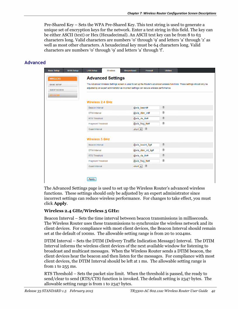
The Advanced Settings page is used to set up the Wireless Router’s advanced wirelessfunctions. These settings should only be adjusted by an expert administrator sinceincorrect settings can reduce wireless performance. For changes to take effect, you mustclick Apply.
Wireless 2.4 GHz/Wireless 5 GHz:
Beacon Interval – Sets the time interval between beacon transmissions in milliseconds.The Wireless Router uses these transmissions to synchronize the wireless network and itsclient devices. For compliance with most client devices, the Beacon Interval should remainset at the default of 100ms. The allowable setting range is from 20 to 1024ms.
DTIM Interval – Sets the DTIM (Delivery Traffic Indication Message) Interval. The DTIMInterval informs the wireless client devices of the next available window for listening tobroadcast and multicast messages. When the Wireless Router sends a DTIM beacon, theclient devices hear the beacon and then listen for the messages. For compliance with mostclient devices, the DTIM Interval should be left at 1 ms. The allowable setting range isfrom 1 to 255 ms.
RTS Threshold – Sets the packet size limit. When the threshold is passed, the ready tosend/clear to send (RTS/CTS) function is invoked. The default setting is 2347 bytes. Theallowable setting range is from 1 to 2347 bytes.

Chapter 7: Wireless Router Configuration Screen Descriptions
Release 33 STANDARD 1.5 February 2015 TR3300-AC 802.11ac Wireless Router User Guide 43
Fragment Threshold – Sets the fragmentation threshold. This threshold should be set toequal the maximum Ethernet frame size allowable on the link including overhead. Settinga lower threshold can damage data throughput since large frames could be fragmentedand/or collisions could occur. The default setting is 2346. The allowable setting range isfrom 256 to 2346 bytes.
Guard Interval – The spacing between transmission of symbols in nanoseconds. Can beset to short or long. Select short to provide higher throughput in networks where thecoverage distance is small (indoors). Select long to provide higher throughput in networkswhere the coverage distance is large (outdoors).
StreamBoost
StreamBoost Settings
The StreamBoost Settings screen lets users configure the StreamBoost Quality of Service(QoS) settings. StreamBoost is used to improve the online experience for connected clientsbased on the devices they use and the applications they are running. From this screen, theadministrator can control and test the throughput limits in the downstream and upstreamdirections.
StreamBoost Settings:
StreamBoost Enable – Click this checkbox to enable StreamBoost technology.
Auto Bandwidth Detection – Click this checkbox to enable Auto Bandwidth Detection.
Up Limit (Mbps) – Enter the amount of bandwidth (in megabits per second) that you wantto reserve for upstream (outgoing) traffic.
Down limit (Mbps) – Enter the amount of bandwidth (in megabits per second) that youwant to reserve for downstream (incomng) traffic.
Bandwidth Test – Click this button to run the bandwidth test.

Chapter 7: Wireless Router Configuration Screen Descriptions
Release 33 STANDARD 1.5 February 2015 TR3300-AC 802.11ac Wireless Router User Guide 44
Keep StreamBoost Up to Date:
Enable Automatic Update – Click this checkbox to enable automatic StreamBoost updatesduring the initial 2-year manufacturer service term. The service term will begin on the dateof manufacture and run for three years or until April 1st, 2017, whichever comes first.(After the 2-year period, the manufacturer may make further updates available viafirmware updates.) StreamBoost updates may improve the Wireless Router's Internettraffic management capabilities through better traffic identification and bandwidthmanagement techniques. In exchange, the Wireless Router will provide anonymous,performance-related information to the StreamBoost server for improved futureStreamBoost service.
Priorities
The Priorities screen lets you set bandwidth priority at the connected device level to ensurethat the most important client devices have access to the bandwidth they need to performwell. Use the Up and Down buttons to change the priority of a device in the list. ClickApply to save your settings.

Chapter 7: Wireless Router Configuration Screen Descriptions
Release 33 STANDARD 1.5 February 2015 TR3300-AC 802.11ac Wireless Router User Guide 45
STAT: Downloads
The Top By Downloads screen shows how bandwidth is being used in the local network ona per-device and per-application level.
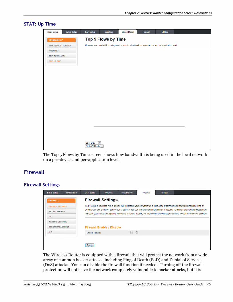
Chapter 7: Wireless Router Configuration Screen Descriptions
Release 33 STANDARD 1.5 February 2015 TR3300-AC 802.11ac Wireless Router User Guide 46
STAT: Up Time
The Top 5 Flows by Time screen shows how bandwidth is being used in the local networkon a per-device and per-application level.
Firewall
Firewall Settings
The Wireless Router is equipped with a firewall that will protect the network from a widearray of common hacker attacks, including Ping of Death (PoD) and Denial of Service(DoS) attacks. You can disable the firewall function if needed. Turning off the firewallprotection will not leave the network completely vulnerable to hacker attacks, but it is
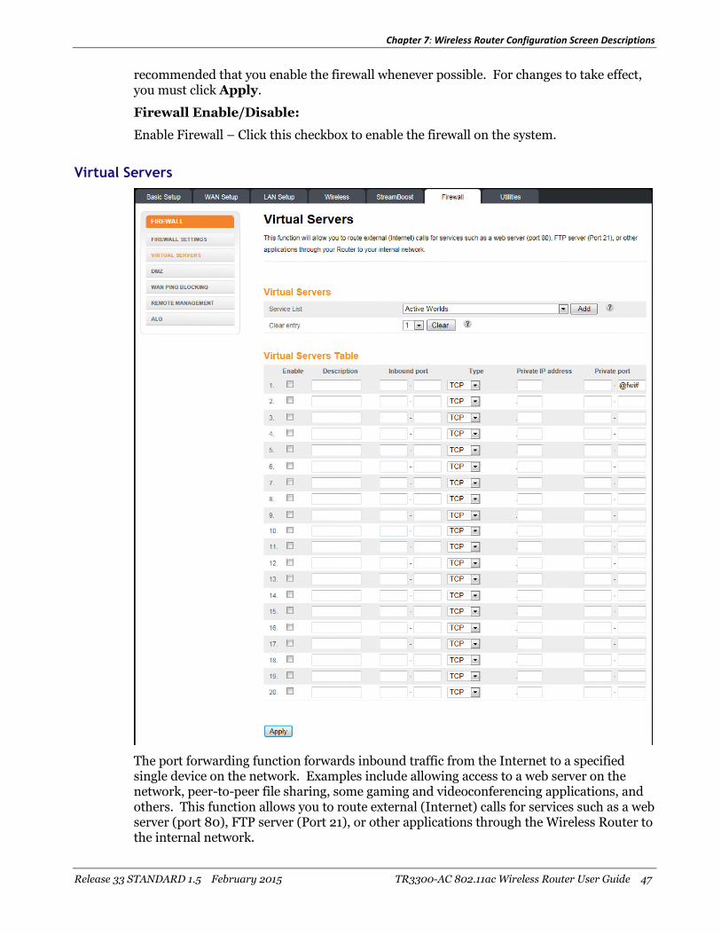
Chapter 7: Wireless Router Configuration Screen Descriptions
Release 33 STANDARD 1.5 February 2015 TR3300-AC 802.11ac Wireless Router User Guide 47
recommended that you enable the firewall whenever possible. For changes to take effect,you must click Apply.
Firewall Enable/Disable:
Enable Firewall – Click this checkbox to enable the firewall on the system.
Virtual Servers
The port forwarding function forwards inbound traffic from the Internet to a specifiedsingle device on the network. Examples include allowing access to a web server on thenetwork, peer-to-peer file sharing, some gaming and videoconferencing applications, andothers. This function allows you to route external (Internet) calls for services such as a webserver (port 80), FTP server (Port 21), or other applications through the Wireless Router tothe internal network.

Chapter 7: Wireless Router Configuration Screen Descriptions
Release 33 STANDARD 1.5 February 2015 TR3300-AC 802.11ac Wireless Router User Guide 48
Click Add to add a virtual server. Select a virtual server from the list and click Delete todelete a virtual server.
Virtual Servers:
Service List – Select the kind of service you would like to set up, and click Add.
Clear Entry – To clear an entry from the Virtual Servers Table, select the entry that youwant to clear and click Clear.
Virtual Servers Table:
Description – Enter a name for the virtual server.
Inbound Port – Enter the inbound port range for the virtual server. It should be the samerange as the local port.
Type – Sets the format for the port. Options are TCP, UDP, or BOTH.
Private IP Address – Enter the IP address of the machine on the LAN that you wantthe connections to go to.
Private Port – Enter the private port range for the virtual server. It should be the samerange as the inbound port.
DMZ
The DMZ feature allows you to specify one computer on the network to be placed outsideof the NAT firewall. This may be necessary if the NAT feature is causing problems with anapplication such as a game or video conferencing application.
Use this feature only on a temporary basis. The computer in the DMZ is not protectedfrom hacker attacks.
To put a computer in the DMZ, click the Enable DMZ checkbox, enter its IP address, andclick Apply.
IP Address Of Virtual DMZ Host:
Enable DMZ – Click this checkbox to enable DMZ on the network.
Static IP – Displays the Static IP address.
Private IP – Enter the IP address of the computer to be placed in the DMZ. Be sure thatthe address is not in the range of addresses delivered by the DHCP server if enabled. After

Chapter 7: Wireless Router Configuration Screen Descriptions
Release 33 STANDARD 1.5 February 2015 TR3300-AC 802.11ac Wireless Router User Guide 49
placing the computer in the DMZ, all ports on the computer are open to the Internet andnot protected.
WAN Ping Blocking
You can configure the Wireless Router not to respond to an ICMP Ping (ping to the WANport). This offers a heightened level of security.
Block ICMP Ping:
Block ICMP Ping Enable – Click this checkbox to enable WAN Ping Blocking.
Remote Management
Remote management lets you make changes to the Wireless Router's settings fromanywhere on the Internet. Before you enable this function, make sure you have set theadministrator password.
Remote Management Settings:
Remote Management Enable – Click this checkbox to enable the Remote Managementfeature.
Remote IP Settings – Select Any to allow management connections from any IP address, orselect IP Range to specify a range of IP addresses that can connect.

Chapter 7: Wireless Router Configuration Screen Descriptions
Release 33 STANDARD 1.5 February 2015 TR3300-AC 802.11ac Wireless Router User Guide 50
Remote IP Address From/To – Use these fields to enter the IP addresses that can connectto make changes to the settings. You must set Remote IP Settings to IP Range toactivate these fields.
Remote Access Port – Enter the port that you would like to use for remote access.
ALG
Application layer gateway settings allow the Wireless Router to recognize and treat certainnetwork protocols specially.
Application Layer Gateway:
Click the checkbox for each network protocol for which you want special handling.

Chapter 7: Wireless Router Configuration Screen Descriptions
Release 33 STANDARD 1.5 February 2015 TR3300-AC 802.11ac Wireless Router User Guide 51
Utilities
System Information
This page shows a summary of the system’s status.
Hardware Software Version:
Serial Number – This field displays the product serial number.
Bootcode Version – This field displays the bootcode version.
Hardware Version – This field displays the hardware version.
Firmware Version – This field displays the firmware version.

Chapter 7: Wireless Router Configuration Screen Descriptions
Release 33 STANDARD 1.5 February 2015 TR3300-AC 802.11ac Wireless Router User Guide 52
WAN Status Summary:
WAN MAC Address – This field displays the WAN MAC address.
Connection Setup – This field displays the connection type: Dynamic or Static
IP Address – This field displays the WAN IP address.
Subnet Mask – This field displays the WAN subnet mask.
Primary DNS – This field displays the Primary DNS IP address.
Secondary DNS – This field displays the Secondary DNS IP address.
Gateway – This field displays the gateway IP address.
LAN Status Summary:
MAC Address – This field displays the LAN MAC Address.
IP Address – This field displays the IP Address of the LAN.
Subnet Mask – This field displays the subnet mask of the LAN.
DHCP Server – This field displays the status of the DHCP Server: Enabled or Disabled.
Other Features Summary:
Firewall Settings - This field displays the status of the firewall settings: Enabled orDisabled.
SSID – This field displays the status of the SSID Broadcast function: Enabled or Disabled.
Security – This field displays the status of the Security feature: Enabled or Disabled.
UPNP – This field displays the status of the UPnP feature: Enabled or Disabled.
Remote Management – This field displays the status of the Remote Management feature:Enabled or Disabled.
WPS – This field displays the status of the WPS function: Enabled or Disabled.
Guest Access – This field displays the status of the Guest Access function: Enabled orDisabled.
Guest SSID – This field displays the name of the guest network that you set up.
Guest Password (PSK) – This field displays the password for the guest network.
Restart Router
It may be necessary to restart (reboot) the Wireless Router if it begins working improperly.Restarting the Wireless Router will not delete any of the configuration settings.

Chapter 7: Wireless Router Configuration Screen Descriptions
Release 33 STANDARD 1.5 February 2015 TR3300-AC 802.11ac Wireless Router User Guide 53
To restart the Wireless Router, click Restart.
Note: A dialog box prompts you to confirm that you want to restart the Wireless Router.Click OK to restart now or click Cancel to restart later.
Factory Default
This screen lets you restore all of the Wireless Router’s configuration settings to the factorydefault setting.
Click Factory Defaults to restore the factory default configuration settings.
Note: A dialog box prompts you to confirm that you want to restore the factory defaultsettings. Click OK to restore now or click Cancel to restore later.
Firmware Upgrade
From time to time, ARRIS may release new versions of firmware for the Wireless Router toprovide improvements and fixes to problems that may have existed. Use the Browsebutton to locate the new firmware file on a local device, and click Update to start theupdate procedure.
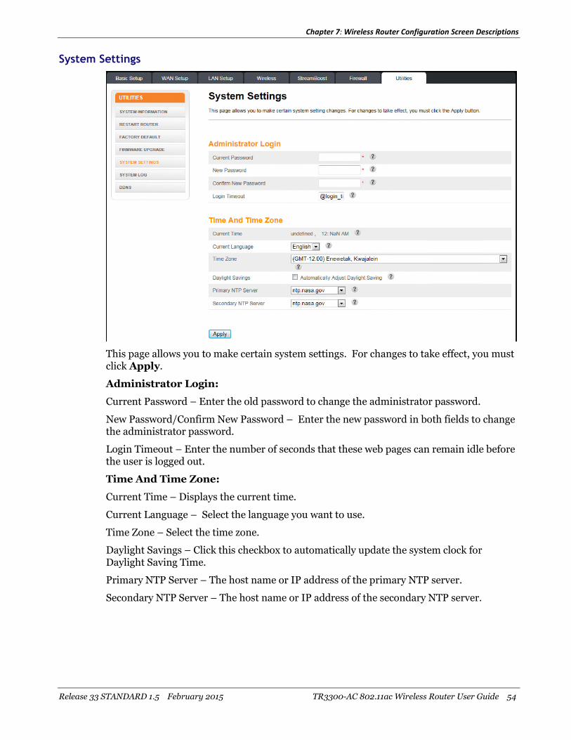
Chapter 7: Wireless Router Configuration Screen Descriptions
Release 33 STANDARD 1.5 February 2015 TR3300-AC 802.11ac Wireless Router User Guide 54
System Settings
This page allows you to make certain system settings. For changes to take effect, you mustclick Apply.
Administrator Login:
Current Password – Enter the old password to change the administrator password.
New Password/Confirm New Password – Enter the new password in both fields to changethe administrator password.
Login Timeout – Enter the number of seconds that these web pages can remain idle beforethe user is logged out.
Time And Time Zone:
Current Time – Displays the current time.
Current Language – Select the language you want to use.
Time Zone – Select the time zone.
Daylight Savings – Click this checkbox to automatically update the system clock forDaylight Saving Time.
Primary NTP Server – The host name or IP address of the primary NTP server.
Secondary NTP Server – The host name or IP address of the secondary NTP server.

Chapter 7: Wireless Router Configuration Screen Descriptions
Release 33 STANDARD 1.5 February 2015 TR3300-AC 802.11ac Wireless Router User Guide 55
System Log
This page displays the system logs. Click Refresh to update the list. Click Clear Log toclear the list.
DDNS
DDNS (Dynamic DNS) allows you to provide Internet users with a fixed domain name(instead of an IP address which may periodically change). This allows various locations onthe Internet to access the Wireless Router and the applications that are set up in thegateway's virtual servers without knowing your current IP address. For changes to takeeffect, you must click Apply.

Chapter 7: Wireless Router Configuration Screen Descriptions
Release 33 STANDARD 1.5 February 2015 TR3300-AC 802.11ac Wireless Router User Guide 56
Note: You must first create an account with a DDNS provider in order to use DDNS. TheDDNS provider maps the chosen domain name to your IP address.
DDNS Setting:
DDNS Enable – Click this checkbox to enable DDNS on the system.
DDNS Service – Sets the DDNS provider that the account uses. The options are DynDNSand TZO.
User Name – Enter the user name for the DDNS account.
Password – Enter the password for the DDNS account. (Provided by your DDNSprovider.)
Domain Name – Enter the domain name you selected to use with the DDNS account.

Release 33 STANDARD 1.5 February 2015 TR3300-AC 802.11ac Wireless Router User Guide 57
Chapter 8
Troubleshooting
The Wireless Router is plugged in, but the Power light is Off
Check all power connections. Is the power cord plugged in firmly at both ends?
If you plugged the power cord into a power strip, make sure the strip is switched on.
Avoid using an outlet controlled by a wall switch, if possible.
Finally, check the fuse or circuit breaker panel.
I'm not getting on the Internet (all connections)
It may take several minutes to establish a connection the first time you power up theWireless Router, especially when many people are online. Always leave the WirelessRouter plugged into AC power and connected to the modem.
Check the front panel lights:
The Power and WAN lights should be on.
If the Power light blinks for more than 30 minutes, call your service provider forassistance.
Check the cable connections. Connectors should be tight. Cables should not be pinched,kinked, or bent sharply—any of these can cause a break or short in the cable (you may haveto replace the cable).
Proceed to the Ethernet or wireless solutions if necessary.
I'm not getting on the Internet (Ethernet)
If you are using a switch, is the switch turned on?
Are you using the right type of Ethernet cable? Use an RJ45 Cat5e cable for directconnection to a computer; use a cross-over cable for connection to a switch.
Press the Reset button on the back of the Wireless Router.
A misconfiguration could lock out all access to the Wireless Router. If you think this hashappened, see Resetting the Wireless Router to Factory Defaults.
I'm not getting on the Internet (Wireless)
Check the indicator lights, see Using the Wireless Router — the Wi-Fi light should be on.
Does the connection utility discover your wireless LAN? If you turned off “Broadcast SSID”you need to manually enter the name of the wireless LAN in the connection utility.

Chapter 8: Troubleshooting
Release 33 STANDARD 1.5 February 2015 TR3300-AC 802.11ac Wireless Router User Guide 58
Change the security mode to “disabled”. Enable one of the other security modes as soon asyou find the problem.
A misconfiguration could lock out all access to the Wireless Router. If you think this hashappened, see Resetting the Wireless Router to Factory Defaults.
My wireless Internet connection stops working sometimes
This is usually caused by interference. Two common sources are 2.4GHz “remote”telephones and microwave ovens. If you cannot remove the interfering product, try using adifferent channel.
I can get on the Internet, but everything is slow
If the Web site you are visiting is very popular, that site may be having trouble servicing allthe requests. If other sites download quickly, wait for a few minutes and try again. Usageduring peak hours may also affect the connection speed.
Other communications on the LAN, or interference with wireless connections, may slowdown the connection.

Release 33 STANDARD 1.5 February 2015 TR3300-AC 802.11ac Wireless Router User Guide 59
Chapter 9
ARRIS Contacts
ARRIS offers broadband service providers a complete, integrated, application-oriented IPsuite of back-office automation tools for network content, subscriber, and workforcemanagement as well as advanced advertising and on demand services.
Before You Call ARRIS Support
When working with Technical Support, you can help us to expedite your call by followingthese guidelines:
Please be prepared to give your Technical Support Contract ID number whenever youcontact ARRIS Technical Support. If you do not know your Technical Support ContractID number or have questions about a support contract, please contact ARRIS TechnicalServices at [email protected] or (678) 473-8302.
Be prepared to provide your name, company name, site location, serial number of thesystem you are calling about (if applicable), system and software version numbers, andas much detail about the problem as possible.
Review available documentation, including release notes, product and installationmanuals, and online help for information about your problem.
Do not reboot or restart equipment or software processes prior to consulting withARRIS Technical Support—vital data that could assist in resolving the problem can belost when these actions are performed.
All personnel who call Technical Support should have a high level of familiarity withthe ARRIS system, including knowing the system passwords. We strongly recommendthat you have personnel trained through ARRIS Educational Services programs.
ARRIS Technical Support supports ARRIS-supplied products only. Issues related to otherhardware, software, or non-ARRIS networks must be addressed by your organization orthe appropriate third-party vendor.
By Telephone
North America Region
Legacy ARRIS +1 888 221 9797 (North America)
+1 678 473 5656 (Worldwide)
Legacy Motorola Home + 1 888 944 4357 (North America)
+1 215 323 2345 (Worldwide)

Chapter 9: ARRIS Contacts
Release 33 STANDARD 1.5 February 2015 TR3300-AC 802.11ac Wireless Router User Guide 60
Latin America Region:
Argentina: Legacy Motorola Home 0 800 666 3601
Aruba: Legacy Motorola Home 215 323 2346
Bolivia: Legacy Motorola Home 800 100 694
Brazil: Legacy Motorola Home 0 800 891 5314
Legacy ARRIS +55 11 2737 7629
Chile: Legacy Motorola Home 1230 020 5564
Legacy ARRIS +56 2 678 4500
Colombia: Legacy Motorola Home 1 8005 1 80947
Legacy ARRIS +57 1 381 9103
Costa Rica: Legacy Motorola Home 215 323 2346
Ecuador: Legacy Motorola Home 215 323 2346
El Salvador: Legacy Motorola Home 800 6625
Honduras: Legacy Motorola Home 800 0123, then 866 842 0264
Mexico: Legacy Motorola Home 001 866 391 2349
Legacy ARRIS 01 800 522 7747 or +52 55 22828531
Panama: Legacy Motorola Home 001 800 203 4345
Peru: Legacy Motorola Home 0 800 5 3651
Puerto Rico: Legacy Motorola Home 866 862 2627
Rep. Dominicana: Legacy Motorola Home 1 888 751 8898
Venezuela: Legacy Motorola Home 0 800 100 9161
Europe Region:
Europe: Legacy ARRIS +31 20 311 2525
Belgium: Legacy Motorola Home 0 800 72 163
Denmark: Legacy Motorola Home 80 88 6748
Finland: Legacy Motorola Home 0 800 114 263
France: Legacy Motorola Home 0 800 90 7038
Germany: Legacy Motorola Home 0 800 18 73019
Hungary: Legacy Motorola Home 06 800 18164
Ireland: Legacy Motorola Home 1 800 55 9871
Israel Golden Lines: Legacy Motorola Home 1 809 25 2071
Israel Bezeq: Legacy Motorola Home 1 809 42 9181
Israel Barak: Legacy Motorola Home 1 809 31 5435
Italy: Legacy Motorola Home 800 788 304
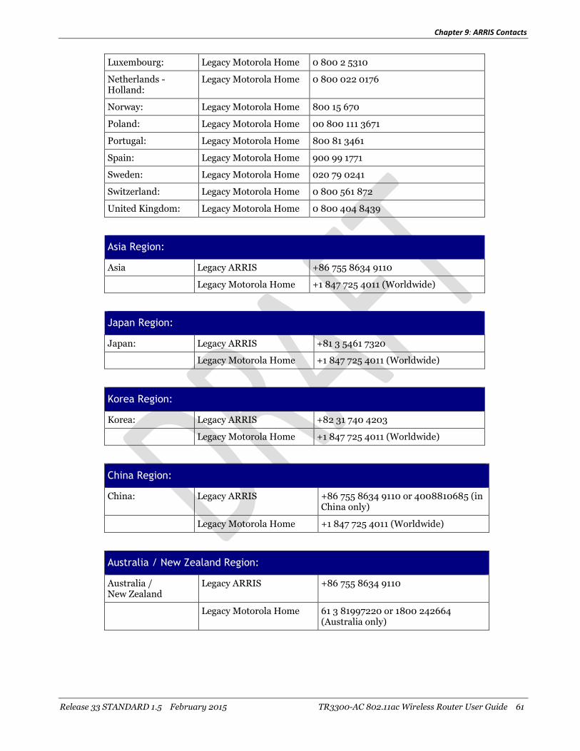
Chapter 9: ARRIS Contacts
Release 33 STANDARD 1.5 February 2015 TR3300-AC 802.11ac Wireless Router User Guide 61
Luxembourg: Legacy Motorola Home 0 800 2 5310
Netherlands -Holland:
Legacy Motorola Home 0 800 022 0176
Norway: Legacy Motorola Home 800 15 670
Poland: Legacy Motorola Home 00 800 111 3671
Portugal: Legacy Motorola Home 800 81 3461
Spain: Legacy Motorola Home 900 99 1771
Sweden: Legacy Motorola Home 020 79 0241
Switzerland: Legacy Motorola Home 0 800 561 872
United Kingdom: Legacy Motorola Home 0 800 404 8439
Asia Region:
Asia Legacy ARRIS +86 755 8634 9110
Legacy Motorola Home +1 847 725 4011 (Worldwide)
Japan Region:
Japan: Legacy ARRIS +81 3 5461 7320
Legacy Motorola Home +1 847 725 4011 (Worldwide)
Korea Region:
Korea: Legacy ARRIS +82 31 740 4203
Legacy Motorola Home +1 847 725 4011 (Worldwide)
China Region:
China: Legacy ARRIS +86 755 8634 9110 or 4008810685 (inChina only)
Legacy Motorola Home +1 847 725 4011 (Worldwide)
Australia / New Zealand Region:
Australia /New Zealand
Legacy ARRIS +86 755 8634 9110
Legacy Motorola Home 61 3 81997220 or 1800 242664(Australia only)

Chapter 9: ARRIS Contacts
Release 33 STANDARD 1.5 February 2015 TR3300-AC 802.11ac Wireless Router User Guide 62
By Email
North America:
Headend and Network Equipment:
RF Optics: Ruckus, Optics, Amps, Nodes,Transmitters, CHP, Passives,OptiMax, CoreWave, CoreView
CMTS Products: C3, C4, ICO, ASA, CxM, CMTS1000,CMTS1500, E6000
CMTS Product: BSR, SRM4, HSIM4, TX32, RX48,SRM10G
Moxi and WHSProducts:
Moxi, MCR, Portal, WHS, WHS5225,MediaPlayer, Whole Home Solution,Gateway
D5 and DVSProducts:
D5, Application Manager, VIPr,Hemi, Encore, Quartet, Prelude, EGTor DVS
DVS Products: CAS, DACs, CASMR, APEX3000,NC2000, DreamGallery, SecureMedia, VideoFlow, AVP100, STBs,AS-RAC, QT Plus, CherryPicker,Encoder, Astria
EMP Products: AdEdge, APS, BEQ6XXX, BME50,BMR1200, CVEx, MSP2XXX, RMS,SBSS, SVA, VMS
Digital Ad Insertion: Ad Insertion, Skyvision, Spots, ACM,n5, XMS
Video on Demand: Video OnDemand, VOD, nABLE,CMM, n5, XMS, Transit
VOD Products: B1 Video Server, M3 Video Server,cDVR Video Solution
WorkAssure: WorkAssure, I&R, SageQuest,Wireless Matrix, Tech Director, TechCalendar, SSM Alarms
Assurance Products: ServAssure, OpsLogic, Powersense,SALIVE, EventAssure, HouseCheck,Data Warehouse, Starnodes
GPON Product: GPON, POL, Carrier Ethernet [email protected]
Satellite andModular Systems:
DSR, Uplink, IPTV, Encoder [email protected]
Korea: Legacy ARRIS Products [email protected]
Korea: Legacy Motorola Home [email protected]
Australia / NewZealand:
Legacy ARRIS Products [email protected]

Chapter 9: ARRIS Contacts
Release 33 STANDARD 1.5 February 2015 TR3300-AC 802.11ac Wireless Router User Guide 63
Australia / NewZealand:
Legacy Motorola Home [email protected]
Customer Premise Equipment:
Touchstone Products: TGxxx, TMxxx, Touchstone, TTM,Packet Ace, Cornerstone, HDT,Incognito, CableModem, eMTA,Telephone Gateway
CableModem: Cable Modem, MTA [email protected]
International (All Products):
Latin America: Legacy ARRIS Products [email protected]
Latin America: Legacy Motorola Home [email protected]
Europe: Legacy ARRIS Products [email protected]
Europe: Legacy Motorola Home [email protected]
Asia: Legacy ARRIS Products [email protected]
Asia: Legacy Motorola Home [email protected]
Japan: Legacy ARRIS Products [email protected]
Japan: Legacy Motorola Home [email protected]
Ask ARRIS Customer Portal
The Ask ARRIS Customer Portal enables you to:
Use innovative search technology to deliver fast, relevant, reliable information exactlywhen you need it, 24x7
Manage technical support cases for your products, support level, and site location
Access technical documentation and webcasts
To use the portal, you will need to register for the site using your support contract ID andemail address. To access the customer portal:
http://www.arris.com/support
Global Knowledge Services and Training
For more information about Global Knowledge Services and the programs we offer, e-mailus at:

TR3300-AC 802.11ac Wireless Router User Guide
Corporate Headquarters
ARRIS · Suwanee · Georgia · 30024 · USA
T: 1-678-473-2000 F: 1-678-473-8470
www.arris.com

This file was downloaded from the sitemans.io
Instruction manuals and user guides
SamsungPioneerAlpineLGDellSharpSonyPhilipsEpsonNetgear