towable generators and light towertowable generators and light tower (diesel liquid cooled) tg8lt...
TRANSCRIPT

Towable Generators and
Light Tower
(Diesel Liquid Cooled)
TG8LT
TG10T, 15T, 20T and 25T
Installation & Operating Manual
8/12 MN2423

Any trademarks used in this manual are the property of their respective owners.
WARNING:CALIFORNIA PROPOSITION 65 WARNING:
Engine exhaust from this product contains chemicals knownto the state of California to cause cancer, birth defects andother reproductive harm.
WARNING:CALIFORNIA PROPOSITION 65 WARNING:
Battery posts, terminals and related accessories are known tothe state of California to cause cancer, birth defects and otherreproductive harm.

Table of Contents
Table of Contents iMN2423
Section 1Product Safety Information 1-1. . . . . . . . . . . . . . . . . . . . . . . . . . . . . . . . . . . . . . . . . . . . . . . . . . . . . . . . . . . . . . . . . . . . . . . .
Safety Notice 1-1. . . . . . . . . . . . . . . . . . . . . . . . . . . . . . . . . . . . . . . . . . . . . . . . . . . . . . . . . . . . . . . . . . . . . . . . . . . . . . . . . .Responsibility 1-1. . . . . . . . . . . . . . . . . . . . . . . . . . . . . . . . . . . . . . . . . . . . . . . . . . . . . . . . . . . . . . . . . . . . . . . . . . . . . . . . .IMPORTANT SAFETY INSTRUCTIONS 1-2. . . . . . . . . . . . . . . . . . . . . . . . . . . . . . . . . . . . . . . . . . . . . . . . . . . . . . . . . .Caution Statements 1-6. . . . . . . . . . . . . . . . . . . . . . . . . . . . . . . . . . . . . . . . . . . . . . . . . . . . . . . . . . . . . . . . . . . . . . . . . . . .
Section 2General Information 2-1. . . . . . . . . . . . . . . . . . . . . . . . . . . . . . . . . . . . . . . . . . . . . . . . . . . . . . . . . . . . . . . . . . . . . . . . . . . . . . .
Limited Warranty 2-1. . . . . . . . . . . . . . . . . . . . . . . . . . . . . . . . . . . . . . . . . . . . . . . . . . . . . . . . . . . . . . . . . . . . . . . . . . . . . . .Section 3Receiving & Installation 3-1. . . . . . . . . . . . . . . . . . . . . . . . . . . . . . . . . . . . . . . . . . . . . . . . . . . . . . . . . . . . . . . . . . . . . . . . . . .
Receiving & Inspection 3-1. . . . . . . . . . . . . . . . . . . . . . . . . . . . . . . . . . . . . . . . . . . . . . . . . . . . . . . . . . . . . . . . . . . . . . . . .Lifting the Equipment 3-1. . . . . . . . . . . . . . . . . . . . . . . . . . . . . . . . . . . . . . . . . . . . . . . . . . . . . . . . . . . . . . . . . . . . . . . . . . .Light Tower Installation 3-1. . . . . . . . . . . . . . . . . . . . . . . . . . . . . . . . . . . . . . . . . . . . . . . . . . . . . . . . . . . . . . . . . . . . . . . . .Light Tower Checks 3-2. . . . . . . . . . . . . . . . . . . . . . . . . . . . . . . . . . . . . . . . . . . . . . . . . . . . . . . . . . . . . . . . . . . . . . . . . . . .
Trailer Stabilization Checks 3-2. . . . . . . . . . . . . . . . . . . . . . . . . . . . . . . . . . . . . . . . . . . . . . . . . . . . . . . . . . . . . . . . .Light Mast Checks 3-2. . . . . . . . . . . . . . . . . . . . . . . . . . . . . . . . . . . . . . . . . . . . . . . . . . . . . . . . . . . . . . . . . . . . . . . . .Light Fixtures Checks 3-2. . . . . . . . . . . . . . . . . . . . . . . . . . . . . . . . . . . . . . . . . . . . . . . . . . . . . . . . . . . . . . . . . . . . . .Electrical Systems Checks 3-2. . . . . . . . . . . . . . . . . . . . . . . . . . . . . . . . . . . . . . . . . . . . . . . . . . . . . . . . . . . . . . . . . .
Generator Installation 3-2. . . . . . . . . . . . . . . . . . . . . . . . . . . . . . . . . . . . . . . . . . . . . . . . . . . . . . . . . . . . . . . . . . . . . . . . . . .Equipment Checks 3-3. . . . . . . . . . . . . . . . . . . . . . . . . . . . . . . . . . . . . . . . . . . . . . . . . . . . . . . . . . . . . . . . . . . . . . . . . . . . .
Trailer Checks 3-3. . . . . . . . . . . . . . . . . . . . . . . . . . . . . . . . . . . . . . . . . . . . . . . . . . . . . . . . . . . . . . . . . . . . . . . . . . . . .Engine/Generator Checks 3-3. . . . . . . . . . . . . . . . . . . . . . . . . . . . . . . . . . . . . . . . . . . . . . . . . . . . . . . . . . . . . . . . . .Electrical Connections 3-3. . . . . . . . . . . . . . . . . . . . . . . . . . . . . . . . . . . . . . . . . . . . . . . . . . . . . . . . . . . . . . . . . . . . . .
Battery Connections 3-5. . . . . . . . . . . . . . . . . . . . . . . . . . . . . . . . . . . . . . . . . . . . . . . . . . . . . . . . . . . . . . . . . . . . . . . . . . . .Section 4Operation 4-1. . . . . . . . . . . . . . . . . . . . . . . . . . . . . . . . . . . . . . . . . . . . . . . . . . . . . . . . . . . . . . . . . . . . . . . . . . . . . . . . . . . . . . . . .
Towing the Equipment 4-1. . . . . . . . . . . . . . . . . . . . . . . . . . . . . . . . . . . . . . . . . . . . . . . . . . . . . . . . . . . . . . . . . . . . . . . . . .Light Tower Towing Instructions 4-1. . . . . . . . . . . . . . . . . . . . . . . . . . . . . . . . . . . . . . . . . . . . . . . . . . . . . . . . . . . . . . . . . .Light Tower Setup 4-2. . . . . . . . . . . . . . . . . . . . . . . . . . . . . . . . . . . . . . . . . . . . . . . . . . . . . . . . . . . . . . . . . . . . . . . . . . . . . .Light Tower Stow Procedure 4-2. . . . . . . . . . . . . . . . . . . . . . . . . . . . . . . . . . . . . . . . . . . . . . . . . . . . . . . . . . . . . . . . . . . . .Light Tower Setup for Towing 4-3. . . . . . . . . . . . . . . . . . . . . . . . . . . . . . . . . . . . . . . . . . . . . . . . . . . . . . . . . . . . . . . . . . . .Generator Towing Instructions 4-3. . . . . . . . . . . . . . . . . . . . . . . . . . . . . . . . . . . . . . . . . . . . . . . . . . . . . . . . . . . . . . . . . . .Trailer Setup 4-3. . . . . . . . . . . . . . . . . . . . . . . . . . . . . . . . . . . . . . . . . . . . . . . . . . . . . . . . . . . . . . . . . . . . . . . . . . . . . . . . . .Lug Nut Tightness 4-4. . . . . . . . . . . . . . . . . . . . . . . . . . . . . . . . . . . . . . . . . . . . . . . . . . . . . . . . . . . . . . . . . . . . . . . . . . . . .Voltage Selection 4-4. . . . . . . . . . . . . . . . . . . . . . . . . . . . . . . . . . . . . . . . . . . . . . . . . . . . . . . . . . . . . . . . . . . . . . . . . . . . . .Pre−Start Procedure 4-6. . . . . . . . . . . . . . . . . . . . . . . . . . . . . . . . . . . . . . . . . . . . . . . . . . . . . . . . . . . . . . . . . . . . . . . . . . .Operating Procedures 4-6. . . . . . . . . . . . . . . . . . . . . . . . . . . . . . . . . . . . . . . . . . . . . . . . . . . . . . . . . . . . . . . . . . . . . . . . . .Digital Engine Controller Description 4-8. . . . . . . . . . . . . . . . . . . . . . . . . . . . . . . . . . . . . . . . . . . . . . . . . . . . . . . . . . . . . .Inputs and Outputs 4-9. . . . . . . . . . . . . . . . . . . . . . . . . . . . . . . . . . . . . . . . . . . . . . . . . . . . . . . . . . . . . . . . . . . . . . . . . . . . .Set points 4-10. . . . . . . . . . . . . . . . . . . . . . . . . . . . . . . . . . . . . . . . . . . . . . . . . . . . . . . . . . . . . . . . . . . . . . . . . . . . . . . . . . . . .
Section 5Troubleshooting and Maintenance 5-1. . . . . . . . . . . . . . . . . . . . . . . . . . . . . . . . . . . . . . . . . . . . . . . . . . . . . . . . . . . . . . . . .
Maintenance 5-1. . . . . . . . . . . . . . . . . . . . . . . . . . . . . . . . . . . . . . . . . . . . . . . . . . . . . . . . . . . . . . . . . . . . . . . . . . . . . . . . . .Flood Light Bulb Replacement 5-1. . . . . . . . . . . . . . . . . . . . . . . . . . . . . . . . . . . . . . . . . . . . . . . . . . . . . . . . . . . . . . . . . . .Cleaning 5-2. . . . . . . . . . . . . . . . . . . . . . . . . . . . . . . . . . . . . . . . . . . . . . . . . . . . . . . . . . . . . . . . . . . . . . . . . . . . . . . . . . . . . .Equipment Troubleshooting Guide 5-3. . . . . . . . . . . . . . . . . . . . . . . . . . . . . . . . . . . . . . . . . . . . . . . . . . . . . . . . . . . . . . .
Appendix AWiring Diagrams A-1. . . . . . . . . . . . . . . . . . . . . . . . . . . . . . . . . . . . . . . . . . . . . . . . . . . . . . . . . . . . . . . . . . . . . . . . . . . . . . . . . .

ii Table of Contents MN2423

Section 1Product Safety Information
Product Safety Information 1-1MN2423
Safety Notice Be sure that you are completely familiar with the safe operation of this equipment. Thisequipment may be connected to other machines that have rotating parts or parts that arecontrolled by this equipment. Improper use can cause serious or fatal injury. Alwaysdisconnect all electrical loads before starting the equipment.Installation and repair procedures require specialized skills with electrical generating equipmentand liquid cooled engine systems. Any person that installs or repairs this equipment must havethese specialized skills to ensure that this generating unit is safe to operate. Seek expert advisefor repairs or any questions you may have about the safe installation and operation.The precaution statements are general guidelines for the safe use and operation of thisequipment. It is not practical to list all unsafe conditions. Therefore, if you use a procedure thatis not recommended in this manual you must determine if it is safe for the operator and allpersonnel in the proximity to the equipment and connected loads. If there is any question of thesafety of a procedure please seek expert advise before starting or stopping the equipment.This equipment contains high voltages. Electrical shock can cause serious or fatal injury. Onlyqualified personnel should attempt the start−up procedure or troubleshoot this equipment.This equipment may be connected to other machines that have rotating parts or parts that aredriven by this equipment. Improper use can cause serious or fatal injury. Only qualifiedpersonnel should attempt the start−up procedure or troubleshoot this equipment.
− System documentation must be available to anyone that operates this equipment at alltimes.
− Keep non-qualified personnel at a safe distance from this equipment.− Only qualified personnel familiar with the safe installation, operation and maintenance
of this device should attempt start-up or operating procedures.− Always stop engine before making or removing any connections.− Always stop engine and allow it to cool before refueling.
Responsibility When your equipment is delivered, it becomes the responsibility of the owner/operator to preventunsafe conditions and operation of the equipment. Some responsibilities include (but are notlimited to) the following:
1. It is the responsibility of the owner/operator to ensure that this equipment is correctlyand safely installed.
2. It is the responsibility of the owner/operator to ensure that this equipment, wheninstalled fully complies with all federal, state and local codes.
3. It is the responsibility of the owner/operator to ensure that any person operating thisequipment has been properly trained.
4. It is the responsibility of the owner/operator to ensure that any person operating thisequipment has access to all manuals and information required for the safe use andoperation of this equipment.
5. It is the responsibility of the owner/operator to ensure that it is properly maintained andsafety inspected at regular scheduled intervals.
6. It is the responsibility of the owner/operator to ensure that any person who has notbeen trained on the safe use of this equipment does not have access to thisequipment.
Read This Manual ThoroughlyIf you do not understand any concept, any procedure, any safety warning statement, any safetycaution statement or any portion of this manual, seek expert advise. Make sure you understandthe information in this manual so that you can safely enjoy the full use of this equipment.
This symbol is shown throughout the manual to indicate a connection to ground reference point.
Symbols
Indicates a potentially hazardous situation which, if not avoided, could result in injury or death.
Indicates a potentially hazardous situation which, if not avoided, could result in injury or death.

1-2 Product Safety Information MN2423
Precaution Statements Used In This ManualThere are three classifications of precautionary statements used in this manual. The most criticalis a WARNING statement, then the Caution statement and the least critical is the Notestatement. The usage of each statement is as follows:
WARNING: Indicates a potentially hazardous situation which, if not avoided, could result in injury ordeath.
Caution: Indicates a potentially hazardous situation which, if not avoided, could result in damage toproperty.
Note: Additional information that is not critical to the installation or operation.
IMPORTANT SAFETY INSTRUCTIONSSAVE THESE INSTRUCTIONS − This manual contains important instructions for the equipment thatshould be followed during installation, operation and maintenance of this equipment.For ease of reading, the Warning statements are divided into four categories: Operation, Burn, Installation,and Maintenance.
Operation StatementsWARNING: If the trailer is not properly secured to the tow vehicles tow hitch, the trailer may separate
from the tow vehicle and cause severe injury or property damage. Always ensure that the towhitch and trailer tongue are properly connected, in good working condition and that safetychains are properly connected from the trailer to the tow vehicle.
WARNING: Never allow a person to ride in or on a trailer that is being towed. All states prohibitpassengers in towed vehicles. A person can fall off and be struck by another vehicle or runover by the towed trailer. Failure to observe this warning can result in death.
WARNING: Before using a tow vehicle, verify that the vehicle is designed for the load. Using a vehiclethat is too small is very dangerous. Be certain that it can handle the M.G.V.W. (MaximumGross Vehicle Weight) and the tongue weight for safe towing and braking.
WARNING: For a new trailer, the wheel lug nuts should be tightened to the proper torque specificationbefore use, after 50 miles of operation and every 100 miles of operation thereafter. Failure tocheck the lug nuts for proper tightness can result in an accident due to a wheel falling fromthe trailer.
WARNING: Never operate a trailer or tow vehicle that has a loose, missing or broken lug nut. The traileris designed for safe operation with all lug nuts installed and all at the proper torque rating.Operating the trailer with one or more broken or missing lug nuts greatly increases the loadon the remaining nuts and can cause failure of the remaining nuts that can result in anaccident due to a wheel falling from the trailer.
WARNING: Never operate this equipment in a manner other than as described in this manual. Operationin any manner not described in this manual should be considered unsafe and should not beattempted. Never start the engine unless you have first verified that the installation andoperation of the equipment are as described in this manual.
WARNING: Be sure that you are completely familiar with the safe operation of this equipment. Thisequipment may be connected to other machines that have rotating parts or parts that arecontrolled by this equipment. Improper use can cause serious or fatal injury.
WARNING: Exhaust fumes/gases are extremely dangerous and can cause severe illness or death. Neverbreath exhaust fumes produced by a running engine. Only run the engine outdoors whereventilation is plentiful. Exhaust gases contain carbon monoxide, a colorless, odorless andextremely dangerous gas that can cause unconsciousness or death. Symptoms of carbonmonoxide poisoning include: dizziness, nausea, headaches, sleepiness, vomiting orincoherence. If you or anyone else experiences these symptoms, get out into fresh airimmediately. Stop the engine and do not restart the engine until it has been inspected and ifnecessary repaired or reinstalled in a well ventilated area.
WARNING: When operating this equipment remain alert at all times. Never operate machinery whenphysically or mentally fatigued, or while under the influence of alcohol, drugs or medication.
Continued on next page.

Product Safety Information 1-3MN2423
Operation Statements ContinuedWARNING: Gasoline and diesel fuel are flammable and can cause fire, explosions, injury or death. For
storage or refueling handle fuel with care and only in clean, approved, properly marked safetyfuel containers.
WARNING: Do not overfill the fuel tank. Only fill the tank to within 1/2� of the top of the tank to allowspace for fuel expansion. Overfilling of tank may cause fuel to spill out onto engine andcause fire or explosion.
WARNING: Clean up fuel spills by wiping completely dry before starting engine. Gasoline and diesel fuelare flammable and can cause fire, explosions, injury or death.
WARNING: Make sure the fuel cap is completely and securely closed after refueling to prevent spillage.Gasoline and diesel fuel are flammable and can cause fire, explosions, injury or death.
WARNING: Over crank indication can mean a loss of crank disconnect signal during the previous runperiod. Attempting to restart the engine with no crank disconnect signal can destroy thestarter motor, which can cause serious personal injury.
WARNING: Hot exhaust gasses must never be directed toward anything that may catch fire or explode.WARNING: Never operate this equipment indoors or in a poorly ventilated area such as a tunnel or cave.
Exhaust fumes are extremely dangerous to all personnel that are in or in contact with that area.WARNING: Keep equipment at least three feet away from buildings and other structures.WARNING: Keep equipment away from flammable or hazardous materials (trash, rags, lubricants,
explosives, paints etc.) and grass or leaf build up.WARNING: Some parts of this equipment rotate during operation. Rotating parts can present extreme
danger if clothing or body extremities are caught by the rotating part and can cause seriousor fatal injury. Never touch a part of the equipment until the engine has been stopped and allrotating parts are completely stopped. Also, disconnect the battery terminals to preventaccidental engine rotation during servicing.
WARNING: Never move equipment set that is running. Loads should be connected and position securebefore starting the engine. Hazards are caused by moving equipment that is running.
WARNING: Never connect or disconnect loads during operation. Always connect load circuits beforestarting the engine and use external branch disconnects etc. to switch loads On/Off.
WARNING: High voltage is present whenever engine is running. Electrical shock can cause serious orfatal injury. Never operate electrical equipment while standing in water, on wet ground or withwet hands, feet or shoes or while barefoot.
WARNING: High voltage is present whenever the engine is running. Electrical shock can cause seriousor fatal injury. Always stop engine before connecting or disconnecting power cords orexternal devices.
WARNING: Be sure that you understand how to stop the engine quickly in case of an emergency situation.Become familiar with the controls and safety systems provided with this equipment.
WARNING: Always wear safety glasses with side shields and hearing protection when working near theequipment.
WARNING: Improper operation may cause violent motion of connected equipment. Be certain thatunexpected movement will not cause injury to personnel or damage to equipment.
WARNING: Never permit anyone to operate the equipment without proper instructions. Be sure to keep acopy of this manual with the equipment so that all users can be properly informed of its safeoperation.
WARNING: Never allow children or pets to be in the area where the equipment is running. The equipmentand the equipment being powered may cause injury or death.
WARNING: Never operate the equipment unless all guards, covers, shields and other safety items areproperly installed.
WARNING: Do not put hands, feet, tools clothing or other objects near rotating parts such as drive shaft,pulley, belt etc. Rotating parts cause extremely dangerous situations because they can catchloose clothing or extremities and cause serious or fatal injury.
WARNING: Never operate the engine when the air cleaner is removed. An engine backfire can causeserious burns.
Continued on next page.
1-4 Product Safety Information MN2423
Operation Statements ContinuedWARNING: Never “jump start” equipment to start the engine. If the battery charge is insufficient to start
the engine, charge or replace the battery and try to restart. Jump starting a battery can causethe battery to explode and cause severe injury or death to anyone in the area.
WARNING: Do not smoke near equipment during operation or when close to fuel source. Gasoline anddiesel fuel are flammable and can cause fire, explosions, injury or death.
WARNING: Keep a fire extinguisher near the equipment while in use. An extinguisher rated “ABC” by theNational Fire Protection Association is appropriate.
Operation Statements − Light TowerWARNING: Never stand under or close to an object that is being hoisted or lift into position. Accidents
happen and if the object falls or tips over you or someone else could be crushed by theweight of the object causing severe injury or death to yourself or others. Always remain asafe distance from the object and always wear protective head gear (hard hat).
WARNING: When erecting or stowing the mast assembly, be aware of the pinch points such as where thetower structures join or where the cable and winch are located. Careless operation can resultin injury. Keep extremities away from moving parts to avoid injury.
WARNING: Before erecting the mast assembly, be certain that the outriggers are properly set to stabilizethe light tower and that they are secure and are not damaged. Erecting the mast withoutsetting the outriggers can cause the light tower to tip over when raising the mast.
WARNING: Before erecting the mast assembly, be certain that there are no overhead wires. Contact withoverhead wiring presents an electrical shock hazard that may cause severe injury or death.
WARNING: Before erecting the mast assembly, be certain that there are no overhead obstructions thatthe mast will hit when raising it. Hitting an object (tree limb etc.) may damage the mast orcause the light tower to tip over and may result in injury or property damage.
WARNING: The mast assembly must remain in the stowed position until the outriggers are properly set tostabilize the trailer . Erecting the mast without setting the outriggers can cause the lighttower set to tip over when raising the mast.
WARNING: Never attempt to move the light tower when the mast is in the vertical position. All Outriggerand trailer jacks must remain in position and the trailer level until the mast is in its’ stowedposition. Failure to follow this warning may result in severe injury and property damage if thetrailer tips over.
WARNING: Never move or reposition a light tower when the mast is extended or in the vertical position.Unless the mast is in its stowed position, it may contact overhead wires or cause the lighttower to be unbalanced or tip over.
Burn StatementsWARNING: Parts of this equipment are extremely hot during and after operation. To prevent severe
burns, do not touch any part of the equipment until you have first determined if the part ishot. Wear protective clothing and after use allow sufficient time for parts to cool beforetouching any part of the equipment.
WARNING: Do not touch the hot exhaust parts. In addition to a severe burn, the sudden involuntary jerkof the hand or body part caused by contact with high voltage or a hot surface can result ininjury to yourself or others.
WARNING: Engine coolant is under pressure and is near the boiling point of water when engine is hot.Do not open the coolant system until the engine has completely cooled. Hot coolant cancause severe burns and other injuries. When engine is cool, coolant level can be checked.
Burn Statements − Light TowerWARNING: Light fixtures become extremely hot during use. To prevent severe burns, do not touch light
fixtures, bulbs or other components until they have cooled and no longer present a burn hazard.Wear protective clothing when placing the tower in the stowed position after use and do not allowany person to touch the light fixtures.
Installation StatementsWARNING: Disconnect the battery’s ground terminal before working in the vicinity of the battery or
battery wires. Contact with the battery can result in electrical shock when a tool accidentlytouches the positive battery terminal or wire. The risk of such shock is reduced when theground lead is removed during installation and maintenance.
Continued on next page.

Product Safety Information 1-5MN2423
Installation Statements ContinuedWARNING: Installation and repair procedures requires specialized skills with electrical generating
equipment and small engine systems. Any person that installs or performs repairs must havethese specialized skills to ensure that the equipment set is safe to operate. Seek expertadvise for installation or repairs.
WARNING: Be sure the system is properly grounded before applying power. Do not apply AC powerbefore you ensure that grounds are connected. Electrical shock can cause serious or fatalinjury. NEC requires that the frame and exposed conductive surfaces (metal parts) beconnected to an approved earth ground. Local codes may also require proper grounding ofequipment systems.
Warning: Do not connect the equipment output neutral to the frame or local ground. The equipmentoutput is isolated from ground. NEC and local codes require that the equipment outputremain isolated from local ground reference.
WARNING: Place protective covers over all rotating parts such as drive shaft, pulley, belt etc. Rotatingparts cause extremely dangerous situations because they can catch loose clothing orextremities and cause serious or fatal injury.
WARNING: Unauthorized modification of equipment may make the unit unsafe for operation or may impairthe operation of the unit. Never start equipment that has been modified or tampered with. Be surethat all covers and guards are properly installed and that the unit is safe before starting theengine. If you are unsure, seek expert advise before starting the engine.
WARNING: When moving this equipment, use reasonable caution. Be careful where you place fingersand toes to prevent injury “Pinch Points”. Never try to lift the equipment without a hoist or liftmeans because they are heavy and bodily injury may result.
Warning: Never connect this equipment to the electrical system of any building unless a licensedelectrician has installed an approved transfer switch. The national electrical code (NEC)requires that connection of a equipment to any electrical circuit normally powered by meansof an electric utility must be connected by means of approved transfer switch equipment toisolate the electrical circuit from the utility distribution system when the equipment isoperating. Failure to isolate the electrical circuits by such means may result in injury or deathto utility power workers due to backfeed of electrical energy onto the utility lines.
WARNING: Circuit overload protection must be provided in accordance with the National Electrical Codeand local regulations.
WARNING: Check Ground Fault Circuit Interrupt (GFCI) receptacles monthly by using the “Test” and“Reset” buttons.
WARNING: Have electrical circuits and wiring installed and checked by licensed electrician or qualifiedtechnician. Electrical shock can cause serious or fatal injury.
Maintenance StatementsWARNING: Installation and servicing of batteries is to be performed or supervised by personnel
knowledgeable of batteries and the required precautions. Keep unauthorized personnel awayfrom batteries.
WARNING: Before servicing the equipment, be sure to disconnect the battery terminals to preventaccidental engine rotation or starting.
WARNING: Before cleaning, inspecting, repairing or performing any maintenance to the equipment,always be sure the engine has stopped and that all rotating parts have also stopped. Afterstopping, certain components are still extremely hot so be careful not to get burned.
WARNING: Before servicing the equipment, be sure to disconnect the glow plugs or spark plug wires andthe battery terminals to prevent accidental engine rotation or starting.
WARNING: Engine coolant is under pressure and is near the boiling point of water when engine is hot.Do not open the coolant system until the engine has completely cooled. Hot coolant cancause severe burns and other injuries. When engine is cool, coolant level can be checked.
WARNING: Inspect all wiring frequently and replace any damaged, broken or frayed wiring or wires withdamaged insulation immediately. Electrical shock can cause serious or fatal injury.
WARNING: Disconnect all electrical wires and load devices from equipment power outlets beforeservicing the equipment. Electrical shock can cause serious or fatal injury. Always treatelectrical circuits as if they are energized.
Continued on next page.

1-6 Product Safety Information MN2423
Maintenance Statements ContinuedWARNING: A battery presents a risk of fire and explosion because they generate hydrogen gas.
Hydrogen gas is extremely explosive. Never jump start a battery, smoke in the area aroundthe battery or cause any spark to occur in the area around the battery.
WARNING: Do not mutilate the battery or dispose of a battery in a fire. The battery is capable ofexploding. If the battery explodes, electrolyte solution will be released in all directions.Battery electrolyte solution is caustic and can cause severe burns and blindness. Ifelectrolyte contacts skin or eyes, immediately flush the area with water and seek medicalattention quickly.
WARNING: The battery electrolyte is a dilute sulfuric acid that is harmful to the skin and eyes. It iselectrically conductive and corrosive. If electrolyte contacts the skin, flush the areaimmediately with water and wash it off using soap and water. If electrolyte contacts the eyes,immediately flush the eye thoroughly with water and seek medical attention quickly.
WARNING: A battery presents a risk of electrical shock hazard and high short circuit current. Electricalshock can cause serious or fatal injury. Never wear jewelry, watch or any metal objects whenin the area around the battery.
WARNING: Check fuel tank, fuel line, and connections monthly for fuel leaks. Diesel is flammable andcan cause fire, explosions, injury or death. If a leak is found, replace only with approved pipeor components.
Caution StatementsCaution: Avoid installing the equipment beside heat generating equipment, or directly below water or
steam pipes or in the vicinity of corrosive substances or vapors, metal particles and dust.Heat can cause engine problems to develop and unwanted substances can cause rust orequipment failure over time.
Caution: Do not apply high voltage to windings (do not start the equipment) in a moisture−saturatedcondition. Moisture can cause insulation breakdown, making it necessary to repair theequipment and consequent expense and loss of time.
Caution: Use only original equipment or authorized replacement parts. Using the correct parts willassure continued safe operation as designed.
Caution: Do not support the equipment from the top of the frame or enclosure.Caution: Do not tamper with or change the engine speed. Engine speed is factory set to produce the
correct voltage and output frequency.Caution: Never operate the engine without a muffler. The engine is designed to have the correct
exhaust components installed and operating without these components can present a firehazard, cause excessive exhaust gases and cause damage to engine. Inspect mufflerperiodically and replace if necessary.
Caution: The Programmable Output Contacts selection must agree with the external control wiringprior to energizing the controller. Failure to do so may cause severe equipment damage.
Caution: If a dead battery is suspected, remove the controller fuse, charge battery (or replace), andthen attempt starting. Damage to engine control may result from jump starting.
Caution: This equipment must have a battery installed for operation. The battery is used duringstarting and during operation. If engine operation is attempted while the battery is removed,damage to the engine’s electrical components may result.
Caution Statements − Light TowerCaution: Never start the engine with any of the lights on, or with any electrical load connected, as
damage to the light tower may result.Caution: Careless handling or storage of the light fixtures can damage the fixtures, lenses, and/or bulbs.Caution: Do not operate preheat for more than 30 seconds or the heating element may be damaged.Caution: Do not engage the starter motor for more than 60 seconds at a time or damage may result.Caution: Before towing, be sure that the mast, jack and outriggers are properly and securely stowed for
travel to prevent trailer damage. Also be sure that all enclosure doors are closed and locked.Caution: Operate the light tower only on a level surface. Operation of the light tower on an incline or
slope may degrade engine lubrication and result in engine failure.

Section 2General Information
General Information 2-1MN2423
Thank you for purchasing your Baldor Generator Set/Light Tower. This manual contains information youneed to safely and efficiently install and operate your equipment. During the preparation of this manual everyeffort was made to ensure the accuracy of its contents. This manual describes only very basic engineinformation. A separate owner’s manual for the engine is supplied with this unit for your use. Please refer tothe engine manual for information relative to engine operation, maintenance, recommendations andadditional safety warnings.Copyright Baldor � 20012. All rights reserved. This manual is copyrighted and all rights are reserved. This document may not, in whole or in part, be copiedor reproduced in any form without the prior written consent of Baldor Electric Company, Inc.Baldor Generators have earned the reputation of being high quality and dependable. We take pride in thisfact and continue to keep our quality standards high on our list of priorities. We are also constantlyresearching new technological ideas to determine if they could be used to make our Generator Sets/LightTowers even better.Baldor makes no representations or warranties with respect to the contents hereof and specifically disclaimsany implied warranties of fitness for any particular purpose. The information in this document is subject tochange without notice. Baldor assumes no responsibility for any errors that may appear in this document.
Limited Warranty
www.baldor.com/support/warranty_generators.asp

2-2 General Information MN2423

Section 3Receiving & Installation
Receiving & Installation 3-1MN2423
Receiving & Inspection When you receive your equipment, there are several things you should do immediately.1. Observe the condition of the equipment and report any damage immediately to the
carrier that delivered your system.2. Verify that the part number of the system you received is the same as the part number
listed on your purchase order.3. If the system is to be stored for several weeks before use, be sure that it is stored in a
location that conforms to published storage temperature and humidity specifications.Lifting the Equipment When lift or hoist equipment is used to lift the equipment and move it to position, be careful
not to contact overhead wires or other obstacles. Be sure lift or hoist equipment has appropriatetires for the terrain to avoid becoming stuck or tipping over. The lift slots are designed for usewith a fork lift. A spreader bar and chains (see Figure 3-1) can also be used.
Light Tower Installation The light tower is delivered completely assembled, tested and ready for use. No assemblyis required. However, before putting the light tower to use the system should be completelychecked to ensure it is ready for operation. See Figure 3-1.The light tower has six major systems that will be checked individually before use, these are:
1. Trailer2. Engine/Generator3. Trailer Stabilization System4. Light Mast5. Light Fixtures6. Electrical Systems
Figure 3-1 Light Tower Component Identification
Jack
Coupler
Coupler Handle
SafetyChains
Light Mast
Trailer Outriggers
Light Fixtures
Trailer
Muffler
LiftSlots
TiltWinch
LiftWinch
Outriggers Extended
Tilt Lock
MastLock
Engine/Generator Compartment
If a fork lift is not available to lift the light tower,use spreader bars, chains eyehooks and otherhardware that is of sufficient strength to lift atleast three times the weight of the unit.
TowBar
LiftSlot
LiftSlot
Table 3-1 Towable DimensionsLight Tower A Height (in) B Length (in) C Width (in) Approx. Shipping Weight (lbs)
TG8LT 71 158 54 1350
3-2 Receiving & Installation MN2423
Light Tower ChecksTrailer Stabilization Checks Consists of 2 rear mounted outrigger assemblies and the jack on the trailer tongue.
1. Verify that the jack rotates and locks into position.2. Ensure that all bolts, nuts and other hardware are tight and not missing.3. Verify that the rear outriggers extend and rotate into position.4. Ensure that the lock mechanisms operate correctly.
Light Mast Checks A 4 section 30 foot mast can be rotated 360 degrees.1. Ensure that all bolts, nuts and other hardware are tight and not missing.2. Verify that the cables for Tilt and Lift winches are not frayed or damaged.3. Verify that the Tilt and Lift winches are not damaged.4. Verify that the Tilt Lock and Mast Lock hardware is present and not damaged.
Light Fixtures Checks1. Ensure that all bolts, nuts and other hardware are tight and not missing.2. Verify that the electrical cables are not frayed or damaged.3. Verify that the light bulbs, covers and other hardware are not damaged.
Electrical Systems ChecksVerify that the wiring cables, switches etc. are not damaged.
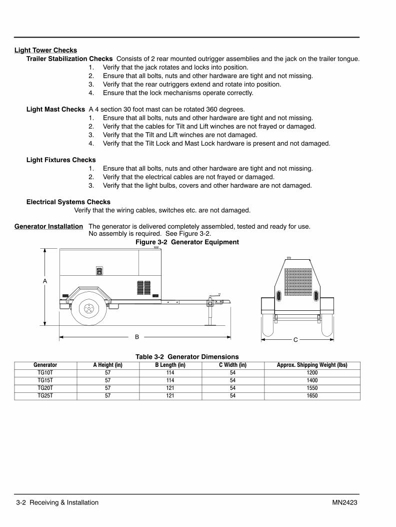
Generator Installation The generator is delivered completely assembled, tested and ready for use. No assembly is required. See Figure 3-2.
Figure 3-2 Generator Equipment
A
B C
Table 3-2 Generator DimensionsGenerator A Height (in) B Length (in) C Width (in) Approx. Shipping Weight (lbs)
TG10T 57 114 54 1200TG15T 57 114 54 1400TG20T 57 121 54 1550TG25T 57 121 54 1650
Receiving & Installation 3-3MN2423
Equipment ChecksThese checks should be performed before first service, after 25 hours of operation and every 100operating hours thereafter.
Trailer Checks Single axle trailer with leaf springs and two tires.1. Verify that the hitch mechanism on the trailer opens and closes freely and is securely
fastened to the trailer tongue.2. Verify that the safety chains are securely fastened to the trailer tongue.3. Verify that the trailer lighting connector and harness are present and are not damaged
(see Figure 3-5).4. Verify that trailer lights are not broken or damaged.5. Verify that the trailer tires are properly inflated (32 psi).6. Verify that the lug nuts for each wheel are properly torqued to 90 lb−ft.7. Verify that the enclosure is securely fastened to the trailer frame.
Ensure that all bolts, nuts and other hardware are tight and not missing.
Engine/Generator Checks Liquid cooled diesel engine.1. Refer to the engine manual for maintenance check procedures to ensure all fluid levels
are correct before each use.2. Verify that electrical receptacles, switches and circuit breakers are not damaged.3. Ensure switches and breakers are in the Off position before engine starting.
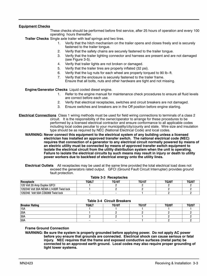
Electrical Connections Class 1 wiring methods must be used for field wiring connections to terminals of a class 2circuit. It is the responsibility of the owner/operator to arrange for these procedures to beperformed by a licensed electrical contractor and ensure conformance to all applicable codesincluding local codes peculiar to your municipality/city/county and state. Wire size and insulationtype should be as required by NEC (National Electrical Code) and local codes.
WARNING: Never connect this equipment to the electrical system of any building unless a licensedelectrician has installed an approved transfer switch. The national electrical code (NEC)requires that connection of a generator to any electrical circuit normally powered by means ofan electric utility must be connected by means of approved transfer switch equipment toisolate the electrical circuit from the utility distribution system when the unit is operating.Failure to isolate the electrical circuits by such means may result in injury or death to utilitypower workers due to backfeed of electrical energy onto the utility lines.
Electrical Outlets All receptacles may be used at the same time provided the total electrical load does notexceed the generators rated output. GFCI (Ground Fault Circuit Interrupter) provides groundfault protection.
Table 3-3 ReceptaclesReceptacle TG8LT TG10T TG15T TG20T TG25T120 Volt 20 Amp Duplex GFCI 1 2 2 2 2120/240 Volt 30A NEMA L1430R Twist lock 1 2 2 2 2120/240 Volt 50A CS6369 Twist lock – – 1 2 2
Table 3-4 Circuit BreakersBreaker Rating TG8LT TG10T TG15T TG20T TG25T15A 1 1 1 1 120A 1 2 2 2 230A 2 2 1 2 250A – – 1 2 2
Frame Ground ConnectionWARNING: Be sure the system is properly grounded before applying power. Do not apply AC power
before you ensure that grounds are connected. Electrical shock can cause serious or fatalinjury. NEC requires that the frame and exposed conductive surfaces (metal parts) beconnected to an approved earth ground. Local codes may also require proper grounding oflight tower systems.
3-4 Receiving & Installation MN2423
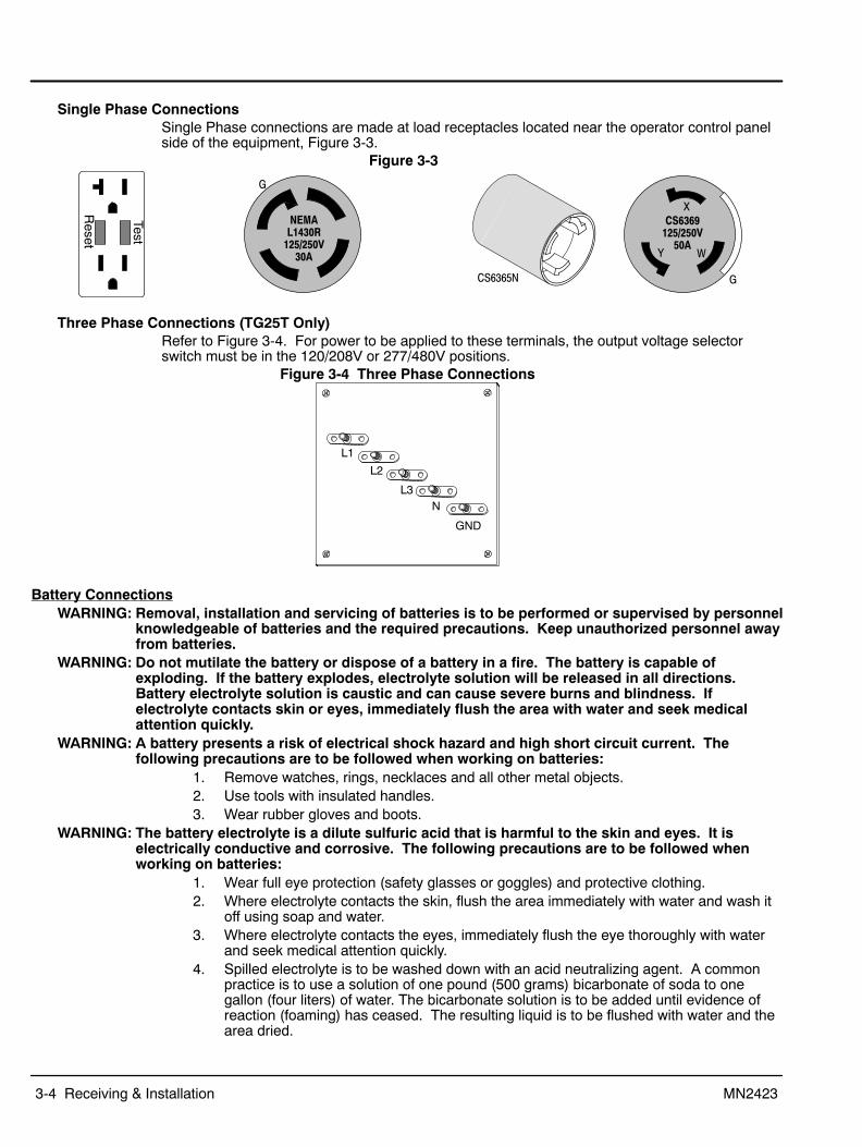
Single Phase ConnectionsSingle Phase connections are made at load receptacles located near the operator control panelside of the equipment, Figure 3-3.
Figure 3-3
Test
Reset
NEMAL1430R
125/250V30A
CS6365N
G
G
CS6369125/250V
50A
X
Y W
Three Phase Connections (TG25T Only)Refer to Figure 3-4. For power to be applied to these terminals, the output voltage selectorswitch must be in the 120/208V or 277/480V positions.
Figure 3-4 Three Phase Connections
L1
L2
L3N
GND
Battery ConnectionsWARNING: Removal, installation and servicing of batteries is to be performed or supervised by personnel
knowledgeable of batteries and the required precautions. Keep unauthorized personnel awayfrom batteries.
WARNING: Do not mutilate the battery or dispose of a battery in a fire. The battery is capable ofexploding. If the battery explodes, electrolyte solution will be released in all directions.Battery electrolyte solution is caustic and can cause severe burns and blindness. Ifelectrolyte contacts skin or eyes, immediately flush the area with water and seek medicalattention quickly.
WARNING: A battery presents a risk of electrical shock hazard and high short circuit current. Thefollowing precautions are to be followed when working on batteries:
1. Remove watches, rings, necklaces and all other metal objects.2. Use tools with insulated handles.3. Wear rubber gloves and boots.
WARNING: The battery electrolyte is a dilute sulfuric acid that is harmful to the skin and eyes. It iselectrically conductive and corrosive. The following precautions are to be followed whenworking on batteries:
1. Wear full eye protection (safety glasses or goggles) and protective clothing.2. Where electrolyte contacts the skin, flush the area immediately with water and wash it
off using soap and water.3. Where electrolyte contacts the eyes, immediately flush the eye thoroughly with water
and seek medical attention quickly.4. Spilled electrolyte is to be washed down with an acid neutralizing agent. A common
practice is to use a solution of one pound (500 grams) bicarbonate of soda to onegallon (four liters) of water. The bicarbonate solution is to be added until evidence ofreaction (foaming) has ceased. The resulting liquid is to be flushed with water and thearea dried.

Receiving & Installation 3-5MN2423
WARNING: A battery presents a risk of fire because they generate hydrogen gas. Hydrogen gas isextremely explosive. Never jump start a battery, smoke in the area around the battery orcause any spark to occur in the area around the battery. The following precautions are to befollowed when working on batteries:
1. Do not smoke when near batteries.2. Do not cause flame or spark in battery area.3. Discharge static electricity from body before touching batteries by first touching a
grounded metal surface.WARNING: Disconnect the battery’s ground terminal before working in the vicinity of the battery or
battery wires. Contact with the battery can result in electrical shock when a tool accidentaltouches the positive battery terminal or wire. The risk of such shock is reduced when theground lead is removed during installation and maintenance.
Procedure: The correct type battery must be installed in the battery compartment provided. Installation andservicing of batteries is to be performed or supervised by personnel knowledgeable of batteriesand the required precautions. Keep unauthorized personnel away from batteries.
1. Open access doors and locate battery tray.2. Remove the old battery.3. Install the new battery.4. Connect the positive lead to the positive (+) battery terminal.5. Connect the negative lead to the negative (−) battery terminal.6. Do not lay tools or metal parts on top of batteries.
Figure 3-5 Trailer Harness

3-6 Receiving & Installation MN2423

Section 4Operation
Operation 4-1MN2423
Towing the EquipmentWARNING: Never allow a person to ride in or on a trailer that is being towed. All states prohibit
passengers in towed vehicles. A person can fall off and be struck be another vehicle or runover by the towed trailer. Failure to observe this warning can result in death.
WARNING: Before using a tow vehicle, verify that the vehicle is designed for the load. Using a vehiclethat is too small is very dangerous. Be certain that it can handle the M.G.V.W. (MaximumGross Vehicle Weight) and the tongue weight for safe towing and braking.
WARNING: For a new trailer, the wheel lug nuts should be tightened to the proper torque specificationbefore use, after 50 miles of operation, after 100 miles of operation and periodically thereafter.Failure to check the lug nuts for proper tightness can result in an accident due to a wheelfalling from the trailer.
WARNING: Never operate a trailer or tow vehicle that has a loose, missing or broken lug nut. The traileris designed for safe operation with all lug nuts installed and all at the proper torque rating.Operating the trailer with one or more broken or missing lug nuts greatly increases the loadon the remaining nuts and can cause failure of the remaining nuts that can result in anaccident due to a wheel falling from the trailer.
Light TowerIntended Use The intended purpose of this light tower is to provide portable lighting where main utility power
supply is not available. It is not intended to connect to a building’s wiring system.Protection Single Phase circuit protection is provided within the light tower.Light Tower Towing Instructions See Figure 3-1 for component identification.Caution: Before towing, be sure that the mast, jack and outriggers are properly and securely stowed for
travel to prevent trailer damage. Also be sure that all enclosure doors are closed and locked.1. Mast must be stowed and locked (mast lock pin installed).2. If the light fixtures are mounted on the mast, reposition the light fixtures on the stowed
mast so the four light glass fronts are tilted away from the objects that may bepropelled from the tires during transportation.
3. Ensure that all light fixtures are properly secured to the mast.4. If outrigger jacks are extended, retract the jacks and rotate rear jacks up 90
degrees and lock into position. Pull Outrigger Locks and slide outriggers in allthe way until Outrigger Locks are locked.
5. Shut all doors on the engine compartment housing and latch the locks.6. Back the tow vehicle to within a few inches of the trailer coupler.7. Be sure the Coupler Handle is in the “UP” (open) position.8. Adjust the trailer jack for the height of the ball hitch on the tow vehicle.9. Back the tow vehicle so the trailer coupler is directly over the tow vehicle ball hitch.10. Lower the trailer so the trailer coupler rests securely on the ball hitch of the tow
vehicle.11. Move the Coupler Handle to the horizontal position and lock it in place to
securely hold the ball hitch of the tow vehicle. If this is not done properly, thetrailer may become unhitched when it is towed.
12. Retract the front jack, pull the jack pin and rotate the jack 90 degrees fromvertical to the horizontal position, making sure the self−locking pin reseats andthe jack is secured to the tow bar (stowed position).
13. Connect safety chains, making sure to cross them. If a safety chain is too long,simply twist it a few turns to shorten the chain before attaching to the towvehicle.
14. Connect the trailer light connector to the tow vehicle.15. Test the trailer lights to ensure they are operational.16. Check tires for proper inflation.17. Check wheel lug nuts for correct tightness (see Figure 4-1).
Wheel nuts/bolts should be torqued before the first road use and after each wheelremoval. Check and re−torque after the first 50 miles and again at 100 miles. Check periodically thereafter.
18. Verify that all jacks, outriggers, pins, cables, and light fixtures are in their proper placeand/or are secured.
19. Release the trailer wheel parking brake if equipped (optional equipment) and if set.

4-2 Operation MN2423
Light Tower Setup See Figure 3-1 for component identification.
WARNING: When erecting or stowing the mast assembly, be aware of the pinch points such as where thetower structures join or where the cable and winch are located. Careless operation can resultin injury. Keep extremities away from moving parts to avoid injury.
WARNING: Before erecting the mast assembly, be certain that the outriggers are properly set to stabilizethe unit and that they are secure and are not damaged. Erecting the mast without setting theoutriggers can cause the unit to tip over when raising the mast.
WARNING: Before erecting the mast assembly, be certain that there are no overhead wires. Contact withoverhead wiring presents an electrical shock hazard that may cause severe injury or death.
WARNING: Before erecting the mast assembly, be certain that there are no overhead obstructions thatthe mast will hit when raising it. Hitting an object (tree limb etc.) may damage the mast orcause the unit to tip over and may result in injury or property damage.
WARNING: Never move or reposition a light tower when the mast is extended or in the vertical position.Unless the mast is in its stowed position, it may contact overhead wires or cause the lighttower to be unbalanced or tip over.
1. With the Light Mast in its’ stowed position, install or reposition the four light fixtures tothe desired placement when the tower is raised.
2. Pull the Mast Lock pin so the mast is no longer secured in the stowed position.3. Pull the Tilt Lock pin so it is not in the way when the mast is raised.4. Use the Tilt Winch to raise the mast to the vertical position.5. Secure the mast in the vertical position by inserting and locking the the Tilt Lock pin.
The Tilt Lock pin must be installed and the mast secured in the vertical positionbefore the mast is raised.
6. Use the Lift Winch to raise the mast to the desired height. The winch is self−brakingand will lock in place automatically.
7. To rotate the lights to the desired position, loosen the Mast Rotation Lock on the collarof the mast, rotate the mast to the desired position and tighten the Mast Rotation Lock.
The light tower is now setup for operation.Light Tower Stow Procedure See Figure 3-1 for component identification.
1. Use the Lift Winch to lower the light tower to its’ lowest vertical position.The mast should come down slowly and smoothly. If slack develops in the cable or themast “hangs up”, stop immediately. Crank the winch in the reverse direction to take upslack in the cable, and determine the cause of the problem if possible. Try to lower themast again. If the problem persists do not continue, seek expert advise.
2. Loosen the Mast Rotation Lock and rotate the light mast so the lights face the rear ofthe trailer. Tighten the Mast Rotation Lock. (There is an indicator mark on the mast thatwill line up with the mast bracket indicator when the light fixtures are in the transportposition. This allows the mast, when lowered to the horizontal transport mode, to reston the brackets on the top of the engine compartment.)
3. Remove the Mast Lock pin so it will not interfere with the mast when it is tilted.4. Make sure the Tilt Winch cable is tight.5. Remove the Tilt Lock pin.6. Use the Tilt Winch to lower the mast to the horizontal position being careful not to pinch
the electrical light cables.7. Install the Mast Lock pin.8. Install the Tilt Lock pin.9. Adjust the light fixtures as needed for transport so the four light glass fronts are tilted
away from the objects that may be propelled from the tires during transportation.The mast is now in the stowed position for transport.

Operation 4-3MN2423
Light Tower Setup for Towing1. Adjust the two rear jacks to their shortest length.2. Pull the Jack Lock Pin for the right jack and rotate the jack to the horizontal position.
Lock the jack in this position using the Jack Lock Pin.3. Pull the Outrigger Lock for the right jack and push the right outrigger fully in. Lock the
outrigger using the Outrigger Lock.4. Repeat steps 2 and 3 for the left outrigger and jack.5. Shut all doors on the engine compartment housing and latch the locks.
The Trailer Outriggers are stowed and should appear as shown in Figure 3-1 left view. Refer to Towing Instructions at the beginning of this section to connect the POW’R LITE to thetow vehicle.
Towable GeneratorIntended Use The intended purpose of the generator set is to provide electrical power when the main utility power
supply is interrupted. Therefore, it is important that all the wiring that connects the generator set withyour house, transfer switch, distribution box, battery charger, etc. be properly installed.
Protection Circuit protection is provided within the generator. The power output connections are rated andsized according to the kW of the generator. The circuit protection provided will not protect thegenset or connected load in case of inadvertent connection to other power sources or power grid.
Generator Towing Instructions1. Be sure the generator is off.2. Shut all enclosure doors and latch the locks.3. Back the tow vehicle to within a few inches of the trailer coupler (Pintle or Ball).4. Be sure the Coupler Handle is in the “UP” (open) position or the Pintle Hook is Open.5. Adjust the trailer jack for the height of the hitch on the tow vehicle.6. Back the tow vehicle so the trailer coupler is directly over the tow vehicle ball hitch or
the Pintle hook.7. Lower the trailer so the trailer coupler rests securely on the ball hitch of the tow vehicle.
Move the Coupler Handle to the horizontal position and lock it in place to securely holdthe ball hitch of the tow vehicle. ORLatch the Pintle and lock the Pintle device securely.
Note: If this is not done properly, the trailer may become unhitched when it is towed.8. Retract the front jack, pull the jack pin and rotate the jack 90 degrees from vertical to
the horizontal position, making sure the self−locking pin reseats and the jack is securedto the tow bar (stowed position).
9. Connect safety chains, making sure to cross them. If a safety chain is too long, simplytwist it a few turns to shorten the chain before attaching to the tow vehicle.
10. Connect the trailer light connector to the tow vehicle.11. Test the trailer lights to ensure they are operational.12. Check tires for proper inflation.13. Check wheel lug nuts for correct tightness (see Lug Nut Tightness).
Wheel nuts/bolts should be torqued before the first road use and after each wheelremoval. Check and re−torque after the first 50 miles and again at 100 miles. Check periodically thereafter.
14. Verify that all jacks, pins, cables, and doors are secured and trailer tongue is level.15. Remove tire chocks (if used). These prevent the trailer from moving when parked.
Trailer Setup Carefully read all instructions before starting.1. Locate a suitable, level location with no overhead wires or obstructions.
The trailer is balanced so the majority of the weight rests on the tow bar (Jack). If on a minor incline, the safest way to position the trailer is to have the tow bar facingdown the incline (front of the trailer lower than the rear of the trailer).
2. Install tire chocks if used. These prevent the trailer from moving when parked.3. Disconnect the safety chains and the trailer light connector from the tow vehicle.4. Pull the pin on the front jack and rotate the jack 90 degrees to the vertical position.
Lock the jack in the vertical position using the pin to secure it.

4-4 Operation MN2423
5. Move the Coupler Handle to the vertical position to release the ball hitch. ORRelease the Pintle hook.
6. Use the jack to raise the trailer coupler from the ball hitch of the tow vehicle.7. The tow vehicle can now be moved away from the equipment.8. Use the jack to level the trailer for operation.
Lug Nut Tightness Be sure to use only the fasteners matched to the cone angle of your wheel (usually 60 or 90degrees.) The proper procedure for attaching your wheel is as follows, see Figure 4-1:
1. If a wheel is removed and installed, start each nut by hand to prevent cross threading.2. Tighten lug nuts in the following sequence.
a. Tighten each bolt in the sequence shown in Figure 4-1 and tighten to one half thetorque specified until all lug nuts are tightened to one half the torque.
b. Tighten each bolt in the sequence shown in Figure 4-1 and tighten to three fourthsthe torque specified until all lug nuts are tightened to three fourths the torque.
c. Tighten each bolt in the sequence shown in Figure 4-1 and tighten each to thespecified torque until all lug nuts are tightened to the correct torque.
Figure 4-1 Lug Nut Tightening Specifications
Description
1/2” Cone nut
5/8” Cone nut
5/8” Cone nut
3/4” Hex nut
4 Bolt 5 Bolt 6 Bolt 8 Bolt 10 Bolt
Tightening Sequence
Application
12” − 13” Wheel
14” − 16” Wheel
Flat Disc Wheel
Clamp Ring
Demountable Ring Clamp
Minimum Torque (ft−lbs.)
50
90
175
190
210
Maximum Torque (ft−lbs.)
65
120
225
210
260
Torque Specification
1
2
34
1
2
34
5 7
681
2
34
5
1
63
2
45
1
2
63
810
5
7 9
4
Voltage SelectionWARNING: High voltage is present whenever the engine is running. Electrical shock can cause serious
or fatal injury. Always stop engine before connecting or disconnecting power cords orexternal devices.
WARNING: High voltage is present whenever engine is running. Electrical shock can cause serious orfatal injury. Never operate electrical equipment while standing in water, on wet ground or withwet hands, feet or shoes or while barefoot.
Hard Wire Load Terminal Block, (TG25T Only, Figure 3-4)1. Ensure the generator is off.2. Place voltage select switch in the correct position 208/120, 240/120 or 480/277VAC,
Figure 4-3. To ensure the switch position is not accidentally changed, it should bepadlocked as shown in Figure 4-2.
Figure 4-2
Insert padlock through the hole in the handle.This activates an internal mechanism thatprevents handle rotation.
3. Carefully inspect all Individual load cables for broken insulation or other signs ofdamage. Never use a damaged cable. Replace it before usage.
Operation 4-5MN2423
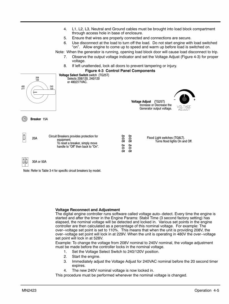
4. L1, L2, L3, Neutral and Ground cables must be brought into load block compartmentthrough access hole in base of enclosure.
5. Ensure that wires are properly connected and connections are secure.6. Use disconnect at the load to turn off the load. Do not start engine with load switched
“on”. Allow engine to come up to speed and warm up before load is switched on.Note: When the generator is running, opening load block door will cause load disconnect to trip.
7. Observe the output voltage indicator and set the Voltage Adjust (Figure 4-3) for propervoltage.
8. If left unattended, lock all doors to prevent tampering or injury.Figure 4-3 Control Panel Components
− +
Circuit Breakers provides protection forequipment.To reset a breaker, simply movehandle to “Off" then back to “On".
15
Voltage Select Switch switch (TG25T)Selects 208/120, 240/120 or 480/277VAC.
Voltage Adjust (TG25T) Increase or Decrease theGenerator output voltage.
On
Off
On
Off
On
Off
On
Off
Breaker 15A
20A
30A or 50A
Flood Light switches (TG8LT).Turns flood lights On and Off.
Note: Refer to Table 3‐4 for specific circuit breakers by model.
Voltage Reconnect and AdjustmentThe digital engine controller runs software called voltage auto−detect. Every time the engine isstarted and after the timer in the Engine Params: Stabil Time (3 second factory setting) haselapsed, the nominal voltage will be detected and locked in. Various set points in the enginecontroller are then calculated as a percentage of this nominal voltage. For example: Theover−voltage set point is set to 110%. This means that when the unit is providing 208V, theover−voltage set point will lock in at 229V. When the unit is operating in 480V the over−voltageset point will lock in at 528V.Example: To change the voltage from 208V nominal to 240V nominal, the voltage adjustmentmust be made before the controller locks in the nominal voltage.
1. Set the Voltage Select Switch to 240/120V position.2. Start the engine.3. Immediately adjust the Voltage Adjust for 240VAC nominal before the 20 second timer
expires.4. The new 240V nominal voltage is now locked in.
This procedure must be performed whenever the nominal voltage is changed.

4-6 Operation MN2423
Pre−Start Procedure Before attempting to start the equipment, several things must first be verified or performed. These are:1. Fill system fuel tank with clean, fresh diesel fuel.2. Fill engine crankcase to full mark with clean, fresh lubricating oil per engine
manufacturer operating guide.3. Radiator coolant should be checked at the beginning of each day and filled in
compliance with the engine manufacturer’s guidelines.4. Secure the equipment for operation.
a. Trailer mounted − block wheels to prevent accidental movement. Use jack (Figure 3-1) to level the equipment.
b. Adequate clearance must be provided for access doors to fully open.5. Place voltage select switch in the correct position 208/120, 240/120 or 480/277VAC
and pad lock it in position if required (Figure 4-2). (TG25T Only)6. Carefully inspect all Individual load cables for broken insulation or other signs of
damage. Never use a damaged cable. Replace it before usage.7. L1, L2, L3, Neutral and Ground cables must be brought into load block compartment
through access hole in base of enclosure. (TG25T Only, Figure 3-4)8. Ensure that wires are properly connected and connections are secure.9. Ensure that an external ground connection is made when required for safety.10. Use disconnect at the load to turn off the load. Do not start engine with load switched
“On”. and warm up before load is switched on.11. Manually start the engine, allow engine to come up to speed and perform the Voltage
Reconnect and Adjustment within the allotted time.12. Stop the engine.
Figure 4-4 Operator Panel
On
Off
On
Off
On
Off
On
Off
TG8LT−TG20T TG25T
− +
Note: For reference only. See Table 3-4 for appropriate breakers.
Operating Procedures The engine−generator controller is designed to start and stop an engine from either AUTO“Automatic” mode or Manual “NOT IN AUTO”. Refer to Figure 4-5.
Manual Start Procedure1. Press AUTO until the Green LED is not lit above the button.2. Press “Start”.3. The controller will start the engine.
Manual Stop Procedure1. Use disconnect at the load to turn OFF the load. Allow equipment cool down if needed.2. Press “Stop”.
AUTO Start Procedure1. Press AUTO until the Green LED is lit above the button.
In Auto mode, the equipment will start when the remote start input closes.2. In Auto mode, the equipment will stop when the remote start input opens.

Operation 4-7MN2423
Flood Light Operation:1. When the engine reaches operating speed and is operating smoothly, turn on one light
and wait one second turn on another light and wait one second etc. until the flood lightsare all on.
2. Observe the operation of each flood light and replace defective bulbs if required. Tochange a bulb, refer to Section 5 of this manual.
Note: Vaporous flood lights may require 5 to 15 minutes to warm up and produce full light output.
Operating Checks:3. Check diesel fuel level and shut off the engine and add if necessary. Check engine oil
each time fuel is added. Never allow the engine to run out of fuel or to run low of oil.
Receptacle Panel Load Connections, see Figure 3-3.1. 120/240VAC voltage is present at the receptacle panel only when equipment is
running.2. Carefully inspect all Individual load cables for broken insulation or other signs of
damage. Never use a damaged cable. Replace it before usage.3. Individual load cables may be routed to the receptacle compartment.4. Individual load cables may be connected or disconnected while equipment is running.
Use extreme care not to touch any electrical wire or terminal to avoid shock hazard.5. Keep Engine Compartment doors closed at all times. This prevents rain or other
harmful elements from entering the compartment.
AC Breaker (on panel) that when tripped turns off all AC power to Mast Lights and ACReceptacles. Manually trip the breaker “Off” to immediately interrupt all AC power. If breaker trips due to overload, first clear the overload condition. To reset the breaker, place it first in the off position then to the ON position.
Engine Stop Procedure: (see Figure 4-5)Caution: Never stop the engine with any of the lights on, or with any electrical load connected, as
damage may result.
1. Turn OFF all floodlight switches and unplug all loads from receptacle panel.Note: After turning OFF a light, do not attempt to turn the light ON until after a 10−25 minute cool
down period. Turning a light OFF then ON may damage the light bulb.2. If the engine has been operating for several hours under load, allow it to operate
unloaded for at least five minutes to reduce coolant temperature.3. Press the STOP Position to shut down engine.
WARNING: Light fixtures become extremely hot during use. To prevent severe burns, do not touch lightfixtures, bulbs or other components until they have cooled and no longer present a burn hazard.Wear protective clothing when placing the tower in the stowed position after use and do not allowany person to touch the light fixtures.
WARNING: When erecting or stowing the mast assembly, be aware of the pinch points such as where thetower structures join or where the cable and winch are located. Careless operation can resultin injury. Keep extremities away from moving parts to avoid injury.
WARNING: The mast should come down slowly and smoothly. If slack develops in the cable or the mast“hangs up”, stop immediately. Crank the winch in the reverse direction to take up slack in thecable, and determine the cause of the problem if possible. Try to lower the mast again. If the problem persists do not continue, seek expert advise. Cable slack can allow the lighttower to fall unexpectedly which may result in injury or damage.
4-8 Operation MN2423
Digital Engine Controller Description EM0046A68 (MRS)
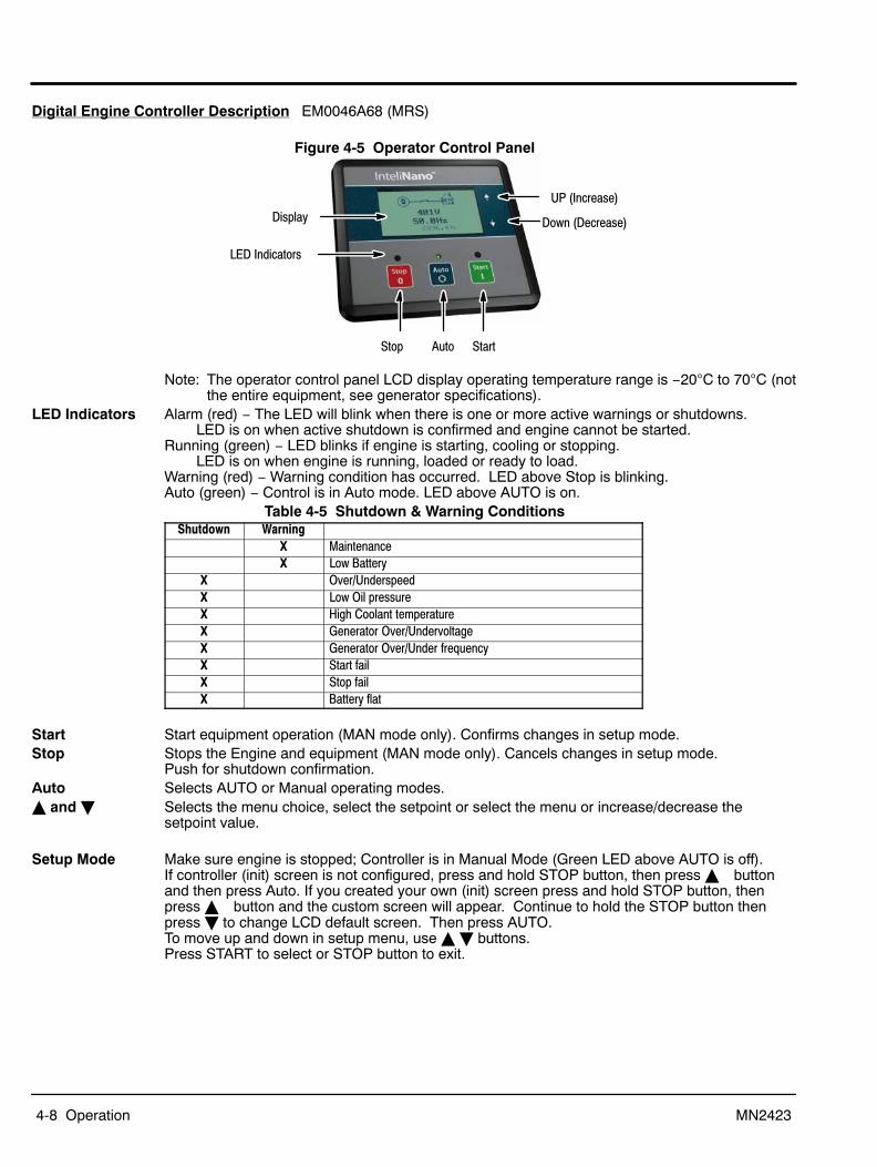
Figure 4-5 Operator Control Panel
Stop
Display
LED Indicators
Auto Start
UP (Increase)
Down (Decrease)
Note: The operator control panel LCD display operating temperature range is −20C to 70C (notthe entire equipment, see generator specifications).
LED Indicators Alarm (red) − The LED will blink when there is one or more active warnings or shutdowns. LED is on when active shutdown is confirmed and engine cannot be started.
Running (green) − LED blinks if engine is starting, cooling or stopping. LED is on when engine is running, loaded or ready to load.
Warning (red) − Warning condition has occurred. LED above Stop is blinking.Auto (green) − Control is in Auto mode. LED above AUTO is on.
Table 4-5 Shutdown & Warning ConditionsShutdown Warning
X MaintenanceX Low Battery
X Over/UnderspeedX Low Oil pressureX High Coolant temperatureX Generator Over/UndervoltageX Generator Over/Under frequencyX Start failX Stop failX Battery flat
Start Start equipment operation (MAN mode only). Confirms changes in setup mode.Stop Stops the Engine and equipment (MAN mode only). Cancels changes in setup mode.
Push for shutdown confirmation.Auto Selects AUTO or Manual operating modes.� and � Selects the menu choice, select the setpoint or select the menu or increase/decrease the
setpoint value.
Setup Mode Make sure engine is stopped; Controller is in Manual Mode (Green LED above AUTO is off). If controller (init) screen is not configured, press and hold STOP button, then press � buttonand then press Auto. If you created your own (init) screen press and hold STOP button, thenpress � button and the custom screen will appear. Continue to hold the STOP button thenpress � to change LCD default screen. Then press AUTO. To move up and down in setup menu, use � � buttons.Press START to select or STOP button to exit.
Operation 4-9MN2423
Operating Mode Use the AUTO button to select AUTO or MANUAL mode.AUTO − Green LED above AUTO will be on. Start and Stop buttons are ignored.MAN − Green LED above AUTO will be off.
Press Start to manually start the equipment immediately.Press STOP to stop the equipment immediately.
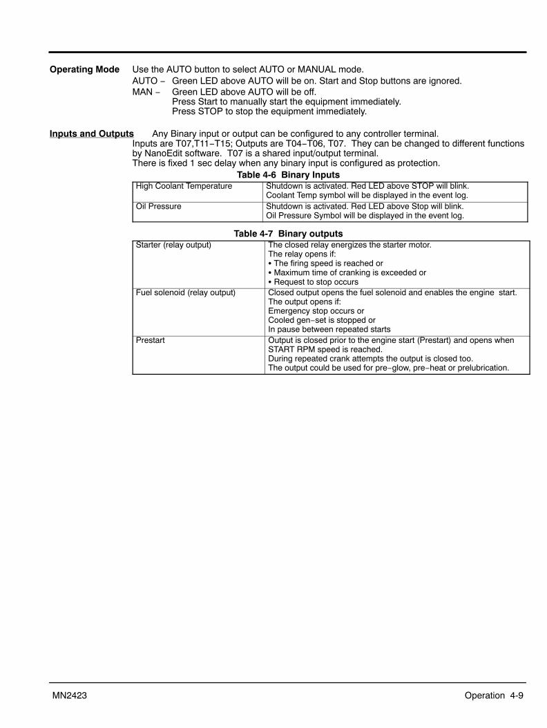
Inputs and Outputs Any Binary input or output can be configured to any controller terminal. Inputs are T07,T11−T15; Outputs are T04−T06, T07. They can be changed to different functionsby NanoEdit software. T07 is a shared input/output terminal. There is fixed 1 sec delay when any binary input is configured as protection.
Table 4-6 Binary InputsHigh Coolant Temperature Shutdown is activated. Red LED above STOP will blink.
Coolant Temp symbol will be displayed in the event log.Oil Pressure Shutdown is activated. Red LED above Stop will blink.
Oil Pressure Symbol will be displayed in the event log.
Table 4-7 Binary outputsStarter (relay output) The closed relay energizes the starter motor.
The relay opens if:� The firing speed is reached or� Maximum time of cranking is exceeded or� Request to stop occurs
Fuel solenoid (relay output) Closed output opens the fuel solenoid and enables the engine start.The output opens if:Emergency stop occurs orCooled gen−set is stopped orIn pause between repeated starts
Prestart Output is closed prior to the engine start (Prestart) and opens whenSTART RPM speed is reached.During repeated crank attempts the output is closed too.The output could be used for pre−glow, pre−heat or prelubrication.
4-10 Operation MN2423
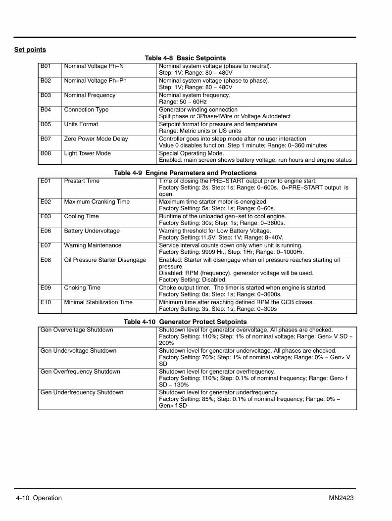
Set pointsTable 4-8 Basic Setpoints
B01 Nominal Voltage Ph−N Nominal system voltage (phase to neutral). Step: 1V; Range: 80 − 480V
B02 Nominal Voltage Ph−Ph Nominal system voltage (phase to phase). Step: 1V; Range: 80 − 480V
B03 Nominal Frequency Nominal system frequency. Range: 50 − 60Hz
B04 Connection Type Generator winding connectionSplit phase or 3Phase4Wire or Voltage Autodetect
B05 Units Format Setpoint format for pressure and temperatureRange: Metric units or US units
B07 Zero Power Mode Delay Controller goes into sleep mode after no user interaction Value 0 disables function. Step 1 minute; Range: 0−360 minutes
B08 Light Tower Mode Special Operating Mode.Enabled: main screen shows battery voltage, run hours and engine status
Table 4-9 Engine Parameters and ProtectionsE01 Prestart Time Time of closing the PRE−START output prior to engine start.
Factory Setting: 2s; Step: 1s; Range: 0−600s. 0=PRE−START output isopen.
E02 Maximum Cranking Time Maximum time starter motor is energized. Factory Setting: 5s; Step: 1s; Range: 0−60s.
E03 Cooling Time Runtime of the unloaded gen−set to cool engine.Factory Setting: 30s; Step: 1s; Range: 0−3600s.
E06 Battery Undervoltage Warning threshold for Low Battery Voltage. Factory Setting:11.5V; Step: 1V; Range: 8−40V.
E07 Warning Maintenance Service interval counts down only when unit is running.Factory Setting: 9999 Hr.; Step: 1Hr; Range: 0−1000Hr.
E08 Oil Pressure Starter Disengage Enabled: Starter will disengage when oil pressure reaches starting oilpressure.Disabled: RPM (frequency), generator voltage will be used. Factory Setting: Disabled.
E09 Choking Time Choke output timer. The timer is started when engine is started.Factory Setting: 0s; Step: 1s; Range: 0−3600s.
E10 Minimal Stabilization Time Minimum time after reaching defined RPM the GCB closes.Factory Setting: 3s; Step: 1s; Range: 0−300s
Table 4-10 Generator Protect SetpointsGen Overvoltage Shutdown Shutdown level for generator overvoltage. All phases are checked.
Factory Setting: 110%; Step: 1% of nominal voltage; Range: Gen> V SD −200%
Gen Undervoltage Shutdown Shutdown level for generator undervoltage. All phases are checked.Factory Setting: 70%; Step: 1% of nominal voltage; Range: 0% − Gen> VSD
Gen Overfrequency Shutdown Shutdown level for generator overfrequency. Factory Setting: 110%; Step: 0.1% of nominal frequency; Range: Gen> fSD − 130%
Gen Underfrequency Shutdown Shutdown level for generator underfrequency. Factory Setting: 85%; Step: 0.1% of nominal frequency; Range: 0% −Gen> f SD

Operation 4-11MN2423
Figure 4-6 Wiring Diagram

4-12 Operation MN2423

Section 5Troubleshooting and Maintenance
Troubleshooting and Maintenance 5-1MN2423
WARNING: Never “jump start” a equipment to start the engine. If the battery charge is insufficient tostart the engine, charge or replace the battery and try to restart. Jump starting a battery cancause the battery to explode and cause severe injury or death to anyone in the area.
Caution: If a dead battery is suspected charge battery (or replace), and then attempt starting. Damageto engine control may result from jump starting.
Maintenance This manual contains only very minimal engine maintenance instructions. Refer to the enginemanufacturer’s owner’s manual for specific engine maintenance instructions for your equipment.Any maintenance instructions or recommendations in the engine owner’s manual takeprecedence over any of the following general recommendations.General:
1. Inspect the fuel system for leaks. Replace all defective components immediately.2. Inspect and replace any fuel line that shows signs of deterioration.3. Inspect all the fuel clamps to ensure they are tight.4. Make sure the fuel cap fits snugly on the fuel tank and that the fuel tank contains no
leaks.5. Inspect and clean the battery posts and the associated battery cable terminals.6. Inspect the external wire cables and connectors used with the equipment for cuts,
fraying, or loose connections. Repair or replace any problems prior to using the unit.
Engine:1. Clean and/or replace any fuel, oil, and/or air filters per the engine manufacturers’
guidelines.2. Check oil level regularly; at least every 5 to 8 operating hours. Maintain the proper oil
level.3. Change the oil as is recommended in the engine manufacturer’s owner’s manual.4. Clean the cooling fins on the engine to keep the engine’s heat dissipation potential at
it’s maximum.5. Inspect and clean all governor and fuel supply linkages so they operate properly.
Alternator: ( also called Generator End)This equipment must be run at its proper speed to obtain the correct electrical power at itsoutput. All engines have a tendency to slow down when a load is applied to it. The enginegovernor is designed to hold the operating speed as nearly constant as possible. When theelectrical load is increased, the engine is more heavily loaded and engine speed drops slightly.This slight decrease in engine speed results in a slight decrease in equipment voltage andfrequency output. This voltage and frequency variation has no appreciable effect in the operationof motors, lights, and most appliances and tools. However, timing devices and clocks may notkeep perfect time.
1. Clean the equipment and remove any and all dust, dirt, or other foreign material.2. Inspect and clean the cooling air intake and exhaust louvers of the equipment end.
Make sure they are clean. Remove dirt or any buildup that may restrict the cooling airflow.
3. Clean the equipment and its components with a damp cloth or sponge. Never use a water hose or pressure washer as this may damage electricalcomponents.
4. Inspect and replace any control panel components that are broken or not workingproperly (receptacles, circuit breakers, switches, etc.)
Flood Light Bulb ReplacementWARNING: Light fixtures become extremely hot during use. To prevent severe burns, do not touch light
fixtures, bulbs or other components until they have cooled and no longer present a burn hazard.Wear protective clothing when placing the tower in the stowed position after use and do not allowany person to touch the light fixtures.
Refer to Section 4 of this manual for the procedures if you are not familiar with these steps.1. Stop the generator.2. Lower the mast.3. Tilt the mast down to the stowed position.4. Wait until the fixtures and bulbs have cooled sufficiently and replace the defective bulb.

5-2 Troubleshooting and Maintenance MN2423
Cleaning Keeping your equipment clean is an important part of good operation. If dirt buildup is notremoved, the equipment will run hotter than normal and it’s life is reduced. The following are general guidelines for cleaning.
Maintenance Schedule
Maintenance OperationMaintenance Interval
10 Hrs(Daily) 50 Hrs. 125 Hrs. 250 Hrs. 500 Hrs. 1000
Hrs.2500Hrs.
Safety Guard Inspection � �Fluid Leak Inspection − General � �Oil Level Check � �Coolant Level Check � �Fan/Alternator Belt Inspection � �Radiator Core Inspection � �Air Filter Element Check (Dry Type)
Air Filter Check (Oil Bath Type) �Oil Replacement − Initial only � �Oil Filter Replacement − Initial only � �Oil Replacement � �Check mast cables. Check lighting lead wires (TG8LT)
��
Oil Filter Replacement �Fuel Filter Replacement �Coolant Hose Replacement �Fan/Alternator Belt Tension Adjustment �Valve Adjustment �Fan/Alternator Belt Replacement �Fuel Injection System Adjustments �Grease the mast collar grease fitting (TG8LT) �Clean Fuel Tank � �Grease trailer bearings �Coolant Replacement � �Replace Timing Belt �
� Add fluid(s) as needed.� After inspection, adjust, repair or replace as needed.� Clean as often as needed. Replace air filter if air flow is restricted or one (1) year. Service oil bath filter element (upper and lower) as needed. Replace reservoir oil as needed.
Note: In dusty conditions, service the oil bath air filter every four (4) hours of operation.� See engine manufactures recommendation.� Replace coolant every 2500 hours or 2 years.

Troubleshooting and Maintenance 5-3MN2423
Equipment Troubleshooting GuideTable 5-1 Light Mast Troubleshooting Guide
Problem Possible Cause RemedyMast will not raise to operating position. Mast Lock Pin still in place.
Defective winch or cable.Remove pin.Have winch and cable examined by a qualified mechanic. Replace if required.
Mast will not telescope to desired height. Defective winch or broken cable. Have winch and cable examined by a qualified mechanic. Replace if required.
Mast will not rotate. Bolt/nut on bottom of mast may be tootight.Mast rotation collar needs to be greased.
Back off on nut setting slightly and try to rotate mast.
Apply grease to grease fitting.Table 5-2 Generator Troubleshooting Guide
Problem Possible Cause RemedyEngine will not turn over. Loose battery cables or dead battery.
Engine seized due to loss of oil.
Recharge or replace battery. Check battery cable at batteryterminals and starter for tightness.Have unit inspected by qualified mechanic.
Engine turns over but will not start. Fuel tank empty.Clogged fuel filter.Fuel line connections leaking.Heater plug element burned out.Suspect contaminated fuel.
Fill tank and bleed fuel system.Replace filter, use winter grade fuel (weather cold). Bleed out air.Tighten all fuel fittings and bleed air from fuel system.Replace heater plug.The fuel tank has a drain valve on the bottom side of the trailer.Drain and replace the fuel.
Engine difficult to start. Battery charge low or cables loose.Motor oil too thick in cold winter.Clogged fuel filter or fuel cloudy in coldweather.Fuel line connections leaking.
Replace/recharge battery. Tighten cable connections.Use proper winter grade oil.Replace filter and bleed air from System. Use winter grade diesel incold weather.Tighten all fuel fittings and bleed air from fuel system.
Rough running engine with low poweroutput.
Clogged fuel filter or leaking fuel lineconnections.Exhaust system clogged.Air filter clogged.Fuel injectors nozzles clogged or stuck.Valve clearance needs adjusting or valvesprings broken.Governor or injector pump defective.
Tighten all fuel fittings and bleed air from fuel system.
Check muffler and exhaust manifold, clear any obstructions.Replace air filter.Have unit checked by qualified mechanic.Have unit checked by qualified mechanic.
Have unit checked by qualified mechanic.
Engine runs but produces excessive thicksmoke.
Crankcase oil level too high.Compression low.
Drain oil level to full mark on dipstick.Have qualified mechanic check unit for broken or seized rings orimproper valve clearances.
Engine runs but battery voltage low. Battery charger or alternator failure. Have qualified mechanic repair or replace.Engine runs but lights do not come on. Circuit breakers tripped or light switches
in "OFF" position.Loose connections in light wiring.Loose connection in ballast box wiring.Bulbs burned out.Defective AC generator.Engine speed too low.
Defective ballast.
Check circuit breaker, press reset button if tripped, turn on lightswitches.Check junction box connections for security.Have a trained electrician inspect ballast box and wiring.Replace bulbs.Have a trained electrician inspect generator.Have a qualified mechanic check unit and, if necessary, resetengine speed to 1800 RPM or 60 HZ.Have a trained electrician inspect the ballast system.
Unusual noises coming from thegenerator.
Generator bearing or cooling fandefective.
Have a qualified mechanic inspect the generator.
An electric shock occurs when the lighttower or housing is touched.
Short circuit in wiring system. IMMEDIATELY stop using the light tower.IMMEDIATELY have the unit inspected by a qualified mechanic.
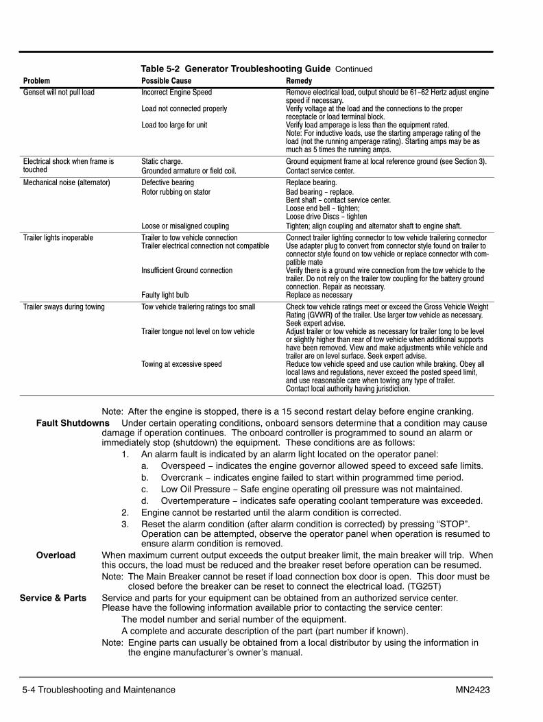
5-4 Troubleshooting and Maintenance MN2423
Table 5-2 Generator Troubleshooting Guide ContinuedProblem Possible Cause RemedyGenset will not pull load Incorrect Engine Speed
Load not connected properly
Load too large for unit
Remove electrical load, output should be 61-62 Hertz adjust enginespeed if necessary.Verify voltage at the load and the connections to the properreceptacle or load terminal block.Verify load amperage is less than the equipment rated. Note: For inductive loads, use the starting amperage rating of theload (not the running amperage rating). Starting amps may be asmuch as 5 times the running amps.
Electrical shock when frame istouched
Static charge.Grounded armature or field coil.
Ground equipment frame at local reference ground (see Section 3).Contact service center.
Mechanical noise (alternator) Defective bearingRotor rubbing on stator
Loose or misaligned coupling
Replace bearing.Bad bearing - replace. Bent shaft - contact service center. Loose end bell - tighten; Loose drive Discs - tightenTighten; align coupling and alternator shaft to engine shaft.
Trailer lights inoperable Trailer to tow vehicle connectionTrailer electrical connection not compatible
Insufficient Ground connection
Faulty light bulb
Connect trailer lighting connector to tow vehicle trailering connectorUse adapter plug to convert from connector style found on trailer toconnector style found on tow vehicle or replace connector with compatible mateVerify there is a ground wire connection from the tow vehicle to thetrailer. Do not rely on the trailer tow coupling for the battery groundconnection. Repair as necessary.Replace as necessary
Trailer sways during towing Tow vehicle trailering ratings too small
Trailer tongue not level on tow vehicle
Towing at excessive speed
Check tow vehicle ratings meet or exceed the Gross Vehicle WeightRating (GVWR) of the trailer. Use larger tow vehicle as necessary.Seek expert advise.Adjust trailer or tow vehicle as necessary for trailer tong to be levelor slightly higher than rear of tow vehicle when additional supportshave been removed. View and make adjustments while vehicle andtrailer are on level surface. Seek expert advise.Reduce tow vehicle speed and use caution while braking. Obey alllocal laws and regulations, never exceed the posted speed limit,and use reasonable care when towing any type of trailer. Contact local authority having jurisdiction.
Note: After the engine is stopped, there is a 15 second restart delay before engine cranking.Fault Shutdowns Under certain operating conditions, onboard sensors determine that a condition may cause
damage if operation continues. The onboard controller is programmed to sound an alarm orimmediately stop (shutdown) the equipment. These conditions are as follows:
1. An alarm fault is indicated by an alarm light located on the operator panel:a. Overspeed − indicates the engine governor allowed speed to exceed safe limits.b. Overcrank − indicates engine failed to start within programmed time period.c. Low Oil Pressure − Safe engine operating oil pressure was not maintained.d. Overtemperature − indicates safe operating coolant temperature was exceeded.
2. Engine cannot be restarted until the alarm condition is corrected.3. Reset the alarm condition (after alarm condition is corrected) by pressing “STOP”.
Operation can be attempted, observe the operator panel when operation is resumed toensure alarm condition is removed.
Overload When maximum current output exceeds the output breaker limit, the main breaker will trip. Whenthis occurs, the load must be reduced and the breaker reset before operation can be resumed.Note: The Main Breaker cannot be reset if load connection box door is open. This door must be
closed before the breaker can be reset to connect the electrical load. (TG25T)Service & Parts Service and parts for your equipment can be obtained from an authorized service center.
Please have the following information available prior to contacting the service center:The model number and serial number of the equipment.A complete and accurate description of the part (part number if known).
Note: Engine parts can usually be obtained from a local distributor by using the information inthe engine manufacturer’s owner’s manual.

Appendix AWiring Diagrams
Wiring Diagrams A-1MN2423
Replacement Parts Engine parts are identified in the engine manual that was provided with your generator set.
IMPORTANT: Fuses are installed in the control box to protect the engine controller and associatedcontrol circuits. When replacing fuses, use the exact replacement fuse (manufacturer andpart number).
Wiring Diagrams Wiring diagrams for these generators are contained on the following pages of this appendix.

A-2 Wiring Diagrams MN2423
Figure A-1 TG8LT

Wiring Diagrams A-3MN2423
Figure A-2 TG8LT

A-4 Wiring Diagrams MN2423
Figure A-3 TG8LT

Wiring Diagrams A-5MN2423
Figure A-4 TG10T

A-6 Wiring Diagrams MN2423
Figure A-5 TG10T

Wiring Diagrams A-7MN2423
Figure A-6 TG15T

A-8 Wiring Diagrams MN2423
Figure A-7 TG15T

Wiring Diagrams A-9MN2423
Figure A-8 TG20T
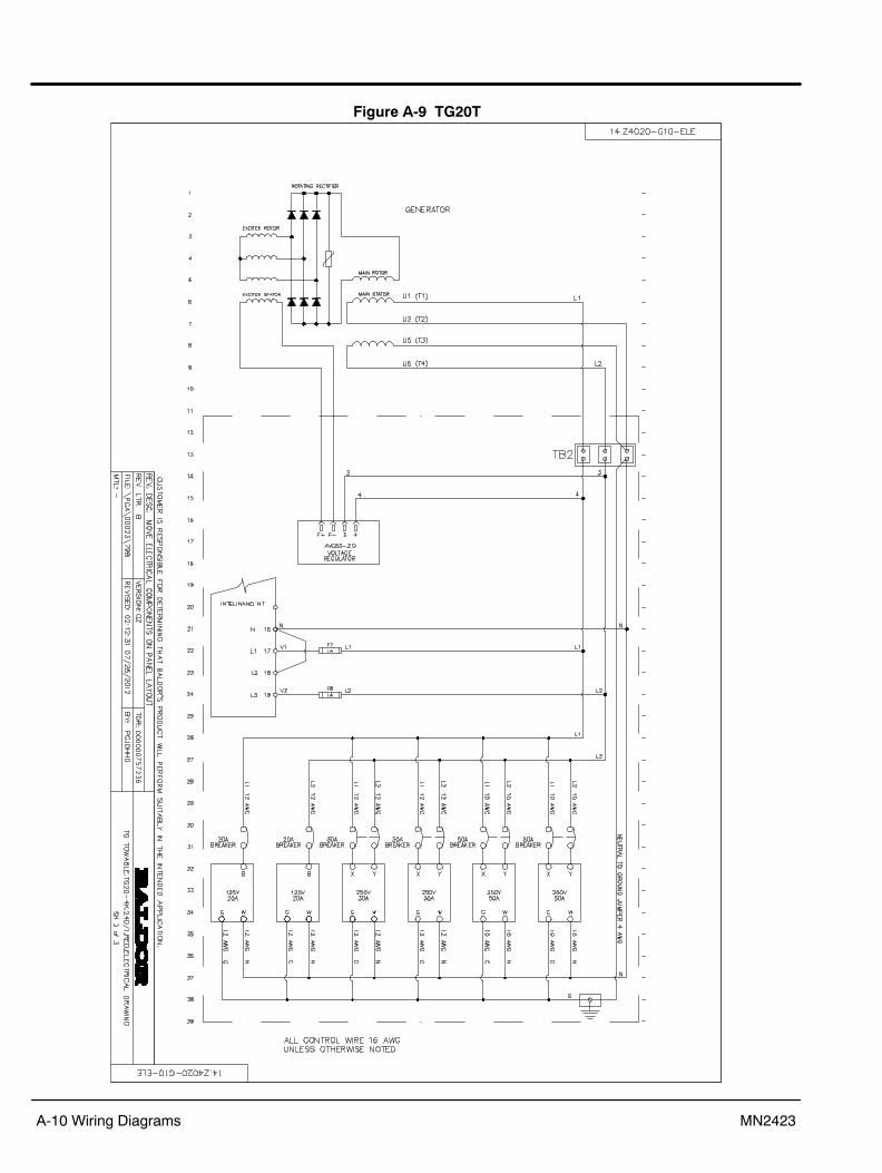
A-10 Wiring Diagrams MN2423
Figure A-9 TG20T

Wiring Diagrams A-11MN2423
Figure A-10 TG25T

A-12 Wiring Diagrams MN2423
Figure A-11 TG25T
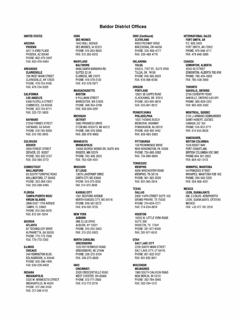
Baldor District Offices

2012 Baldor Electric CompanyMN2423
All rights reserved. Printed in USA8/12
WARNING:CALIFORNIA PROPOSITION 65 WARNING:
Engine exhaust from this product contains chemicals knownto the state of California to cause cancer, birth defects andother reproductive harm.
WARNING:CALIFORNIA PROPOSITION 65 WARNING:
Battery posts, terminals and related accessories are known tothe state of California to cause cancer, birth defects and otherreproductive harm.
P.O. Box 2400 Fort Smith, AR 72902-2400 USA Ph: (1) 479.646.4711, Fax: (1)479.648.5792
www.baldor.com