toward industrial-strength automated … industrial-strength automated design of analog ... • a...
TRANSCRIPT

1
TOWARD INDUSTRIAL-STRENGTH AUTOMATED DESIGN OF ANALOG CIRCUITS BY MEANS OF GENETIC
PROGRAMMING
GPTP-2004—ANN ARBOR FRIDAY, MAY 14, 2004
John R. Koza Lee W. Jones
Martin A. Keane

2
GENETIC PROGRAMMING OVER 15-YEAR PERIOD 1987–2002
System Period
of usage
Petacycles (1015cycles) per day for
entire system
Speed-up over
previous system
Speed-up over first system in this table
Human-competitive
results
Serial Texas Instruments LISP machine
1987–1994
0.00216 1 (base) 1 (base) 0
64-node Transtech transputer parallel machine
1994–1997
0.02 9 9 2
64-node Parsytec parallel machine
1995–2000
0.44 22 204 12
70-node Alpha parallel machine
1999–2001
3.2 7.3 1,481 2
1,000-node Pentium II parallel machine
2000–2002
30.0 9.4 13,900 12

3
PROGRESSION OF RESULTS System Period Speed-
upQualitative nature of the results produced by genetic programming
Serial LISP machine
1987–1994
1 (base) • Toy problems of the 1980s and early 1990s from the fields of artificial intelligence and machine learning
64-node Transtech 8-biy transputer
1994–1997
9 •Two human-competitive results involving one-dimensional discrete data (not patent-related)
64-node Parsytec parallel machine
1995–2000
22 • One human-competitive result involving two-dimensional discrete data • Numerous human-competitive results involving continuous signals analyzed in the frequency domain • Numerous human-competitive results involving 20th-century patented inventions
70-node Alpha parallel machine
1999–2001
7.3 • One human-competitive result involving continuous signals analyzed in the time domain • Circuit synthesis extended from topology and sizing to include routing and placement (layout)
1,000-node Pentium II parallel machine
2000–2002
9.4 • Numerous human-competitive results involving continuous signals analyzed in the time domain • Numerous general solutions to problems in the form of parameterized topologies • Six human-competitive results duplicating the functionality of 21st-century patented inventions
Long (4-week) runs of 1,000-node Pentium II parallel machine
2002 9.3 • Generation of two patentable new inventions

4
PROGRESSION OF QUALITATIVELY MORE SUBSTANTIAL RESULTS
PRODUCED BY GENETIC PROGRAMMING IN RELATION TO FIVE ORDER-OF-MAGNITUDE INCREASES IN
COMPUTATIONAL POWER • toy problems • human-competitive results not related to patented inventions • 20th-century patented inventions • 21st-century patented inventions • patentable new inventions

5
WHAT NEXT? • Industrial-Strength

6
WHAT FIELD? “The major reason underlying this lack of analog design automation tools has been the difficulty of the problem, in our opinion. Design in the analog domain requires creativity because of the large number of free parameters and the sometimes obscure interactions between them. … Thus, analog design has remained more of an ‘art’ than a ‘science.’ ” —Balkir, Dundar, and Ogrenci (2003)
7
PROMISING FACTORS
(1) Previous runs of the six 21st-Century patented analog circuits solved with an unusually and unexpectedly high success rate (100%)—thus suggesting that we are currently nowhere near the limit of the capability of existing, previously used techniques.

8
PROMISING FACTORS—CONTINUED (2) GP has historically demonstrated the ability to profitably exploit the relentless increase in computer power tracked by Moore’s law—thus suggesting that evermore complex problems can be solved as increased computer power becomes available,

9
PROMISING FACTORS—CONTINUED (3) Previous work (intentionally) did not take advantage of elementary general domain knowledge about analog circuits (in order to emphasize the ability of genetic programming to produce human-competitive results in a relatively “clean hands” setting) • We did not cull egregiously flawed
circuits • drawing enormous amounts of current • no connection to the circuit’s incoming signals, the circuit’s output ports, or power supplies

10
PROMISING FACTORS—CONTINUED (4) Previous work (intentionally) did not take advantage of opportunities to employ problem-specific knowledge. • Genetic programming started from
“scratch.” However, a practicing engineer does not start each new assignment from first principles and “reinvent the wheel” on each occasion there is a need for an already known solution to a subproblem.

11
PROMISING FACTORS—CONTINUED (5) The techniques used in the previous work were (intentionally) rigidly uniform • No ADFs, even when there was manifest
parallelism, regularity, symmetry, and modularity

12
PROMISING FACTORS—CONTINUED (6) Existing techniques can be improved by applying certain aspects of the theory of genetic algorithms • Not very attentive to building blocks in
some cases

13
PROMISING FACTORS—CONTINUED (7) Previous work did not take advantage of commercially available faster circuit simulation software

14
PROMISING FACTORS—CONTINUED (8) Previous work contained some “intention-reality disparities”

15
THE BAD GNU’S
• The Multiobjective fitness measures associated with real-world design problems • Corners • Layout and parasitics (not covered here)

16
MULTIOBJECTIVE FITNESS MEASURES—CONTINUED
• Previous work rarely involved more than 4 elements in the fitness measure • Single test fixture
VOUT
Inverting
CCS 2CCS 1
CCS 3
NonInverting
V
Embryo
Output
+15v
-15v
100F
C1
10uV
V11Hz
-+
Q2Q1
Q4Q3
R1
1Meg

17
MULTIOBJECTIVE FITNESS MEASURES—CONTINUED
• Combining the various (“apples and oranges”) elements of the fitness measure usually is vexatious • Amplifiers: Gain, bias, distortion • Local optima

18
CORNERS • Temperature • Variations in the power supply • Manufacturing variations • Loads • Inputs
• This is at least a 2N impact

19
LAYOUT AND PARASITICS • Layout • Parasitics

20
BALANCING • 8 promising factors • 3 negative factors

21
LM124 AMPLIFIER
• LM124 amplifier is a well-known commercial amplifier that delivers 100 dB of gain • LM124 has 13 transistors, two resistors, one capacitor, and four current sources • The LM124 has two inputs (an inverting input and non-inverting input) and one output • The circuit connects to a single +5 volt power source and ground • “Data sheet” at http://www.national.com/pf/LM/LM124.html

22
LM124 AMPLIFIER
Output
NonInverting Inverting
V+
R2
R1
C1
50uA
I4
IDC
-
+
100uAI3
IDC-
+4uA
I2
IDC-
+6uA
IDC
I1
-
+
Q6
Q3Q4
Q11
Q13
Q9
Q12
Q10
Q5
Q2
Q8
Q1
Q7

23
LM741 AMPLIFIER
Output
NonInverting Inverting
V+
V-
25
R1
50
R2
7.5k
R3
4.5k
R4
30pF
C139k
R5
5k
R9 R10
50kR11501k
R8R7
50k1k
R6
Q10
Q9
Q11
Q20
Q12
Q13
Q7 Q8
Q19Q18
Q6
Q3
Q2Q1
Q16
Q14Q15
Q17
Q5Q4

24
APPROACHES
• 4 ways for using elementary general domain knowledge about circuits • 2 ways for employing problem-specific knowledge • 4 ways of improving on previously published GP techniques • 4 ways of grappling with multiobjective fitness measure

25
EXPLOITING GENERAL KNOWLEDGE ABOUT CIRCUITS
• Cull egregiously flawed circuits
• drawing enormous amounts of current • no connection to the circuit’s incoming signals, output ports, or power supplies

26
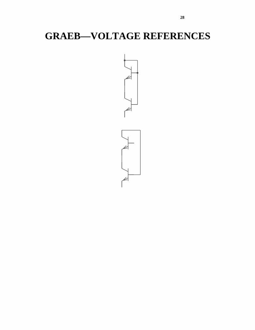
EXPLOITING GENERAL KNOWLEDGE —CONTINUED
• Make certain building blocks into primitive component-inserting functions • Graeb, Zizala, Eckmueller, and Antreich (2001) identified (for a purpose entirely unrelated to evolutionary computation) a promising set of frequently occurring combinations of transistors that are known to be useful in a broad range of analog circuits. • From their set involving 2 transistors, we have implemented circuit-constructing functions that insert a • current mirror • a loaded current mirror • 2 types of voltage references • a level shifter

27
GRAEB—CURRENT MIRROR
GRAEB—LOADED CURRENT MIRROR
28
GRAEB—VOLTAGE REFERENCES

29
GRAEB—LEVEL SHIFTER

30
EXPLOITING GENERAL KNOWLEDGE —CONTINUED
• Narrower (only 3 orders of magnitude) range of values for resistors and capacitors

31
EXPLOITING GENERAL KNOWLEDGE —CONTINUED
• Current flow analysis (Sripramong and Toumazou 2002)

32
EXPLOITING PROBLEM-SPECIFIC KNOWLEDGE
• A differential pair that receives the inverting input and non-inverting input is a useful first stage in designing an amplifier with the characteristics of the LM124.
• 2 ways to implement • Hard-wired into the embryo • Hard-wired into the top of every program
tree (S-expression) and then immunizing these nodes from modification by the genetic operations

33
IMPROVED GP TECHNIQUES • We previously used VIA, PAIR_CONNECT, NODE functions. Now we have NODE_INCREASED_SCOPE function (along with VIA) • Three-argument Y division function • The two new resistors produced by a series or parallel division to be assigned values such that the new topological composition has the same overall behavior as the original single component (Trent McConaghy) • All inserted components (2-leaded and N-leaded) are now non-modifiable after insertion into the developing circuit (eliminating asymmetry that promises to get even worse with use of the Graeb components)

34
IMPROVED GP TECHNIQUES—CONTINUED
• Three-argument Y division function • The two new resistors produced by a series or parallel division to be assigned values such that the new topological composition has the same overall behavior as the original single component • All inserted components (2-leaded and N-leaded) are now non-modifiable after insertion into the developing circuit

35
GRAPPLING WITH A MULTI-OBJECTIVE FITNESS MEASURE
• The fitness measures used in previously published examples of the synthesis of analog circuits (evolvable hardware) by means of genetic programming (and genetic algorithms) typically consist of only a small handful of different elements—rarely as many as 4 • Previously published work typically employs only a single test fixture (test bench) to measure the circuit’s fitness.

36
LM124 PROJECT • 16 elements • 5 test fixtures

37
LM124 PROJECT—16 ELEMENTS (1) 10dB initial gain, (2) supply current, (3) offset voltage, (4) direction cosine, (5) gain ratio, (6) output swing, (7) output swing direction cosine, (8) variable load resistance signal output, (9) open loop gain for the non-inverting configuration, (10) 900 KHz unity gain bandwidth for the non-inverting configuration, (11) phase margin for the non-inverting configuration, (12) open loop gain for the inverting configuration, (13) 900 KHz unity gain bandwidth for the inverting configuration, (14) phase margin for the inverting configuration, (15) inversion enforcement across test fixtures for the inverting and non-inverting configurations, and (16) bias current.

38
TEST FIXTURE NO. 1—NON-INVERTING CONFIGURATION
VOUT
Inverting
CCS 2CCS 1
CCS 3
NonInverting
V
Embryo
Output
+15v
-15v
100F
C1
10uV
V11Hz
-+
Q2Q1
Q4Q3
R1
1Meg
• Open loop gain (in decibels) for the NON-INVERTING configuration • 900 KHz unity gain bandwidth for the NON-INVERTING configuration • Phase margin for the NON-INVERTING configuration

39
TEST FIXTURE NO. 2—INVERTING CONFIGURATION
VOUT
Inverting
CCS 21CCS
3CCS
NonInverting
V
Embryo
-15v
+15v
Output
R1
1Meg
1Hz
10uV
V1
-+
100F
C1
Q2Q1
Q4Q3
• This test fixture differs from first one in that the inverting and non-inverting inputs are switched • Open loop gain (in decibels) for the INVERTING configuration • 900 KHz unity gain bandwidth for the INVERTING configuration • Phase margin for the INVERTING configuration

40
TEST FIXTURE NO. 3—BIAS CURRENT
VOUT
Inverting
CCS 21CCS
3CCS
NonInverting
V
Embryo
Output
+15v
-15v
R1
1Meg
1Meg
R2
Q2Q1
Q4Q3
• This test fixture differs from first one only in that there is no signal source, that there is no capacitor, and that there is a 1 mega-Ohm resistor between ground and the inverting input.
41
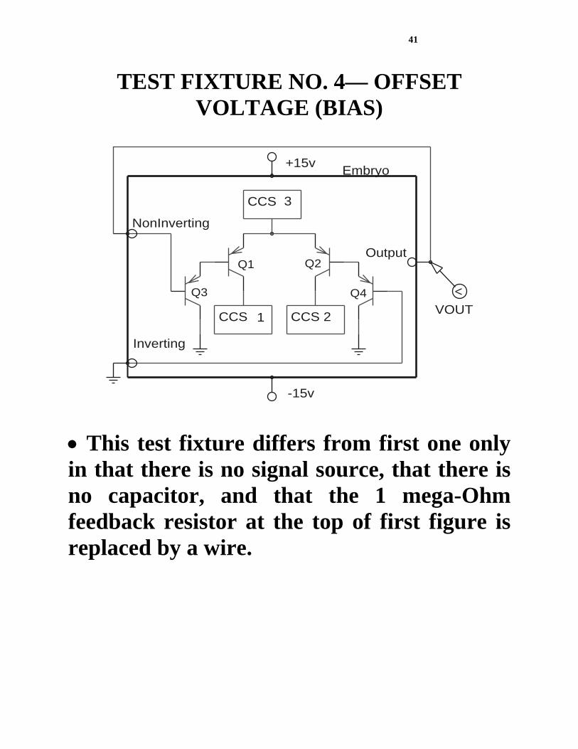
TEST FIXTURE NO. 4— OFFSET VOLTAGE (BIAS)
Inverting
CCS 21CCS
3CCS
NonInverting
VOUT
V
Embryo
Output
+15v
-15v
Q2Q1
Q4Q3
• This test fixture differs from first one only in that there is no signal source, that there is no capacitor, and that the 1 mega-Ohm feedback resistor at the top of first figure is replaced by a wire.

42
TEST FIXTURE NO. 5—FOUR PROBE POINTS, SEVEN MEASUREMENTS, AND
HARD-WIRED CALCULATIONS
VOUT
INTEG1MULT1
VTARGETGAIN
VGAIN
MINUS1
GAIN1 INTEG3
MULT4VDIFFERENTIALGAIN
MULT3
INTEG2SQRT2
VGAINRATIO
A
B
DIVV
DIVV2
VDIRECTIONCOSINEDIVV1
B
ADIVV
MULT2
SQRT1
Inverting
NonInverting
VOFFSET
CCS 2CCS 1
CCS 3
V
V
V
V
V
V
V
Embryo
Output
+15v
-15v
1F
C2
10k
R2
1E3
3HzV2
10uV
-+
SQRT
SQRT
R1
100k
Q1 Q2
Q4Q3100F
C1
10uV
V15Hz
-+
• the initial 10dB amplification • output voltage under different loads (corners) • direction cosine • the gain ratio • the offset voltage • the output swing • the output swing direction cosine

43
GRAPPLING WITH A MULTI-OBJECTIVE FITNESS MEASURE
• The goal to conduct an automated search (without human interaction) when one does not have any detailed information about the interrelationships among the various elements of the fitness measure

44
GRAPPLING WITH A MULTI-OBJECTIVE FITNESS MEASURE—
CONTINUED • Even in such situations, one usually knows a little. • A little information can go a long way toward constructing a serviceable fitness measure that can navigate a complex search space in a surprisingly effective way.

45
GRAPPLING WITH A MULTI-OBJECTIVE FITNESS MEASURE—
CONTINUED • One thing that is almost always known is the identity of the preeminent element of the fitness measure. • Acknowledging the special role of a preeminent element of the fitness measure and disproportionately rewarding the attainment of a certain modest threshold level for that element may avoid some alluring sub-optimal basins of attractions. • By heavily rewarding circuits that deliver as little as 10 dB of gain, one can direct the search away from the large and alluring subspace of totally degenerate circuits that deliver no gain at all (e.g., single wires) but that achieve non-zero scores for secondary elements of the fitness measure (e.g., freedom from bias and distortion).

46
GRAPPLING WITH A MULTI-OBJECTIVE FITNESS MEASURE—
CONTINUED • Identify all the elements of the fitness measure for which there is no practical advantage to any improvement once some minimal level of performance has been achieved. • As soon as the required minimal level is achieved for these elements, the detrimental contribution to fitness from that element should be defined to be 0 and no subsequent reward given for additional improvement.
• Eliminates the potentially distracting effects of already satisfied elements of the fitness measure • Relieves the human user of the need to arbitrarily pre-specify a tradeoff between disparate elements of the fitness measure

47
THE 16 ELEMENTS ORGANIZED INTO 4 GROUPS
Preeminent element
Amplifier-like behavior
Achievement of one required value
Time-domain signal matching
• 10dB initial gain
• Phase margin (inverting) • Phase margin (non-inverting) • Unity gain bandwidth (inverting) • Phase and amplitude inversion • Unity gain bandwidth (non-inverting)
• Desired Decibel gain (inverting) • Desired decibel gain (non-inverting) • Output swing • Offset voltage • Bias current • Variable load performance • Supply current
• Direction cosine • Gain ratio • Output swing direction cosine
48
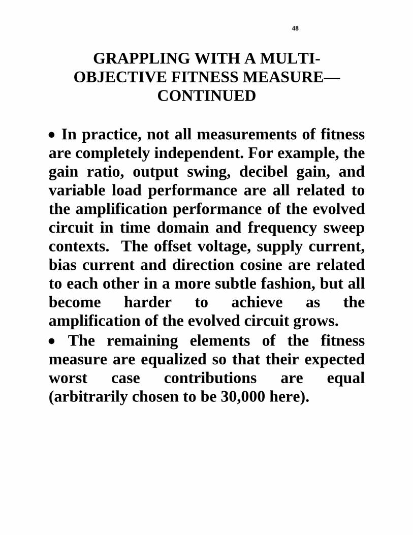
GRAPPLING WITH A MULTI-OBJECTIVE FITNESS MEASURE—
CONTINUED • In practice, not all measurements of fitness are completely independent. For example, the gain ratio, output swing, decibel gain, and variable load performance are all related to the amplification performance of the evolved circuit in time domain and frequency sweep contexts. The offset voltage, supply current, bias current and direction cosine are related to each other in a more subtle fashion, but all become harder to achieve as the amplification of the evolved circuit grows. • The remaining elements of the fitness measure are equalized so that their expected worst case contributions are equal (arbitrarily chosen to be 30,000 here).

49
PROGRESSIVE CHANGE AMONG 8 SELECTED ELEMENTS OF THE
FITNESS MEASURE
0
100000
200000
0 1 4 8 10 16 17 19 22 27 29 35 44 52 60 63 74 82 92 104 113 120Generation
Fitn
ess
Bias CurrentVariable Load ResistanceOutput SwingOutput Swing Direction CosineSupply CurrentOffset VoltageGain RatioDirection Cosine

50
4 OBSERVED PHASES IN RECENT RUNS—40 DB AMPLFIER PROBLEM
(1) initial topology search (2) formation of a core topology (3) component solution (4) refinement

51
PHASE 1 • For 40 DB, phase 1 is done by generation 1 and establishes initial topologies that deliver at least 10 dB of gain and that exhibit amplifier-like behavior (i.e., the elements of the fitness measure in columns 1 and 2)

52
BEST-OF-RUN CIRCUIT OF GENERATION 120
V+
V-
Output
NonInverting Inverting
R1
521
3.27Meg
R3
Q9
R2 1.77Meg
Q16
1G
1G
1k
1G
1G
Q22
1GQ8
Q7
I4 951uA
-+
Q2
49.7uA
I2
- +
Q10
D2Q6
D1
I3
60.9uA
- +
13.7pAI5
-+
I1
1.37mA
- +
Q5
Q21
Q12
Q13
Q3
Q14
Q17 Q15
Q18
Q20
Q19
D3
Q4Q1

53
PHASE 2 • Phase 2 searches for a core topology. In generation 17, a core topology emerges that links the differential pair (Q1–Q4), a transistor (Q5), a resistor (R1), the positive power supply (V+), and the output. • This topology persists for the remainder of the run. • During this phase, the magnitude of each of the remaining elements of the fitness measure is substantially reduced. Although none of these elements are actually driven to 0, this phase establishes a baseline value for each of these elements for the next phase.
54
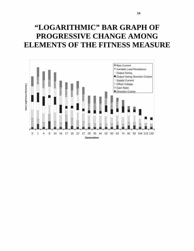
“LOGARITHMIC” BAR GRAPH OF PROGRESSIVE CHANGE AMONG
ELEMENTS OF THE FITNESS MEASURE
0 1 4 8 10 16 17 19 22 27 29 35 44 52 60 63 74 82 92 104 113 120Generation
Sum
[ lo
g(Fi
tnes
s El
emen
t) ]
Bias CurrentVariable Load ResistanceOutput SwingOutput Swing Direction CosineSupply CurrentOffset VoltageGain RatioDirection Cosine

55
PHASE 3 • There are 3 sub-phases in which the run concentrates on one, two, or three elements of the six elements of the fitness measure shown in the third column.
• 1st sub-phase of phase 3: Between generations 18 and 29, a current mirror is added to the circuit to help drive the gain ratio and output swing to 0. (This then disappears). • 2nd sub-phase of phase 3: Between generation 30 and 73, the run concentrates on offset voltage, bias current, and variable load performance (i.e., the “corners” of the load envelope). The variable load performance becomes satisfied with the addition of the current source I1 to the core topology.

56
PHASE 3—CONTINUED • 3rd sub-phase of phase 3: Between generation 74 and 113), the offset voltage and bias currents become satisfied. In generation 104 the bias currents are pulled below the specified values with the introduction of current source I4. Generation 113 sees the offset voltage satisfied by substitution of a previously placed transistor with a current mirror consisting of Q6 and Q7, completing what would be the core of the solution circuit.

57
PHASE 4 • In phase 4, the remaining residual error of
the fitness measure elements in the third column are pushed toward their ideal values

58
BEST-OF-RUN CIRCUIT OF GENERATION 120
V+
V-
Output
NonInverting Inverting
R1
521
3.27Meg
R3
Q9
R2 1.77Meg
Q16
1G
1G
1k
1G
1G
Q22
1GQ8
Q7
I4 951uA
-+
Q2
49.7uA
I2
- +
Q10
D2Q6
D1
I3
60.9uA
- +
13.7pAI5
-+
I1
1.37mA
- +
Q5
Q21
Q12
Q13
Q3
Q14
Q17 Q15
Q18
Q20
Q19
D3
Q4Q1

59
SUMMARY FOR GRAPPLING WITH 16-ELEMENT FITNESS MEASURE WITH 5
TEST FIXTURES
• Identify the preeminent element of the fitness measure and disproportionately reward the attainment of a modest threshold level for that element • Identify all the elements of the fitness measure for which there is no practical advantage to any improvement once some minimal level of performance has been achieved. • The remaining elements of the fitness measure are equalized so that their expected worst case contributions are equal (arbitrarily chosen to be 30,000 here).

60
OVERALL SUMMARY
• 4 ways for using general domain knowledge about circuits • 2 ways for employing problem-specific knowledge • 4 ways of improving on previously published GP techniques • 4 ways of grappling with multiobjective fitness measure