toward the development of an interactive modeling, simulation, animation, and real- time control...
TRANSCRIPT

Toward the Development of an Interactive Modeling, Simulation, Animation, and Real-Time Control (MoSART) Hardware/Software
Testbed for a Tilt-Wing Rotorcraft
John S. KoenigArizona State University, Tempe AZ
IEEE Student Member #40351269
IEEE Region 6, Southwest Area,
Student Paper Contest
San Diego, CA
Saturday March 27th, 1999
Introduction
• Motivation
• Contributions of Work
• Test Stand Pitch Dynamics
• Controller Design
• MoSART Environment
• Utility of Environment
• Summary and Future Work

Motivation
• High Speed Autonomous Rotorcraft Vehicle (HARVee) Project at ASU – Tilt-wing aircraft which combines the benefits of a
helicopter and an airplane– NEED: Automatic control for safe hover flight

Motivation
• Hardware Test Stand– Lab-scale test bed for control system development– NEED: Mathematical modeling, simulation, and
real-time control

• Nonlinear and linear model development
– 1 DOF Test Stand Pitch Dynamics
• Linear controller design
• Tilt-Wing Software Environment
– Open-loop and closed-loop simulation
• Modeling, Simulation, Animation, and Real-Time Control
(MoSART)
– Interactive tool for control system design
– Can be connected to hardware to form integrated
hardware/software testbed
Contributions of Work

Test Stand Description
• Four degrees-of-freedom
• Replicates all hover mode control inputs
(except has only two main engines)
• Fully constrained and contained
Modeling
• Second order, non-linear model
– 1 DOF pitch dynamics
– Three Point-Mass Representation

Three Point-Mass Model
Non-linear model:
32321 x1x2
yx3x2x1
y321
y
z dTdTI
1cosdmdmdm
I
gsinmmm
I
gd
Where,
17
1i
2z
2xiy ddmI
i

Incorporate known parameters:
1T4.1425
25s
4.14)s(P
2
Linearize (sin, for small angles):
Determine transfer function:
1T4.14sin25
Model Development

Open-Loop Stability
• Plant Transfer function:
• Root Locus Plot:
Open-Loop Poles
at s=±5
)5)(5(
4.14
25
4.14)(
2
ssssP
-5 +5
imaginary
real
unstable
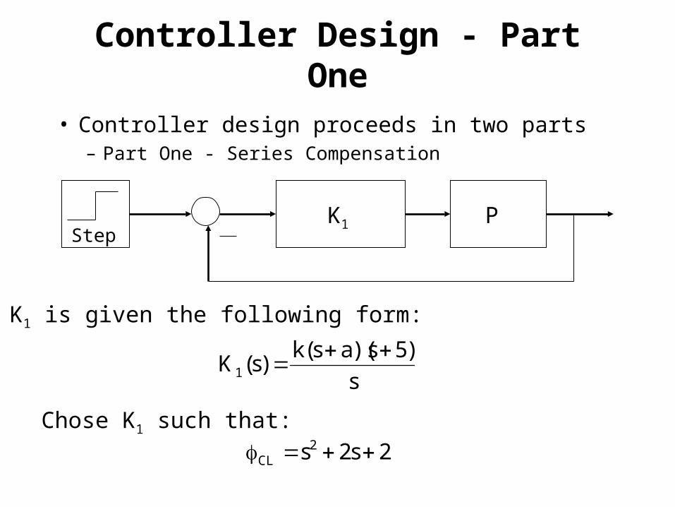
Controller Design - Part One
• Controller design proceeds in two parts– Part One - Series Compensation
PStep
K1
Chose K1 such that:2s2s2
CL
K1 is given the following form:
s
)5s)(as(k)s(K1

Controller Design - Part One
0
2
0 2 4 6
Time
Pit
ch
An
gle
2s2s)as(k4.14)5s(s 2CL
486.0k
25k4.14
286.0a
2a)486.0(4.14
2ka4.14
2s2ska4.14s)5k4.14(s 22CL

Controller Design
s largefor , kss
)5s)(as(k
Closed-loop transfer function has the form:
kas)1k(s
)as(kTF
2CL
Derivative action [(s+a) term] produces large magnitude response to a high-frequency input.
Controller output when s is very large:

Eliminate overshoot by employing a feed-forward loop.
Step 25s
4.142
s
)5s)(as(k
ks
ks)s(K2
0
2
0 2 4 6
Time
Pit
ch A
ng
le
Controller Design - Part Two

K1(s) and K2(s) are improper and the following modificationsare made to make them strictly proper:
2
1 50s
50
s
)5s)(as(k)s(K
2
2 50s
50ks)s(K
Closed-loop transfer function now takes the form:
kas)1k(s
kaTF
2CL
Controller Design

MoSART Environment
• System specific, interactive software
environment for Modeling, Simulation,
Animation, and Real-Time Control (MoSART)
• Runs on Pentium PC platform under
Windows 95/NT
• Written in C++, using Microsoft Foundation
Classes (MFC) and Direct-3D
• Utilizes MATLAB for analysis purposes

MoSART Environment
• Environment structured around four modules:
– Program Interface Module (PIM)– Simulation Module (SIM)– Graphical Animation Module (GAM)– Help-Instruct Module (HIM)
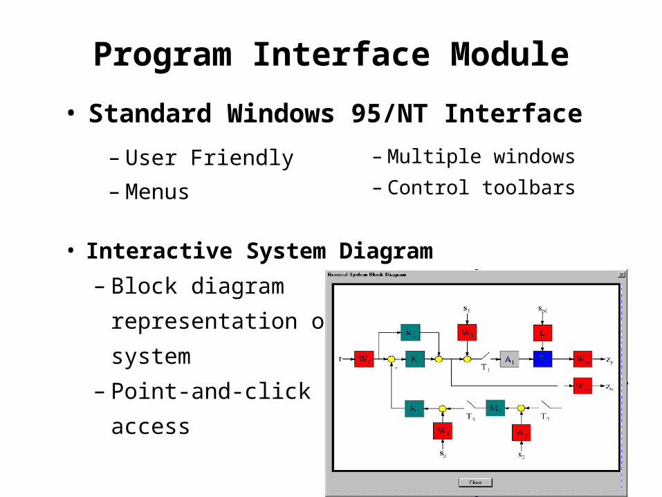
Program Interface Module
• Interactive System Diagram
– Block diagram
representation of
system
– Point-and-click
access
• Standard Windows 95/NT Interface
– User Friendly
– Menus
– Multiple windows
– Control toolbars

Simulation Module
• Numerical Simulation– Fast compiled C++– Faster than real-time simulation is possible
• On-the-fly Parameter Editing– Change model– Edit controller parameters– Adjust reference commands (step, sinusoid, etc.)– Different integration methods (Euler, 4th order
Runge-Kutta)
• Dynamic linking to MATLAB engine

Graphical Animation Module
• 3-D Animation (Direct-3D)– Texture-mapped, light-shaded polygons
• Visualization Tools– Real-time 3-D and graphing windows

Help-Instruct Module
• On-line Help– Instructions on using the environment
• HTML/PDF Documents– Model documentation/references– On-line tutorials

Utility of Environment
• Open-loop simulation– 3-D visualization of unstable system– Change between linear and non-linear models
– Utilize MATLAB for data analysis and comparison

Utility of Environment
• Controller Design - Series and Feed-Forward– Animation
• Visualize positive and negative aspects of a design– Series controller = large overshoot (negative)
– Series+feed-forward = small overshoot (positive)
– Graphing Windows• Real-time plotting of user-specified parameters
– Pitch angle vs. time
• Utilize MATLAB engine for analysis– Such as comparing the linear and nonlinear responses

Utility of Environment
• Controller Design - High vs. Low Gain
– MATLAB processing of data gives precise measure of linear error
0
0.01
0.02
0.03
0.04
0.05
0.06
0.07
0 1 2 3 4 5 6 7
Time (sec)
Err
or
(deg
rees
)
– (k) and (a) values adjusted with with point-and-click interface
– Effects of controller changes can be seen in seconds

Future Work
• Link hardware test stand with MoSART environment– Hardware/software testbed will be an effective
control system design tool– Provides real-time control of actual hardware
• Mathematical model development– 4 DOF test stand dynamics– 6 DOF tilt-wing rotorcraft dynamics

Summary
• Linear and nonlinear models developed
– 1 DOF pitching dynamics
• Linear controller developed
– Tested using linear and nonlinear models
• MoSART software environment
– Simulation, Animation, Analysis, Control
– Interactive tool for controller design