towards designing high aspect ratio high … · • introduce hale-uav • a vision of future –...
TRANSCRIPT

Nov 2002, Presentation UAV Workshop, Bath University
TOWARDS DESIGNING HIGH ASPECT RATIOHIGH ALTITUDE JOINED-WING SENSOR-
CRAFT (HALE-UAV)
Dr. R. K. NangiaBsc PhD CEng AFAIAA FRAeS
Nangia Aero Research Associates,BRISTOL, UK.
Copyright c: Nangia 2002, Published by University of Bath with permission

Report Documentation Page Form ApprovedOMB No. 0704-0188
Public reporting burden for the collection of information is estimated to average 1 hour per response, including the time for reviewing instructions, searching existing data sources, gathering andmaintaining the data needed, and completing and reviewing the collection of information. Send comments regarding this burden estimate or any other aspect of this collection of information,including suggestions for reducing this burden, to Washington Headquarters Services, Directorate for Information Operations and Reports, 1215 Jefferson Davis Highway, Suite 1204, ArlingtonVA 22202-4302. Respondents should be aware that notwithstanding any other provision of law, no person shall be subject to a penalty for failing to comply with a collection of information if itdoes not display a currently valid OMB control number.
1. REPORT DATE 26 JUL 2004
2. REPORT TYPE N/A
3. DATES COVERED -
4. TITLE AND SUBTITLE Towards Designing High Aspect Ratio High Altitude Joined-WingSensorcraft (HALE-UAV)
5a. CONTRACT NUMBER
5b. GRANT NUMBER
5c. PROGRAM ELEMENT NUMBER
6. AUTHOR(S) 5d. PROJECT NUMBER
5e. TASK NUMBER
5f. WORK UNIT NUMBER
7. PERFORMING ORGANIZATION NAME(S) AND ADDRESS(ES) Nangia Aero Research Associates, BRISTOL, UK.
8. PERFORMING ORGANIZATIONREPORT NUMBER
9. SPONSORING/MONITORING AGENCY NAME(S) AND ADDRESS(ES) 10. SPONSOR/MONITOR’S ACRONYM(S)
11. SPONSOR/MONITOR’S REPORT NUMBER(S)
12. DISTRIBUTION/AVAILABILITY STATEMENT Approved for public release, distribution unlimited
13. SUPPLEMENTARY NOTES See also ADM001685, CSP 02-5078, Proceedings for Aerodynamic Issues of Unmanned Air Vehicles(UAV)., The original document contains color images.
14. ABSTRACT
15. SUBJECT TERMS
16. SECURITY CLASSIFICATION OF: 17. LIMITATION OF ABSTRACT
UU
18. NUMBEROF PAGES
66
19a. NAME OFRESPONSIBLE PERSON
a. REPORT unclassified
b. ABSTRACT unclassified
c. THIS PAGE unclassified
Standard Form 298 (Rev. 8-98) Prescribed by ANSI Std Z39-18

ACKNOWLEDGEMENTS
• The work is part of in-house R & D activities and alsosupported in part by the USAF-EOARD.
• The authors have pleasure in acknowledging helpfultechnical discussions with Dr. D. Multhopp, Dr CarlTilmann, Dr. C. Jobe, Dr. W. Blake (all from US-AFRL), Dr. M. E. Palmer.
• Lastly, any opinions expressed are those of theauthor.

This Presentation• Introduce HALE-UAV• A Vision of Future – Sensor Craft Importance• Joined-Wing Configs.• 2-D Laminar Aerofoils• Aspects of 3-D Design, different Swept Tips• LE Suction Control, Elliptic loadings, Neutral Stab.• CFD Checks• Inverse 3-D Design Capabilities• Intake Design – Preliminary Work• Avenues for Further Work

Typical HALE Global Hawk
span: 116 ft, length 44 ftlight composites, aluminium fuselage, COST $10M
Range 12000 nm, AUW 25,600 lb , range up to 2000nm at 65000ft
flies to an area 1200 miles and remains on station 24 hrs
cloud penetrating synthetic aperture radar /ground moving target indicator, electro-optical and infra-red sensors
image an area 40,000 square miles (State of Illinois) in 24 hours

WOLKOVITCH


extrapolate

Guess !

Goodefficiency !


TANKERS TRANSPORTS

SENSOR-CRAFT WORLD


Other joined-wing possibilities

3000 nm
Loiter 40-80 hr 65 k ft
3000 nm
Loiter1 hr @ SL
ù ù ù
ù ùù
ù1
ù2 3
4
5
6
78
910
WTO
Mission profile and requirements
Mission Segments
1. Engine Start & Warm-up2. Taxi3. Takeoff4. Climb & Accelerate to Cruise5. Cruise out 30006. Loiter7. Return Cruise8. Descend 9. Loiter at Sea Level 10. Landing, Taxi, Shutdown
W/S range of interest: 30 - 60
T/W range of interest: .30 -.50
Cruise Radius: 3000 nm
Loiter: 65 Kft for 40 - 80 hr (at 3000 nm range)
Payload: 4000 lb Field Length: 5350 ft over 50 ft Obstacle (SLS)
Control: 20 kt cross-wind on takeoff and landing
Flight duration 4-6 daysImplies a Wide Flight Envelope

ht
0
10000
20000
30000
40000
50000
60000
70000
0 10000 20000 30000 40000 50000 60000 70000 80000
ht
Altitude - ft
Weight - lb
Mach 0.6,CL=1.59
Re=0.4 mil/ft
Mach 0.6,
CL=0.88
Re=0.35mil/ft
Mach 0.2
CL=0.95
Re=1.4mil/ft
Mach 0.15
CL=0.7
Re=1.1mil/ft LAND TAKE-OFF
CRUISE

CL
0
0.2
0.4
0.6
0.8
1
1.2
1.4
1.6
1.8
0 0.1 0.2 0.3 0.4 0.5 0.6 0.7
CL
CRUISE,
Re=0.44mil/ft
CRUISE,
Re=0.35mil/ftLANDING
Re=1.1mil/ft
TAKE-OFF
Re=1.4mil/ft
Mach no
CLL

X - Band Antenna
Reference Configuration - Antenna Integration
Design Driver: Aero-Performance of Very Thick Airfoils
2-D DriverHigh t/cHigh L/DLaminar Flow 50%cCritical Mach at cruiseLow Re
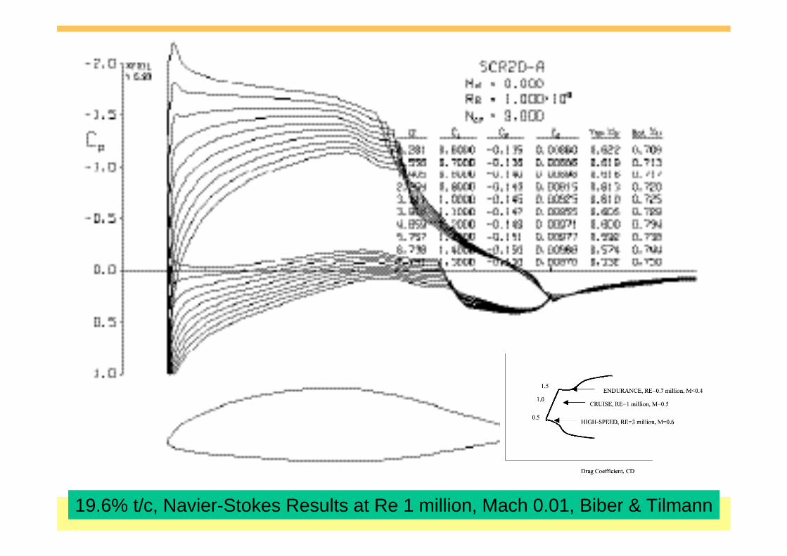
19.6% t/c, Navier-Stokes Results at Re 1 million, Mach 0.01, Biber & Tilmann

2-D CALCULATIONS, INVISCID, MACH no VARIES from 0.0 to 0.6
t/c 16% uncambered
t/c 16% cambered

t/c 19.6% uncambered
t/c 19.6% cambered
2-D CALCULATIONS, INVISCID, MACH no VARIES from 0.0 to 0.6

SUMMARISING THE AEROFOIL PERFORMANCE, LAMINAR FLOW CAPABILITY Uncambered & Cambered
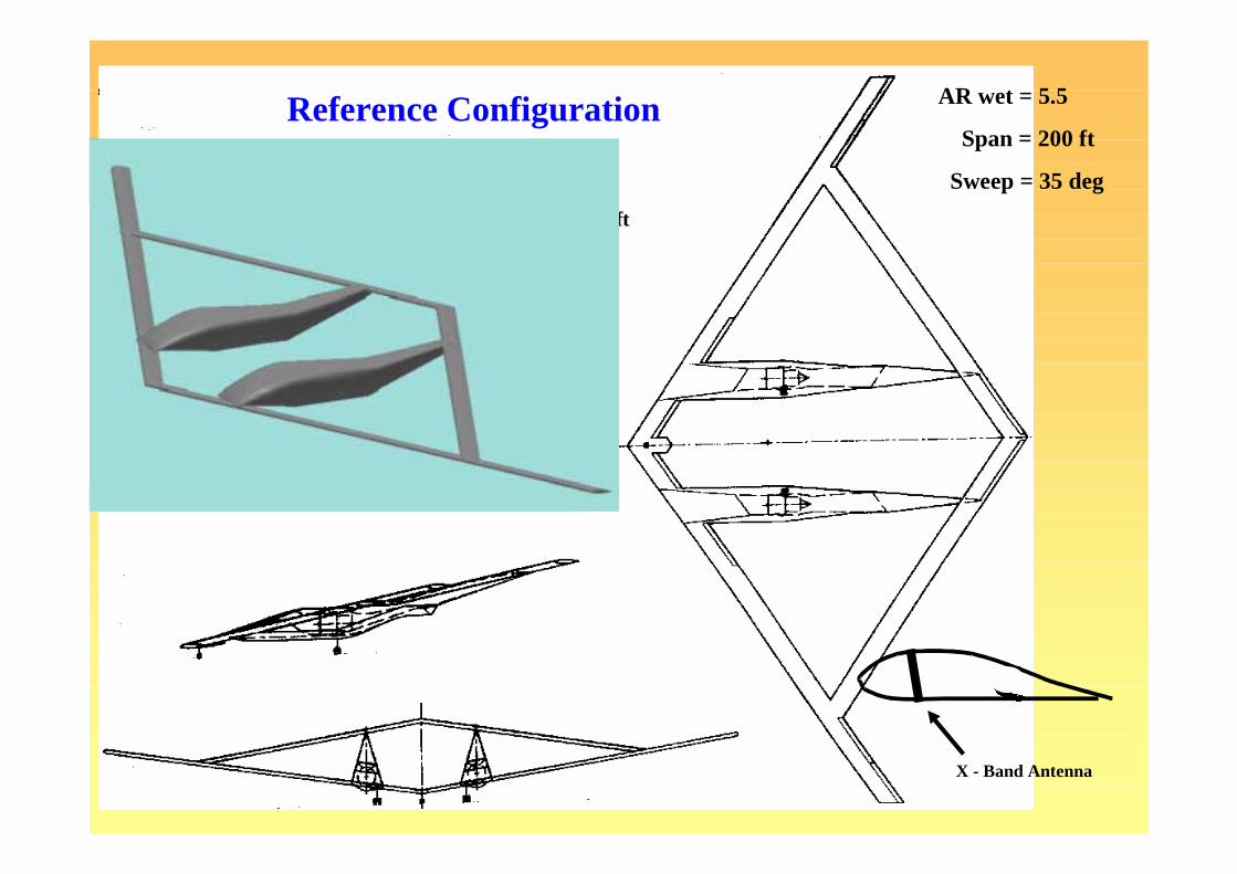
X - Band Antenna
Sized Geometry
(From W/S = 30) Wing Area (Gross): 2300 sq ft
(From Antenna) Aspect Ratio (Gross): 17.4
AR wet = 5.5
Span = 200 ft
Sweep = 35 deg
Reference Configuration

AT1 FT2FT1
Identical frontalview
notenote
JOINED WING CONFIGURATIONS

Aerofoil Shapes
AT! CONFIGURATION

AT!, BASIC CHARACTERISTICS, Uncambered AerofoilsCp Distributions & Interference Effects On Spanwise Loadings

DESIGNED WING,Super-Critical Type Aerofoil,Twist & camber
Assume Zero Static Margin (Neutral Stability)Respective Wing Settings Follow, Use Panel Method

Spanwise Loadings AoA = 3.25, 4.25, 5.25

Cp Distbns.
AoA = 3.25, 4.25, 5.25

Design AoA + 0 deg Design AoA + 1 deg
EULER CFD CHECKDesigned Case & Off-Design look for extreme gradients

Design AoA + 3 deg Design AoA + 4 deg
NOTENOTE

Panel, CL = 0.59 Euler,CL = 0.51

Euler, M=0.6, Design AoA + 0 deg, CL = 0.51, Upper Surface
Mach no

Mach no.
Euler, M=0.6, Design AoA + 4 deg, CL = 1.08, Upper Surface

POWERFUL INVERSE METHOD, KNOWN Target Pressure Distbn.“Supplanted” on a GIVEN WING
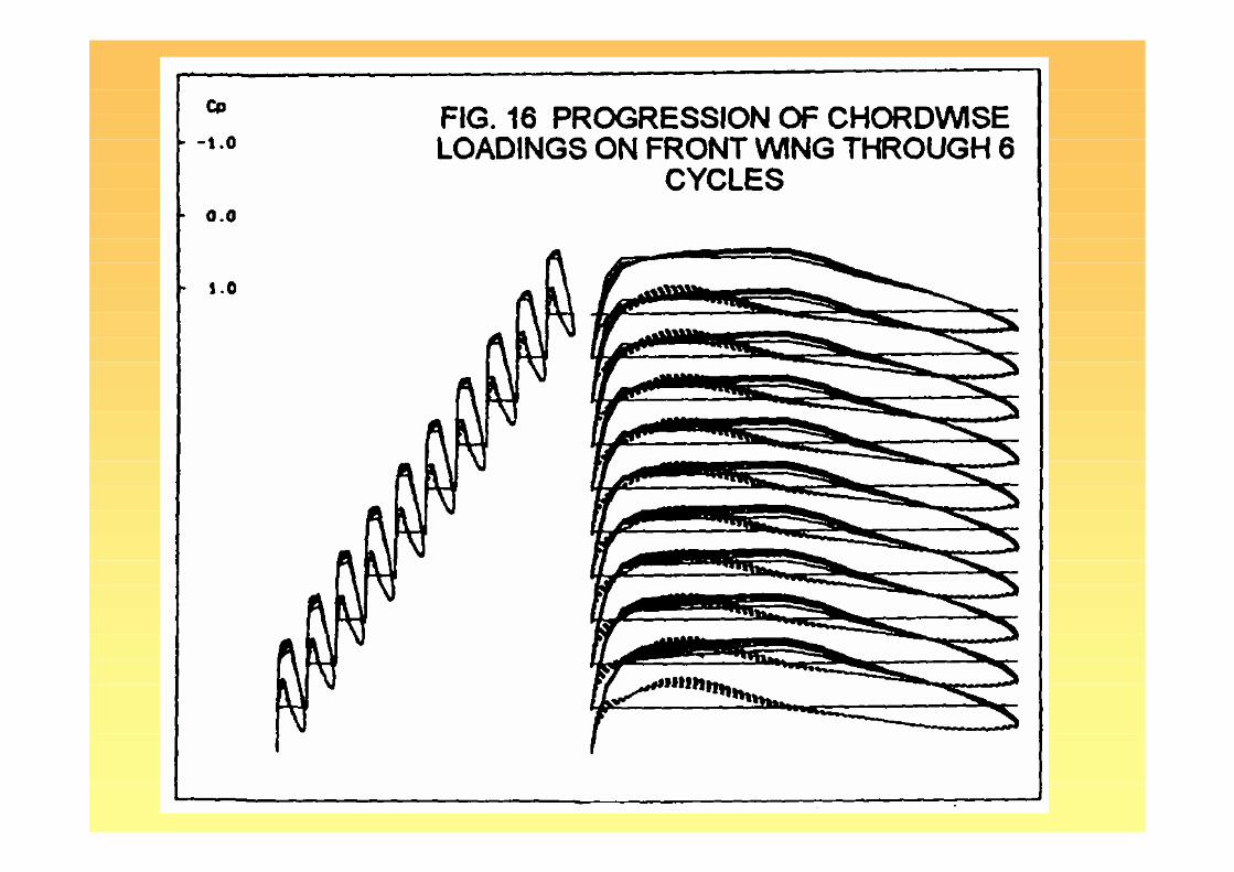


COMPARING AEROFOIL SECTIONS ON FRONT WING AT START & AFTER 6CYCLES (WING AND TAIL BOTH MODELLED)

Laminar AT1

CL & CmReference &Control due to 0.5deg setting angle changes
reference

SPANWISE LOADINGS AT Mach 0.6, CL=0.72, 0.9,1.07,1.25.1.43,1.6
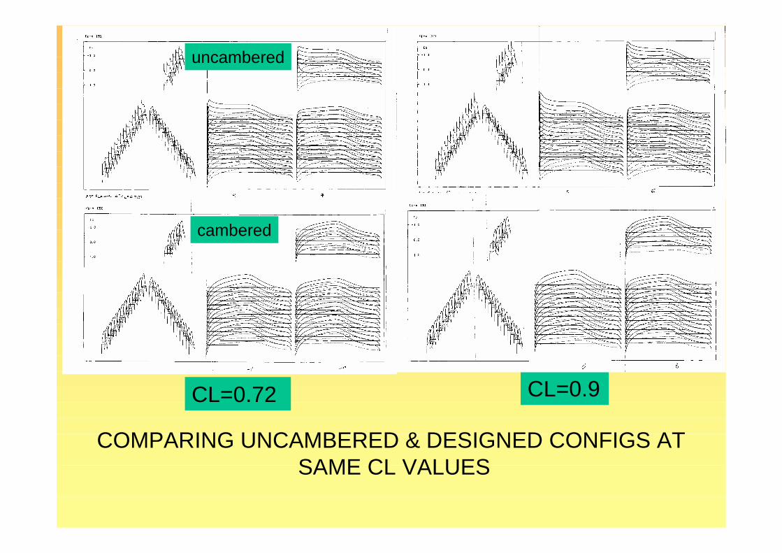
COMPARING UNCAMBERED & DESIGNED CONFIGS AT SAME CL VALUES
CL=0.9
uncambered
cambered
CL=0.72

COMPARING UNCAMBERED & DESIGNED CONFIGS AT SAME CL VALUES
CL=1.07 CL=1.25
uncambered
cambered

COMPARING UNCAMBERED & DESIGNED CONFIGS AT SAME CL VALUES
CL=1.43 CL=1.6
uncambered
cambered
Possibly Exceeding Laminar limits at Wing Junction
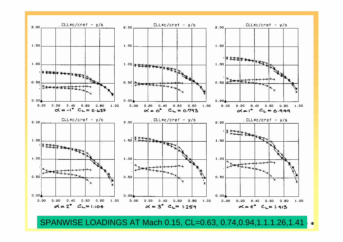
SPANWISE LOADINGS AT Mach 0.15, CL=0.63, 0.74,0.94,1.1.1.26,1.41

Cp Distbns. AT Mach 0.15, CL=0.63, 0.74,0.94,1.1.1.26,1.41

Forward Swept Tip FT1 Laminar

SPANWISE LOADINGS AT Mach 0.6, CL=0.72, 0.9,1.07,1.24.1.43,1.6

COMPARING UNCAMBERED & DESIGNED CONFIGS AT SAME CL VALUES
CL=0.9 CL=1.07
COMPARING UNCAMBERED & DESIGNED CONFIGS AT SAME CL VALUES
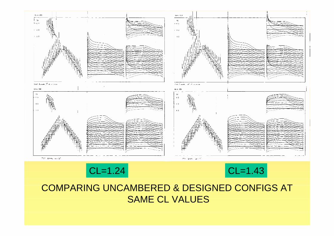
CL=1.24 CL=1.43

COMPARING UNCAMBERED & DESIGNED CONFIGS AT SAME CL VALUES
CL=1.6
Possibly Exceeding Laminar limits at Wing Junction

Twin Fuselage intakes
Propulsion Considerations

Central Fuselage intake
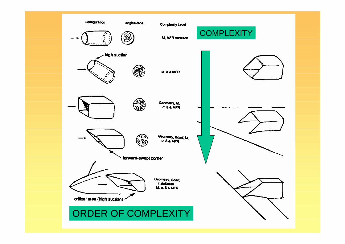
COMPLEXITY
ORDER OF COMPLEXITY

UNSCARFED INTAKES
Increasing MFR

UNSCRAFED, SCARFED & 3-D STEALTHY INTAKES
0 alpha
High alpha

Zero speed

Central Intake Integration& Modelling
magnified

Cp
ML
Central, MEF=0.6, M=0.5

Contraction Ratio CR
Mach No

Intakes, Propulsion
• Shown a Preliminary set of Results• Sizing is the first Concern• Altitude of Operation !• Off-Design• Suitable Power-plants !• Possibly Two needed• Work Continues ……• Experimental Work needed

Configuration & Structure
• Configuration / Layout• What Light Materials• One or two Fuselage• Are such high AR craft feasible, structure• Aero-elastic tailoring• Manufacturing Constraints
Aerodynamics / Flow Control /Control
• Viscous Effects: Laminar Flow Extent• Spanwise press. gradients• Effect of Sweep, lower sweep Config. !• Field performance• Off-design, side-slip• Controls location, pitch, directional & lateral• Off-design• Flow control, what & where!

Experimental work
• Difficulty in modelling large AR Configs• Reynolds Number Considerations• Laminar flow in WT !• Half models• Control effects not representative of full-scale• A Radio Control Free-Flight Model !• Propulsion Integration Considerations

Concluding Remarks• Introduced HALE - UAV• A Vision of Future – Sensor Craft Importance• Joined-Wing Configs.• 2-D Laminar Aerofoils• Different Type of Swept-Tips in 3-D• Aspects of 3-D Design• LE Suction Control, Elliptic loadings, Neutral Stab.• CFD Checks – Forward-Swept Root area• Inverse Design Capabilities• Intake Design – Preliminary Work• Avenues for Further Work

*** Thank You for Listening ***
So I hope, enough has been shown tointerest and inform you in the fast
moving field of Sensor-CraftPLENTY of Further Work!
************Shall we try Comments and Questions?