towards low mass and low inertia dynamic balancing …
TRANSCRIPT

TOWARDS LOW MASS AND LOW INERTIADYNAMIC BALANCING OF MECHANISMS
-DYNAMIC BALANCING BY USING COUNTER-ROTARY
COUNTER-MASSES
m* I*
O
k
m I
l*
l
q
Design Space& Work Space
CRCM
V. van der Wijk-
DELFT UNIVERSITY OF TECHNOLOGY - 2008

TOWARDS LOW MASS AND LOW INERTIADYNAMIC BALANCING OF MECHANISMS
-DYNAMIC BALANCING BY USING COUNTER-ROTARY
COUNTER-MASSES
V. van der Wijk
April 2008
Master Thesis 1110Student number 1045865
Examination Committee:
Prof. Dr. F.C.T van der Helm, BMechE, 3MEDr. ir. J.L. Herder, BMechE, 3MEDr. ir. A.L. Schwab, PME Engineering Dynamics, 3MEDr. ir. B. Demeulenaere, PMA, KU Leuven

PREFACE
After a period of dedicated and pleasant work, this master-thesis is the result of my research onlow mass and low inertia dynamic balancing of mechanisms.
It all started in September 2006. In the office of my supervisor Just Herder, filled with a wide va-riety of interesting mechanisms and Anglepoise lights, he showed me two lego-models of a counter-rotary counter-mass balancer. A rotatable link with a counter-mass for the force balance and gearsto have this counter-mass counter-rotate with respect to the link, made of lego. It looked impressiveand I believed him right away; it works but I do not understand how.
In October 2006 I moved to Aachen, Germany, were I would learn something about kinematicsat the Rheinisch-Westfalische Technische Hochschule. I worked for two months at the ’Institut furGetriebe und Machinendynamik’ of Prof. Burkhard Corves. Together with my supervisor JohannesKloppenburg and other colleagues it has been an interesting period. Much of my time I spent withthe beautiful and extended collection of mechanism models and in the small institute library withgreat (historical) books on kinematics.
At the end of November I moved from Aachen to Leuven, Belgium. At the department of’Werktuigkunde’ of the KU-Leuven I started with the research on low mass and low inertia dynamicbalancing. My supervisor Bram Demeulenaere has a wide experience in the field of dynamic bal-ancing and in addition, with running. Together with, head of the department, Prof. Joris de Schutter,Myriam Verschuure, Friedl De Groote and others, we made many runs across ’Den Dikke Bertha’.Inspirational runs and a prove of healthy science!
Back at the TU-Delft at the beginning of March 2007 the research came to rest, which wasbecause of the last master-courses I still had to finish. Around June the research could continueagain, resulting into this thesis now.
I would like to thank everyone that has been helpful with the research for this thesis. In special Iwould like to thank my supervisor Just Herder for all discussions, the writing support and reviewingthis thesis, Bram Demeulenaere for sharing the knowledge and experience on dynamic balancingand both Myriam Verschuure and Gert Kragten for their critical comments and advice.
Kinematics and Dynamics, Enjoy!
Volkert van der Wijk
April 2008
i

CONTENTS
Preface i
1. Introduction 2
2. Comparison of Various Dynamic Balancing Principles Regarding 6Additional Mass and Additional Inertia
3. Comparative Analysis and Optimization for Low-Mass and Low-Inertia Dynamic 19Balancing of a 1-dof Rotatable Link Balanced by a Counter-Rotary Counter-Mass
4. Double Pendulum Balanced by Counter-Rotary Counter-Masses as 30Useful Element for Synthesis of Dynamically Balanced Mechanisms
5. Complete Dynamic Balancing of Crank-Slider Mechanisms Without Additional 42Elements at the Coupler Link for Low-Mass and Low-Inertia Dynamic Balancing
6. Dynamic Balancing of Mechanisms by Using an Actively Driven 58Counter-Rotary Counter-Mass for Low Mass and Low Inertia
7. Discussion 71
8. Conclusion 78
Appendices
A. Effect of Belt Elasticity on the Dynamic Balance of a 81Counter-Rotary Counter-Mass Balancer
B. Calculations of the Transmission Ratio for Three Configurations 104of a 1-DOF Rotatable Counter-Rotary Counter-Mass Balanced Link
1

CHAPTER 1-
INTRODUCTION
2

INTRODUCTION
1The development of machines and mechanisms in early history evolved from the pressureof necessity. The powers of man had become inadequate, especially for moving heavy masses.Machines therefore were thought of as constructions that were able to transform a force. About28 B.C., the military engineer Vitruvius defined a machine as ”a combination of timber fastenedtogether, chiefly efficacious in moving great weights.”
For ages, machines were studied with respect to their function, e.g. for raising water or formilling grain. Reuleaux in 1875 changed this view by defining a machine to consist of six basicmechanical components. These are (1) the crank, (2) the wheel, (3) the cam, (4) the screw, (5) ratch-ets (intermittent-motion devices), and (6) tension and compression organs (with one-way rigidity asbelts and chains). These elements can be used to built machines - and mechanisms - from.
The idea of modifying motion rather than just the construction of machinery came up in theearly eighteenth century by Leopold. He attempted to treat the mechanisms systematically by study-ing how components transform, for example, a circular motion into a ”back-and-forward motion.”During the eighteenth century major contributions to the study of mechanism motion were doneby Watt and Euler. Watt was dedicated to the synthesis of motion while Euler was concerned withmotion analysis. Euler recognized that the general problem of dynamics could be separated intokinematics and kinetics. The geometric motion could be treated apart from the forces that inducemotion.
Due to the industrialization that came up during the eighteenth century, mechanism researchwas growing quickly. Machines and mechanisms had to take over tasks of man increasingly, whichis a still continuing process nowadays. Besides the importance of multi-functionality, there wasand is a rising need for faster motion and more accurate motion. From cutters and presses thatmove between thirty and fifty revolutions per minute to industrial sewing machines with up to tenthousand revolutions per minute2. Nowadays in the semi-conductor industry, manipulators have toplace microchips on integrated circuits at a high production speed and with high accuracy.
These increasing requirements face an important difficulty, namely dynamic unbalance. Dy-namic unbalance is a major cause of machine vibrations. Due to their inertia, the accelerating (anddecelerating) machine elements produce reaction forces and reaction moments to the machine base.The resultant reaction force (shaking force) and the resulting reaction moment (shaking moment)influence the motion of the mechanism and that of other mechanisms that are connected to the samebase.
To reduce the influence of machine vibrations, often vibration isolation is applied. In the semi-conductor industry, manipulators are programmed to have rests in their motion to wait until vibra-tions have died out. Manipulators are also controlled to move with a prescribed velocity or to movealong a specific trajectory for which the vibrations are minimal. Reducing the machine vibrationsby changing the design (in particular the mass distribution), is called dynamic balancing.
Contrary to the other solutions, dynamic balancing has the aim to eliminate the source of thevibrations. By redistributing the mass of the mechanism elements, the addition of extra (counter-)masses and elements, the design of the machine is changed such that the shaking force and shakingmoment become smaller or vanish. A completely (dynamically) balanced mechanism is obtained if
3

the design of the mechanism is such that for any motion of the mechanism the shaking force andshaking moment are zero.
Dynamically balanced mechanisms therefore are advantageous to improve the accuracy andproduction speed. Dynamic balance is also important for mechanisms that float in free space such asaircraft and satellites, since dynamic unbalance influences the position and orientation and hindersthe control of these machines. However until now, dynamic balancing goes together with a consider-able, if not huge, increase of mass and inertia. Wu and Gosselin in 20053 were the first to completelydynamically balance a 6-DOF spatial mechanism. However, to balance a payload of only 50g, atleast 4.5kg had to be added which is a factor 90(!) more. Besides, balanced mechanisms quicklybecome large and more complex. This makes dynamic balancing unpractical in situations where lowmass is important such as in aerospace industry, and in cases where little space is available, such asin internal combustion engines.
The aim of this thesis is to dynamically balance various 1-, 2-, and 3-degree-of-freedom pla-nar and spatial, serial and parallel mechanisms, for which the addition of mass and the addition ofinertia is minimal. A second purpose is to formulate design guidelines for dynamic balancing ofmechanisms that have a minimum of additional mass and the minimum of additional inertia.
This thesis is limited to complete dynamic balancing. For practical reasons, the choice often ismade to balance mechanisms partially. For instance by balancing some important vibration frequen-cies, such as with a balance shaft in internal combustion engines, by applying a flywheel to levelout accelerations, or by changing the design of the mechanism such that the remaining vibrationsare acceptable. The vibration reduction with respect to the addition of mass, inertia and complexitythen is more effective. However, for machines of the future that need to run faster and with moreaccuracy then those nowadays, research on complete dynamic balancing is necessary.
In addition, this thesis is restricted to dynamic balancing of mechanisms for which the elementscan be regarded as rigid bodies. Although at high loads or high speeds the elastic effects can becomesignificant, the compliancy of mechanism elements is related to the elastic property of the materialwhile the mass and the inertia of mechanism elements depend on the material density.
Approach and Thesis OutlineThe two goals of this thesis reinforce each other. Existing balancing principles are evaluated and
compared first, and are judged with respect to their performance regarding the addition of mass andthe addition of inertia. From the performance of the balancing principles, guidelines for low massand low inertia are obtained. With these guidelines new advantageous configurations are found andby evaluating them, new additional guidelines for low mass and low inertia dynamic balancing aredetermined.
Although it is known that existing principles to dynamically balance mechanisms increase themass and the inertia of the mechanism considerably, it is not known yet which of them leads to theleast addition of mass and inertia. Therefore a comparison, as fair as possible, of balancing principlesis done in chapter 2. The balancing principles are evaluated by using them to balance a doublependulum, which is found to be an important building element in the synthesis of mechanisms. TheMass-Inertia (MI) factor is proposed to judge the performance of the balancing principles regardingthe addition of mass and inertia and the balancing principles are classified.
With dynamic balancing there are various parameters that influence the addition of mass andthe addition of inertia, but how is unclear. With the goal to optimize the balancing principles, theyare analyzed in detail in chapter 3, which is done by applying them to a 1-DOF rotatable link.
A balancing principle is known where counter-masses are used for both the force balance andthe moment balance of the mechanism (named the counter-rotary counter-mass principle). Althoughit has proved to be advantageous for the reduction of additional mass and additional inertia, thisprinciple is hardly used to balance common mechanisms. In chapter 4 this principle is used to
4
balance a double pendulum and with this balanced double pendulum various useful 1-, 2-, and3-degree-of-freedom spatial and planar, parallel and serial dynamically balanced mechanisms arederived.
The difficulty with dynamic balancing of crank-slider mechanisms is to balance the couplerlink and the slider mass. This is due to their reciprocating motion for which in practice it is foundinconvenient to add elements, needed for the dynamic balance, to the coupler link. Since counter-masses that are at the coupler link need to be balanced with respect to the base by other counter-masses, which is a cause of much mass addition, this is another reason for which it is better to balancecrank-slider mechanisms without adding elements to the coupler link. How to do this however, isa problem that exists for a decennia already. The aim of chapter 5 is to completely dynamicallybalance crank-slider mechanisms without additional elements, such as counter-masses and gears, atthe coupler link. Solutions are proposed in which links are added that move synchronously withthe coupler link and lead to a variety of balanced configurations for which the coupler link has noadditional elements or has practically convenient additional elements. By exploring the momentumequations of the mechanisms, new balance possibilities are obtained.
It is known that any mechanism of which the center-of-mass can be materialized, can be forcebalanced with a single counter-mass. In this case a low mass addition is possible. However, tobalance the moment of such a configuration by gear or belt transmissions then is not possible sincethe inertia of the mechanism is not constant. By active control of an additional mechanism element(with an additional actuator), the effect of a nonconstant mechanism inertia can be compensated.
Therefore in chapter 6, it is proposed is to force balance mechanisms with the minimum numberof counter-masses and using the inertia of these counter-masses for the moment balance by activelydriving them. The goal is to actively balance various useful 1-, 2-, and 3-degree-of-freedom planarand spatial, serial and parallel mechanisms and to show that active balancing is a good alternativefor low mass and low inertia dynamic balancing.
For an actively balanced double pendulum, the equations for the mass and the inertia are calcu-lated and by a numerical example they are compared to nonactive balancing principles. Hence thisbalanced double pendulum is used to synthesize various actively dynamically balanced mechanisms.
The observations that were done during the research of this thesis are reported in chapter 7.With the results from the individual sections, the design guidelines for low mass and low inertiadynamic balancing are formulated and the potential of the new balancing configurations that havebeen obtained are discussed.
The conclusion of this thesis is presented in chapter 8.
1First three paragraphs are based on: R.S. Hartenberg and J. Denavit, 1964 Kinematic Synthesisof Linkages, McGraw-Hill Inc.2VDI2149, 19993WU, Y., Gosselin, C., 2005, Design of Reactionless 3-DOF and 6-DOF Parallel Manipulators Us-ing Parallelepiped Mechanisms, IEEE Transactions on Robotics, Vol. 21, No. 5.
5

CHAPTER 2-
COMPARISON OF VARIOUS DYNAMICBALANCING PRINCIPLES REGARDING
ADDITIONAL MASS AND ADDITIONAL INERTIA
V. van der Wijk †, J.L. Herder †, B. Demeulenaere ‡
†Faculty of Mechanical Engineering, Delft University of Technology‡Department of Mechanical Engineering, KU Leuven
To be submitted to Journal of Mechanisms and Robotics
6

COMPARISON OF VARIOUS DYNAMIC BALANCING PRINCIPLES REGARDINGADDITIONAL MASS AND ADDITIONAL INERTIA
V. van der Wijk †, J.L. Herder †, B. Demeulenaere ‡
†Faculty of Mechanical Engineering, Delft University of Technology‡Department of Mechanical Engineering, KU Leuven
ABSTRACTThe major disadvantage of existing dynamic balancing principles is that a considerable amount of mass and inertia is added
to the system. The objective of this article is to compare existing balancing principles regarding the addition of mass and theaddition of inertia and to determine for which balancing principle the addition of mass and inertia is the least. To this end, thefundamentals of dynamic balancing are accurately described, and balancing principles are obtained through a literature survey.A double pendulum is found to be an important building element in the synthesis of mechanisms and therefore suitable for thecomparative study. The balancing principles are compared both analytically and with a numerical example. The Mass-Inertia(MI-) factor is proposed to judge the performance of the balancing principles regarding the addition of mass and inertia and thebalancing principles are classified.
The results show that the duplicate mechanisms principle has the least addition of mass and also a low addition of inertiaand is most advantageous for low mass and low inertia dynamic balancing if available space is not a limiting factor. Apply-ing counter-masses and separate counter-rotations with or without an idler loop however, both increase the mass and inertiaconsiderably, with idler loop being the better of the two. Using the force-balancing counter-masses also as moment-balancingcounter-inertias leads to significantly less mass addition as compared to the use of separate counter-rotations. For low trans-mission ratios also the addition of inertia then is smaller.
INTRODUCTIONMachine vibrations often occur due to dynamic unbalance.
This means that by the motion of the machine parts, shakingforces and shaking moments exist, for instance to the base bywhich the base is unbalanced. Since vibrations induce noise,wear, fatigue problems [1], and discomfort [2], these are oftenundesired. Balanced manipulators however do not exert vibra-tions and can have both low cycle times (rapid motion) and highaccuracy since waiting times for vibrations to die out are elim-inated [3]. In moving objects and vehicles, dynamic balance isimportant for maintaining their orientation [4, 5].
To reduce the influence of the shaking forces and shakingmoments, vibration isolation could be applied [6]. It is also pos-sible to prescribe the input speed [7] or to constrain the motionof a mechanism to move along a specific trajectory [8, 9], suchthat the shaking force and shaking moment vanish or becomeminimal. A method to eliminate the source of the vibrations isby changing the design of the mechanism such that no shakingforce and no shaking moment result at all. Such a mechanism iscalled dynamically balanced.
There are various methods and principles available to design
a dynamically balanced mechanism. The disadvantage for all ofthem is that a considerable amount of additional mass and inertiais necessary. More inertia means that more power is needed todrive the mechanism while more mass means more power to liftand control the object in free space and an increase of materialcosts.
From the available literature it is difficult to judge the dy-namic performance of the balancing principles regarding the ad-ditional mass and inertia. Review articles [1, 10–12] summarizemethods and principles but judgement is mostly done with re-spect to calculational efficiency, universality and kinematic char-acteristics. Kochev in [11] compares two principles with a nu-merical example applied to a 4R four-bar mechanism. However,due to the specific choice of the mechanism and the many param-eters, also from his example the individual dynamic characteris-tics of each balancing principle do not become clear.
This article has the objective to compare existing balancingprinciples regarding the addition of mass and the addition of in-ertia and to determine for which balancing principle the additionof mass and inertia is the least. Therefore first the fundamentalsof dynamic balancing are accurately described to clarify termi-
7

nology. Then by a survey into literature, balancing methods andprinciples are summarized. The choice of using a double pen-dulum for the comparative study will be given a scientific basis.Then the principles with which a double pendulum can be dy-namically balanced are selected and for each of them the equa-tions for the total mass and the reduced inertia are derived. Anumerical example is carried out and to judge the results, the useof the Mass-Inertia (MI-) factor is proposed.
This article is restricted to complete dynamic balancing.For closed loop mechanisms, of which the motion trajectory isknown, often partial balancing is found more efficient. Herebymechanisms may be force balanced only or by mass optimiza-tion (some frequencies of) the shaking force or shaking momentare minimized. A flywheel can be used to level out peak accel-erations. With relatively few additional mass and few additionalinertia, the resulting vibrations are found appropriate. Mass op-timization is also used for balancing the input torque, which isanother field of research [13].
Moreover, rigid bodies are assumed, although at high loadsor high speeds the elastic effects may become significant [14].The field of dynamic balancing of flexible (compliant) mecha-nisms deals with this topic.
FUNDAMENTALSFor maximum understanding of dynamic balance, this sec-
tion aims to provide a clear and accurate description of the fun-damentals of dynamic balancing.
Berestov in 1975 [15] already uses the equations for the lin-ear momentum and the angular momentum of a mechanism toobtain the conditions for the dynamic balance. Herder and Gos-selin [16] describe this method in a useful way by a classicalmechanics approach. This approach is often treated along threelaws of conservation: conservation of linear momentum, conser-vation of angular momentum, and conservation of energy. Thefirst law states that the linear momentum is conserved if the re-sultant force is zero, the second that the angular momentum isconserved if the resultant moment is zero. By reversing theseformulations it is found that the resultant force and resultant mo-ment of a mechanism are zero if the linear momentum and theangular momentum are conserved. Then the mechanism is dy-namically balanced.
This conservation of momentum method can be regarded asthe most general approach to dynamic balancing. Conservationof linear momentum implies that the center of mass (COM) ofthe mechanism moves with constant velocity or is stationary. Al-though the former is not impossible, in practical situations thelatter is most likely. Similarly, the angular momentum has to beconstant, but can often be set to zero in practical situations.
The resultant force and the resultant moment are the summa-tion of all forces and moments in the mechanism, respectively,including inertial forces of the moving links as determined for
instance by conservation of momentum, but also for instance dueto gravity, the driving torque, a magnetic force field, resistance,and forces due to interaction of the mechanism with the environ-ment. These can be divided into internal and external forces andmoments.
Internal forces and moments act within the mechanism sys-tem and cause reaction forces and moments which are internaltoo. The driving torque may seem to be an external moment, butits reaction moment acts on the base or on one of the links. Thereaction moment is equal to the driving torque but takes the op-posite direction by which they cancel out. The same is true forinternal collisions (between mechanism links or base) and fric-tion (in linkage or fulcrum). Also with internal springs (betweenmoving links or base) the forces and moments are internal, hencedo not affect the dynamic balance.
External forces and moments act from outside the mecha-nism system (i.e. from systems not connected to the same base asthe mechanism). For instance forces and moments from a forcefield (gravity, magnet) or from other systems (external springs),or collisions with other systems. These forces and moments gen-erally affect the dynamic balance.
A special case is the gravity force that does not influence themotion of the links of a force balanced linkage. This means thatgravity does not influence the dynamic balance. A constant re-sultant force however acts on the base which must be ’balanced’or supported by a constant reaction force. In case of a fixed basethis can be a reaction force from the floor while for vehicles inspace it can be a thrust force (helicopter) or a centrifugal force(satellites).
To stress the difference between force balancing and staticbalancing, the latter can also be done by maintaining the potentialenergy of the mechanism constant, for instance by using springs.This means that force balancing is a subset of static balancing.
METHODS AND PRINCIPLESIn 1968 Lowen and Berkof [1] did an important survey of
investigations in dynamic balancing. For balancing the shakingforce they reported the method of ’static balancing’ (referring tothe replacement of concentrated masses by statically equivalentsystems of masses), method of principal vectors, method of lin-early independent vectors and double contour theorem. Theseare methods describing the position of the COM by analyticalexpressions and making it stationary by link mass redistribution(counter-mass addition, link shape modification), including aux-iliary linkages if necessary. They note that the COM of a 4R four-bar mechanism can be made stationary by cam driven masses.Also the addition of axial and mirror symmetric duplicates of themechanism results into a stationary COM, which is often used tobalance crank-slider mechanisms.
Lowen and Berkof did not report much on moment balanc-ing for which no substantial analytical work was found. How-
8
ever some ideas were presented as the use of a cam actuated os-cillating counter-mass and gearing of oscillating counter-masses(counter-rotations) to the cranks of a 4R four-bar mechanism, in-vestigated by Kamenskii in 1962 [17]. Adding axial and mirrorsymmetric duplicates of the mechanism also results into a mo-ment balanced mechanism.
The complex mass method was mentioned in an update arti-cle by the same authors in 1983 [10]. In this method, the mass ofeach link is transferred one by one to revolute joints leading to-wards the ground, also referred to as ’mass flow’ [18], to obtain astationary COM. The advantage is that the position of the COMdoes not need to be formulated. An extension of this methodfor moment balancing is the equivalence method [19]. In thismethod the links are modeled by dynamically equivalent linkswith two point masses. The inertia of each link ’flows’ to otherlinks leading towards the ground.
A pantograph with counter-mass was introduced by Hilpertin 1968 [20] as an additional mechanism to force balance mech-anism’s COM directly, instead of balancing each link inde-pendently. Berkof in 1973 [21] shows how separate counter-rotations can be used. The moment of every force balancedlink then is balanced by an additional counter-rotating inertia(counter-inertia) which is mounted to another link or to thebase. Berestov in 1975 [15] illustrates the use of counter-rotary counter-masses (CRCMs), where the fact that in practicea counter-mass is not a point mass is exploited by using it alsofor the moment balance of the same link.
Bagci in 1982 [22] shows how various linkages can be bal-anced by adding a idler (parallelogram) loop. This idler loop isused to transfer the motion of a coupler link towards the base,where the moment of the coupler link is balanced by a separatecounter-inertia. Kochev in 1992 [23] shows how the overall shak-ing moment of a force balanced mechanism can be balanced byactive control of a single counter-inertia. Thuemmel in 1995 [24]shows how moment balancing of a force balanced mechanism ispossible by active control with redundant drives to eliminate theforce components within each joint. Contrary to the passive prin-ciples, with active balancing extra drives are included which needto be controlled by additional electronics. To conclude this briefsurvey, Arakalian and Smith in 2005 [12] give an overview withclear drawings of various balancing principles.
DOUBLE PENDULUM FOR COMPARISONFor a fair comparison of the balancing principles it is pro-
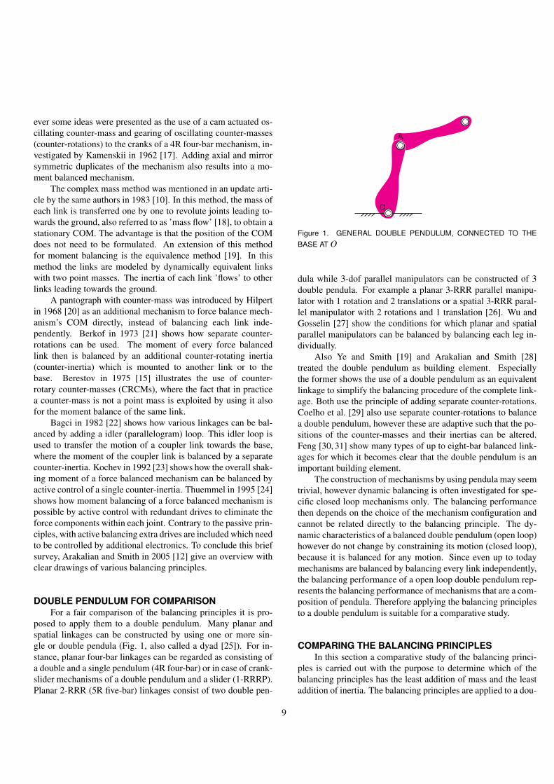
posed to apply them to a double pendulum. Many planar andspatial linkages can be constructed by using one or more sin-gle or double pendula (Fig. 1, also called a dyad [25]). For in-stance, planar four-bar linkages can be regarded as consisting ofa double and a single pendulum (4R four-bar) or in case of crank-slider mechanisms of a double pendulum and a slider (1-RRRP).Planar 2-RRR (5R five-bar) linkages consist of two double pen-
A
O
Figure 1. GENERAL DOUBLE PENDULUM, CONNECTED TO THEBASE AT O
dula while 3-dof parallel manipulators can be constructed of 3double pendula. For example a planar 3-RRR parallel manipu-lator with 1 rotation and 2 translations or a spatial 3-RRR paral-lel manipulator with 2 rotations and 1 translation [26]. Wu andGosselin [27] show the conditions for which planar and spatialparallel manipulators can be balanced by balancing each leg in-dividually.
Also Ye and Smith [19] and Arakalian and Smith [28]treated the double pendulum as building element. Especiallythe former shows the use of a double pendulum as an equivalentlinkage to simplify the balancing procedure of the complete link-age. Both use the principle of adding separate counter-rotations.Coelho et al. [29] also use separate counter-rotations to balancea double pendulum, however these are adaptive such that the po-sitions of the counter-masses and their inertias can be altered.Feng [30, 31] show many types of up to eight-bar balanced link-ages for which it becomes clear that the double pendulum is animportant building element.
The construction of mechanisms by using pendula may seemtrivial, however dynamic balancing is often investigated for spe-cific closed loop mechanisms only. The balancing performancethen depends on the choice of the mechanism configuration andcannot be related directly to the balancing principle. The dy-namic characteristics of a balanced double pendulum (open loop)however do not change by constraining its motion (closed loop),because it is balanced for any motion. Since even up to todaymechanisms are balanced by balancing every link independently,the balancing performance of a open loop double pendulum rep-resents the balancing performance of mechanisms that are a com-position of pendula. Therefore applying the balancing principlesto a double pendulum is suitable for a comparative study.
COMPARING THE BALANCING PRINCIPLESIn this section a comparative study of the balancing princi-
ples is carried out with the purpose to determine which of thebalancing principles has the least addition of mass and the leastaddition of inertia. The balancing principles are applied to a dou-
9

l2
l1
A
O
m I2 2
a1
a2
q2
q1
Figure 2. SIMPLIFIED DOUBLE PENDULUM WITH LUMPED MASS
ble pendulum and for each principle the equations for the totalmass and the reduced inertia are derived. With a numerical ex-ample the balancing principles are evaluated and compared.
To obtain a force balanced double pendulum, link mass re-distribution or an additional pantograph with one counter-masscan be applied. Link mass redistribution in this case means thateach link individually must be force balanced about its pivotwhich can be done by using counter-masses.
The moment of a force balanced double pendulum canbe balanced by using counter-rotary counter-masses (CRCMs),separate counter-rotations (SCR), an idler loop with separatecounter-rotations (IL), and by duplicating the mechanism (DM).A pantograph with one counter-mass can not be balanced by us-ing counter-inertias with a constant inertia tensor. This is becausethe mass distribution of a force balanced mechanism with a pan-tograph depends on the position of the links. Hence the inertiatensor of the mechanism is not constant and the linear and an-gular momentum of the mechanism will not be constant but bedependent on the linkage position and velocity. Solutions thenwill become very complex.
Although it is possible to balance the moment of a doublependulum actively, this comparative study is restricted to passivebalancing principles only.
In the remainder of this section, first the general equationsfor the linear and angular momentum are given since from thesethe balance conditions and the equations for the total mass andreduced inertia can be derived. Subsequently, the balancing prin-ciples are treated one by one and their equations for the total massand reduced inertia are obtained. A numerical example is carriedout and the performance of the balancing principles is judged byusing a proposed MI-factor.
Momentum, Mass, Inertia and MI-FactorFigure 2 shows the initial double pendulum which is mod-
eled to have two links l1 and l2 and a lumped mass m2 with iner-tia I2 at the end of link 2. This lumped mass represents the massdistribution of link 2. For the ease of calculation, the mass andinertia of link 1 is neglected. However including them is possi-
ble and will not influence the way the results are obtained. Tobalance this planar double pendulum, the linear and angular mo-mentum about the origin O in the x-y plane must be constant andcan be written as, respectively:
pO = ∑i
(miri +m∗i r∗i ) (1)
hO,z = ∑i(Iiαi + I∗i α∗i +(ri×miri)z +(r∗i ×m∗
i r∗i )z) (2)
with i being the link number, ri the position vector of mi, Ii theinertia of mi, and αi the absolute angular velocity of link i. Theasterisk (.)* is used to indicate the balancing parameters. Thetotal mass of the mechanism can be calculated as:
mtot = ∑i(mi +m∗
i ) (3)
For planar motion within the x-y plane, the z-component of thelinear momentum and the x- and y-component of the angular mo-mentum are zero (and conserved) by definition.
For the comparison of the inertia, the reduced inertia is usedas it is described in [32]. This is the inertia reduced to the in-put angles, angle θ1 and θ2 in this case which are the relativeangles between two connected links. The reduced inertia can beobtained from the kinetic energy equations as:
TO =12
Iredθ1
θ21 (4)
TA =12
Iredθ2
θ22 (5)
in which Iredθ1
and Iredθ2
are the reduced inertia moments about Oand A respectively.
To judge the performance of the balancing principles, a fac-tor is proposed that measures both the mass increase and the in-ertia increase of the balanced mechanism and where the relativeimportance of the mass and inertia is included. This Mass-Inertia(MI-) factor is defined as:
MI = wM · m+∑j
w j · I j (6)
where wM and w j are respectively the weight factors for the massand the inertia and m and I j are respectively the dimensionlessnumbers for the mass and the reduced inertia of input angle j.These numbers are the ratios of the mass and inertia before andafter balancing respectively and are calculated with:
m =mtot
motot
(7)
10

A
Oq
1
q2
k1
k2
l2
l1
m I2 2l
*
2
l*
1
m*2 I*2
m*1 1I*
a2
B
C
dO
dB
dA
dC
q*
2
q*
1
Figure 3. BALANCED DOUBLE PENDULUM BY USING COUNTER-ROTARY COUNTER-MASSES WITH k1 = k2 =−4
I j =Ired
j
Ired,oj
(8)
where motot and Ired,o
j are respectively the total mass and reducedinertia per input angle of the mechanism before balancing andmtot and Ired
j respectively the total mass and reduced inertia afterbalancing. The best balancing principle regarding the additionalmass and additional inertia then is the principle with the low-est value for the MI-factor. Since choosing the weights means atrade off between mass and inertia, the characteristic MI-factoris defined as the MI-factor in which all weights are equal to one.
Since the reduced inertia Iredθ1
of the initial double pendulumin Fig. 2 is not constant, the value for the reduced inertia is cho-sen for a position halfway the position of the minimal and maxi-mal inertia value, which for the double pendulum is for θ2 = π
2 .The reduced inertia of the double pendulum before balancingthen becomes:
Ired,oθ1
= I2 +m2(l21 + l2
2) (9)
Balancing by using Counter-Rotary Counter-MassesA double pendulum balanced by using counter-rotary
counter-masses is shown in Fig. 3. Link 2 is force balanced aboutA by a counter-mass m∗
2, which is not a point mass but has an in-ertia I∗2 . This counter-mass is placed at point C of link 2. For theforce balance of the linkage about the origin O, mass m∗
1 with in-ertia I∗1 is added to link 1 at point B. The moment balance of link2 is obtained by a gear attached to link 1 at A. This gear drives thecounter-mass m∗
2 by using a belt (or chain) by which m∗2 will ro-
tate in opposite direction of link 2 (negative transmission ratio).
Similarly, the moment balance of the complete linkage about Ois obtained by a gear attached to the base at O that drives m∗
1 inopposite direction of link 1.
The positions of the counter-masses can be written in vectornotation [x,y,z]T as:
r∗1 =
−l∗1 cosθ1−l∗1 sinθ1
0
r2 =
l1 cosθ1 + l2 cosα2l1 sinθ1 + l2 sinα2
0
r∗2 =
l1 cosθ1− l∗2 cosα2l1 sinθ1− l∗2 sinα2
0
where α2 = θ1 +θ2−π is the angle between link 2 and the hor-izontal. With the derivatives of the position vectors the linearmomentum becomes:
pO =
(m∗1l∗1 −m2l2−m∗
2l∗2)θ1 sinθ1−(m2l2−m∗
2l∗2)α2 sinα2(−m∗
1l∗1 +m2l2 +m∗2l∗2)θ1 cosθ1+
(m2l2−m∗2l∗2)α2 cosα2)0
(10)
A constant linear momentum for any motion is found for the fol-lowing force balance conditions:
m∗2l∗2 = m2l2 (11)
m∗1l∗1 = (m2 +m∗
2)l1 (12)
Assuming that these force balance conditions hold, the angularmomentum about the z-axis can be written as:
hO,z = I2(θ1 + θ2)+ I∗2 (θ1 + θ∗2)+ I∗1 θ∗1 +(r2×m2r2)z +(r∗1×m∗
1r∗1)z +(r∗2×m∗2r∗2)z
= (I2 + I∗2 +m2l22 +m∗
1l∗21 +m∗
2l∗22 +(m2 +m∗
2)l21)θ1 +
I∗1 θ∗1 +(I2 +m2l22 +m∗
2l∗22 )θ2 + I∗2 θ∗2 (13)
The kinematic relations of the CRCMs depend on the gear ratiosand for the belt transmissions of Fig. 3 write:
θ∗1 =(
1− dO
dB
)θ1 = k1θ1 (14)
θ∗2 =(
1− dA
dC
)θ2 = k2θ2 (15)
with dO, dA, dB and dC being the diameter of the gears at O, A,B and C respectively. The transmission ratios k1 and k2 attain
11

a negative value for a counter-rotation. Substituting the kine-matic relations of Eqn. (14) and (15), the angular momentum ofEqn. (13) can be rewritten as:
hO,z = (I2 + I∗2 +m2l22 +m∗
1l∗21 +
m∗2l∗2
2 +(m2 +m∗2)l
21 + k1I∗1 )θ1 +
(I2 +m2l22 +m∗
2l∗22 + k2I∗2 )θ2 (16)
A constant angular momentum is obtained if:
I∗1 =I2 + I∗2 +m2l2
2 +m∗1l∗2
1 +m∗2l∗2
2 +(m2 +m∗2)l
21
−k1(17)
I∗2 =I2 +m2l2
2 +m∗2l∗2
2−k2
(18)
The reduced inertia of the mechanism can be calculated fromthe kinetic energy equations Eqn. (4) and (5) as:
TO =12
(I2 + I∗2 +m2l2
2 +m∗1l∗2
1 +m∗2l∗2
2 +(m2 +m∗2)l
21)
θ21 +
12
I∗1 θ∗21 (19)
TA =12
(I2 +m2l2
2 +m∗2l∗2
2)
θ22 +
12
I∗2 θ∗22 (20)
Substituting Eqn. (14) and (15), the reduced inertia per input an-gle becomes:
Iredθ1
= I2 + I∗2 +m2l22 +m∗
1l∗21 +m∗
2l∗22 +(m2 +m∗
2)l21 + k2
1I∗1(21)
Iredθ2
= I2 +m2l22 +m∗
2l∗22 + k2
2I∗2 (22)
Note that these quantities are equal to the inertia terms of the an-gular momentum of Eqn. (16), but with the transmission ratiossquared. The total mass of the CRCM-balanced double pendu-lum can be calculated with:
mtot = m∗1 +m2 +m∗
2 (23)
Balancing by using Separate Counter-RotationsFigure 4 shows the principle of separate counter-rotations
applied to the double pendulum. The force balance of this link-age is obtained in the same way as with the CRCM-principle,by adding the two counter-masses m∗
1 and m∗2. This means that
the force balance conditions of Eqn. (11) and (12) are valid forthis principle too. The moment balance however is obtained dif-ferently. For the moment balance of link 2, a gear attached to
A
O
q1
q2
k1
k2
l2
l1
m I2 2l*
2
l*
1
O’
m*2 I*2
m*1 1I*
m*cr,1 cr,1I*
m*cr,2 cr,2I*
a2
B
C
dA
dO,2
dO’
dO,1
q*
2
q*
1
Figure 4. BALANCED DOUBLE PENDULUM BY USING COUNTER-MASSES AND SEPARATE COUNTER-ROTATIONS AT THE BASE WITHk1 = k2 =−4
link 2 at A drives an addition element with mass m∗cr,2 and inertia
I∗cr,2, which rotates about O in opposite direction of link 2. Themoment balance of the linkage about O is obtained by a gear at-tached to link 1 that drives another additional element with massm∗
cr,1 and inertia I∗cr,1. Since m∗cr,1 and m∗
cr,2 are mounted to thebase, they do not influence the force balance of the moving link-age. This would not be the case if m∗
cr,2 would be attached to l1elsewhere than at O, which would lead to an increase of mass andinertia. The angular momentum about the z-axis of this balanceddouble pendulum can be written as:
hO,z = (I2 + I∗2 )(θ1 + θ2)+ I∗1 θ1 + I∗cr,1θ∗1 + I∗cr,2(θ1 + θ∗2)+(r2×m2r2)z +(r∗1×m∗
1r∗1)z +(r∗2×m∗2r∗2)z
= (I∗1 + I2 + I∗2 +m2l22 +m∗
1l∗21 +m∗
2l∗22 +
(m2 +m∗2)l
21 + I∗cr,2)θ1 +
I∗cr,1θ∗1 +(I2 + I∗2 +m2l22 +m∗
2l∗22 )θ2 + I∗cr,2θ∗2 (24)
For this principle, the transmission ratios of the kinematic rela-tions Eqn. (14) and (15) are:
k1 = −dO,1
dO′k2 =− dA
dO,2
with dO,1, dO,2, dO′ and dA being the diameter of the large gearat O, the small gear at O, and the gears at O′ and A respectively.
12
With Eqn. (14) and (15) the angular momentum becomes:
hO,z = (I∗1 + I2 + I∗2 +m2l22 +m∗
1l∗21 +m∗
2l∗22 +
(m2 +m∗2)l
21 + I∗cr,2 + k1I∗cr,1)θ1 +
(I2 + I∗2 +m2l2
2 +m∗2l∗2
2 + k2I∗cr,2)
θ2 (25)
For the following conditions the angular momentum is constant:
I∗cr,1 =I∗1 + I2 + I∗2 +m2l2
2 +m∗1l∗2
1 +m∗2l∗2
2 +(m2 +m∗2)l
21 + I∗cr,2
−k1(26)
I∗cr,2 =I2 + I∗2 +m2l2
2 +m∗2l∗2
2−k2
(27)
The reduced inertias can be derived from the kinetic energy equa-tion of Eqn. (4) and (5) or from the angular momentum as wasdone for the CRCM-principle. Per input angle these become:
Iredθ1
= I∗1 + I2 + I∗2 +m2l22 +m∗
1l∗21 +m∗
2l∗22 +
(m2 +m∗2)l
21 + I∗cr,2 + k2
1I∗cr,1 (28)
Iredθ2
= I2 + I∗2 +m2l22 +m∗
2l∗22 + k2
2I∗cr,2 (29)
The total mass of the double pendulum balanced by using sepa-rate counter-rotations can be written as:
mtot = m∗1 +m2 +m∗
2 +m∗cr,1 +m∗
cr,2 (30)
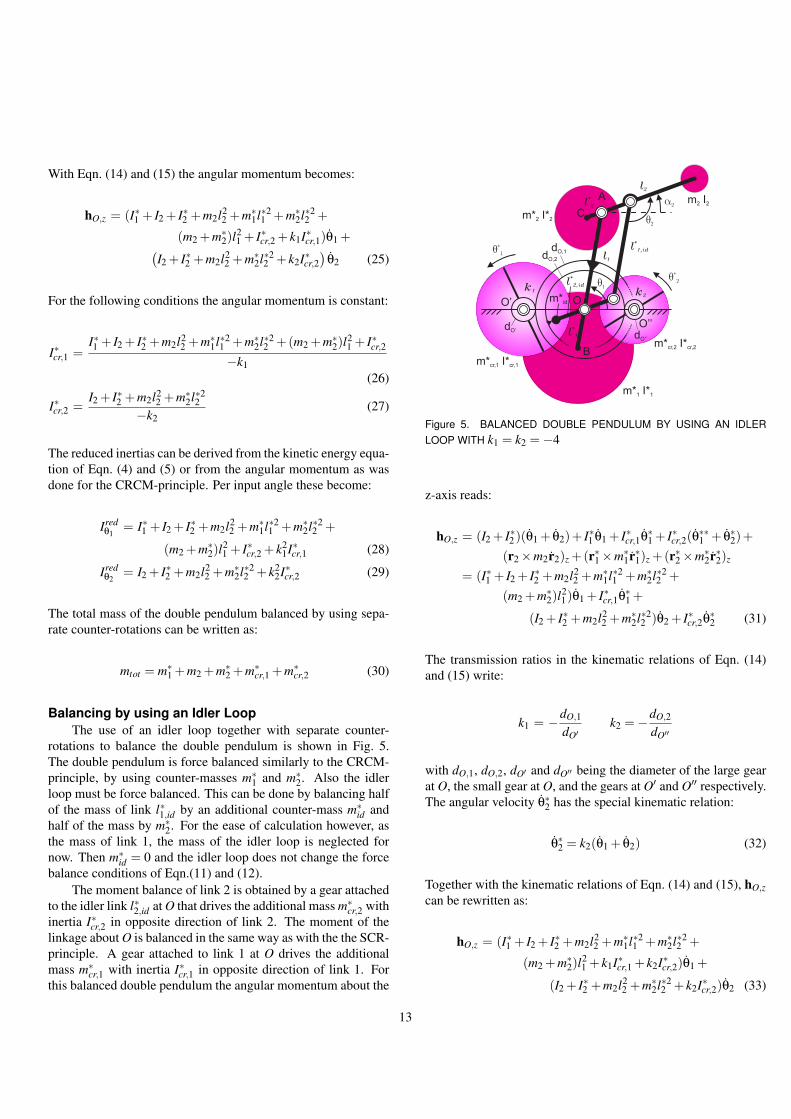
Balancing by using an Idler LoopThe use of an idler loop together with separate counter-
rotations to balance the double pendulum is shown in Fig. 5.The double pendulum is force balanced similarly to the CRCM-principle, by using counter-masses m∗
1 and m∗2. Also the idler
loop must be force balanced. This can be done by balancing halfof the mass of link l∗1,id by an additional counter-mass m∗
id andhalf of the mass by m∗
2. For the ease of calculation however, asthe mass of link 1, the mass of the idler loop is neglected fornow. Then m∗
id = 0 and the idler loop does not change the forcebalance conditions of Eqn.(11) and (12).
The moment balance of link 2 is obtained by a gear attachedto the idler link l∗2,id at O that drives the additional mass m∗
cr,2 withinertia I∗cr,2 in opposite direction of link 2. The moment of thelinkage about O is balanced in the same way as with the the SCR-principle. A gear attached to link 1 at O drives the additionalmass m∗
cr,1 with inertia I∗cr,1 in opposite direction of link 1. Forthis balanced double pendulum the angular momentum about the
A
O
q1k
1 k2
l2
l1
m I2 2l*
2
l*
1
O’
m*2 I*2
m*1 1I*
m*cr,1 cr,1I*
m*cr,2 cr,2I*
q2
a2
l*
1,id
m*id
l*
2,id
O’’
B
C
dO,1dO,2
dO’dO’’
q*
1
q*
2
Figure 5. BALANCED DOUBLE PENDULUM BY USING AN IDLERLOOP WITH k1 = k2 =−4
z-axis reads:
hO,z = (I2 + I∗2 )(θ1 + θ2)+ I∗1 θ1 + I∗cr,1θ∗1 + I∗cr,2(θ∗∗1 + θ∗2)+
(r2×m2r2)z +(r∗1×m∗1r∗1)z +(r∗2×m∗
2r∗2)z
= (I∗1 + I2 + I∗2 +m2l22 +m∗
1l∗21 +m∗
2l∗22 +
(m2 +m∗2)l
21)θ1 + I∗cr,1θ∗1 +
(I2 + I∗2 +m2l22 +m∗
2l∗22 )θ2 + I∗cr,2θ∗2 (31)
The transmission ratios in the kinematic relations of Eqn. (14)and (15) write:
k1 = −dO,1
dO′k2 =−dO,2
dO′′
with dO,1, dO,2, dO′ and dO′′ being the diameter of the large gearat O, the small gear at O, and the gears at O′ and O′′ respectively.The angular velocity θ∗2 has the special kinematic relation:
θ∗2 = k2(θ1 + θ2) (32)
Together with the kinematic relations of Eqn. (14) and (15), hO,zcan be rewritten as:
hO,z = (I∗1 + I2 + I∗2 +m2l22 +m∗
1l∗21 +m∗
2l∗22 +
(m2 +m∗2)l
21 + k1I∗cr,1 + k2I∗cr,2)θ1 +
(I2 + I∗2 +m2l22 +m∗
2l∗22 + k2I∗cr,2)θ2 (33)
13

A
Oq
1
q2
q2
q2
q2
q1
q1
q1
l*
2l
*
2
A’’A’’’
A’
O’
O’’’ O’’
l*
1l
*
1
l2
l1
m I2 2m* I*2 2
m* I*2 2 m* I*2 2
l*
1
l*
2
a2
Figure 6. BALANCED DOUBLE PENDULUM BY USING AXIAL ANDMIRROR SYMMETRIC MECHANISM DUPLICATES
A constant angular momentum is found under the conditions:
I∗cr,1 =I∗1 + I2 + I∗2 +m2l2
2 +m∗2l∗2
2 +U + k2I∗cr,2
−k1(34)
I∗cr,2 =I2 + I∗2 +m2l2
2 +m∗2l∗2
2−k2
(35)
with U = m∗1l∗2
1 +(m2 + m∗2)l
21 . The inertia I∗cr,1 turns out to be
dependent on both transmission ratios k1 and k2. Deriving thereduced inertia per input angle from Eqn (4) and (5) results into:
Iredθ1
= I∗1 + I2 + I∗2 +m2l22 +m∗
1l∗21 +m∗
2l∗22 +
(m2 +m∗2)l
21 + k2
1I∗cr,1 + k22I∗cr,2 (36)
Iredθ2
= I2 + I∗2 +m2l22 +m∗
2l∗22 + k2
2I∗cr,2 (37)
The total mass can be calculated as:
mtot = m∗1 +m2 +m∗
2 +m∗cr,1 +m∗
cr,2 (38)
Balancing by using Duplicate MechanismsBalancing the double pendulum by adding axial and mir-
ror symmetric duplicates is shown in Fig. 6. Necessary is that
Table 1. PARAMETER VALUES
m2 = 0.3 [kg] l1 = 0.25 [m] t = 0.01 [m]
I2 = 184 [kgmm2] l2 = 0.25 [m] ρ = 7800[kgm−3
the duplicates move synchronously with the initial double pen-dulum. For link 1 this is managed by gears at O which have agear (and transmission) ratio of -1. For link 2 no practical solu-tion is illustrated in Fig. 6, however there are various ways. Forinstance by having the four drives of link 2 of each double pen-dulum move synchronously. The linear and angular momentumof the initial double pendulum about the z-axis can be written as:
pO =
−m2l1θ1 sinθ1−m2l2α2 sinα2m2l1θ1 cosθ1 +m2l2α2 cosα2)
0
(39)
hO = I2(θ1 + θ2)+ r2×m2r2
= (I2 +m2(l21 + l2
2)−2m2l1l2 cosθ2)θ1 +(I2 +m2l2(l2− l1 cosθ2))θ2 (40)
These are dependent on the position and velocity of the mecha-nism. Since the horizontal duplicate rotates in opposite directionof the initial double pendulum, its angular momentum is equalbut opposite. Therefore they together form a moment balancedset and also the horizontal forces are balanced. However to bal-ance in vertical direction, two more duplicates are necessary inthis direction, resulting in a total of four equal and coupled mech-anisms. The reduced inertia of the complete set of mechanismscan be calculated as:
Iredθ1
= 4(I2 +m2(l21 + l2
2)−2m2l1l2 cosθ2) (41)
Iredθ2
= 4(I2 +m2l22) (42)
and the total mass becomes:
mtot = 4m2 (43)
The reduced inertia Iredθ1
depends on angle θ2 which results into aminimum value for θ2 = 0 and a maximum value for θ2 = π.
Numerical ExampleFor the numerical example, the counter-masses and counter-
inertias are modeled as circular discs with thickness t and a ma-terial density ρ. The mass and inertia of a counter-mass then arerelated by:
mi = ρπtR2i
Ii = 12 mR2
i
}⇒ m2
i = 2ρπtIi (44)
14

Table 2. LENGTHS OF CM-LINKS
l1
*
[m]
l2
*[m]
0.070
0.024
k1=k :2 -1
0.099
0.045
-4
0.118
0.062
-8
0.146
0.090
-16
Table 3. RESULTS OF TOTAL MASS AND REDUCED INERTIAS FOREACH PRINCIPLE AND FOR VARIOUS TRANSMISSION RATIOS
DuplicateMechanisms
SeparateCR
IdlerLoopCRCM
Total Mass [kg]
TotalInertia[kgm ]
2
1.2038.78 37.6316.01
Ired
q1
Ired
q2
1.362 1.2790.640
0.083 0.0830.041 0.076
k1=k =-12
7.35e 0.30-4< <I
red
q1
Total Mass [kg]
TotalInertia[kgm ]
2
14.33 13.936.89
Ired
q1
Ired
q2
1.275 1.2400.992
0.140 0.1400.112
k1=k =-42
Total Mass [kg]
TotalInertia[kgm ]
2
9.36 9.084.68
Ired
q1
Ired
q2
1.699 1.6691.484
0.239 0.2390.213
k1=k =-82
Total Mass [kg]
TotalInertia[kgm ]
2
6.13 5.913.09
Ired
q1
Ired
q2
2.531 2.5032.650
0.461 0.4610.488
k1=k =-162
By using Eqn. (11), (18) and (44), the transmission ratio k2 of theCRCM-principle can be written such that it depends on the onlybalancing parameter l∗2 :
k2 = −2ρπtl∗22 (I2 +m2l2
2 +m2l2l∗2)m2
2l22
(45)
Equivalently, by using Eqn. (12) and (17), the transmission ratiok1 of the CRCM-principle can be written to depend on l∗1 and l∗2as:
k1 = −2ρπtl∗21 (I2 +m2V )(
1+ l2l∗2
)2m2
2l21
(46)
with V =(
l22
2ρπtl∗22
+(
1+ l2l∗2
)(l1l∗1 + l2
1)+ l2l∗2 + l2
2
). This
means that if the transmission ratios are chosen, link lengths l∗1and l∗2 of the CRCM-principle are determined and vise versa. For
Table 4. MASS-INERTIA VALUES FOR VARIOUS WEIGHTS FOR THEMASS AND INERTIA ADDITION; WHEN THE INERTIA OF LINK 2 ISFOUND VERY IMPORTANT AND MASS NOT, THE DM-PRINCIPLE HASNOT ANYMORE THE LOWEST MI-VALUE; THE OTHER PRINCIPLESHAVE A MINIMUM MI-VALUE WHICH IS FOR THE CRCM-PRINCIPLETHE LOWEST AND FOR THE LOWEST TRANSMISSION RATIO
DMSCR ILCRCM
8 MI 16< <170 16473k1=k =-12wM=189 8755k1=k =-42w1=189 8766k1=k =-82w2=1112 110106k1=k =-162
k1=k =-12wM=2k1=k =-42w1=1k1=k =-82w2=1k1=k =-162
12 MI 28< <210 20292k1=k =-12wM=1130 12787k1=k =-42w1=2147 144117k1=k =-82w2=2203 201202k1=k =-162
20 MI 28< <58 5628k1=k =-12wM=071 7056k1=k =-42w1=1108 10795k1=k =-82w2=5189 188199k1=k =-162
12 MI 20< <299 289126
137 13378
120 11782
132 130117
MI-values
the parameter values of Table 1 and for k1 = k2, for four differ-ent transmission ratios these resulting link lengths are given inTable 2. For a fair comparison, these link lengths and values arealso used for the other principles which do not have this restric-tion. This means that the double pendulum is identical for eachprinciple. The results for the total mass and the reduced inertiaof each principle are shown in Table 3.
For the calculation of the MI-factor, from the numericalexample the total mass and reduced inertias before balancingof Eqn. (7) and (8) are respectively mo
tot = 0.3, Ired,oθ1
= 37684
[kgmm2] and Ired,oθ2
= 18934 [kgmm2]. For various combinationsof weight-values, the resulting MI-values for the balancing prin-ciples are shown in Table 4.
EvaluationFirst of all it is noted that all figures of the balanced dou-
ble pendulum in this article are drawn to scale by which thedifferences between the principles in terms of counter-mass andcounter-rotation size (and therefore, given fixed disk thickness,their mass) are visualized.
It might be surprising that simply duplicating the doublependulum two times results into the least total mass of all princi-ples, which is four times the initial mass. For the other principlesthe total mass is much larger. For all transmission ratios, the to-tal mass of the CRCM-balanced double pendulum is apparentlylower than that of the SCR- and IL-principle, which is because
15

of the two additional counter-rotations for the latter two. Theselatter two principles show a relatively small difference, the totalmass of the IL-principle is slightly lower. The reason for this isthe appearance of transmission ratio k2 in the equation for inertiaI∗cr,1 of the IL-principle (Eqn. (34)), by which the counter-inertiais smaller and has a lower mass than inertia I∗cr,1 of the SCR-principle (Eqn. (26)). If the mass and inertia of the idler loopwould be included, than the difference between the two princi-ples may vanish.
The inertia Iredθ1
of the DM-principle depends on the angle θ2and therefore can attain a low but also a high value. The max-imum Ired
θ1however is the lowest of all principles for any trans-
mission ratio. The maximum inertia Iredθ2
is larger than that ofthe CRCM-principle for k1 = k2 = 1, but smaller than that ofthe other principles. For transmission ratios −4 and larger, it issmaller than all other principles.
Comparing the equations for the inertia Iredθ1
(Eqn. (21), (28)and (36)) shows that the equation of the CRCM-principle has twoelements less than the equations of the SCR- and IL-principle.For the latter two, both inertias I∗cr,1 and I∗cr,2 appear. For the IL-principle these are multiplied by respectively k2
1 and k22, while for
the SCR-principle they are multiplied by respectively k21 and 1.
This explains the different results for Iredθ1
between the SCR- andIL-principle.
The results show that for low transmission ratios the CRCM-principle has a lower inertia Ired
θ1than the SCR- and IL-principle,
while for transmission ratios k1 = k2 = −16 it is larger. Thismeans that there exists a break-even point. For the CRCM-principle the equation for the inertia Ired
θ2(Eqn. (22)) has one el-
ement less. As for the inertia Iredθ1
there exists a break-even pointtoo. Since for the SCR- and IL-principle the Equations (29) and(37) are identical, their values for the inertia Ired
θ2are equal.
The values of the MI-factor of the balancing principles areshown in Table 4. For the characteristic MI-factor, wM = w1 =w2 = 1, Table 4 shows that the DM-principle has the lowestvalues. For the other principles the MI-values of the CRCM-principle are the lowest. There exists a minimum MI-value be-tween −1 < k < −16 which is for the CRCM-principle for thelowest transmission ratios.
If the mass is found more important then the inertia, e.g.wM = 2, then this is in advantage of the DM- and CRCM-principles. The transmission ratios of the minimum MI-valuesbecome larger. If the inertia is more important, e.g. wM = 1and w1 = w2 = 2, then the transmission ratios of the minimumMI-values become smaller. If the mass is not of importance andbut the inertia of link 2 is very much, then for wm = 0, w1 = 1and w2 = 5, then for transmission ratios of 1 the MI-value ofthe CRCM-principle is equal to the maximum MI-value of theDM-principle.
Since the DM-principle shows the lowest values for the MI-factor in all cases, this principle is assumed to be the most advan-
tageous for low mass and low inertia dynamic balancing. Nextbest is the CRCM-principle. This principle however is less com-plex than the DM-principle and needs a much smaller space. Thearea of the complete balanced mechanism is more than two timessmaller for the CRCM-principle.
DISCUSSIONAlthough the elements I∗cr,1 and I∗cr,2 are used as counter-
inertia for the moment balance only, designing them as rings in-stead of discs would decrease the total mass of the SCR- andIL-principle. If the counter-masses m∗
1 and m∗2 would be ring-
shaped, the inertia reduction of both the SCR- and IL-principlewould have been less, while that of the CRCM-principle wouldhave been larger. A ring-shaped design was not applied becauseextra parameters would have made the equations less transparent.However in practice, if possible, this certainly is worth consider-ing.
For the comparative study, link lengths l∗1 and l∗2 were chosento be equal for each principle. From the equations of the inertiasIredθ1
and Iredθ2
of each principle can be obtained that for increas-ing link lengths l∗1 and l∗2 , the reduced inertias increase while fordecreasing lengths the reduced inertias decrease. For increasinglink lengths, masses m∗
1 and m∗2 become smaller, but the mass of
the separate counter-rotations becomes larger. The detailed in-fluence of these and other parameters is an interesting topic forfuture research.
The results of Kochev [11] for a balanced 4R four-bar mech-anism were that the total mass of the mechanism with the SCR-principle was less than that with the IL-principle. However, thisarticle shows a lower total mass for IL-principle, which was ex-plained by a smaller design of counter-inertia I∗cr,1. This meansthat the difference between the results of Kochev and this articleare due to the the additional idler loop. However the position anddesign of the idler loop are arbitrary. The closer the parallel linksare placed together, the smaller is its influence on the total massand reduced inertia.
The number of balancing principles that were found to bal-ance a double pendulum were only four. Since the SCR- and IL-principle have much similarity, both make use of counter-massesand separate counter-rotations, these four balancing principlescan be classified into the three categories: (1) dynamic balancingby using counter-rotary counter-masses; (2) dynamic balancingby using counter-masses and separate counter-rotations; (3) dy-namic balancing by duplicating mechanisms. Since with (1) and(2) mechanism links are balanced individually and with (3) themechanism altogether, the approach to dynamic balancing can bearranged as in Fig. 7.
In this article, balancing the mechanism altogether showedto be most advantageous for low mass and low inertia dynamicbalancing.
16

dynamic balancing
balancing linksindividually
balancing mechanismsaltogether
counter-rotarycounter-masses
counter masses andseparate counter-rotations
duplicatemechanisms
Figure 7. APPROACH TO DYNAMIC BALANCING CAN BE CLASSI-FIED AS BALANCING THE LINKS INDIVIDUALLY OR THE MECH-ANISM ALTOGETHER; BALANCING LINKS INDIVIDUALLY IS DONEBY USING COUNTER-ROTARY COUNTER-MASSES OR BY USINGCOUNTER-MASSES AND SEPARATE COUNTER-ROTATIONS
CONCLUSIONIn this article, the fundamentals of dynamic balancing
were described, and balancing by using counter-rotary counter-masses, separate counter-rotations, an idler loop, and duplicatemechanisms were compared with respect to their required addi-tional mass and inertia. To this end, the principles were appliedto a double pendulum. A double pendulum was found to be arepresentative building element because many mechanisms canbe regarded as being composed of single and double pendula.
For each balancing principle the equation for the total massand inertia were derived. The Mass-Inertia (MI-) factor was pro-posed to judge the performance of the balancing principles re-garding the addition of mass and addition of inertia. The balanc-ing principles were classified as balancing links independently orbalancing the mechanism altogether (i.e. not link by link).
With a numerical example it was shown that the duplicatemechanisms principle adds the least mass to the initial mecha-nism compared to the other principles. As was clearly shown,the counter-rotary counter-mass principle has less mass additionthan the principles of separate counter-rotations and using anidler loop. The difference between the latter two is relativelysmall and will merely depend on the design of the idler loop.
Regarding the additional inertia, for low transmission ratiosthe counter-rotary counter-mass principle has a lower addition ofinertia than by using separate counter-rotations with or withoutan idler loop, while for high transmission ratios the use of sepa-rate counter-rotations with or without an idler loop is favorable.The duplicate mechanisms principle can only attain a transmis-sion ratio of −1, but for this value it has the least addition ofinertia of all principles for transmission ratios of −4 and larger.
From the values of the MI-factor, the DM-principle is foundmost advantageous for low-mass and low-inertia dynamic bal-ancing, which is a principle in which the mechanism is balancedaltogether. Using counter-rotary counter-masses is more advan-tageous than balancing by using separate counter-rotations withor without an idler loop. Generally, the additional mass and in-ertia are indeed substantial, as Kochev stated [11]. This should
however encourage research on low mass and low inertia balanc-ing.
NOMENCLATUREI inertiaIred reduced inertiaI ratio of inertia before and after balancingm massm ratio of mass before and after balancingl link lengthd gear diameterk transmission ratioα absolute angle of link with respect to reference frameθ relative angle between two linksr mass position vector(.)∗ balance propertypO linear momentum about the originhO angular momentum about the originT mechanism’s kinetic energyMI Mass-Inertia factor
REFERENCES[1] Lowen, G. G., and Berkof, R. S., 1968. “Survey of investi-
gations into the balancing of linkages”. Journal of Mecha-nisms, 3, pp. 221–231.
[2] Ishida, K., and Matsuda, T., 1979. “Performance character-istics and working comfortableness of forest workers of anew non-vibrating chain saw utilizing perfectly balancedrotation-reciprocation device”. Proceedings of the FifthWorld Congress of Theory of Machines and Mechanisms,ASME, pp. 951–954.
[3] Raaijmakers, R., 2007. “Besi zoekt snelheidslimiet pakkenen plaatsen op (transl: Besi attacks the speedlimit for pickand place motion)”. Mechatronica nieuws (dutch maga-zine), pp. 26–31.
[4] Van der Linde, R. Q., 1999. “Design, analysis and controlof a low power joint for walking robots, by phasic activationof mckibben muscles”. IEEE Trans. Robotics and Automa-tion, 15(4), pp. 599–604.
[5] Brown, G. W., 1987. Suspension system for supportingand conveying equipment, such as a camera, patent number:US-4710819.
[6] Rivin, E. I., 1979. “Principles and criteria of vibration iso-lation of machinery”. Journal of Mechanical Design, 101,pp. 682–692.
[7] Kochev, I. S., 1990. “Full shaking moment balancing ofplanar linkages by a prescribed input speed fluctuation”.Mechanism and Machine Theory, 25(4), pp. 459–466.
[8] Papadopoulos, E., and Abu-Abed, A., 1994. “Design andmotion planning for a zero-reaction manipulator”. Proc.
17

of IEEE Int. Conf. on Robotics and Automation, pp. 1554–1559.
[9] Agrawal, S. K., and Fattah, A., 2004. “Reactionless spaceand ground robots: Novel designs and concept studies”.Mechanism and Machine Theory, 39, pp. 25–40.
[10] Lowen, G. G., Tepper, F. R., and Berkof, R. S., 1983. “Bal-ancing of linkages - an update”. Mechanism and MachineTheory, 18(3), pp. 213–220.
[11] Kochev, I. S., 2000. “General theory of complete shakingmoment balancing of planar linkages: A critical review”.Mechanism and Machine Theory, 35, pp. 1501–1514.
[12] Arakelian, V. G., and Smith, M. R., 2005. “Shaking forceand shaking moment balancing of mechanisms: A histor-ical review with new examples”. Journal of MechanicalDesign, 127, pp. 334–339.
[13] Demeulenaere, B., 2004. Dynamic Balancing of Recipro-cating Machinery With Application to Weaving Machines -PhD. thesis.
[14] Yu, Y.-Q., and Jiang, B., 2007. “Analytical and experi-mental study on the dynamic balancing of flexible mecha-nisms”. Mechanism and Machine Theory, 42, pp. 626–635.
[15] Berestov, L. V., 1975. “Full dynamic balancing of ar-ticulated four-link chain”. Izv. Vyssh. Uchebn. Zaved.-Mashinostroenic, 11, pp. 62–65. (Russian).
[16] Herder, J. L., and Gosselin, C. M., 2004. “A counter-rotarycounterweight (CRCW) for light-weight dynamic balanc-ing”. Proceedings of DETC 2004, ASME,(DETC2004-57246).
[17] Kamenskii, V. A., 1968. “On the question of the balancingof plane linkages”. Journal of Mechanisms, 3, pp. 303–322.
[18] Yao, J., and Smith, M. R., 1993. “An improved complexmass method for force balancing of planar linkages”. Mech-anism and Machine Theory, 28(3), pp. 417–425.
[19] Ye, Z., and Smith, M. R., 1994. “Complete balancing ofplanar linkages by an equivalence method”. Mechanismand Machine Theory, 29(5), pp. 701–712.
[20] Hilpert, H., 1968. “Weight balancing of precision mechan-ical instruments”. Journal of Mechanisms, 3, pp. 289–302.
[21] Berkof, R. S., 1973. “Complete force and moment balanc-ing of inline four-bar linkages”. Mechanism and MachineTheory, 8, pp. 397–410.
[22] Bagci, C., 1982. “Complete shaking force and shaking mo-ment balancing of link mechanisms using balancing idlerloops”. Transactions ASME, Journal of Mechanical De-sign, 104(2), pp. 482–493.
[23] Kochev, I. S., 1992. “Active balancing of the frame shakingmoment in high speed planar machines”. Mechanism andMachine Theory, 27(1), pp. 53–58.
[24] Thuemmel, T., 1995. “Dynamic balancing of linkages byactive control with redundant drives”. Proc. 9th WorldCongress of the Theory of Machines and Mechanisms,pp. 970–974.
[25] Tsai, L. W., and Roth, B., 1972. “Design of dyads with he-lical, cylindrical, spherical, revolute and prismatic joints”.Mechanism and Machine Theory, 7, pp. 85–102.
[26] Gosselin, C. M., Vollmer, F., Cote, G., and Wu, Y.,2004. “Synthesis and design of reactionless three-degree-of-freedom parallel mechanisms”. IEEE Transactions onRobotics and Automation, 20(2), pp. 191–199.
[27] Wu, Y., and Gosselin, C. M., 2007. “On the dynamicbalancing of multi-dof parallel mechanisms with multi-ple legs”. Journal of Mechanical Design, 129, February,pp. 234–238.
[28] Arakelian, V. G., and Smith, M. R., 1999. “Completeshaking force and shaking moment balancing of linkages”.Mechanism and Machine Theory, 34, pp. 1141–1153.
[29] Coelho, T. A. H., Yong, L., and Alves, V. F. A., 2004. “De-coupling of dynamic equations by means of adaptive bal-ancing of 2-dof open-loop mechanisms”. Mechanism andMachine Theory, 39, pp. 871–881.
[30] Feng, G., 1990. “Complete shaking force and shaking mo-ment balancing of 26 types of four-, five-, and six-bar link-ages with prismatic pairs”. Mechanism and Machine The-ory, 25(2), pp. 183–192.
[31] Feng, G., 1991. “Complete shaking force and shaking mo-ment balancing of 17 types of eight-bar linkages only withrevolute pairs”. Mechanism and Machine Theory, 26(2),pp. 197–206.
[32] VDI2149, 1999. “Blatt 1: Getriebedynamik-starrkorpermechanismen (dynamics of mechanisms-rigid body mech-anisms)”. Verein Deutscher Ingenieure - Richtlinien.
18

CHAPTER 3-
COMPARATIVE ANALYSIS AND OPTIMIZATIONFOR LOW-MASS AND LOW-INERTIA DYNAMIC
BALANCING OF A 1-DOF ROTATABLE LINKBALANCED BY A COUNTER-ROTARY
COUNTER-MASS
V. van der Wijk †, J.L. Herder †, B. Demeulenaere ‡, C.M. Gosselin §
†Faculty of Mechanical Engineering, Delft University of Technology‡Department of Mechanical Engineering, KU Leuven
§Department of Mechanical Engineering, Laval University, Quebec
To be submitted to Journal of Mechanisms and Robotics
19

COMPARATIVE ANALYSIS AND OPTIMIZATION FOR LOW-MASS ANDLOW-INERTIA DYNAMIC BALANCING OF A 1-DOF ROTATABLE LINK BALANCED
BY A COUNTER-ROTARY COUNTER-MASS
V. van der Wijk †, J.L. Herder †, B. Demeulenaere ‡, C.M. Gosselin §
†Faculty of Mechanical Engineering, Delft University of Technology‡Department of Mechanical Engineering, KU Leuven
§Department of Mechanical Engineering, Laval University, Quebec
ABSTRACTMechanisms still cannot be dynamically balanced without a substantial increase of mass and inertia. This article addresses
the principle of balancing by using counter-rotary counter-masses (CRCMs), which has proved to have a potential for lowmass and low inertia balancing. This is because the counter-mass that is used for force balancing is also used for momentbalancing of the mechanism. The goal of this article is to optimize the CRCM-configuration and to investigate how it relates toother balancing principles in terms of low mass and low inertia addition. Therefore a CRCM-balanced 1-DOF rotatable link isanalyzed. The results are compared with the results of a balanced 1-DOF rotatable link with separate counter-rotations (SCR)and with mechanism duplicates (DM), which therefore are analyzed too. A numerical example is carried out and by using theMass-Inertia (MI-) factor the balancing principle with the least addition of mass and inertia is found. A physical model wasbuilt to put theory into practice.
The CRCM-principle was found to be better than the SCR-principle for low mass and low inertia dynamic balancing. Fora low material density or a thin shape of the CRCM, the CRCM-principle is better than the DM-principle. For a low additionof mass, the (counter-rotary) counter-mass has to be placed far away from the center of rotation while for a low inertia additionit has to be placed close to the center of rotation. Hence there is a trade-off between the addition of mass and the addition ofinertia. For low inertia addition the transmission ratio has to be small and the inertia of the CRCM has to be large.
INTRODUCTIONShaking forces and shaking moments are defined as the re-
sultant forces and resultant moments due to the mass and inertiaof the mechanism in motion. If these forces and moments existat the base of a mechanism, this base is unbalanced and will ex-hibit vibrations. Often unbalance is undesired. It induces noise,wear, fatigue problems [1], and discomfort [2]. Balanced manip-ulators however can have both low cycle times and high accuracysince waiting times for vibrations to die out are eliminated [3].In moving objects and vehicles, dynamic balance is important formaintaining their orientation [4, 5].
A disadvantage of today’s principles to balance mechanismsis that a substantial amount of additional mass and inertia is nec-essary, as clearly stated by Kochev [6] ”The price paid for shak-ing force and shaking moment balancing is discouraging”. Moreinertia means that more power is needed to drive the mechanismwhile more mass means more power to lift and control the objectin free space. Research therefore must be encouraged to focuson reducing this disadvantage.
To find balancing principles that allow a low addition ofmass and inertia, Herder and Gosselin [7] investigated a onedegree of freedom (DOF) rotatable link balanced by using acounter-rotary counter-mass (CRCM). In this principle, appliedto a 4-R four-bar linkage by Berestov [8], the counter-mass forthe force balance of one of the links is also used as counter-inertia for the moment balance of this link. Herder and Gosselinshowed that for their example this principle reduced the addi-tional mass by about 40% and reduced the additional inertia byabout 20% compared to balancing by adding separate counter-rotations (SCR) [9,10]. In [11] various balancing principles werecompared by applying them to a double pendulum, which alsoshowed the potential of balancing by using CRCMs. That CR-CMs are also useful for the synthesis of balanced mechanismsand allows to find the balancing conditions and inertia equationsof these mechanisms quickly, is shown in [12]. Both articles [7]and [11] however, do not reveal the relative importance of theparameters that influence the addition of mass and the additionof inertia.
20

The objective of this article is to optimize the CRCM-configurations and to investigate how it relates to other balancingprinciples in terms of low mass and low inertia addition. This isdone by applying the balancing principles to a 1-DOF rotatablelink, as was done in [7].
This paper is structured as follows. First from the conserva-tion of momentum method, the general balancing conditions andthe equations for the total mass and the inertia of the balancedmechanism are given. Then three CRCM-configurations are pre-sented and for a 1-DOF rotatable link the balance conditions,the mass equations and the inertia equations are derived. Thisis also done for the SCR-principle and both principles are com-pared analytically. By a numerical example these two principlesand the balancing principle of duplicating mechanisms (DM) [1]are compared. By using the Mass-Inertia (MI-) factor [11] theoptimal configuration for a low mass and low inertia addition aredetermined. Finally, the practical implementation of the CRCM-principle is discussed from the experience of building a physicalmodel of the CRCM-balanced 1-DOF rotatable link.
MOMENTUM, MASS, INERTIA AND MI-FACTORThe conservation of momentum method to obtain the con-
ditions for which a mechanism is balanced can be assumed tobe the most general balancing method. From [7, 11], if the lin-ear momentum of a mechanism is conserved, then the resultantforce is zero and the mechanism is force balanced. If the angu-lar momentum is conserved, then the resultant moment is zeroand the mechanism is moment balanced. Both force balance andmoment balance are necessary to have a (completely) balancedmechanism. Force balance must be clearly distinguished fromstatic balance. Static balance can also be obtained by maintain-ing the potential energy of the mechanism constant, for instanceby using springs. In fact, force balancing is a subset of staticbalancing.
For spatial motion, the equations of the linear and angularmomentum (momentum equations) about the origin O of a mech-anism can be written as respectively:
pO = ∑i(miri +m∗
i r∗i ) = mtot rCOM (1)
hO = ∑i(Iiωi + I∗i ω∗i + ri×miri + r∗i ×m∗
i r∗i ) (2)
in which i is the number of a mechanism link, mi the mass oflink i, ri the position vector of the center of mass (COM) of linki, rCOM the velocity vector of mechanism’s COM, Ii the inertiatensor of link i about its COM, and ωi the angular velocity vec-tor of link i. The asterisk (.)* is used to indicate the balancing
parameters. The total mass of the mechanism is calculated as:
mtot = ∑i(mi +m∗
i ) (3)
For planar motion in the x-y plane, the z-component of the linearmomentum and the x- and y-component of the angular momen-tum are zero (and conserved) by definition.
The inertia equations of the mechanism are the reduced in-ertia equations as defined in [13]. This is the inertia of the mech-anism reduced to the input angles and can be derived from thekinetic energy of the mechanism in motion or from the angularmomentum. This will be treated in the next section.
The Mass-Inertia (MI-) factor as described in [11] is used tofind the optimal configuration of each balancing principle and tofind the balancing principle which is the best for low mass andlow inertia dynamic balancing. The MI-factor is defined as:
MI = wM · m+∑j
w j · I j (4)
where wM and w j are the weight factors for the mass and the in-ertia, respectively, and m and I j are the mass ratio the reducedinertia ratio of input angle j, respectively. These ratios are cal-culated based on the mass and inertia before and after balancingaccording to, respectively:
m =mtot
motot
(5)
I j =Ired
j
Ired,oj
(6)
where motot and Ired,o
j are the total mass and reduced inertia perinput angle of the mechanism before balancing, respectively, andmtot and Ired
j the total mass and reduced inertia after balancing,respectively. A particular configuration is defined as optimized inthe design parameters when yielding the lowest MI-factor. Sub-sequently, different optimized balancing principles, applied toidentical non-balanced mechanisms, are compared based on theirMI-factors. The MI-factor where all weight factors are equal toone is the characteristic MI-factor of the balancing principle.
COUNTER-ROTARY COUNTER-MASS PRINCIPLEFigure 1 shows three possible CRCM-configurations for a 1-
DOF rotatable link. The link before balancing is modeled to havea lumped mass m with inertia I at a distance l. Since there is onlyone link, the index i was left out from the equations. The lumpedmass m represents the mass distribution (hence the inertia) of thelink.
21

m* I*
Okm I
l*
l
q
a)
q*
O
b)
O
c)
Figure 1. CRCM-BALANCED 1-DOF ROTATABLE LINK BY USING: A):BELT DRIVE, B): EXTERNAL GEARS, C): INTERNAL GEARS
For the force balance, a mass m∗ with inertia I∗ is placedat a distance l∗. For the moment balance, in Fig. 1a this massm∗ is driven with transmission ratio k by a belt (or chain) at-tached around a gear at O which is fixed to the base. When linkl is moved, m∗ will move in opposite direction (k is negative)which makes it a counter-rotary counter-mass. In Fig. 1b thisCRCM is driven by a pair of external gears, while Fig. 1c showsa configuration by using internal gears. For each configuration kcan be obtained from the gear diameters as k = 1− dO
dCRCM, with
diameters dO and dCRCM of the fixed gear at O and the CRCM-gear respectively. The latter gear is fixed to the CRCM but itsdiameter can differ from the diameter of the CRCM. The config-uration with external gears has an additional gear (in the middle)that rotates in the same direction as the link. This is disadvan-tageous since also the moment of this gear must be balanced bythe CRCM.
To find the balancing conditions and the equations for thetotal mass and total inertia of the 1-DOF rotatable link of Fig. 1,the positions of the two masses m and m∗ can be written in vectornotation [x,y,z]T respectively as:
r =
l cosθ1l sinθ1
0
r∗ =
−l∗ cosθ1−l∗ sinθ1
0
By substituting the derivatives of these position vectors intoEqn. (1) the linear momentum writes:
pO =
(−ml +m∗l∗)θsinθ(ml−m∗l∗)θcosθ
0
(7)
The linear momentum is conserved for any motion for the forcebalance condition:
m∗l∗ = ml (8)
The inertia tensors and angular velocity vectors are given as:
I =
Ixx 0 00 Iyy 00 0 I
I∗ =
I∗xx 0 00 I∗yy 00 0 I∗
ω =
00θ
ω∗ =
00θ∗
and including them into Eqn. (2) results into:
hO,z = Iθ+ I∗θ∗+(r×mr)z +(r∗×m∗r∗)z (9)
while hO,x = hO,y = 0 because of planar motion. If the force bal-ance condition of Eqn. (8) holds, the angular momentum of theforce balanced link about the z-axis can be written from Eqn. (9)as:
h0,z = (I +ml2 +m∗l∗2)θ+ I∗θ∗ (10)
Angular velocity θ∗ depends on θ by transmission ratio k and is:
θ∗ = kθ (11)
With this kinematic relation, h0,z becomes:
h0,z = (I +ml2 +m∗l∗2 + kI∗)θ (12)
The condition for which h0,z is constant is:
I∗ =I +ml2 +m∗l∗2
−k(13)
The reduced inertia can be obtained from the equation of the ki-netic energy [13], which writes:
TO =12
Iredθ θ2 (14)
22

m* I*
O
k
m I
l*
l
q
m*cr crI*
q*
Figure 2. BALANCED 1-DOF ROTATABLE LINK BY USING A SEPA-RATE COUNTER-ROTATION
The kinetic energy of the balanced link can be written as:
TO =12(I +ml2 +m∗l∗2)θ2 +
12
I∗θ∗2 (15)
Substituting the kinematic relation of Eqn. (11) results into:
TO =12(I +ml2 +m∗l∗2 + k2I∗)θ2 (16)
and the equation for the reduced inertia is becomes:
Iredθ = I +ml2 +m∗l∗2 + k2I∗ (17)
Note that this equation is equal to the inertia term of the angularmomentum in Eqn. (12), but with the transmission ratio squared.From Eqn. (3) the equation for the total mass is:
mtot = m+m∗ (18)
PRINCIPLE OF SEPARATE COUNTER-ROTATIONSThe CRCM-principle will be compared to a common way to
balance a linkage, namely by using separate counter-rotations forthe moment balance [9, 10]. For the 1-DOF rotatable link this isshown in Fig. 2. Here the counter-mass m∗ for the force balanceis mounted to the link l∗. To balance the moment, an additionalrotatable element with mass m∗
cr and inertia I∗cr is placed else-where on the base and is driven by a gear attached to the link atO. Since this additional element is mounted on the base, a con-stant linear momentum for this configuration is also obtained forthe force balance condition of Eqn. (8). With Eqn. (9) and (11),the angular momentum of this mechanism results into:
h0,z = (I + I∗+ml2 +m∗l∗2)θ+ I∗crθ∗
= (I + I∗+ml2 +m∗l∗2 + kI∗cr)θ (19)
The condition for a constant angular momentum then becomes:
I∗cr =I + I∗+ml2 +m∗l∗2
−k(20)
Equivalent to the CRCM-balanced link, the inertia equation canbe obtained from the angular momentum and writes:
Iredθ = I + I∗+ml2 +m∗l∗2 + k2I∗cr (21)
The equation for the total mass results into:
mtot = m+m∗+m∗cr (22)
PARAMETER DEPENDENCYComparing the moment balance condition, mass equation,
and inertia equation of both balancing principles results intoone obvious difference. Due to the extra element for the SCR-principle, an extra parameter appears in each equation. Further-more, the counter-moment for the CRCM-principle is producedby I∗, while for the SCR-principle by the additional I∗cr.
To evaluate what this would mean in a practical situation andto find the optimal set of parameter values for which the additionof mass and the addition of inertia are minimal, the design of themasses must be chosen. If for the configurations of Fig. 1 andFig. 2 the masses are modeled as solid discs of thickness t andradius Ri, it means that the mass and inertia of the masses arerelated by:
mi = ρπtR2i
Ii = 12 miR2
i
}⇒ m2
i = 2ρπtIi (23)
in which ρ is the material density. Collecting all equations forthe CRCM-principle results into the following set of equations:
Force Balance: ml = m∗l∗ (8)Dynamic Balance: I +ml2 +m∗l∗2 + kI∗ = 0 (13)
Inertia: Iredθ = I +ml2 +m∗l∗2 + k2I∗ (17)
Total Mass: mtot = m+m∗ (18)Design Relation: m∗2 = 2ρπtI∗ (23)
With m, I, l, t, and ρ known, there are 5 equations and 6 un-knowns. This means that if one of them is chosen, the other canbe calculated. By combining the equations, various relations canbe obtained where one balancing parameter depends on a singleother balancing parameter. Interesting are the following:
Iredθ (m∗) = I +ml2 +
m2l2
m∗ +2ρπtm∗2
(I +ml2 +
m2l2
m∗
)2
(24)
23

Table 1. PARAMETER VALUES
m = 0.3 [kg] l = 0.25 [m] ρ = 7800[kgm−3]
I = 184 [kgmm2] t = 0.01 [m]
Iredθ (l∗) = I +ml2 +mll∗+
2ρπtl∗2
m2l2
(I +ml2 +mll∗
)2(25)
k(m∗) = −2ρπtm∗2
(I +ml2 +
m2l2
m∗
)(26)
k(l∗) = −2ρπtl∗2
m2l2
(I +ml2 +mll∗
)(27)
With Eqn. (18), from Eqn. (24) and (26), the total mass-inertiarelation Ired
θ (mtot) and total mass-transmission ratio relationk(mtot) can be obtained respectively. The dependency of Ired
θ andk on the counter-mass length l∗ follows from Eqn. (25) and (27).
For the SCR-principle there exist 6 equations, one more thanfor the CRCM-principle do to the additional element. The col-lection of equations then becomes:
Force Balance: ml = m∗l∗ (8)Dynamic Balance: I +ml2 + I∗+m∗l∗2 + kI∗cr = 0 (20)
Inertia: Iredθ = I +ml2 + I∗+m∗l∗2 + k2I∗cr (21)
Total Mass: mtot = m+m∗+m∗cr (22)
Design Relations: m∗2 = 2ρπtI∗
m∗2cr = 2ρπtI∗cr (23)
Now there are 6 equations and 8 unknowns. This means twobalancing parameters (one of the original linkage and one of theadditional element) must be chosen to be able to calculated theothers. Using this set of equations, among others the followingrelations can be obtained:
Iredθ (m∗,m∗
cr) = I +ml2 +m∗2
2ρπt+
m2l2
m∗ +
2ρπtm∗2
cr
(I +ml2 +
m∗2
2ρπt+
m2l2
m∗
)2
(28)
Iredθ (k,m∗) = (1− k)
(I +ml2 +
m∗2
2ρπt+
m2l2
m∗
)(29)
k(m∗,m∗cr) = −2ρπt
m∗2cr
(I +ml2 +
m∗2
2ρπt+
m2l2
m∗
)(30)
With Eqn. (22), the total mass-inertia relation can be obtainedfrom Eqn. (28) and the total mass-transmission ratio relationfrom Eqn. (30).
0.5 1 1.5 2 2.5 3 3.5 4 4.5 510
−4
10−3
10−2
10−1
100
101
102
m* [kg]
I*=0.0056
−k =4
m*=1.65
l*=0.046
−k [−]
I* [kgm2]
l* [m]
Figure 3. CRCM DESIGN CHART
m* I*
O
k
m I
l*
l
q
Figure 4. SCALED CRCM-BALANCED LINK WITH k =−4
NUMERICAL EXAMPLEFor the numerical values of Table 1, the dependency of the
balancing parameters I∗, l∗ and k on the mass m∗ of the CRCM-principle is shown in Fig. 3. Note that the curves in these figuresare independent, the vertical values of each curve have differentdimensions. Figure 3 is a design chart since by choosing one ofthe parameters, the other can be read. For instance for k = −4it follows that m∗ = 1.65kg, I∗ = 0.0056kgm2 and l∗ = 0.046, asindicated by the dotted lines.
Figure 3 shows that for increasing counter-mass m∗ thelength l∗ and transmission ratio k decrease, but the inertia I∗ in-creases. Since from Eqn. (18) the total mass mtot is the sum ofm∗ and the constant mass m, this behavior is also true for therelations of l∗, k and I∗ with mtot .
To visualize the balanced link with solid disc of equal thick-ness, for k = −4 the CRCM-principle and SCR-principle aredrawn to scale in Fig. 4 and 5. Balancing the link by adding ax-ial and mirror duplicates of the link (DM-principle) is shown inFig. 6. The three duplicates are identical to the initial link and thelinks are coupled by equal gears at their pivots. The horizontalduplicate at O′ moves synchronically but in opposite direction ofthe initial link at O. Therefore the horizontal shaking force and
24

m* I*
O
k
m Il
*
l
q
m*cr crI*
Figure 5. SCALED SCR-BALANCED LINK WITH k =−4
q
qm I
l
qOO’
O’’’ O’’
q
m* I*
m* I*
l*
l*
l*
m* I*
Figure 6. SCALED BALANCED LINK BY ADDITIONAL DUPLICATES
the shaking moment are balanced. To balance also the verticalshaking force, two more duplicates are necessary in this direc-tion. The total mass and the inertia of this balanced mechanismare four times the mass and four times the inertia of the initiallink with lumped mass.
Figure 7 shows the relations between the reduced inertia Iredθ
and the total mass mtot for the CRCM- and SCR-principle. Forthe SCR-principle the curves are shown for some values of themass of the separate counter-rotation m∗
cr. Also the result forthe principle of duplicate mechanisms is shown, which is a pointbecause it is a single configuration.
The figure shows that for the CRCM-principle a decreasingtotal mass leads to an increasing inertia and vice versa. The min-imum values are the horizontal asymptote with value Iθ = I +ml2
and the vertical asymptote for mtot = m. For each curve of theSCR-principle there exists a minimum for the inertia. This mini-mum can be obtained from the derivative of Eqn. (29) and holdsfor m∗
SCR,min(Iredθ )
= 3√
ρπtm2l2. This minimum is independent of
the transmission ratio. The minimum values for the total massare determined by the vertical asymptotes mtot = m+m∗
cr.From both Fig. 3 and 7 it results that for the CRCM-principle
for increasing l∗ and k and for decreasing I∗ the inertia increasesand vice versa. The least inertia is obtained for a infinitely bigdisc as CRCM at an infinitely small distance l∗ with an infinitely
0.5 1 1.5 2 2.5 3 3.5 4 4.5 510
−2
10−1
100
101
102
103
mtot
[kg]
I θred [k
gm2 ]
mtot
=3.21
0.3 1.2
mcr* =0.1
mcr* =0.3
mcr* =0.6
mcr* =1.8
mcr* =1
Iθred=0.133
CRCM
DM
SCR
mcr* =0.1
0.019
0.076
Figure 7. THE CURVE OF THE TOTAL MASS-INERTIA RELATION OFTHE CRCM-PRINCIPLE IS ALWAYS BELOW THE CURVES OF THESCR-PRINCIPLE; THE DM-PRINCIPLE HAS THE LOWEST VALUE
Table 2. RESULTS OF TOTAL MASS AND INERTIA WITH RESPECTTO THE TRANSMISSION RATIO, WITH m∗
SCR = m∗SCR,min(Ired
θ ), SHOW
THAT THERE EXISTS A BREAK EVEN POINT FOR THE INERTIA
CRCM SCR
trsm. ratio mtot [m] Iredθ [kgm2] mtot [m] Ired
θ [kgm2]
k =−1 3.48 0.042 5.01 0.053
k =−4 1.95 0.112 3.21 0.133
k =−16 1.18 0.431 2.31 0.452
k =−23.6 1.04 0.653 2.15 0.653
small transmission ratio. And the minimum total mass is ob-tained by using a infinitely small mass at an infinitely large dis-tance l∗. Therefore the practical use of the CRCM-principle willbe a trade-off between total inertia and total mass.
For the SCR-principle a small transmission ratio and a largem∗
cr together with the optimal m∗ leads to the smallest inertia.However by choosing a smaller the total mass a trade-off be-tween mass and inertia remains.
The total mass-inertia relation of the CRCM-principle inFig. 7 is always below the graphs of the SCR-principle. Thismeans that for any total mass and any inertia the total mass andinertia of the CRCM is lower. The result of the DM-principle ishowever even below the curve of the CRCM-principle.
Table 2 shows some numerical results for the CRCM- and
25

0 10 20 30 40 500
0.2
0.4
0.6
0.8
1
1.2
1.4
1.6
−k [−]
I θred [k
gm2 ]
−k=23.6
m*SCR
=1.8 & m*SCR
=0.63 [kg]m*
SCR,min(Iθ
red)=1.11[kg]
−k=42.1
m*CRCM
=0.58 [kg]
CRCM
SCR
Figure 8. FOR m∗SCR = m∗
SCR,min(Iredθ )
THE BREAK-EVEN POINT OF
THE INERTIA IS FOR THE LOWEST TRANSMISSION RATIO
SCR-principles for various transmission ratios. From Eqn. (26)and (30) it can be proven that for any k the total mass of theCRCM-principle is smaller than the total mass of the CRCM-principle. For the inertia however, there is a break-even point.The lowest break-even point occurs for m∗
SCR = m∗SCR,min(Ired
θ )for
which k =−23.6, as shown in Fig. 8. For smaller or larger m∗SCR
the break-even point exists for higher transmission ratios. Fortransmission ratios smaller than the break-even point, the inertiaof the CRCM-principle is smaller, while for larger transmissionratios the SCR-principle has a lower inertia. This means that ifhigh transmission ratios are difficult to implement, the CRCM-principle has a preference.
Mass-Inertia (MI-) FactorThe equation of the MI-factor for the 1-DOF rotatable link
writes:
MI = wM · m+w1 · I (31)
The total mass and reduced inertias in the numerical examplebefore balancing are mo
tot = 0.3000, Ired,oθ = 18934 [kgmm2].
For the characteristic MI-factor, the curves of the MI-values areshown in Fig. 9.
The minimum MI-value of all principles is found for theDM-principles for mtot = 1.2[kg]. The minimal MI-value forthe SCR-principle is for any m∗
cr higher than that of the CRCM-principle. Therefore, for low mass and low inertia dynamic bal-ancing, the CRCM-principle shows to be better than the SCR-
0.5 1 1.5 2 2.5 3 3.5 4 4.5 5
101
102
103
mtot
[kg]
MI [
−] m
cr* =1.0 [kg]
mcr* =3.0 [kg]
mcr* =1.8 [kg]
mcr* =0.6 [kg]
SCR
CRCM
DM
mcr* =0.3 [kg]
2.35
1.69
1.95
2.25 2.853.87
1.2
Figure 9. THE MINIMUM CHARACTERISTIC MI-VALUE IS FOR THEDM-PRINCIPLE THE LOWEST; THAT OF THE SCR-PRINCIPLE IS FORANY m∗
cr HIGHER THAN THAT OF THE CRCM-PRINCIPLE
principle. The result for the DM-principle shows to be the bestof the three.
If a low mass is found more important than a low inertia,the weight for the mass can be set to, for example, wM = 2. Theresulting MI-values are shown in Fig. 10. With respect to thecurves of the characteristic MI-values, for each curve the mini-mum MI-value is found for a lower total mass.
The opposite case is if a low inertia is found most important.Than the weight for the inertia can be set to w1 = 2. Figure 11shows the curves of the MI-values and here for each curve theminimum MI-value is found for a higher total mass with respectto characteristic MI-values. For both cases in Fig. 10 and 11 theorder of best balancing principles for low mass and low inertiadynamic balancing does not change.
INFLUENCE OF ρ AND tIf the constants of the density ρ and the disc thickness t ef-
fect the results is investigated in this section. Since both con-stants in all equations appear as a product, the value of the prod-uct is changed. For ρt being fifteen times smaller than before, thecurves of the characteristic MI-values are shown in Fig. 12. Nowthe minimum MI-value is obtained for the CRCM-principle andit is the principle that adds the least amount of mass and inertia tothe mechanism. The DM-principle is in between the other two.By a further reduction of the product ρt it can be expected thatthe DM-principle becomes the principle with the highest charac-teristic MI-value. In practice this reduction of ρt could mean theuse of a lightweight material (low density) or a thin disc.
26

0.5 1 1.5 2 2.5 3 3.5 4 4.5 5
101
102
103
mtot
[kg]
MI [
−]
SCR
CRCM
DM
Figure 10. THE TOTAL MASS FOR THE MINIMUM MI-VALUE WITHWEIGHTS wM = 2 AND w1 = 1 IS LOWER
0.5 1 1.5 2 2.5 3 3.5 4 4.5 5
101
102
103
mtot
[kg]
MI [
−]
SCR
CRCM
DM
Figure 11. THE TOTAL MASS FOR THE MINIMUM MI-VALUE WITHWEIGHTS wM = 1 AND w1 = 2 IS HIGHER
By changing the value of ρt, the position of the break-even point moves, as shown in Fig. 13. For the SCR-curve ofm∗
SCR,min(Iredθ )
, the break-even point is now at k =−13.7, which is
smaller than that in Fig. 8.
PHYSICAL MODELFigures 14 and 15 show a physical model of a 1-DOF ro-
tatable link balanced with a belt-driven CRCM that was builtwith a transmission ratio of k = −7. The lengths of the two
0 1 2 3 4 5
101
mtot
[kg]
MI [
−]
SCRCRCM
DM
mcr* =3.0 [kg]
mcr* =1.8 [kg]
mcr* =
1.0[kg]
mcr* =
0.6[kg]
mcr* =
0.3[kg]
Figure 12. CURVES FOR THE CHARACTERISTIC MI-FACTOR FOR115 ρt ; THE MINIMUM MI-VALUE FOR THE CRCM-PRINCIPLE ISLOWER THAN THAT OF BOTH THE DM- AND SCR-PRINCIPLE
0 10 20 30 40 500
0.5
1
1.5
2
2.5
3
m*SCR
=0.86 & m*SCR
=0.20 [kg]
m*CRCM
=0.19 [kg]
m*SCR,min(I
θ
red)=0.45[kg]
−k=13.7 −k=42.1
−k [−]
I θred [k
gm2 ]
CRCM
SCR
Figure 13. REDUCING THE DENSITY OR THICKNESS OF THE DISC(HERE 1
15 ρt) RESULTS INTO A MINIMAL BREAK-EVEN POINT FOR ALOWER TRANSMISSION RATIO
squared 10x10mm aluminium links (l in Fig. 1) are l = 0.25mand l∗ = 0.05m and their total mass is 0.157kg. The big pulley isfixed to the support and cannot rotate with respect to the base.
Instead of a disc, the CRCM was designed with four boxshaped masses (54x33x8mm, total mass: m∗ = 0.530kg) placedsymmetrically at each side of the link and with an adaptable off-set from the shaft of the CRCM. The combined COM of the fourblocks is at the shaft of the CRCM and by changing the offset
27

Figure 14. PHYSICAL MODEL OF A 1-DOF BELT-DRIVEN CRCM-BALANCED ROTATABLE LINK WITH PAYLOAD
the moment balance can be fine-tuned. For fine-tuning the forcebalance the mass at the link (m = 0.049kg) is used which canbe moved along the link. The possibilities to fine-tune the forceand moment balance is included since due to production inaccu-racies it is difficult to obtain a completely balanced mechanismright away.
The development of the CRCM-model started with design-ing and making the link, the mass at the link, the base and theshaft of the CRCM. Then the inertia of all the movable compo-nents was calculated and subsequently the design of the CRCMwas made and produced. To drive the CRCM, a /0 4mm Polycordbelt was placed around the pulleys with 8% elongation.
The transmission ratio of −7 was chosen to obtain a rela-tively small size of the CRCM, but is found to be too large. Dueto the elasticity of the belt, the counter-rotation of the CRCMlags with the rotation of the link and effects the moment balancealready reasonably for frequencies above 1 Hz for an applied har-monic excitation with an amplitude of 15◦.
Although bronze bearings are used with silver steel shafts,due to the tension in the belt the friction still is considerable. Theuse of a toothed belt with high rigidity may therefore be a bettersolution to drive the CRCM.
DISCUSSIONFrom the results in this article, general rules for low mass
and low inertia dynamic balancing are obtained. For a low massaddition the CRCM-principle showed that the (counter-rotary)counter-mass should be far away from the center of rotation. Fora low inertia addition the transmission ratio has to be small andthe (counter-rotary) counter-mass has to be located close to thecenter of rotation. This contradicts the rule for low mass addi-tion. Hence with dynamic balancing there is a trade-off betweenthe addition of mass and the addition of inertia.
A low transmission ratio is practically convenient for all the
Figure 15. THE CRCM IS ADAPTABLE TO FINE-TUNE THE DYNAMICBALANCE; THE TRANSMISSION RATIO OF THE CRCM IS k =−7
three CRCM-configurations in Fig. 1. Placing the counter-massfar away from the origin requires a lot of space. This is provenby the DM-principle. It has a low transmission ratio (-1) and the’counter-masses’ are placed much further from the origin thanthose in the other principles. The DM-principle needs more than3 times more space then the CRCM-principle and is more com-plex.
If the additional element m∗cr of the SCR-principle would
have been modeled as, for instance, a ring-shaped element, theadditional mass would have been lower. However if the counter-mass m∗ would be ring-shaped, the inertia reduction of theSCR-principle would have been less, while that of the CRCM-principle would have been larger. This is since for a CRCM withequal mass but with larger inertia the transmission ratio is lower.
That a CRCM with equal mass but with a larger inertia leadsto a lower transmission ratio was also shown by reducing thefactor ρt. A fifteen times thinner disc with the same mass (andhence a larger inertia) resulted into a much better performance ofthe CRCM-principle.
For low transmission ratios, which means a small differ-ence between the gear diameters of the gear gears at O and atthe CRCM, the CRCM-principle was found more advantageousthan the SCR-principle. This implies that the CRCM-principlehas still more potential. The physical model, which has no discas CRCM, showed this potential since the link mass and the ex-tra mass at the link, that have a combined mass of 0.206kg, werebalanced by a CRCM with mass 0.530, which is a factor 2.6 andlower than the result for k = −4 in Table. 2 (mass increase withfactor 6.5). Since including extra design parameters to omit thedisc configuration would have made the equations less transpar-ent, this was left for future research.
28

CONCLUSIONSIn this article, the mass and inertia equations of the counter-
rotary counter-mass (CRCM) principle and the separate counter-rotation (SCR) principle were analyzed in detail. Together withthe principle of duplicate mechanisms (DM) they were com-pared. By a numerical example the MI-factor was calculatedand the optimal configuration of each principle was found forthe lowest MI-factor. A physical model was built to put theoryinto practice.
The result show that for the CRCM- and the SCR-principlethere is a trade-off between low mass and low inertia. For theSCR-principle there is an optimum for the inertia. The totalmass-inertia relation of the CRCM-principle is lower than thatof the SCR-principle and the MI-factor showed that the CRCM-principle is better than the SCR-principle for low mass and lowinertia dynamic balancing. The CRCM-principle is also betterthan the DM-principle if the density of the material is low or thedesign of the (counter-rotary) counter-mass is thin.
For equal transmission-ratio of the CRCM- and SCR-principle, there is a break-even point of the inertia. For low trans-mission ratios the CRCM-principle has the least inertia.
For low mass addition, the (counter-rotary) counter mass hasto be placed far away from the center of rotation. For a low inertiaaddition the transmission ratio has to be small and the (counter-rotary) counter-mass has to be placed close to the center of ro-tation. The performance of the CRCM can still be improved bychanging the design of the CRCM. The larger the inertia of theCRCM, the lower is the addition of inertia to the mechanism.From the development of the physical model it resulted that care-ful calculations and fine-tune possibilities are necessary to real-ize complete dynamic balance and an elastic belt is not suitableto drive the CRCM.
NOMENCLATUREI inertiaIred reduced inertiaI ratio of inertia before and after balancingm massm ratio of mass before and after balancingl link lengthd gear diameterk transmission ratioα absolute angle of link with respect to reference frameθ relative angle between two linksr mass position vector(.)∗ balance propertypO linear momentum about the originhO angular momentum about the originT mechanism’s kinetic energyMI Mass-Inertia factor
REFERENCES[1] Lowen, G. G., and Berkof, R. S., 1968. “Survey of investi-
gations into the balancing of linkages”. Journal of Mecha-nisms, 3, pp. 221–231.
[2] Ishida, K., and Matsuda, T., 1979. “Performance character-istics and working comfortableness of forest workers of anew non-vibrating chain saw utilizing perfectly balancedrotation-reciprocation device”. Proceedings of the FifthWorld Congress of Theory of Machines and Mechanisms,ASME, pp. 951–954.
[3] Raaijmakers, R., 2007. “Besi zoekt snelheidslimiet pakkenen plaatsen op (transl: Besi attacks the speedlimit for pickand place motion)”. Mechatronica nieuws (dutch maga-zine), pp. 26–31.
[4] Van der Linde, R. Q., 1999. “Design, analysis and controlof a low power joint for walking robots, by phasic activationof mckibben muscles”. IEEE Trans. Robotics and Automa-tion, 15(4), pp. 599–604.
[5] Brown, G. W., 1987. Suspension system for supportingand conveying equipment, such as a camera, patent number:US-4710819.
[6] Kochev, I. S., 2000. “General theory of complete shakingmoment balancing of planar linkages: A critical review”.Mechanism and Machine Theory, 35, pp. 1501–1514.
[7] Herder, J. L., and Gosselin, C. M., 2004. “A counter-rotarycounterweight (CRCW) for light-weight dynamic balanc-ing”. Proceedings of DETC 2004, ASME,(DETC2004-57246).
[8] Berestov, L. V., 1975. “Full dynamic balancing of ar-ticulated four-link chain”. Izv. Vyssh. Uchebn. Zaved.-Mashinostroenic, 11, pp. 62–65. (Russian).
[9] Kamenskii, V. A., 1968. “On the question of the balancingof plane linkages”. Journal of Mechanisms, 3, pp. 303–322.
[10] Berkof, R. S., 1973. “Complete force and moment balanc-ing of inline four-bar linkages”. Mechanism and MachineTheory, 8, pp. 397–410.
[11] Van der Wijk, V., Herder, J. L., and Demeulenaere, B.,2008. “Comparison of various dynamic balancing prin-ciples regarding additional mass and additional inertia”.MSc-Thesis TU-Delft.
[12] Van der Wijk, V., and Herder, J. L., 2008. “Dou-ble pendulum balanced by counter-rotary counter-massesas useful element for synthesis of dynamically bal-anced mechanisms”. Proceedings of DETC 2008, ASME(accepted),(DETC2008-49402).
[13] VDI2149, 1999. “Blatt 1: Getriebedynamik-starrkorpermechanismen (dynamics of mechanisms-rigid body mech-anisms)”. Verein Deutscher Ingenieure - Richtlinien.
29

CHAPTER 4-
DOUBLE PENDULUM BALANCED BYCOUNTER-ROTARY COUNTER-MASSES AS
USEFUL ELEMENT FOR SYNTHESIS OFDYNAMICALLY BALANCED MECHANISMS
V. van der Wijk, J.L. HerderFaculty of Mechanical Engineering, Delft University of Technology
ASME 2008 International Design Engineering Technical Conferences &Computers and Information in Engineering Conference (Accepted)
30

DOUBLE PENDULUM BALANCED BY COUNTER-ROTARY COUNTER-MASSES ASUSEFUL ELEMENT FOR SYNTHESIS OF DYNAMICALLY BALANCED
MECHANISMS
V. van der Wijk, J.L. HerderFaculty of Mechanical Engineering, Delft University of Technology
ABSTRACTComplete dynamic balancing principles still cannot avoid a substantial increase of mass and inertia. In addition, the condi-
tions for dynamic balance and the inertia equations can be complicated to derive. This article shows how a double pendulum canbe fully dynamically balanced by using counter-rotary counter-masses (CRCMs) for reduced additional mass and inertia. NewCRCM-configurations were derived that have a low inertia, a single CRCM or have all CRCMs near the base. This article alsoshows how a CRCM-balanced double pendulum can be used as building element in the synthesis of balanced mechanisms forwhich the balancing conditions and inertia equations can be written down quickly. For constrained mechanisms the procedureis to first write down the known balancing conditions and inertia equations for the balanced double pendula and subsequentlysubstitute the kinematic relations.
INTRODUCTIONDynamic balance is an important property of manipulators
since it reduces noise, wear and fatigue [1] and allows them tohave both low cycle times and high accuracy since unbalancedmanipulators lose time to have vibrations been damped out [2].Since mechanisms that are dynamically balanced with respectto their base do not result into vibrations of the base, it can beuseful in hand tools, improving the ergonomics, and reducingrisks of injuries [3]. In objects and vehicles moving in free space,dynamic balance is important for maintaining the orientation [4].
Disadvantages of dynamic balancing are that finding thebalancing conditions may be complicated [5] and a substantialamount of mass and inertia generally must be added [6]. Moreinertia means that more power is needed to drive the mechanismwhile more mass means more power to lift and control the objectin free space. Research must therefore be focussed on reducingthese disadvantages. One way to reduce the mass and inertia is byusing the counter-masses necessary for the force balance of thelinkage also for balancing the moment, as shown by Berestov [7].In [8–10] this principle is compared with other balancing prin-ciples, showing indeed a reduction of the additional mass andinertia.
ObjectiveThe objective of this article is to show that a double pen-
dulum balanced by using these counter-rotary counter-masses(CRCMs) can be used as a building element from which useful
balanced mechanisms can be derived and for which the balanc-ing conditions and inertia equations can be obtained easily. Theinertia equations are the equations of the reduced inertia. Thisis the inertia of the mechanism reduced to the input angles, asdefined in [11].
Approach
From a known CRCM-configuration, new configurations tobalance a double pendulum by CRCMs are derived which differwith respect to the number, the position, and the transmission ofthe counter-rotating elements. For each configuration the balanc-ing conditions and inertia equations are obtained. By comparingthe results the advantages of each principle is shown.
Then with these CRCM-balanced double pendula, varioususeful balanced 2-DOF parallel mechanisms, crank-slider mech-anisms, and 4-bar mechanisms are synthesized. From the knowninertia equations of the CRCM-balanced double pendula, theprocedure to obtain the inertia equations for the synthesizedmechanisms is found. This procedure is illustrated for a 5-barparallel mechanism and a crank-slider mechanism. To find theadvantages of using CRCM-balanced double pendula for 3-DOFmechanisms, at the end a 3-DOF planar and a 3-DOF spatial par-allel mechanism are synthesized.
31

A
O
k2
l1
m2 I2
l*
2
l*
1
m*2 I*2
a2
q2
l2
q1
xy
q*
2
k1
l*
1
m*1 I*1
q*
1
dO
dAdC
dB
C
B
Figure 1. BASIC CRCM-BALANCED DOUBLE PENDULUM; BYCOUNTER-ROTATING m∗
1 AND m∗2 THE MOMENT OF RESPECTIVELY
LINK 1 AND 2 ARE BALANCED
DOUBLE PENDULUMA double pendulum can be modeled as an open chain with
two links with length l1 and l2 as shown in Fig. 1. A lumped massm2 with inertia I2 is situated at the end of link 2. The lumpedmass m2 can represent the mass distribution of link 2, a payloador both. For ease of calculation, the mass and inertia of link 1are neglected, however including them is possible and does noteffect the way the results in this article are obtained.
The double pendulum of Fig. 1 is balanced with the two CR-CMs m∗
1 and m∗2 as described in [9]. Mass m2 is force balanced
about A by CRCM m∗2 which is a lumped mass with inertia I∗2 .
CRCM m∗1 with inertia I∗1 is also a lumped mass and is used to
force balance the linkage about the origin O.For the moment balance of link 2, a gear about A is mounted
on link 1 and drives m∗2 with a belt by which it rotates with trans-
mission ratio k2. This CRCM rotates in opposite direction of link2 which makes k2 negative. The same is done at O where a gear,attached to the base, drives m∗
1 in opposite direction of link 1 (k1is negative). It is also possible to drive the CRCMs by using aset of external gears as shown in Fig. 2 or with internal gears [8].Balancing problems by using gears can occur due to backlash,while for the belt transmission due the elasticity of the belt.
A balanced mechanism must both be (completely) force andmoment balanced. From [8,9] follows that a mechanism is forcebalanced if the linear momentum of a mechanism is conserved,while the mechanism is moment balanced if the angular momen-tum is conserved. Generally the equations of the linear and an-gular momentum of the double pendulum within the x-y planeand about the origin O can be written as respectively:
pO = ∑i(miri +m∗
i r∗i ) (1)
A
O
m2 I2
m*2 I*2
k1
l*
1
m*1 I*1
Figure 2. CRCM-BALANCED DOUBLE PENDULUM BY USING EX-TERNAL GEARS
hO,z = ∑i{Iiαi + I∗i α∗i +(ri×miri)z +(r∗i ×m∗
i r∗i )z} (2)
with i being the number of the link, ri the position vector of mi,Ii the inertia of mi, αi the angular velocity of link i and α∗i the an-gular velocity of m∗
i with respect to the reference frame. Asterisk(.)∗ is used to indicate the balancing parameters. For the angularmomentum of a mechanism moving within the x-y plane onlythe z-component is of importance since the others are zero. Inmost situations the linear and angular momentum will need to bezero, although a nonzero constant is not impossible. With θ1 andθ2 being the relative angles between two connecting links, thepositions of the masses in Fig. 1 can be written in vector notation[x,y,z]T as:
r∗1 =
−l∗1 cosθ1−l∗1 sinθ1
0
r2 =
l1 cosθ1 + l2 cosα2l1 sinθ1 + l2 sinα2
0
r∗2 =
l1 cosθ1− l∗2 cosα2l1 sinθ1− l∗2 sinα2
0
where α2 = θ1 +θ2−π is the angle between link 2 and the hor-izontal, which was chosen to be aligned with the x-axis of thereference frame. This means that α1 = θ1. With the derivativesof the position vectors, from Eqn. (1) the linear momentum be-comes:
pO =
(m∗1l∗1 −m2l2−m∗
2l∗2)θ1 sinθ1−(m2l2−m∗
2l∗2)α2 sinα2(−m∗
1l∗1 +m2l2 +m∗2l∗2)θ1 cosθ1+
(m2l2−m∗2l∗2)α2 cosα2)
0
(3)
32
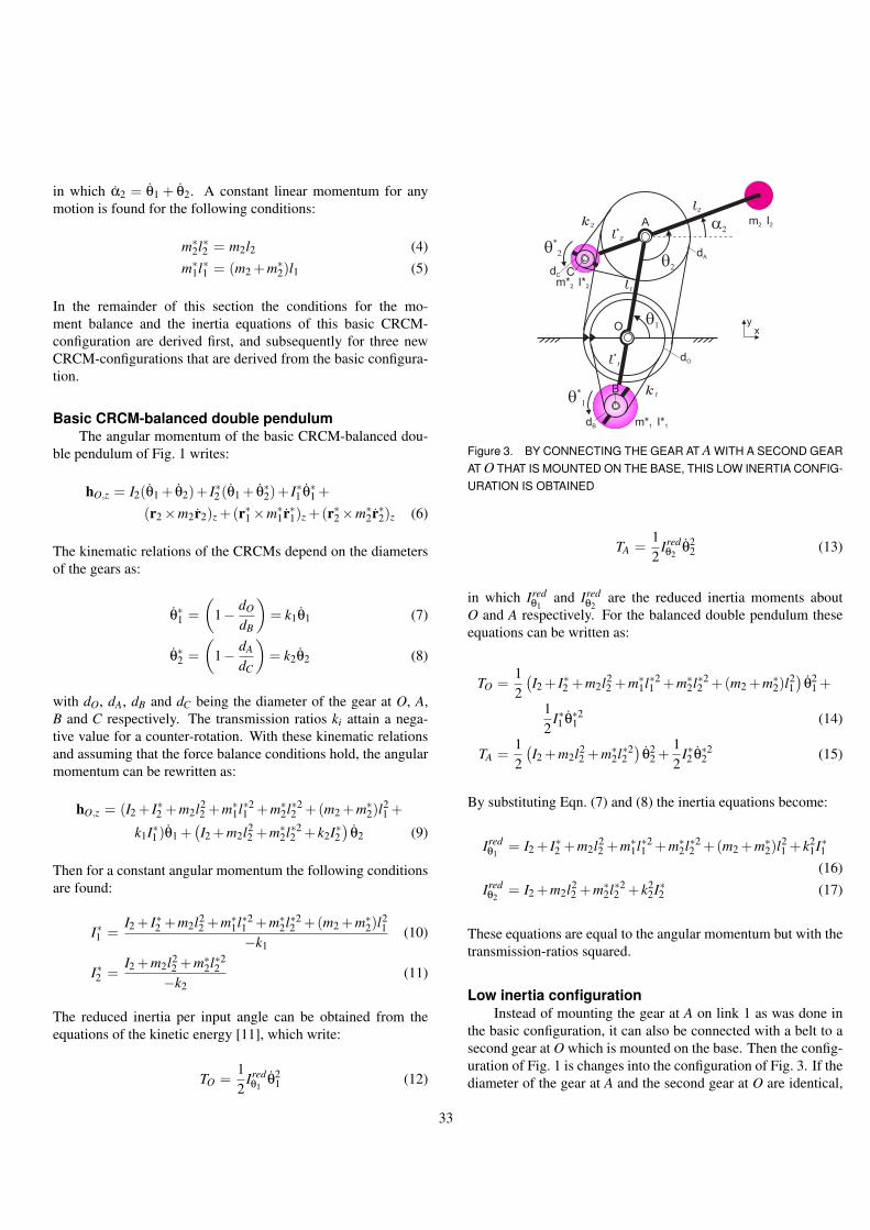
in which α2 = θ1 + θ2. A constant linear momentum for anymotion is found for the following conditions:
m∗2l∗2 = m2l2 (4)
m∗1l∗1 = (m2 +m∗
2)l1 (5)
In the remainder of this section the conditions for the mo-ment balance and the inertia equations of this basic CRCM-configuration are derived first, and subsequently for three newCRCM-configurations that are derived from the basic configura-tion.
Basic CRCM-balanced double pendulumThe angular momentum of the basic CRCM-balanced dou-
ble pendulum of Fig. 1 writes:
hO,z = I2(θ1 + θ2)+ I∗2 (θ1 + θ∗2)+ I∗1 θ∗1 +(r2×m2r2)z +(r∗1×m∗
1r∗1)z +(r∗2×m∗2r∗2)z (6)
The kinematic relations of the CRCMs depend on the diametersof the gears as:
θ∗1 =(
1− dO
dB
)= k1θ1 (7)
θ∗2 =(
1− dA
dC
)= k2θ2 (8)
with dO, dA, dB and dC being the diameter of the gear at O, A,B and C respectively. The transmission ratios ki attain a nega-tive value for a counter-rotation. With these kinematic relationsand assuming that the force balance conditions hold, the angularmomentum can be rewritten as:
hO,z = (I2 + I∗2 +m2l22 +m∗
1l∗21 +m∗
2l∗22 +(m2 +m∗
2)l21 +
k1I∗1 )θ1 +(I2 +m2l2
2 +m∗2l∗2
2 + k2I∗2)
θ2 (9)
Then for a constant angular momentum the following conditionsare found:
I∗1 =I2 + I∗2 +m2l2
2 +m∗1l∗2
1 +m∗2l∗2
2 +(m2 +m∗2)l
21
−k1(10)
I∗2 =I2 +m2l2
2 +m∗2l∗2
2−k2
(11)
The reduced inertia per input angle can be obtained from theequations of the kinetic energy [11], which write:
TO =12
Iredθ1
θ21 (12)
A
O
k1
k2
l1
m2 I2
l*
2
l*
1
a2
q2
l2
q1
xy
m*2 I*2
q*
2
m*1 I*1
q*
1
dO
dA
dC
dB
C
B
Figure 3. BY CONNECTING THE GEAR AT A WITH A SECOND GEARAT O THAT IS MOUNTED ON THE BASE, THIS LOW INERTIA CONFIG-URATION IS OBTAINED
TA =12
Iredθ2
θ22 (13)
in which Iredθ1
and Iredθ2
are the reduced inertia moments aboutO and A respectively. For the balanced double pendulum theseequations can be written as:
TO =12
(I2 + I∗2 +m2l2
2 +m∗1l∗2
1 +m∗2l∗2
2 +(m2 +m∗2)l
21)
θ21 +
12
I∗1 θ∗21 (14)
TA =12
(I2 +m2l2
2 +m∗2l∗2
2)
θ22 +
12
I∗2 θ∗22 (15)
By substituting Eqn. (7) and (8) the inertia equations become:
Iredθ1
= I2 + I∗2 +m2l22 +m∗
1l∗21 +m∗
2l∗22 +(m2 +m∗
2)l21 + k2
1I∗1(16)
Iredθ2
= I2 +m2l22 +m∗
2l∗22 + k2
2I∗2 (17)
These equations are equal to the angular momentum but with thetransmission-ratios squared.
Low inertia configurationInstead of mounting the gear at A on link 1 as was done in
the basic configuration, it can also be connected with a belt to asecond gear at O which is mounted on the base. Then the config-uration of Fig. 1 is changes into the configuration of Fig. 3. If thediameter of the gear at A and the second gear at O are identical,
33

the gear at A will only translate for any motion of link 1 and link2 and therefore is a parallel transmission. The advantage is thatin this case the CRCM m∗
2 balances the moment of link 2 for anymotion of the linkage while in the basic CRCM-configurationCRCM m∗
2 does not contribute to the moment balance for motionwith constant θ2.
Since the positions of the CRCMs are the same as for thebasic configuration, the linear momentum of this mechanism isequal to Eqn. (3). The angular momentum however can be writ-ten as follows:
hO,z = I2(θ1 + θ2)+ I∗2 θ∗2 + I∗1 θ∗1 +(r2×m2r2)z +(r∗1×m∗
1r∗1)z +(r∗2×m∗2r∗2)z (18)
in which θ∗1 is equal to Eqn. (7) and θ∗2 is written as:
θ∗2 = k2(θ1 + θ2) (19)
in which k2 is equal to that of Eqn. (8). With Eqn. (7) and (19)hO,z becomes:
hO,z = (I2 +m2l22 +m∗
1l∗21 +m∗
2l∗22 +
(m2 +m∗2)l
21 + k1I∗1 + k2I∗2 )θ1 +
(I2 +m2l22 +m∗
2l∗22 + k2I∗2 )θ2 (20)
For a constant angular momentum the following expressionsmust hold:
I∗1 =I2 +m2l2
2 +m∗1l∗2
1 +m∗2l∗2
2 +(m2 +m∗2)l
21 + k2I∗2
−k1(21)
I∗2 =I2 +m2l2
2 +m∗2l∗2
2−k2
(22)
Substituting Eqn. (22) into (21) for I∗2 results into:
I∗1 =m∗
1l∗21 +(m2 +m∗
2)l21
−k1(23)
Counter-inertia I∗1 in this principle is smaller than that of the basicCRCM-configuration in Eqn. (10). The equations of the reducedinertias of this configuration can be calculated as before and be-come:
Iredθ1
= (I2 +m2l22 +m∗
2l∗22 )(1− k2)+m∗
1l∗21 +(m2 +m∗
2)l21 + k2
1I∗1(24)
Iredθ2
= I2 +m2l22 +m∗
2l∗22 + k2
2I∗2 (25)
A
O
k1
k2
l1
m2 I2
l*
2
l*
1
m*2 I*2
m*1 I*1
a2
q2
l2
q1
xy
q*
2
dC C
B
dA,2
dA,1
dO
Figure 4. WITH THE TRANSMISSION RATIOS k1 AND k2, THE DOU-BLE PENDULUM CAN BE BALANCED WITH ONLY ONE CRCM
where Eqn. (22) was substituted in Eqn. (24). Since the CRCMm∗
2 in this configuration balances the moment of link 2 for anymotion of the mechanism, the reduced inertia about O is lowerthan that of the basic CRCM-configuration.
Balancing with only one CRCMDue to the appearance of transmission ratio k2 in Eqn. (21),
there exists a situation for which I∗1 can be fixed to link 1 andthe double pendulum is moment balanced with only one CRCM.Figure 4 shows a possible way in which, with respect to the con-figuration of Fig. 3, the gear at A is driven with a fixed gear atO and with transmission-ratio k1. m∗
1 in this case can be fixedto link 1 and is a counter-mass. The angular momentum of thismechanism writes:
hO,z = I2(θ1 + θ2)+ I∗2 θ∗2 + I∗1 θ1 +(r2×m2r2)z +(r∗1×m∗
1r∗1)z +(r∗2×m∗2r∗2)z (26)
in which the kinetic relation of θ∗2 depends on k1 and k2 and is:
θ∗2 =(
1− dO
dA,1
)(dA,2
dC
)θ1 +
(1− dA,2
dC
)θ2
= k1(1− k2)θ1 + k2θ2 (27)
with dO, dA,1, dA,2 and dC being the diameter of the gear at O, thesmall gear at A, the large gear at A and the gear at C respectively.By substituting Eqn. (27) into Eqn. (26) hO,z becomes:
hO,z = (I2 + I∗1 +m2l22 +m∗
1l∗21 +
34

A
O
k2
l1
m2 I2
l*
2
l*
1,b
m*1,b I*1,b
a2
q2
l2
q1
m*2 I*2
O
k1
l*
1,a
m*1,a I*1,a
q1 x
y+
q*
2 q*
1
dO,2 dO,1
dB,2 dB,2
a) b)
Figure 5. MOUNTING THE GEAR AT A TO LINK 2, THE DOUBLE PEN-DULUM CAN BE BALANCED WITH TWO CRCMs NEAR THE BASE.FIG. a AND b MUST BE ON TOP OF EACH OTHER WITH THE LINKSALIGNED AND SHARING THE SAME AXIS OF ROTATION AT O
m∗2l∗2
2 +(m2 +m∗2)l
21 + k1(1− k2)I∗2 )θ1 +
(I2 +m2l22 +m∗
2l∗22 + k2I∗2 )θ2 (28)
and the conditions for a constant angular momentum are:
I∗2 =I2 + I∗1 +m2l2
2 +m∗1l∗2
1 +m∗2l∗2
2 +(m2 +m∗2)l
21
−k1(1− k2)(29)
I∗2 =I2 +m2l2
2 +m∗2l∗2
2−k2
(30)
Substituting Eqn. (30) in (29) for k2 results into a condition fork1:
k1 =− I2 + I∗1 +m2l22 +m∗
1l∗21 +m∗
2l∗22 +(m2 +m∗
2)l21
I2 + I∗2 +m2l22 +m∗
2l∗22
(31)
and the equations of the reduced inertias are written by:
Iredθ1
= (I2 + I∗1 +m2l22 +m∗
1l∗21 +m∗
2l∗22 +
(m2 +m∗2)l
21 + k2
1(1− k2)2I∗2 (32)Iredθ2
= I2 +m2l22 +m∗
2l∗22 + k2
2I∗2 (33)
Only CRCMs near the baseInstead of mounting the gear at A at link 1 as in the basic
CRCM-configuration or connecting it to the base as in the con-figurations of Fig. 3 and 4, it is also possible to connect it to link
2. Then the motion of link 2 can be transmitted to the base. Theconfiguration then becomes as in Fig. 5.
Still there are two CRCMs m∗1,a and m∗
1,b, however both arelocated at link 1. For clarity, they are shown next to one another.m∗
1,a and m∗1,b do not need to be at the same location and they both
contribute to the force balance of the mechanism about O. If thesum of m∗
1,a and m∗1,b is equal to m∗
1 and the sum of l∗1,a and l∗1,b isequal to l∗1 of the previous configurations then the force balanceis maintained for the conditions of Eqn. (4) and (5).
For the moment balance of link 2, in Fig. 5a a gear mountedon link 2 at A drives a gear at O with a parallel transmission(equal gear diameters) and the gear at O has m∗
1,b counter-rotatewith respect to link 2. A second gear at O (Fig. 5b) is connectedwith a belt to m∗
1,a, which balances the moment of the mecha-nism about O. The angular momentum of this mechanism can bewritten as:
hO,z = (I2 + I∗2 )(θ1 + θ2)+ I∗1,b(θ1 + θ∗2)+ I∗1,aθ∗1 +(r2×m2r2)z +(r∗1×m∗
1r∗1)z +(r∗2×m∗2r∗2)z (34)
The kinematic relations of θ∗1 and θ∗2 are:
θ∗1 =(
1− dO,1
dB,1
)= k1θ1 (35)
θ∗2 =(
1− dO,2
dB,2
)= k2θ2 (36)
with dO,1, dO,2, dB,1 and dB,2 being the diameter of the gear atO and B for link 1 and link 2 respectively. With these equationshO,z becomes:
hO,z = (I2 + I∗2 + I∗1,b +m2l22 +m∗
1l∗21 +
m∗2l∗2
2 +(m2 +m∗2)l
21 + k1I∗1,a)θ1 +
(I2 + I∗2 +m2l2
2 +m∗2l∗2
2 + k2I∗1,b)
θ2 (37)
Hence the mechanism is moment balanced if:
I∗1,a =I2 + I∗2 + I∗1,b +m2l2
2 +m∗1l∗2
1 +m∗2l∗2
2 +(m2 +m∗2)l
21
−k1(38)
I∗1,b =I2 + I∗2 +m2l2
2 +m∗2l∗2
2−k2
(39)
Substituting Eqn. (39) in (38) for I∗1,b results into:
I∗1,a =(I2 + I∗2 +m2l2
2 +m∗2l∗2
2 )(1− 1k2
)+m∗1l∗2
1 +(m2 +m∗2)l
21
−k1(40)
35

A
q2
q1
O
Figure 6. 2-DOF BALANCED PARALLEL MECHANISM OBTAINED BYCOMBINATION OF TWO CRCM-BALANCED DOUBLE PENDULA
The equations for the reduced inertia become:
Iredθ1
= I2 + I∗2 + I∗1,b +m2l22 +m∗
1l∗21 +
m∗2l∗2
2 +(m2 +m∗2)l
21 + k2
1I∗1,a (41)
Iredθ2
= I2 + I∗2 +m2l22 +m∗
2l∗22 + k2
2I∗1,b (42)
Evaluation of the different configurationsThe inertia of the CRCMs and the inertia equations depend
on the choice of the transmission ratios. For increasing transmis-sion ratios the inertia of the CRCMs decreases proportionally,but the equations for the reduced inertia increase quickly sincethe transmission ratios appear squared.
Practically, the advantage of the configuration of Fig. 3 is itslow inertia since also for motion about O, the moment of link 2is balanced by CRCM m∗
2. The advantage of the configuration ofFig. 4 is that only one CRCM is necessary for the moment bal-ance of the complete mechanism. The configuration of Fig. 5 isuseful since having CRCMs only near the base allows a compactconstruction of a balanced machine.
The inertia equations of the configuration of Fig. 4 can bereduced by combining it with Fig. 3 where m∗
1 in Fig. 3 is drivenby a parallel transmission (k1 = 0) and does never rotate. m∗
2 thenis used for the moment balance of both degrees of freedom as inFig. 4. The result is that the term I∗1 drops from Eqn. (26), (28),(29), (31) and (32). It is evident that for a low inertia the counter-masses should not rotate with respect to the base, besides what isnecessary to maintain the moment balance.
CRCM-BALANCED 2-DOF PARALLEL MECHANISMSIn this section three new CRCM-balanced 2-DOF parallel
mechanisms are synthesized by using the CRCM-balanced dou-ble pendulum of Fig. 1. It is shown that the balancing conditionsand the inertia equations for these parallel mechanisms can bederived quickly.
A
O
k1
l1
m2 I2
l*
2
l*
1
m*2,1 I*2,1
m*1,1 I*1,1
a2
q2
l2
l2
l*
2
l1
l*
1
m*2,2 I*2,2
k2
m*1,2 I*1,2
xy
a1
q*
1
q*
2
q1
Figure 7. ONLY 2 CRCMs ARE NEEDED TO BALANCE THE MOMENT,THE OTHER TWO REMAIN AS CMs [12]
A
O
q2
q1 Idler Loop
Figure 8. BALANCED 2-DOF PARALLEL MECHANISM BY COMBINA-TION OF A BALANCED DOUBLE PENDULUM AND AN IDLER LOOP
Any combination of one or more balanced double (or single)pendula results into a balanced mechanism. Therefore two dou-ble pendula balanced as in Fig. 1 can be combined such that theirorigin is at the same location and they form the parallel mech-anism of Fig. 6. The endpoint of each double pendulum doesnot need to coincide but can be anywhere as long as the linksremain parallel. The mass at the endpoint and its inertia can bebalanced by both links or by only one of them. The other thenstill is necessary to balance the mass and inertia of the link itself.
Since the angular velocity of parallel links is equal, for themoment balance of two parallel links only one CRCM is nec-essary. This means there are only two CRCMs necessary whichboth can be constructed compact near the base as shown in Fig. 7.This is a configuration described in [12]. The former CRCMs be-come fixed counter-masses.
It is also possible to derive this parallel mechanism by com-bination of an idler loop [13] and a CRCM-balanced double pen-
36
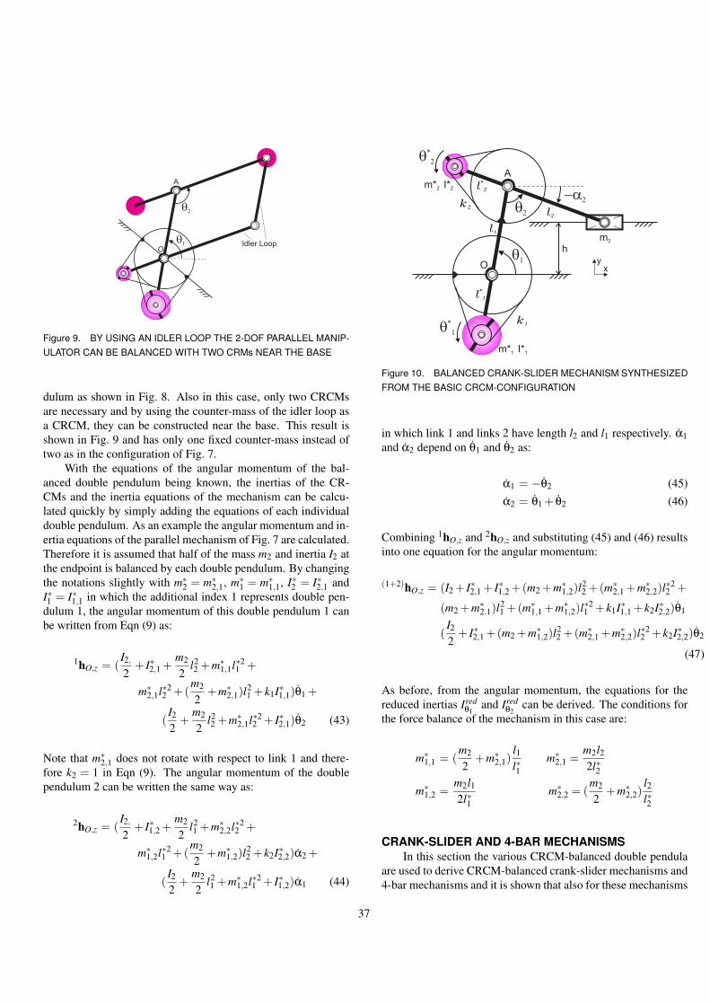
A
O
q2
q1 Idler Loop
Figure 9. BY USING AN IDLER LOOP THE 2-DOF PARALLEL MANIP-ULATOR CAN BE BALANCED WITH TWO CRMs NEAR THE BASE
dulum as shown in Fig. 8. Also in this case, only two CRCMsare necessary and by using the counter-mass of the idler loop asa CRCM, they can be constructed near the base. This result isshown in Fig. 9 and has only one fixed counter-mass instead oftwo as in the configuration of Fig. 7.
With the equations of the angular momentum of the bal-anced double pendulum being known, the inertias of the CR-CMs and the inertia equations of the mechanism can be calcu-lated quickly by simply adding the equations of each individualdouble pendulum. As an example the angular momentum and in-ertia equations of the parallel mechanism of Fig. 7 are calculated.Therefore it is assumed that half of the mass m2 and inertia I2 atthe endpoint is balanced by each double pendulum. By changingthe notations slightly with m∗
2 = m∗2,1, m∗
1 = m∗1,1, I∗2 = I∗2,1 and
I∗1 = I∗1,1 in which the additional index 1 represents double pen-dulum 1, the angular momentum of this double pendulum 1 canbe written from Eqn (9) as:
1hO,z = (I2,
2+ I∗2,1 +
m2
2l22 +m∗
1,1l∗21 +
m∗2,1l∗2
2 +(m2
2+m∗
2,1)l21 + k1I∗1,1)θ1 +
(I2
2+
m2
2l22 +m∗
2,1l∗22 + I∗2,1)θ2 (43)
Note that m∗2,1 does not rotate with respect to link 1 and there-
fore k2 = 1 in Eqn (9). The angular momentum of the doublependulum 2 can be written the same way as:
2hO,z = (I2,
2+ I∗1,2 +
m2
2l21 +m∗
2,2l∗22 +
m∗1,2l∗2
1 +(m2
2+m∗
1,2)l22 + k2I∗2,2)α2 +
(I2
2+
m2
2l21 +m∗
1,2l∗21 + I∗1,2)α1 (44)
A
O
k1
k2
l1
m2
l*
2
l*
1
m*2 I*2
m*1 I*1
-a2
q2 l
2
q1
xy
k2
h
q*
2
q*
1
Figure 10. BALANCED CRANK-SLIDER MECHANISM SYNTHESIZEDFROM THE BASIC CRCM-CONFIGURATION
in which link 1 and links 2 have length l2 and l1 respectively. α1and α2 depend on θ1 and θ2 as:
α1 = −θ2 (45)α2 = θ1 + θ2 (46)
Combining 1hO,z and 2hO,z and substituting (45) and (46) resultsinto one equation for the angular momentum:
(1+2)hO,z = (I2 + I∗2,1 + I∗1,2 +(m2 +m∗1,2)l
22 +(m∗
2,1 +m∗2,2)l
∗22 +
(m2 +m∗2,1)l
21 +(m∗
1,1 +m∗1,2)l
∗21 + k1I∗1,1 + k2I∗2,2)θ1
(I2
2+ I∗2,1 +(m2 +m∗
1,2)l22 +(m∗
2,1 +m∗2,2)l
∗22 + k2I∗2,2)θ2
(47)
As before, from the angular momentum, the equations for thereduced inertias Ired
θ1and Ired
θ2can be derived. The conditions for
the force balance of the mechanism in this case are:
m∗1,1 = (
m2
2+m∗
2,1)l1l∗1
m∗2,1 =
m2l22l∗2
m∗1,2 =
m2l12l∗1
m∗2,2 = (
m2
2+m∗
2,2)l2l∗2
CRANK-SLIDER AND 4-BAR MECHANISMSIn this section the various CRCM-balanced double pendula
are used to derive CRCM-balanced crank-slider mechanisms and4-bar mechanisms and it is shown that also for these mechanisms
37

the balancing conditions and the inertia equations can be derivedquickly.
By restricting the motion of the endpoint of the balanceddouble pendulum to move along a specific trajectory, CRCM-balanced crank-slider mechanisms can be obtained from theCRCM-balanced double pendula of Fig. 1, 3, 4 and 5. For threeconfigurations the CRCM-balanced crank-slider mechanisms areshown in Fig. 10, 11 and 12 for which the slider moves along astraight trajectory with offset h. The slider mass then does notrotate and a CRCM is only needed for the moment balance of thelink connected to the slider.
The advantages of each CRCM-configuration remain if theconfiguration is used as crank-slider mechanisms. Important fea-tures with respect to many other possible balancing configura-tions are that there are no transmission irregularities or singulari-ties and the mechanism can fully rotate (by suitable link lengths).
Also for the crank-slider mechanisms the conditions for theforce and moment balance and the inertia equations can be ob-tained easily. The procedure is equal to that of the parallel mech-anisms, first writing the angular momentum of the double pendu-lum, which is known, than substituting the kinematic relations.In these 1-DOF crank-slider mechanisms, θ2 depends on θ1. Thisrelation is easy to find from the second equation of r2 and itsderivative:
r2,y = l1 sinθ1 + l2 sinα2 = h (48)r2,y = l1θ1 cosθ1 + l2α2 cosα2 = 0 (49)
With α2 = θ1 + θ2, θ2 can then be written as:
θ2 =(−l1 cosθ1
l2 cosα2−1
)θ1 (50)
with
α2 = sin−1(
h− l1 sinθ1
l2
)(51)
As an example the configuration of Fig. 12 is taken for which theangular momentum writes from Eqn. (37):
hO,z = (I∗2 + I∗1,b +m2l22 +m∗
1l∗21 +
m∗2l∗2
2 +(m2 +m∗2)l
21 + k1I∗1,a)θ1 +
(I∗2 +m2l22 +m∗
2l∗22 + k2I∗1,b)θ2 (52)
Substituting the kinematic relations of Eqn. (50) and (51) thenresults into:
hO,z = (I∗2 + I∗1,b +m2l22 +m∗
1l∗21 +
O
k2
l1
m2
l*
2
-a2
q1
xy
h
k1
l*
1
A
q2
m*2 I*2
m*1 I*1
q*
2
k2
l2
Figure 11. BALANCED CRANK-SLIDER MECHANISM SYNTHESIZEDFROM THE CRCM-CONFIGURATION WITH A SINGLE CRCM
O
l*
2
l*
1,b
q1
O
l*
1,a
q1 x
y
+
A
l1
m2
m*2 I*2
-a2
q2 l
2
k2
k1
m*1,a I*1,a
h
q*
1,b q*
1,am*1,b I*1,b
a) b)
Figure 12. BALANCED CRANK-SLIDER MECHANISM SYNTHESIZEDFROM THE CRCM-CONFIGURATION WITH TWO CRCMs NEAR THEBASE
m∗2l∗2
2 +(m2 +m∗2)l
21 + k1I∗1,a +
(I∗2 +m2l22 +m∗
2l∗22 + k2I∗1,b)(
−l1 cosθ1
l2 cosα2−1))θ1 (53)
The single equation of the reduced inertia now is dependent onthe position of the mechanism. This equation also holds foran unconstrained balanced double pendulum moving along thesame trajectory, although than there are two input angles whicheach have a constant reduced inertia.
Another balanced slider mechanism can be derived fromthe parallel mechanism of Fig. 7. If the endpoint of this par-allel mechanism moves along a straight line through the originas shown in Fig. 13, than the two CRCMs can become fixedcounter-masses. Half of the mass m2 (and half of I2 if not a
38

A
O
l*
2
l*
1
l1
l*
1
l2
l*
2
m2
l1
l2
Figure 13. 1-DOF CRANK-SLIDER MECHANISM WITHOUT CRCMsOBTAINED BY RESTRICTING THE MOTION OF THE ENDPOINT OFTHE 2-DOF PARALLEL MANIPULATOR
slider) then is balanced by each link that is attached to it. Theinertia and length of these links than must be equal and also thelinks attached to the origin must have equal inertia and lengthby which they become moment balanced sets. With these condi-tions it is also possible to have the length and inertia of the linksattached to the slider be different from the length and inertia ofthe links attached to the origin.
Berestov in [7] showed a planar 4-bar mechanism balancedby CRCMs driven by inner gears. This mechanism can be re-garded as a combination of a balanced single and a balanceddouble pendulum, shown with belt driven CRCMs in Fig. 14.Also for 4-bar mechanisms, the different CRCM-configurationsare applicable just as the substitution of the well-known kine-matic relations into the inertia equations of the double and singlependulum to obtain the inertia about one of the links. This meansthat with the equations for the double and single pendulum andthe kinematic relations the inertia of any 4-bar mechanism canbe written down easily.
Special is the case for which the 4-bar linkage becomes aparallelogram. From Fig. 9 and assuming the link between Oand A to be fixed with the base, the resulting parallelogram canbe balanced as in Fig. 15. Only one CRCM and one counter-mass are necessary. If the COM of the coupler link is at oneof the joints, then it is even possible to balance the completemechanism with solely a CRCM.
3-DOF PARALLEL MECHANISMSAlso CRCM-balanced 3-DOF planar and spatial mecha-
nisms can be synthesized by combining CRCM-balanced double
q1 q
2
q3
Figure 14. BALANCED 4-BAR MECHANISM BY COMBINATION OF ACRCM-BALANCED DOUBLE AND A CRCM-BALANCED SINGLE PEN-DULUM
q1
OA
Figure 15. BALANCED 1-DOF PARALLELOGRAM DERIVED BY FIX-ING LINK OA OF THE 2-DOF PARALLEL MANIPULATOR WITH IDLERLINK
q1
q2
q3
Figure 16. CRCM-BALANCED PLANAR 3-RRR PARALLEL MANIPU-LATOR BY COMBINING THREE CRCM-BALANCED DOUBLE PEN-DULA WITH EACH ONE CRCM
39
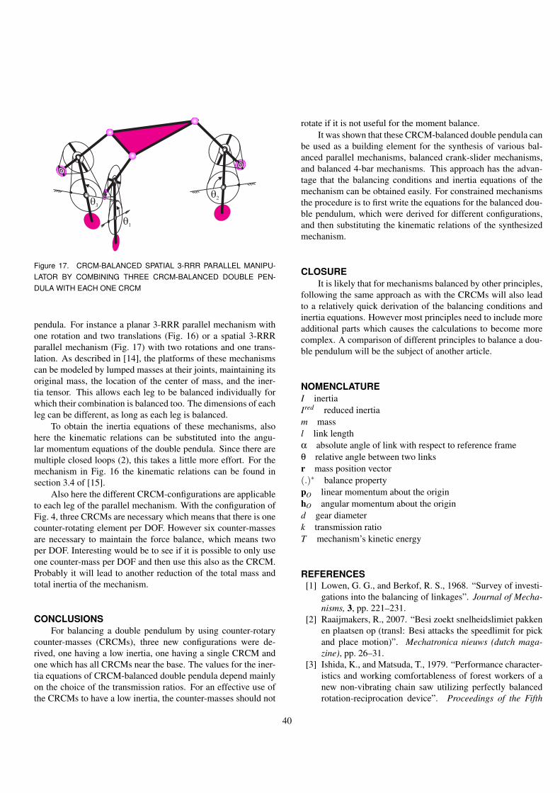
q3
q2
q1
Figure 17. CRCM-BALANCED SPATIAL 3-RRR PARALLEL MANIPU-LATOR BY COMBINING THREE CRCM-BALANCED DOUBLE PEN-DULA WITH EACH ONE CRCM
pendula. For instance a planar 3-RRR parallel mechanism withone rotation and two translations (Fig. 16) or a spatial 3-RRRparallel mechanism (Fig. 17) with two rotations and one trans-lation. As described in [14], the platforms of these mechanismscan be modeled by lumped masses at their joints, maintaining itsoriginal mass, the location of the center of mass, and the iner-tia tensor. This allows each leg to be balanced individually forwhich their combination is balanced too. The dimensions of eachleg can be different, as long as each leg is balanced.
To obtain the inertia equations of these mechanisms, alsohere the kinematic relations can be substituted into the angu-lar momentum equations of the double pendula. Since there aremultiple closed loops (2), this takes a little more effort. For themechanism in Fig. 16 the kinematic relations can be found insection 3.4 of [15].
Also here the different CRCM-configurations are applicableto each leg of the parallel mechanism. With the configuration ofFig. 4, three CRCMs are necessary which means that there is onecounter-rotating element per DOF. However six counter-massesare necessary to maintain the force balance, which means twoper DOF. Interesting would be to see if it is possible to only useone counter-mass per DOF and then use this also as the CRCM.Probably it will lead to another reduction of the total mass andtotal inertia of the mechanism.
CONCLUSIONSFor balancing a double pendulum by using counter-rotary
counter-masses (CRCMs), three new configurations were de-rived, one having a low inertia, one having a single CRCM andone which has all CRCMs near the base. The values for the iner-tia equations of CRCM-balanced double pendula depend mainlyon the choice of the transmission ratios. For an effective use ofthe CRCMs to have a low inertia, the counter-masses should not
rotate if it is not useful for the moment balance.It was shown that these CRCM-balanced double pendula can
be used as a building element for the synthesis of various bal-anced parallel mechanisms, balanced crank-slider mechanisms,and balanced 4-bar mechanisms. This approach has the advan-tage that the balancing conditions and inertia equations of themechanism can be obtained easily. For constrained mechanismsthe procedure is to first write the equations for the balanced dou-ble pendulum, which were derived for different configurations,and then substituting the kinematic relations of the synthesizedmechanism.
CLOSUREIt is likely that for mechanisms balanced by other principles,
following the same approach as with the CRCMs will also leadto a relatively quick derivation of the balancing conditions andinertia equations. However most principles need to include moreadditional parts which causes the calculations to become morecomplex. A comparison of different principles to balance a dou-ble pendulum will be the subject of another article.
NOMENCLATUREI inertiaIred reduced inertiam massl link lengthα absolute angle of link with respect to reference frameθ relative angle between two linksr mass position vector(.)∗ balance propertypO linear momentum about the originhO angular momentum about the origind gear diameterk transmission ratioT mechanism’s kinetic energy
REFERENCES[1] Lowen, G. G., and Berkof, R. S., 1968. “Survey of investi-
gations into the balancing of linkages”. Journal of Mecha-nisms, 3, pp. 221–231.
[2] Raaijmakers, R., 2007. “Besi zoekt snelheidslimiet pakkenen plaatsen op (transl: Besi attacks the speedlimit for pickand place motion)”. Mechatronica nieuws (dutch maga-zine), pp. 26–31.
[3] Ishida, K., and Matsuda, T., 1979. “Performance character-istics and working comfortableness of forest workers of anew non-vibrating chain saw utilizing perfectly balancedrotation-reciprocation device”. Proceedings of the Fifth
40

World Congress of Theory of Machines and Mechanisms,ASME, pp. 951–954.
[4] Brown, G. W., 1987. Suspension system for supportingand conveying equipment, such as a camera, patent number:US-4710819.
[5] Dresig, H., Rockhausen, L., and Naake, S., 1992. “Balanc-ing conditions for planar mechanisms”. Flexible Mecha-nisms, Dynamics and Analysis, 47, pp. 67–73.
[6] Kochev, I. S., 2000. “General theory of complete shakingmoment balancing of planar linkages: A critical review”.Mechanism and Machine Theory, 35, pp. 1501–1514.
[7] Berestov, L. V., 1975. “Full dynamic balancing of ar-ticulated four-link chain”. Izv. Vyssh. Uchebn. Zaved.-Mashinostroenic, 11, pp. 62–65. (Russian).
[8] Herder, J. L., and Gosselin, C. M., 2004. “A counter-rotarycounterweight (CRCW) for light-weight dynamic balanc-ing”. Proceedings of DETC 2004, ASME,(DETC2004-57246).
[9] Van der Wijk, V., Herder, J. L., and Demeulenaere, B.,2008. “Comparison of various dynamic balancing prin-ciples regarding additional mass and additional inertia”.MSc-Thesis TU-Delft.
[10] Van der Wijk, V., and Herder, J. L., 2008. “Comparativeanalysis and optimization for low-mass and low-inertia dy-namic balancing of a 1-DOF rotatable link balanced by acounter-rotary counter-mass”. MSc-Thesis TU-Delft.
[11] VDI2149, 1999. “Blatt 1: Getriebedynamik-starrkorpermechanismen (dynamics of mechanisms-rigid body mech-anisms)”. Verein Deutscher Ingenieure - Richtlinien.
[12] Menschaar, H. F., Ariens, A. B., Herder, J. L., and Bakker,B. M., 2006. Five-bar mechanism with dynamic balanc-ing means and method for dynamically balancing a five-barmechanism, patent number: W0 2006/080846.
[13] Bagci, C., 1982. “Complete shaking force and shaking mo-ment balancing of link mechanisms using balancing idlerloops”. Transactions ASME, Journal of Mechanical De-sign, 104(2), pp. 482–493.
[14] Wu, Y., and Gosselin, C. M., 2007. “On the dynamicbalancing of multi-dof parallel mechanisms with multi-ple legs”. Journal of Mechanical Design, 129, February,pp. 234–238.
[15] Tsai, L.-W., 1999. Robot Analysis. John Wiley and Sons,Inc.
41

CHAPTER 5-
COMPLETE DYNAMIC BALANCING OFCRANK-SLIDER MECHANISMS WITHOUT
ADDITIONAL ELEMENTS AT THE COUPLERLINK FOR LOW-MASS AND LOW-INERTIA
DYNAMIC BALANCING
V. van der Wijk, J.L. HerderFaculty of Mechanical Engineering, Delft University of Technology
To be submitted to Mechanism and Machine Theory
42
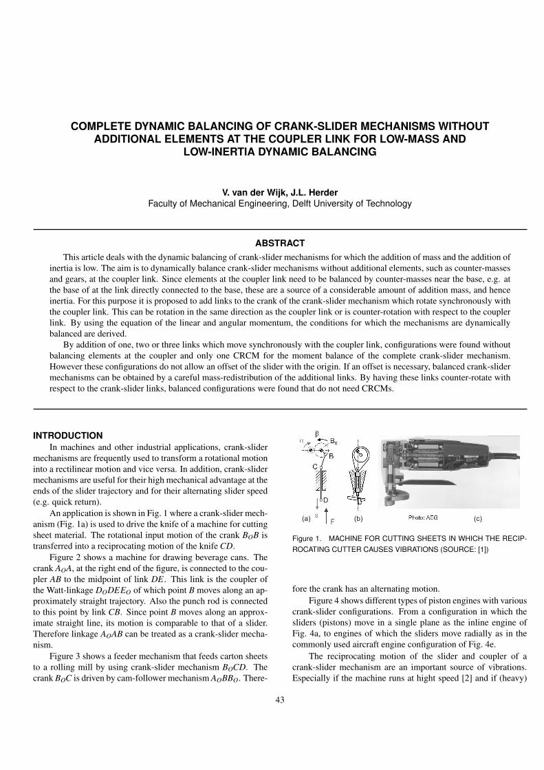
COMPLETE DYNAMIC BALANCING OF CRANK-SLIDER MECHANISMS WITHOUTADDITIONAL ELEMENTS AT THE COUPLER LINK FOR LOW-MASS AND
LOW-INERTIA DYNAMIC BALANCING
V. van der Wijk, J.L. HerderFaculty of Mechanical Engineering, Delft University of Technology
ABSTRACTThis article deals with the dynamic balancing of crank-slider mechanisms for which the addition of mass and the addition of
inertia is low. The aim is to dynamically balance crank-slider mechanisms without additional elements, such as counter-massesand gears, at the coupler link. Since elements at the coupler link need to be balanced by counter-masses near the base, e.g. atthe base of at the link directly connected to the base, these are a source of a considerable amount of addition mass, and henceinertia. For this purpose it is proposed to add links to the crank of the crank-slider mechanism which rotate synchronously withthe coupler link. This can be rotation in the same direction as the coupler link or is counter-rotation with respect to the couplerlink. By using the equation of the linear and angular momentum, the conditions for which the mechanisms are dynamicallybalanced are derived.
By addition of one, two or three links which move synchronously with the coupler link, configurations were found withoutbalancing elements at the coupler and only one CRCM for the moment balance of the complete crank-slider mechanism.However these configurations do not allow an offset of the slider with the origin. If an offset is necessary, balanced crank-slidermechanisms can be obtained by a careful mass-redistribution of the additional links. By having these links counter-rotate withrespect to the crank-slider links, balanced configurations were found that do not need CRCMs.
INTRODUCTIONIn machines and other industrial applications, crank-slider
mechanisms are frequently used to transform a rotational motioninto a rectilinear motion and vice versa. In addition, crank-slidermechanisms are useful for their high mechanical advantage at theends of the slider trajectory and for their alternating slider speed(e.g. quick return).
An application is shown in Fig. 1 where a crank-slider mech-anism (Fig. 1a) is used to drive the knife of a machine for cuttingsheet material. The rotational input motion of the crank BOB istransferred into a reciprocating motion of the knife CD.
Figure 2 shows a machine for drawing beverage cans. Thecrank AOA, at the right end of the figure, is connected to the cou-pler AB to the midpoint of link DE. This link is the coupler ofthe Watt-linkage DODEEO of which point B moves along an ap-proximately straight trajectory. Also the punch rod is connectedto this point by link CB. Since point B moves along an approx-imate straight line, its motion is comparable to that of a slider.Therefore linkage AOAB can be treated as a crank-slider mecha-nism.
Figure 3 shows a feeder mechanism that feeds carton sheetsto a rolling mill by using crank-slider mechanism BOCD. Thecrank BOC is driven by cam-follower mechanism AOBBO. There-
D
(a) (b) (c)
Figure 1. MACHINE FOR CUTTING SHEETS IN WHICH THE RECIP-ROCATING CUTTER CAUSES VIBRATIONS (SOURCE: [1])
fore the crank has an alternating motion.Figure 4 shows different types of piston engines with various
crank-slider configurations. From a configuration in which thesliders (pistons) move in a single plane as the inline engine ofFig. 4a, to engines of which the sliders move radially as in thecommonly used aircraft engine configuration of Fig. 4e.
The reciprocating motion of the slider and coupler of acrank-slider mechanism are an important source of vibrations.Especially if the machine runs at hight speed [2] and if (heavy)
43

tools (e.g. saw, punch rod, mould) or other masses are mountedon the slider or the coupler. A vibrating cutting machine as inFig. 1 can induce injuries to a person’s hand, while vibrating pro-duction machines such as in Fig. 2 and 3 can lead to productioninaccuracies. For instance in feeder mechanism, vibrations couldcause the carton sheets to get stuck, which leads to a standstill ofthe machine for reparation. With complete dynamic balancing,these vibrations are eliminated [3]. Dynamic balancing of crank-slider mechanisms therefore has been an interesting topic alreadyfor a long time.
The crank-slider mechanisms which were dynamically bal-anced in [4] have the disadvantage that counter-masses (CMs)have to be added to the coupler link which have to be balancedby other CMs near the base. Due to this a considerable amountof addition mass, and indirectly inertia, is needed while if thecounter-masses are near the base, i.e. at the base or at a linkdirectly connected to the base, the addition of mass is muchsmaller [5]. In addition, often in practice it is not possible tohave counter-masses and gears at the coupler link since the spacein which the mechanism has to move is small, for example incombustion engines.
The aim is to completely dynamically balance crank-slider mechanisms without additional elements, such as counter-masses and gears, at the coupler link.
For this purpose it is proposed to add links to the crank ofthe crank-slider mechanism which rotate synchronously with thecoupler link. These additional link then rotate with the same ro-tation speed, in the same direction as the coupler link or counter-rotating with respect to the coupler link. It is expected thathereby the additional links will dynamically balance the couplerlink and only balancing elements have to be added to the crankor at the base to balance the crank and the slider.
In [5] and [6] an overview of many balanced crank-sliderconfigurations is given. Most of them are however partially bal-anced and some assume a constant rotational velocity of thecrank. Only a few are completely force and moment balancedwhich is achieved by adding balancing elements to the coupler,or by adding axial- and mirror-symmetric duplicates of the initialmechanism to the same base.
All crank-slider mechanism in this article however are com-pletely dynamically balanced. For the easy of notation, a com-pletely dynamically balanced mechanism is referred to as a bal-anced mechanism.
This article specifically deals with crank-slider mechanismsin which the slider moves along a line. However there exista wide variety of crank-slider mechanisms of which the slidermoves along a curved (polynomial) trajectory []. It will be notedif the balanced crank-slider mechanisms in this chapter are suit-able for curved trajectories too, whereby the slider inertia is nottaken into account. Although for some shapes of the slider tra-jectory it is possible to balance the moment of the slider easily,in general it can be quite difficult. This however goes beyond the
Figure 2. DRAWING MACHINE FOR BEVERAGE CANS DRIVEN BYAN APPROXIMATE CRANK-SLIDER (SOURCE: [7])
Figure 3. FEEDER MECHANISM FOR ROLLING MILL DRIVEN BY ACAM-FOLLOWER CRANK-SLIDER COMBINATION (SOURCE: [7])
scope of this chapter.First the crank-slider mechanisms of [4] are recapitulated.
These have both force balancing and moment balancing elementsat their coupler link. Then a configuration with one additionalsynchronously rotating link is treated in which the elements nec-essary for the moment balance are eliminated from the couplerlink. By adding two synchronously rotating links to the crank-slider mechanism and using them as counter-rotating elements,configurations are obtained in which no other moment balancingelements are needed. In the last section, three synchronously ro-tating links are added to the crank-slider mechanism for whichall CMs are at the base.
CRANK-SLIDER WITHOUT ADDITIONAL LINKSThe balanced crank-slider mechanisms of Fig. 5, 6 and 7
were found in [4] by constraining the motion of the endpoint of a
44

a) Inline engine
b) Boxer engine
c) V-engine
d) W-engine
e) Radial engine f) Opposed-piston engine
Figure 4. VARIOUS TYPES OF PISTON ENGINES (SOURCE: [8])
A
O
k1
k2
l1
m2
l*
2
l*
1
m*2 I*2
m*1 I*1
-a2
q2 l
2
q1
xy
k2
h
q*
2
q*
1
Figure 5. BALANCED CRANK-SLIDER MECHANISM OF WHICHEACH LINK IS BALANCED BY A CRCM
O
k2
l1
m2
l*
2
-a2
q1
xy
h
k1
l*
1
A
q2
m*2 I*2
m*1 I*1
q*
2
k2
l2
Figure 6. BALANCED CRANK-SLIDER MECHANISM WITH ONECRCM FOR THE BALANCE OF THE COMPLETE MECHANISM
balanced double pendulum to move along a rectilinear trajectorywith offset h. The crank-slider mechanisms in Fig. 5 consistsof a crank with length l1, a coupler with length l2 and a sliderwith mass m2. The coupler is force balanced with respect to Aby CM m∗
2 and both links are force balanced with respect to theorigin O by CM m∗
1. The moment of the coupler is balancedby counter-rotating the CM m∗
2 which has an inertia I∗2 . This isaccomplished by a belt transmission between a gear at the CMand a gear at A that is mounted on the crank. This CM than iscalled a counter-rotary counter-mass (CRCM). Equivalently, forthe moment balance of the complete mechanism about O, CMm∗
1 with inertia I∗1 is driven by a belt such that it counter-rotateswith respect to the crank and therefore is a CRCM too.
Fig. 6 and 7 show two alternative configurations. With adifferent transmission of the belts, in Fig. 6 only one counter-rotating is needed for the moment balance of the complete mech-anism. In Fig. 7 the two counter-rotating elements are positionedat the crank, for clarity drawn next to one another.
These crank-slider mechanisms are balanced for any motionand hence suitable for any shape of slider trajectory. They allhave at least a gear and a CM at their coupler. As can be seenin the figures, a considerably large empty surrounding is neededfor their motion. In addition, if the crank-slider mechanisms arelarge, the dimensions of the transmissions become easily largetoo.
MOMENT BALANCING BY ONE CRCM NEAR THEBASE
A first step to reduce the number of additional elements tothe coupler, is by removing the elements that are needed for themoment balance. Therefore it is proposed to add a link to the
45

O
l*
2
l*
1,b
q1
O
l*
1,a
q1 x
y
+
A
l1
m2
m*2 I*2
-a2
q2 l
2
k2
k1
m*1,a I*1,a
h
q*
1,b q*
1,am*1,b I*1,b
Figure 7. BALANCED CRANK-SLIDER MECHANISM WHERE THETWO CRCMs ARE PLACED AT THE CRANK
O
k2
l1
m2
l*
2m*2 I*2
-a2
l2
q1
xy
h2
k1
k2
l*
1
m*3 I*3
A
q2
m*4 I*4
l*
3
l*
4
h3
-a2 B
a*
2
Figure 8. CRANK-SLIDER MECHANISM BALANCED WITH ONECRCM AT THE BASE AND ONE LINK THAT IS PARALLEL TO THECOUPLER; NO ELEMENTS FOR THE MOMENT BALANCE HAVE TOBE ADDED TO THE COUPLER; THE PART BELOW THE ORIGIN CANBE SCALED
crank-slider mechanism that is connected to the crank en rotatessynchronously with the coupler. Figure 8 shows such a config-uration in which the additional link is connected to the crank atB. This link replaces the CM m∗
1 in Fig. 5, 6 and 7 and is parallelto the coupler. It has a CRCM m∗
3 with inertia I∗3 and a counter-mass m∗
4 with inertia I∗4 . To keep the link parallel to the coupler,CRCM m∗
3 is connected to a slider that slides at an offset h3. Theconditions for which these links are parallel then follow from thesimilarity of triangles and are:
l2l1
=l∗3l∗1
h2
l1=
h3
l∗1(1)
The advantage of this configuration is that balancing linkage l∗1 -l∗3 can be scaled to any size, hence be much smaller than theinitial linkage l1-l2. Besides, the CRCM and gears are placedaway from the workspace.
The CRCM m∗3 is driven in the same way as the CRCM in
Fig. 6, but here the transmission is placed at the balancing linkageinstead of the initial linkage. A gear mounted to the base at Odrives a gear rigidly attached at B by a belt and with transmissionratio k1. This gear is connected by a belt to CRCM m∗
3 and drivesm∗
3 with transmission ratio k2.To obtain the conditions for which this crank-slider mecha-
nism is balanced, the positions of the masses are written in vectornotation [x,y,z]T :
r2 =
l1 cosθ1 + l2 cosα2l1 sinθ1 + l2 sinα2
0
r∗2 =
l1 cosθ1− l∗2 cosα2l1 sinθ1− l∗2 sinα2
0
r∗3 =
−l∗1 cosθ1− l∗3 cosα2−l∗1 sinθ1− l∗3 sinα2
0
r∗4 =
−l∗1 cosθ1 + l∗4 cosα2−l∗1 sinθ1 + l∗4 sinα2
0
With the derivatives of the position vectors, the linear momentumof the mechanism can be written as:
pO = m2r2 +m∗2r∗2 +m∗
3r∗3 +m∗4r∗4
=
((−m2−m∗2)l1 +(m∗
3 +m∗4)l
∗1)θ1 sinθ1+
(−m2l2 +m∗2l∗2 +m∗
3l∗3 −m∗4l∗4)α2 sinα2
((m2 +m∗2)l1− (m∗
3 +m∗4)l
∗1)θ1 cosθ1+
(m2l2−m∗2l∗2 −m∗
3l∗3 +m∗4l∗4)α2 cosα2)
0
(2)
The mechanism is force balanced if the linear momentum is con-stant. This is true under the following conditions:
(m2 +m∗2)l1 = (m∗
3 +m∗4)l
∗1 (3)
m2l2 +m∗4l∗4 = m∗
2l∗2 +m∗3l∗3 (4)
The counter-rotation of CRCM m∗3 depends on the transmission
ratios. This kinematic relation can be written as:
α∗2 = k1(1− k2)θ1 + k2α2 (5)
The mechanism is moment balanced if the angular momentumis constant. The angular momentum of this mechanism can bewritten as:
hO,z = (I∗2 + I∗4 )α2 + I∗3 α∗2 + r2×m2r2 +
46

r∗2×m∗2r∗2 + r∗3×m∗
3r∗3 + r∗4×m∗4r∗4
= (I∗2 + I∗4 )α2 + I∗3 (k1(1− k2)θ1 + k2α2)+(m2l1l2−m∗
2l1l∗2 +m∗3l∗1 l∗3 −m∗
4l∗1 l∗4)(θ1 + α2)cos(θ1−α2)+((m2 +m∗
2)l21 +(m∗
3 +m∗4)l
∗21 )θ1 +
(m2l22 +m∗
2l∗22 +m∗
3l∗23 +m∗
4l∗24 )α2 (6)
From the kinematic relation of Eqn. (5) it is visible that allthe velocity terms θ1 and α2 can be balanced by the CRCMI∗3 . However this is not the case for the term cos(θ1 − α2)since it depends on the position of the mechanism. The termcos(θ1 − α2) can only be constant for the specific motion forwhich θ1 −α2 = constant. This is true if link 2 does not ro-tate with respect to link 1 for which the relative angle betweenthe two links θ2 = 0. Since this is unrealistic for a crank-slidermechanism, this term must be eliminated which happens if oneof the following two conditions holds:
m∗2l1l∗2 +m∗
4l∗1 l∗4 = m2l1l2 +m∗3l∗1 l∗3 (7)
θ1 + α2 = 0 (8)
By substituting Eqn. (4) into Eqn. (7), it turns out that for thiscondition the COM of link 2 has to be at A and the COM of theadditional link must be at B. This restriction is not necessary forthe condition of Eqn. (8). From the position vector of the sliderand its derivative, α2 and α2 can be written as afunction of θ1:
r2,y = l1 sinθ1 + l2 sinα2 = h1 −→
α2 = sin−1(
h2− l1 sinθ1
l2
)(9)
r2,y = l1θ1 cosθ1 + l2α2 cosα2 = 0−→
α2 =−l1θ1 cosθ1
l2 cosα2(10)
From Eqn. (1), (9), and (10) it results that Eqn. (8) holds if:
h2 = h3 = 0 l1 = l2 l∗1 = l∗3 (11)
by which α2 = −θ1. Rewriting the angular momentum ofEqn. (6) and assuming one of the conditions (7) or (8) holds,results into:
hO,z = (I∗2 + I∗4 )α2 + I∗3 (k1(1− k2)θ1 + k2α2)+
((m2 +m∗2)l
21 +(m∗
3 +m∗4)l
∗21 )θ1 +
(m2l22 +m∗
2l∗22 +m∗
3l∗23 +m∗
4l∗24 )α2 (12)
O
l1
m2
-a2
l2
q1 x
y
l*
1
m*3 I*3
A
q2
l*
3
k2
B
m 1l,m 2l,
m* 1l,
m* 3l,
a*
2
Figure 9. IF LINKS l1 AND l2 ARE EQUAL, THE MECHANISM CAN BEBALANCED WITHOUT ADDITIONAL ELEMENTS TO THE COUPLER
For the condition of Eqn. (7), the angular momentum is constantif inertia I∗3 holds the following equations:
I∗3 =(m2 +m∗
2)l21 +(m∗
3 +m∗4)l
∗21
−k1(1− k2)(13)
I∗3 =I∗2 + I∗4 +m2l2
2 +m∗2l∗2
2 +m∗3l∗2
3 +m∗4l∗2
4−k2
(14)
For the condition of Eqn. (8), a constant angular momentum isobtained for:
I∗3 =−I∗2 − I∗4 +U−m2l2
2 −m∗2l∗2
2 −m∗3l∗2
3 −m∗4l∗2
4−k1(1− k2)+ k2
(15)
with U = (m2 +m∗2)l
21 +(m∗
3 +m∗4)l
∗21 .
Until now, the masses of the links were included in the CMs.However for the configuration of Fig. 8, link 1 has no CM. There-fore including the mass of link 1 ml,1 with its center at a distancell,1 from O, the term ml,1l2
l,1 must be added to the numerator ofEqn. (13) and (15).
Since for the configuration of Fig. 8, link 2 and the additionallink are force balanced about their respective joints A and B, andthe CRCM m∗
3 is driven by both angles θ1 and α2, the crank-slider mechanism is balanced for any motion of the slider, as longas parallel conditions are maintained. This means that the sliderof this configuration can also move along any curved trajectory.
Eliminating the CM from the coupler linkIt was noted that for the condition of Eqn. (8) the COM of
link 2 and the COM of the additional link do not need to be attheir respective joints with link 1 but can be anywhere along thelink. This means that the counter-masses m∗
2 and m∗4 can be cho-
sen to be any size and even to be zero. If m∗2 and m∗
4 become zero
47

and disappear, the force balance conditions of Eqn. (3) and (4)can be rewritten as one equation:
m∗3l∗1 = m2l1 (16)
With I∗2 = 0, I∗4 = 0, α2 =−θ1 and Eqn. (11), the CRCM inertiaI∗3 of Eqn. (15) becomes:
I∗3 =0
−k1(1− k2)+ k2= 0 (17)
This means that the CRCM must not rotate. This is not verysurprising, since masses m2 and m∗
3 move along a line passingthrough the origin for which they do not cause reaction moments.However if the masses of the links are included, the situationchanges.
Figure 9 shows a crank-slider that meets the conditions ofEqn. (8) and in which the link masses are located at the geomet-ric center of each link. Since the force and moment balance ofthe sliders were already obtained, the linear and angular momen-tum of the link masses have to be constant independently. Thepositions of the link masses in vector notation [x,y,z]T are:
rl,1 =
l12 cosθ1l12 sinθ1
0
rl,2 =
3l12 cosθ1l12 sinθ1
0
r∗l,1 =
− l∗1
2 cosθ1
− l∗12 sinθ1
0
r∗l,3 =
− 3l∗1
2 cosθ1
− l∗12 sinθ1
0
The linear momentum can be written as:
pO = ml,1rl,1 +ml,2rl2 +m∗l,1r∗l,1 +m∗
l,3r∗l,3
=
12 ((−ml,1−3ml,2)l1 +(m∗
l,1 +3m∗l,3)l
∗1)θ1 sinθ1
12 ((ml,1 +ml,2)l1− (m∗
l,1 +m∗l,3)l
∗1)θ1 cosθ1
0
(18)
which is constant if:
m∗l,1l∗1 = ml,1l1 (19)
m∗l,3l∗1 = ml,2l1 (20)
The angular momentum of the link masses can be written as:
hO,z = I∗3 α∗2 + r∗l,1×m∗l,1r∗l,1 + rl,2×ml,2rl,2 +
r∗l,1×m∗l,1r∗l,1 + r∗l,3×m∗
l,3r∗l,3= I∗3 (k1(1− k2)− k2)θ1 +
14
((ml,1 +3ml,2)l2
1 +(m∗l,1 +3m∗
l,3)l∗21
)θ1 (21)
in which the inertia I∗3 of the CRCM was included too. Thisangular momentum equation is constant if inertia I∗3 is:
I∗3 =(ml,1 +3ml,2)l2
1 +(m∗l,1 +3m∗
l,3)l∗21 )
−4(k1(1− k2)− k2)(22)
This means that the configuration of Fig. 9, in which the slidermasses and link masses were included, can be balanced with oneCRCM only.
Since the angular momentum depends on θ1 only, CRCMm∗
3 can also be driven with a pair of gears as shown in Fig. 9.The gear at B is mounted to link 1 and drives the CRCM. Thekinematic relation of the CRCM for this configuration is:
α∗2 = k2θ1− k2α2
= 2k2θ1 (23)
To have the angular momentum of Eqn. (21) be constant, theinertia I∗3 has to be:
I∗3 =(ml,1 +3ml,2)l2
1 +(m∗l,1 +3m∗
l,3)l∗21 )
−8k2(24)
A full rotation of the crank of the mechanism of Fig. 9 givesproblems since the mechanism has singularities for θ1 = π
2 andθ1 = 3π
2 . This configuration however can be useful for rectilinearpick and place tasks for which the crank moves within the range−π
2 < θ1 < π2 .
One CRCM at the crank and One CM at the couplerThe configuration of Fig. 8 was found by replacing CRCMs
m∗1,a and m∗
1,b in Fig. 7 by an link with one CM and one CRCMsuch that the CRCM was positioned at the base. Since for thecondition of Eqn. (7), the COM of this additional link is at B, theCM and CRCM can be combined to one CRCM at B, as shownin Fig. 10. This is equivalent to adding a link without CMs topoint B of link 1 in the configuration of Fig. 5 and maintainingCRCM m∗
1 and having CM m∗2 be fixed onto link 2. The result is
a configuration with a single CRCM attached to the crank.This CRCM must balance the moment of the complete
mechanism. This means that the angular velocity of the CRCMmust depend on both angular velocities θ1 and α2. Since the ad-ditional link is parallel to link 2, motion of link 2 is copied to
48

O
l1
m2
l*
2
-a2
q1
xy
h2
k1
k2
l*
1
m*1 I*1
A
q2
l*
3
h3
-a2
C
B
m*2 I*2
l2
a*
2
Figure 10. INSTEAD OF PLACING THE CRCM AT THE BASE, IT CANALSO BE PLACED AT THE CRANK
the position of the CRCM. The additional link can then be usedas summator of the angular velocities θ1 and α2 multiplied withtheir transmission ratios as follows.
In Fig. 8, CRCM m∗1 is driven by a belt which is mounted
around the bigger gear at C. This gear is connected to the slider(C is moving point) but can rotate. This bigger gear is rigidlyconnected to the smaller gear at C. This smaller gear is drivenby a belt that is connected to the smaller gear at B, which is notconnected to the CRCM. This transmission is called a paralleltransmission, since the rotation of the gears is not influenced bythe motion of link BC. The smaller gear at B is driven by a beltwhich is mounted around a gear at O. This gear is fixed to thebase and cannot rotate.
Although this mechanism is different from the one in Fig. 8,the kinematic relation between the gear at O and CRCM m∗
1 isequal to that of Eqn. (5). The force balance conditions for whichthe mechanism has a constant linear momentum are equal tothose of the configuration of Fig. 5 and were derived in the [4].A constant linear momentum for any motion of this mechanismswas found for the following conditions:
m∗2l∗2 = m2l2 (25)
m∗1l∗1 = (m2 +m∗
2)l1 (26)
The angular momentum of this configuration however is differentand by using Eqn. (5) it can be written as:
hO,z = I∗2 α2 + I∗1 α∗2 + r∗1×m∗1r∗1 + r2×m2r2 + r∗2×m∗
2r∗2= I∗2 α2 + I∗1 (k1(1− k2)θ1 + k2α2)+
(m2l1l2−m∗2l1l∗2)(θ1 + α2)cos(θ1−α2)+ (27)
(m∗1l∗2
1 +m2l21 +m∗
2l21)θ1 +(m2l2
2 +m∗2l∗2
2 )α2
A
O
k1
l1
m2
l*
2
l*
1
m*2 I*2
m*1 I*1
-a2
q2
q1
xy
h
q*
1
m*3 I*3
k2 a*
b*
m*id
l*
id
l2
a*
2
Figure 11. BY ADDITION OF TWO LINK AS AN IDLER LOOP THATCOPIES THE MOTION OF THE COUPLER TO THE BASE, THE MECH-ANISM CAN BE BALANCED BY TWO CRCMs NEAR THE BASE
By the force balance condition of Eqn. (25), the term cos(θ1−α2) is eliminated. Hence the condition of Eqn. (8) is no longernecessary. The moment balance for motion along any shape ofslider trajectory is obtained if for the inertia I∗1 the following twoequations hold:
I∗1 =I∗2 +m2l2
2 +m∗2l∗2
2−k2
(28)
I∗1 =m∗
1l∗21 +m2l2
1 +m∗2l2
1−k1(1− k2)
(29)
This section showed how by adding a link that rotates syn-chronously with and parallel to the coupler, the complete crank-slider mechanism can be balanced by just a single CRCM. ThisCRCM can be positioned at the base for which also two CMsare necessary, or at the crank for which also one CM must beused. A special case of this configuration is when the length ofthe coupler is equal to the length of the crank. All the CMs thenvanish, however for this configuration no slider offset is possible.By having the CRCM at the crank, the additional link is just usedto copy the motion of link 2 to the CRCM.
BALANCING BY USING COUNTER-ROTATING LINKSIn [4], a double pendulum was balanced by adding a two-
link idler loop, as shown in Fig.11. The task of the idler loop isto copy the motion of the coupler to the idler link connected tothe origin, such that the moment of the coupler can be balancedby a counter-rotation that is mounted at or near the base.
49

The idler loop has to be balanced too. To this end, the massm∗
id of idler-link l∗id is assumed to be at its geometric center. l1and l∗id have equal length and are parallel. The mass of the idlerlink is balanced by use of CM m∗
2 and CRCM m∗3. The latter is
also used for the moment balance of link 2, while CRCM m∗1 is
used to balance the complete mechanism about the origin.To obtain the conditions for which this crank-slider mecha-
nism is balanced, the positions of the masses can be written invector notation [x,y,z]T as:
r∗1 =
−l∗1 cosθ1−l∗1 sinθ1
0
r2 =
l1 cosθ1 + l2 cosα2l1 sinθ1 + l2 sinα2
0
r∗2 =
l1 cosθ1− l∗2 cosα2l1 sinθ1− l∗2 sinα2
0
r∗3 =
−b∗ cosα2−b∗ sinα2
0
r∗id =
l∗12 cosθ1 +a∗ cosα2l∗12 sinθ1 +a∗ sinα2
0
From the derivatives of these position vectors the linear momen-tum of this mechanism results into:
pO = m∗1r∗1 +m2r2 +m∗
2r∗2 +m∗3r∗3 +m∗
id r∗id
=
(m∗1l∗1 −m2l1−m∗
2l1−m∗id
l12 )θ1 sinθ1+
(−m2l2 +m∗2l∗2 +m∗
3b∗−m∗ida∗)α2 sinα2
(−m∗1l∗1 +m2l1 +m∗
2l1 +m∗id
l12 )θ1 cosθ1+
(m2l2−m∗2l∗2 −m∗
3b∗+m∗ida∗)α2 cosα2)
0
(30)
A constant linear momentum for any motion is found for the fol-lowing conditions:
m∗1l∗1 =
(m2 +m∗
2 +m∗
id2
)l1 (31)
m∗2l∗2 +m∗
3b∗ = m2l2 +m∗ida∗ (32)
The angular momentum can be calculated as:
hO,z = I∗2 α2 + I∗1 θ∗1 + I∗3 α∗2r∗1×m∗
1r∗1 + r2×m2r2 + r∗2×m∗2r∗2 +
r∗3×m∗3r∗3 + r∗id ×m∗
id r∗id= (I∗2 + k2I∗3 )α2 + k1I∗1 θ1 +
(m2l1l2−m∗2l1l∗2 +
m∗id l1a∗
2)(θ1 + α2)cos(θ1−α2)+
(m∗1l∗2
1 +m2l21 +m∗
2l21 +
m∗id l2
14
)θ1
+(m2l22 +m∗
2l∗22 +m∗
3b∗2 +m∗ida∗2)α2 (33)
in which the kinematic relations of the CRCM are:
θ∗1 = k1θ1 (34)α∗2 = k2α2 (35)
and were substituted. Also here there are two conditions forwhich cos(θ1 −α2) is eliminated and the moment can be bal-anced by use of CRCMs. One is the condition of Eqn. (8), theother condition is:
m∗2l∗2 = m2l2 +
m∗ida∗
2(36)
This condition means that the COM of link 2 with half mass ofthe idler link must be at A. Hence the moment of the crank-slidermechanisms is balanced mechanism if I∗1 and I∗3 become:
I∗1 =m∗
1l∗21 +m2l2
1 +m∗2l2
1 + m∗id l21
4−k1
(37)
I∗3 =I∗2 +m2l2
2 +m∗2l∗2
2 +m∗3b∗2 +m∗
ida∗2
−k2(38)
The other condition, Eqn. (8), is met for the conditions ofEqn. (11) and α2 =−θ1 and the COM of link 2 can be anywherealong link 2. To obtain a moment balanced mechanism for theseconditions, the relation between CRCM inertias I∗1 and I∗3 has tobecome:
I∗1 =−I∗2 − k2I∗3 +V −m2l2
2 −m∗2l∗2
2 −m∗3b∗2−m∗
ida∗2
−k1(39)
with V = m∗1l∗2
1 + m2l21 + m∗
2l21 + m∗id l2
14 . It is possible to choose
transmission ratio k2 to be equal to 1. This means that CRCMm∗
3 becomes a CM which can be fixed at idler link a∗− b∗. Apossible configuration, with m∗
2 = 0, then is shown in Fig. 12.The values for the lengths a∗, b∗, and l∗1 then still are free tochose.
Balancing without CRCMsSince for the configuration of Fig. 12 the idler link l∗id
counter-rotates with respect to link 2 and the idler link a∗-b∗counter-rotates with respect to link 1, they reduce the angular
50
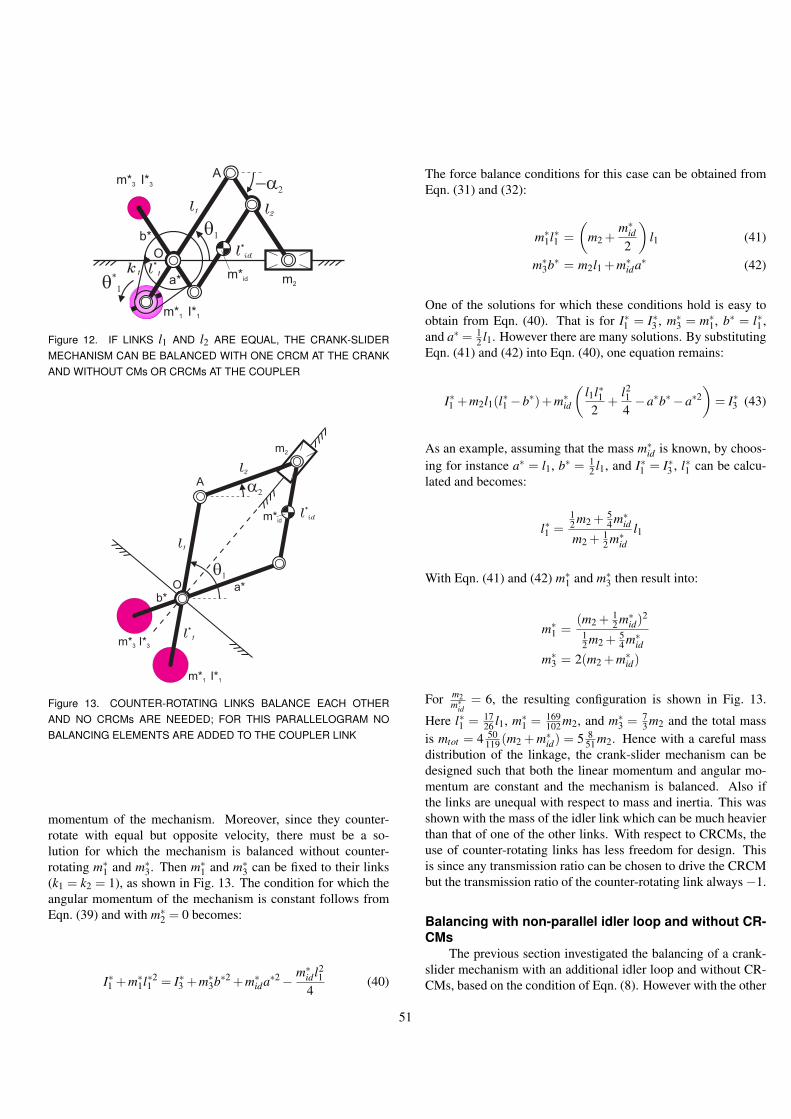
A
Ok
1
l1
m2
l*
1
m*1 I*1
-a2
l2
q1
q*
1
m*3 I*3
a*
b*
m*id
l*
id
Figure 12. IF LINKS l1 AND l2 ARE EQUAL, THE CRANK-SLIDERMECHANISM CAN BE BALANCED WITH ONE CRCM AT THE CRANKAND WITHOUT CMs OR CRCMs AT THE COUPLER
A
O
l*
1
m2
l1
l2
m*3 I*3
m*1 I*1
m*id
a*b*
l*
id
a2
q1
Figure 13. COUNTER-ROTATING LINKS BALANCE EACH OTHERAND NO CRCMs ARE NEEDED; FOR THIS PARALLELOGRAM NOBALANCING ELEMENTS ARE ADDED TO THE COUPLER LINK
momentum of the mechanism. Moreover, since they counter-rotate with equal but opposite velocity, there must be a so-lution for which the mechanism is balanced without counter-rotating m∗
1 and m∗3. Then m∗
1 and m∗3 can be fixed to their links
(k1 = k2 = 1), as shown in Fig. 13. The condition for which theangular momentum of the mechanism is constant follows fromEqn. (39) and with m∗
2 = 0 becomes:
I∗1 +m∗1l∗2
1 = I∗3 +m∗3b∗2 +m∗
ida∗2− m∗id l2
14
(40)
The force balance conditions for this case can be obtained fromEqn. (31) and (32):
m∗1l∗1 =
(m2 +
m∗id
2
)l1 (41)
m∗3b∗ = m2l1 +m∗
ida∗ (42)
One of the solutions for which these conditions hold is easy toobtain from Eqn. (40). That is for I∗1 = I∗3 , m∗
3 = m∗1, b∗ = l∗1 ,
and a∗ = 12 l1. However there are many solutions. By substituting
Eqn. (41) and (42) into Eqn. (40), one equation remains:
I∗1 +m2l1(l∗1 −b∗)+m∗id
(l1l∗12
+l214−a∗b∗−a∗2
)= I∗3 (43)
As an example, assuming that the mass m∗id is known, by choos-
ing for instance a∗ = l1, b∗ = 12 l1, and I∗1 = I∗3 , l∗1 can be calcu-
lated and becomes:
l∗1 =12 m2 + 5
4 m∗id
m2 + 12 m∗
idl1
With Eqn. (41) and (42) m∗1 and m∗
3 then result into:
m∗1 =
(m2 + 12 m∗
id)2
12 m2 + 5
4 m∗id
m∗3 = 2(m2 +m∗
id)
For m2m∗id
= 6, the resulting configuration is shown in Fig. 13.
Here l∗1 = 1726 l1, m∗
1 = 169102 m2, and m∗
3 = 73 m2 and the total mass
is mtot = 4 50119 (m2 + m∗
id) = 5 851 m2. Hence with a careful mass
distribution of the linkage, the crank-slider mechanism can bedesigned such that both the linear momentum and angular mo-mentum are constant and the mechanism is balanced. Also ifthe links are unequal with respect to mass and inertia. This wasshown with the mass of the idler link which can be much heavierthan that of one of the other links. With respect to CRCMs, theuse of counter-rotating links has less freedom for design. Thisis since any transmission ratio can be chosen to drive the CRCMbut the transmission ratio of the counter-rotating link always−1.
Balancing with non-parallel idler loop and without CR-CMs
The previous section investigated the balancing of a crank-slider mechanism with an additional idler loop and without CR-CMs, based on the condition of Eqn. (8). However with the other
51

O
l*
2
l*
3
l3
l1
l4
m*2 I*2
m*3 I*3
l2
l*
4
m*4 I*4
m*1 I*1
l*
1
xy
h1
h1
h2
h2
a
q
q
aA
B
m2
Figure 14. THE LINKS DO NOT NEED TO BE PARALLEL, THISMIRROR SYMMETRIC MECHANISM WITH SLIDER OFFSET IS BAL-ANCED WITHOUT CRCMs
condition for the moment balance of the configuration of Fig. 11,Eqn. (36), it must also be possible to obtain a balanced mecha-nisms without CRCMs. That would mean that the offset of theslider with respect to the origin is maintained and the length ofthe links l1 and l2 do not have to be equal.
Figure 14 shows a possible configuration for which the idlerloop, link 3 and link 4, is not anymore parallel to the initial link-age, link 1 and link 2. The links are connected to the base andslider at offsets h1 and h2 which do not have to be equal. Eachoffset however is symmetric with respect to the slider trajectory.Hereby the angular velocity of link 3 is equal but opposite to thatof link 1 and the angular velocity of link 4 is equal but oppositeto that of link 2 for the following conditions:
l1 = l3 l2 = l4 (44)
To obtain a balanced mechanism that is as symmetric as pos-sible, half of mass m2 can be modeled at the end of link 2 and link4. However it is also possible to model m2 at the end of one ofthese links. The calculations in this section are done with theformer option. Therefore there are two position vectors for m2.For the calculation of the conditions for which this crank-slidermechanisms is balanced, the positions of the masses can be writ-
ten in vector notation [x,y,z]T as:
r∗1 =
−l∗1 cosθ
h1− l∗1 sinθ0
r2,a =
l1 cosθ+ l2 cosαh1 + l1 sinθ+ l2 sinα
0
r2,b =
l3 cosθ+ l4 cosα−h1− l3 sinθ− l4 sinα
0
r∗2 =
l1 cosθ− l∗2 cosαh1 + l1 sinθ− l∗2 sinα
0
r∗3 =
−l∗3 cosθ−h1 + l∗3 sinθ
0
r∗4 =
l3 cosθ− l∗4 cosα−h1− l3 sinθ+ l∗4 sinα
0
With the derivatives of these position vectors the linear momen-tum of this mechanism can be written as:
pO = m∗1r∗1 +m2r2 +m∗
2r∗2 +m∗3r∗3 +m∗
4r∗4
=
(m∗1l∗1 − 1
2 m2(l1 + l3)−m∗2l1 +m∗
3l∗3 −m∗4l3)θ1 sinθ1+
(− 12 m2(l2 + l4)+m∗
2l∗2 +m∗4l∗4)α2 sinα2
(−m∗1l∗1 + 1
2 m2(l1− l3)+m∗2l1 +m∗
3l∗3 −m∗4l3)θ1 cosθ1+
( 12 m2(l2− l4)−m∗
2l∗2 +m∗4l∗4)α2 cosα2
0
(45)
A constant linear momentum for any motion is found for the fol-lowing conditions:
m∗1l∗1 = (
12
m2 +m∗2)l1 (46)
m∗3l∗3 = (
12
m2 +m∗4)l3 (47)
m∗2l∗2 =
12
m2l2 (48)
m∗4l∗4 =
12
m2l4 (49)
The angular momentum of this mechanism can be written as:
hO,z = (I∗1 − I∗3 )θ+(I∗2 − I∗4 )α+
r∗1×m∗1r∗1 + r2,a× m2
2r2,a + r2,b× m2
2r2,b +
r∗2×m∗2r∗2 + r∗3×m∗
3r∗3 + r∗4×m∗4r∗4
= (I∗1 − I∗3 )θ+(I∗2 − I∗4 )α+((
m2l22
−m∗2l∗2)l1− (
m2l42
−m∗4l∗4)l3
)(θ+ α)cos(θ−α)+
(m∗
1l∗21 +(
12
m2 +m∗2)l
21 −m∗
3l∗23 − (
12
m2 +m∗4)l
23
)θ+
52

O
l*
2
l*
3
l3
m2
l1
m*2 I*2
m*3 I*3
l2
l*
4
m*4 I*4
m*1 I*1
l*
1
xy
h1
h1
h2
a
q
q
aA
B
h2
l4
madd
Figure 15. ALSO THE MIRROR SYMMETRY IS NOT NECESSARY,AS LONG AS THE INERTIA OF TWO COUNTER-ROTATING LINKS ISEQUAL
(m∗
2l∗22 +
12
m2l22 −
12
m2l24 −m∗
4l∗24
)α+
(m∗3l∗3 −m∗
1l∗1 +(12
m2 +m∗2)l1− (
12
m2 +m∗4)l3)h1θsinθ+
(−m∗2l∗2 −
12
m2l4 +12
m2l2 +m∗4l∗4)h1αsinα (50)
Substituting the conditions of Eqn. (46-49), results into:
hO,z = (I∗1 − I∗3 )θ+(I∗2 − I∗4 )α+(m∗
1l∗1(l∗1 + l1)−m∗3l∗3(l∗3 + l3)) θ+
(m∗2l∗2(l∗2 + l2)−m∗
4l∗4(l∗4 + l4)) α (51)
and the angular momentum is constant if:
I∗1 − I∗3 +m∗1l∗1(l∗1 + l1)−m∗
3l∗3(l∗3 + l3) = 0 (52)I∗2 − I∗4 +m∗
2l∗2(l∗2 + l2)−m∗4l∗4(l∗4 + l4) = 0 (53)
This means that the inertia of link 1 with the total mass of link 2being concentrated at A, must be equal to the inertia of link 3 withthe total mass of link 4 being concentrated at B. Also the inertiaof link 2 must be equal to the inertia of link 4. One obvioussolution is for I∗1 = I∗3 , I∗2 = I∗4 , l∗1 = l∗3 , l∗2 = l∗4 , m∗
2 = m∗4 and
m∗1 = m∗
3, for which the crank-slider mechanism is line symmetricas shown in Fig. 14. However with this interpretation, the crank-slider mechanism can also be non-symmetric, for instance due tothe addition of a mass madd to link 4. This is shown in Fig. 15.
To maintain the force balance of link 4 about B, the force balancecondition of Eqn. (49) has to be adapted to:
m∗4l∗4 =
12(m2 +madd)l4 (54)
The inertia of link 2 is equal to the inertia of link 4 if:
m∗2l∗2
2 +12
m2l22 = m∗
4l∗24 +(
12
m2 +14
madd)l24 (55)
Substituting Eqn. (44) and (54) into this inertia equation resultsinto:
(m2 +madd)l∗4 +12
madd l2 = m2l∗2 (56)
Due to the additional mass at link 4, also the force balance con-dition of Eqn. (48) changes to:
m∗3l∗3 = (
12
m2 +m∗4 +madd)l3 (57)
and the inertia of link 1 and link 3 are equal if:
m∗1l∗2
1 +(12
m2 +m∗2)l
21 = m∗
3l∗23 +(
12
m2 +m∗4 +madd)l2
3 (58)
Eqn. (52) and (53) show that is also possible to scale oneside of the linkage as is done in Fig. 16. The slider is divided intwo and a pair of gears attached to link 1 and link 3 is used tosynchronize the motion of each part of the linkage. By scalingone part of the linkage, the symmetric motion of link 1 and 2with link 3 and 4 is maintained by:
l2l1
=l4l3
l1h1
=l3h∗1
l2h2
=l4h∗2
(59)
and the mass and inertia conditions determine the design of thelinks.
This section showed that an arbitrary crank-slider mecha-nism can be balanced both with and without the use of CRCMsby adding two synchronously counter-rotating links. Balancingwithout CRCMs can be done by a careful mass-redistribution ofthe links, while balancing with CRCMs gives more design free-dom due to the choice of the transmission ratio. The resultingbalanced crank-slider mechanisms balanced without CRCMs donot have to be symmetric. The configurations of crank-slidermechanisms that can be balanced if the slider trajectory has anoffset, are also suitable for curved slider trajectories.
53

O
l*
2
l*
3
l3
½m2
l1
l4
m*2 I*2
m*3 I*3
l2
l*
4
m*4 I*4m*1 I*1
l*
1
xy
h1
h*1
h*2
h2
a
q
q
a
madd
A
B
½m2
Figure 16. WITH THE PROPERTY OF EQUAL INERTIA OF TWOCOUNTER-ROTATING LINKS, EACH SIDE CAN BE SCALED W.R.T.THE OTHER SIDE; SYNCHRONOUS MOTION IS SATISFIED BY US-ING GEARS
NO BALANCING ELEMENTS AT THE COUPLERThe configuration of Fig. 9 is interesting since only one
CRCM and no CMs are necessary for the force and moment bal-ance of the mechanism. However in practice, the lengths of link1 and link 2 of the crank-slider mechanisms will often need to beunequal and an offset will be needed. The reason why these twolinks have to be equal was the condition of Eqn. (8) for which noCM needed to be attached to the coupler to balance the mecha-nism.
The configurations of the balanced crank-slider mechanismsin the previous section are interesting since no CRCMs are nec-essary. Since the links counter-rotate with respect to each other,by a specific mass distribution the links balance their opponents.
This section tries to combine both advantages. A crank-slider configuration is investigated which is balanced by only oneCRCM and for which there are no CMs at the coupler. It is pro-posed to add three synchronously with the coupler rotating linksto the initial crank-slider mechanism as shown in Fig. 17. Thereason to add these three links in this way is that, as shown inthe previous section, the angular momentum of two links that areequal and counter-rotate synchronously is zero.
In Fig. 17, link 2 and link 4 are parallel to link 3 and link5, respectively. The angles and angular velocity of link 2 andlink 3 are equal but opposite to that of link 4 and link 5. Link4 is connected at link 1 at a distance a∗ from the origin O andhas a slider with mass m∗
4 that slides at an offset h4. Link 5 isconnected to link 1 at a distance l∗1 and has a slider with mass m∗
5that slides at an offset h5. Link 3 in this case is connected to link1 at a distance b∗ from O.
The conditions for which the symmetric motion of the links
m*4
O
l1
m2
l*
4
-a2
l2
q1
xyh2
l*
1
m*3 I*3
A
q2
m*5l
*
3
l*
5
h3
-a2
a*
b*
h4
h5k
1
-a2
-a2B
m 2l,
m*l,4
m*l,3
m*l,1
m*l,5
m 2l,
k2
C
Figure 17. CRANK-SLIDER MECHANISM WITH THREE ADDITIONALSYNCHRONOUSLY ROTATING LINKS ATTACHED TO THE CRANKAND ONE CRCM (UNBALANCED)
is maintained follow from the similarity of triangles:
l2l1
=l∗3b∗
=l∗4a∗
=l∗5l∗1
h2
l1=
h3
b∗=
h4
a∗=
h5
l∗1(60)
The moment of the mechanism is balanced by CRCM m∗3 with
inertia I∗3 , which is driven the same way as the configuration inFig. 8. The masses of the links are assumed to be at each link’sgeometric center.
To obtain the conditions for which this mechanism is forcebalanced and moment balanced, the slider masses can be treatedseparately from the link masses. First the balance conditions forthe slider masses will be calculated, followed by the calculationsfor the link masses.
The positions of the slider masses can be written in vectornotation [x,y,z]T as:
r2 =
l1 cosθ1 + l2 cosα2h20
r∗3 =
−b∗ cosθ1− l∗3 cosα2
−h30
r∗4 =
a∗ cosθ1− l∗4 cosα2h40
r∗5 =
−l∗1 cosθ1 + l∗5 cosα2
−h50
With the derivatives of the position vectors, the linear momentumcan be written as:
pO = m2r2 +m∗2r∗2 +m∗
3r∗3 +m∗4r∗4
54

=
(−m2l1 +m∗3b∗−m∗
4a∗+m∗5l∗1)θ1 sinθ1+
(−m2l2 +m∗3l∗3 +m∗
4l∗4 −m∗5l∗5)α2 sinα2
00
(61)
The linear momentum is constant if:
m∗3b∗+m∗
5l∗1 = m2l1 +m∗4a∗ (62)
m∗3l∗3 +m∗
4l∗4 = m2l2 +m∗5l∗5 (63)
The angular momentum can be written as:
hO,z = I∗3 α∗2 + r2×m2r2 + r∗2×m∗2r∗2 +
r∗3×m∗3r∗3 + r∗4×m∗
4r∗4= I∗3 α∗2 +(m2l1h2 +m∗
3b∗h3 +m∗4a∗h4 +m∗
5l∗1h5)θ1 sinθ1 +(m2l2h2 +m∗
3l∗3h3−m∗4l∗4h4−m∗
5l∗5h5)α2 sinα2 (64)
The crank-slider mechanism can only be balanced by use of aCRCM if h2 = h3 = h4 = h5 = 0 for which the angular momen-tum of the slider masses is zero. In that case the slider massesmove along a line through O and do not produce a shaking mo-ment. Hence the CRCM does not have to rotate. Besides fromEqn. (62) and (63) is found that CMs m∗
4 and m∗5 can be zero and
therefore vanish.The positions of the link masses can be written in vector
notation [x,y,z]T as:
rl,1 =
l12 cosθ1l12 sinθ1
0
r∗l,1 =
− l∗1
2 cosθ1
− l∗12 sinθ1
0
rl,2 =
l1 cosθ1 + l22 cosα2
l1 sinθ1 + l22 sinα2
0
r∗l,3 =
−b∗ cosθ1− l∗3
2 cosα2
−b∗ sinθ1− l∗32 sinα2
0
r∗l,4 =
a∗ cosθ1− l∗42 cosα2
a∗ sinθ1 + l∗42 sinα2
0
r∗l,5 =
−l∗1 cosθ1 + l∗5
2 cosα2
−l∗1 sinθ1− l∗52 sinα2
0
With the derivatives of the position vectors, the linear momentumof the link masses can be written as:
pO = ml,1rl,1 +m∗l,1r∗l,1 +ml,2rl,2 +m∗
l,3r∗l,3 +m∗l,4r∗l,4 +m∗
l,5r∗l,5
=
(− 12 ml,1l1 + 1
2 m∗l,1l∗1 −ml,2l1 +m∗
l,3b∗−m∗l,4a∗+
m∗l,5l∗1)θ1 sinθ1 +(− 1
2 ml,2l2 + 12 m∗
l,3l∗3+12 m∗
l,4l∗4 − 12 m∗
l,5l∗5)α2 sinα2
( 12 ml,1l1− 1
2 m∗l,1l∗1 +ml,2l1−m∗
l,3b∗+m∗l,4a∗−
m∗l,5l∗1)θ1 cosθ1 +( 1
2 ml,2l2− 12 m∗
l,3l∗3+12 m∗
l,4l∗4 − 12 m∗
l,5l∗5)α2 cosα2
0
(65)
The linear momentum is constant for any motion if:
12
m∗l,1l∗1 +m∗
l,3b∗+m∗l,5l∗1 =
12
ml,1l1 +ml,2l1 +m∗l,4a∗ (66)
ml,2l2 = m∗l,3l∗3 (67)
m∗l,4l∗4 = m∗
l,5l∗5 (68)
The angular momentum of the link masses is written as:
hO,z = I∗3 α∗2 + rl,1×ml,1rl,1 + r∗l,1×m∗l,1r∗l,1 + rl,2×ml,2rl,2 +
r∗l,3×m∗l,3r∗l,3 + r∗l,4×m∗
l,4r∗l,4 + r∗l,5×m∗l,5r∗l,5
= I∗3 α∗2 +(14
ml,1l21 +
14
m∗l,1l∗2
1 +ml,2l21 +m∗
l,3b∗2 +
m∗l,4a∗2 +m∗
l,5l∗21 )θ1 +
14(ml,2l2
2 +m∗l,3l∗2
3 −m∗l,4l∗2
4 −m∗l,5l∗2
5 )α2 +
12(ml,2l1l2 +m∗
l,3b∗l∗3)(θ1 + α2)cos(θ1−α2)−12(m∗
l,4a∗l∗4 +ml,5∗ l∗1 l∗5)(θ1− α2)cos(θ1 +α2) (69)
The last two terms can be reduced to (−m∗l,4a∗2−m∗
l,5l∗21 )θ1 if:
ml,2l1l2 = m∗l,4a∗l∗4 (70)
m∗l,3b∗l∗3 = m∗
l,5l∗1 l∗5 (71)
or:
ml,2l1l2 = m∗l,5l∗1 l∗5 (72)
m∗l,3b∗l∗3 = m∗
l,4a∗l∗4 (73)
and by substituting the equations for the angle α2 (Eqn. (9-10)).The angular momentum can then be rewritten as:
hO,z = I∗3 α∗2 +(14
ml,1l21 +
14
m∗l,1l∗2
1 +ml,2l21 +m∗
l,3b∗2)θ1 +
14(ml,2l2
2 +m∗l,3l∗2
3 −m∗l,4l∗2
4 −m∗l,5l∗2
5 )α2 (74)
55

m*4
O
l1=a*
m2
l*
4
-a2
l2
q1
xy
l*
1=b*
m*3 I*3
A
m*5
l*
3l
*
5
k1
-a2
-a2
m 2l,m* 4l,
m*l,5m*
l,3
ml,1
m*l,1
B
-a2
Figure 18. BALANCED CONFIGURATION IN WHICH l2 = l∗4 and l∗3 =l∗5 ; MASSES m∗
4 AND m∗5 CAN BE ZERO AND EACH SIDE CAN BE
SCALED; THE COUNTER ROTATION OF THE CRCM IS ONLY NEEDEDTO BALANCE THE MOMENT OF THE CRANK
m*4O
l1
m2
l*
4
-a2
l2
q1
xy
l*
1
m*3 I*3
A
m*5
l*
3
l*
5k1
-a2
-a2
-a2
m 2l,
m* 4l,
m*l,5
m*l,3
ml,1
m*l,1
B
a*
b*
Figure 19. BALANCED CONFIGURATION IN WHICH l2 = l∗5 and l∗3 =l∗4 ; MASSES m∗
4 AND m∗5 CAN BE ZERO AND EACH SIDE CAN BE
SCALED; MORE SOLUTIONS ARE POSSIBLE
With the kinematic relation of α∗2:
α∗2 = k1(1− k2)θ1 + k2α2 (75)
The mechanism is balanced if the CRCM inertia I∗3 holds:
I∗3 =14 ml,1l2
1 + 14 m∗
l,1l∗21 +ml,2l2
1 +m∗l,3b∗2
k1(1− k2)(76)
I∗3 =14 (ml,2l2
2 +m∗l,3l∗2
3 −m∗l,4l∗2
4 −m∗l,5l∗2
5 )
k2(77)
In case l2 = l∗4 and l∗3 = l∗5 or l2 = l∗5 and l∗3 = l∗4 , the secondequation for I∗3 is zero and the counter-rotation depends only onθ1. From Eqn. (60) holds that for the first solution a∗ = l1 and
b∗ = l∗1 , which is the configuration of Fig. 18. For the secondsolution l1 = l∗1 and a∗ = b∗ and this configuration is shown inFig. 19. The belt connection along link 3 then is parallel.
This section investigated a crank-slider mechanism forwhich no balancing elements needed to be added to the cou-pler. This was done by adding 3 links to the crank that movesynchronously with the coupler link. With respect to the config-uration of Fig. 5, the two CMs are zero and only one CRCM isused for the force and moment balance of the complete mecha-nism. The advantage with respect to the configuration of Fig. 9 isthat the length of the crank and coupler do not have to be equal.
ConclusionThe investigation of CRCM-balanced crank-slider mecha-
nisms in this chapter resulted into various interesting configura-tions. By addition of one, two or three links which move syn-chronously with the coupler link, the balancing elements wereeliminated from the coupler and placed at the crank or at thebase. Configurations were found without balancing elements atthe coupler and only one CRCM for the moment balance of thecomplete crank-slider mechanism. However these configurationsdo not allow an offset of the slider with the origin.
If an offset is necessary, balanced crank-slider mechanismscan be obtained by a careful mass-redistribution of the additionallinks. By having these links counter-rotate with respect to thecrank-slider links, balanced configurations were found that donot need CRCMs. However a CM at the coupler of the crank-slider mechanism is still necessary to allow an offset. Eliminat-ing this CM and maintaining the offset might be the first targetto pursue.
REFERENCES[1] Klein Breteler, A. J., 2004. Mechanisms. TU Delft.[2] VDI2149, 1999. “Blatt 1: Getriebedynamik-starrkorper
mechanismen (dynamics of mechanisms-rigid body mech-anisms)”. Verein Deutscher Ingenieure - Richtlinien.
[3] Lowen, G. G., and Berkof, R. S., 1968. “Survey of investi-gations into the balancing of linkages”. Journal of Mecha-nisms, 3, pp. 221–231.
[4] Van der Wijk, V., and Herder, J. L., 2008. “Double pendu-lum balanced by counter-rotary counter-masses as useful el-ement for synthesis of dynamically balanced mechanisms”.Proceedings of DETC 2008, ASME (accepted),(DETC2008-49402).
[5] Arakelian, V. G., and Smith, M. R., 2005. “Shaking forceand shaking moment balancing of mechanisms: A historicalreview with new examples”. Journal of Mechanical Design,127, pp. 334–339.
[6] Arakelian, V. H., and Smith, M. R., 2005. “Erratum: Shak-ing force and shaking moment balancing of mechanisms: A
56

historical review with new examples”. Journal of Mechani-cal Design, 127, p. 1035.
[7] Crone, H. A., 2002. Ontwerpen van Machines en Mechanis-men. TU Delft.
[8] Husing, M., 2000. Maschinendynamik II - Lecture Notes.IGM RWTH Aachen.
57

CHAPTER 6-
DYNAMIC BALANCING OF MECHANISMS BYUSING AN ACTIVELY DRIVEN
COUNTER-ROTARY COUNTER-MASS FOR LOWMASS AND LOW INERTIA
V. van der Wijk, J.L. HerderFaculty of Mechanical Engineering, Delft University of Technology
Submitted to Second International Workshop onFundamental Issues and Future Research Directions
for Parallel Mechanisms and Manipulators,Montpellier, France, 2008.
58

DYNAMIC BALANCING OF MECHANISMS BY USING AN ACTIVELY DRIVENCOUNTER-ROTARY COUNTER-MASS FOR LOW MASS AND LOW INERTIA
V. van der Wijk, J.L. HerderFaculty of Mechanical Engineering, Delft University of Technology
ABSTRACTDynamic balancing of mechanisms still goes together with a considerable increase of mass and inertia. The goal of this
article is to actively balance various useful 1-, 2-, and 3-degree-of-freedom planar and spatial, serial and parallel mechanismsand to show that active balancing is a good alternative for low mass and low inertia dynamic balancing. It is proposed to forcebalance mechanisms with the minimum number of counter-masses and use the inertia of these counter-masses to balance themoment by actively controlling them with an additional actuator. The counter-masses then are driven such that they counter-rotate with respect to the mechanism and the dynamic balance is obtained. Herewith the advantages for low mass and low inertiaof the counter-rotary counter-mass (CRCM-) principle and the principle of duplicate mechanisms (DM) where a mechanismis balanced altogether (instead of link by link), are combined. A double pendulum is actively balanced, compared with otherbalancing principles, and used for the synthesis of various actively balanced manipulators.
It was found that dynamic balancing by active control of the CRCM (ACRCM) results into a better total mass-inertia relationthen balancing with nonactive CRCMs or using separate counter-rotations for the moment balance. The DM-principle still isbetter, however the size of the ACRCM-balanced mechanism is considerably smaller. For a low mass and low inertia addition,the ACRCM should have a large inertia and a low mass. Active control of the ACRCM has the advantage of being able tocompensate for disturbances that affect the moment balance, such as drift, belt elasticity or external forces. Disadvantages arethe addition of a controlled actuator and difficulty to handle high accelerations as for example due to impact. It is shown that aplanar 3-RRR parallel manipulator and a spatial 3-RRR parallel manipulator can be dynamically balanced with respectively oneand two ACRCMs. It is also shown that a 3-DOF planar 1-RRR serial manipulator can be completely dynamically balanced bya single ACRCM.
1 INTRODUCTIONDynamic balancing of mechanisms with a low addition of
mass and a low addition of inertia is an important target. Moreinertia means that more power is needed to drive the mecha-nism while more mass means more power to lift and controlthe object in free space and an increase of material costs [1].To dynamically balance a mechanism, often counter-masses areadded to force balance mechanism links and separate counter-rotations (SCR) [2, 3], or counter-rotary counter-masses (CR-CMs) [4,5] are used to balance the moment of the links. With theSCR-principle, a mechanism link is force balanced first, then byadding a separate counter-rotating inertia element, the momentof the link is balanced.
With the CRCM-principle the moment of a mechanism linkis balanced by counter-rotation the counter-mass that is used forthe force balance of the link. The CRCM-principle has provento be more advantageous for low mass and low inertia dynamicbalancing than the SCR-principle [1, 5, 6]. It is also possible tobalance the complete mechanism altogether instead of link by
link, by duplicating it two times [7]. This duplicate mechanisms(DM-)principle proved to be the best for low mass and low iner-tia dynamic balancing [6], but is generally a complex and spaceconsuming balancing principle.
With the target to find ways to balance mechanisms alto-gether when few space is available, Hilpert’s solution to forcebalance 4R-four bar mechanisms by adding a pantograph with asingle counter-mass [8], is useful. It was shown that the COMof a 4R-four bar mechanism can be materialized with additionalparallel links. By connecting one end of the pantograph to thecenter of mass (COM) and connecting the pivot of the panto-graph to the base, the overall COM could be made stationary.This implies that any mechanism of which the COM can be ma-terialized can be force balanced with a pantograph and a singlecounter-mass.
Since in planar mechanisms the shaking moment existssolely in one plane, it is possible to balance the moment of anyplanar mechanism by only one counter-rotating element. To keepthe addition of mass and inertia low, it seems obvious to use the
59

counter-mass also for the moment balance by having it counter-rotate with respect to the mechanism.
Contrary to the configurations in [1, 5, 6], balancing amore than 1-degree of freedom (DOF) mechanism with a sin-gle counter-mass leads to a mass distribution (reduced inertia ofthe mechanism [9]) that depends on the position of the mecha-nism. Then it is not possible to balance the mechanism by drivingthe CRCM with, for instance, a pair of gears since the counter-rotation of the CRCM then solely depends on the velocity of themechanism. Therefore it is proposed to drive the counter-rotationactively. Then, next to the actuators that are used to drive themechanism, an extra actuator is included that solely actuates thecounter-rotary counter-mass (ACRCM).
The goal of this article is to actively balance various useful1-, 2-, and 3-degree-of-freedom planar and spatial, serial and par-allel mechanisms and to compare the result with known passive(i.e. non-active) balancers.
The approach is to balance a double pendulum with anACRCM first and then use this balanced double pendulum for thesynthesis of new ACRCM-balanced mechanisms. With the mo-mentum equations the conditions for the dynamic balance andthe equations of the total mass and the reduced inertia of themechanism are obtained. A numerical example is carried out andthe results are compared to the passive (non-active) balancingprinciples. At the end it is shown that also a planar 3-DOF serialmechanism can be balanced actively with just a single ACRCM.
2 BALANCED DOUBLE PENDULUM WITH ONEACRCMIn [1] a double pendulum (also called dyad [10]) was found
to be an important building element in the synthesis of mecha-nisms. In addition it was found to be a suitable mechanism for acomparative study of balancing principles regarding the additionof mass and the addition of inertia.
Figure 1 shows a dynamically balanced double pendulumwith a single ACRCM. The initial double pendulum before bal-ancing consists of link 1 with length l1 and link 2 with length l2.At the endpoint of link 2 there is a lumped mass m with inertia I.This lumped mass can represent a payload, the mass and inertiaof link 2, or both.
The mechanism has two degrees of freedom which are de-scribed by θ1 and θ2. These are the relative angles between twoconnecting links. The absolute angle of link 2 with the referenceframe is α2. The x-axis of the reference frame is chosen to bealong the base link for which the absolute angle of link 1 is equalto θ1.
For the force balance of the double pendulum, two parallellinks are added such that the double pendulum is changed into apantograph mechanism. The ACRCM with mass m∗ and inertiaI∗ is placed at link BC at a distance u from B such that the COMof the complete mechanism becomes stationary at the origin O.
A
O
l1
l*
1
q2
q1
B
E
l*
2
e3
e1
MO
m I
m* I*
C
D
xy
a2
l2
g1
a1
b1
u
e2
Figure 1. COMPLETELY BALANCED DOUBLE PENDULUM BY USINGA SINGLE ACTIVELY DRIVEN COUNTER-ROTARY COUNTER-MASS(ACRCM); AN ADDITIONAL ACTUATOR DRIVES THE GEAR AT O BYWHICH THE ACRCM COUNTER-ROTATES WITH RESPECT TO THEMECHANISM
For the moment balance, the ACRCM is driven by a belttransmission along the gears at B and O. The gear at O is notfixed to the base, but is driven by an actuator that applies a torqueMO to this gear.
For the calculations, the combined mass of link 1 and its par-allel link CD me1 is at e1, the location of the lumped mass is e2and the position of the ACRCM is e3. For the ease of calcula-tion, the mass of link BC is neglected. However including it ispossible. The positions of e1, e2 and e3 can be written in vectornotation [x,y,z]T as:
re1 =
a1 cosθ1−b1 cosα2a1 sinθ1−b1 sinα2
0
re2 =
l1 cosθ1 + l∗2 cosα2l1 sinθ1 + l∗2 sinα2
0
re3 =
−l∗1 cosθ1−ucosα2−l∗1 sinθ1−usinα2
0
in which α2 is related to θ1 and θ2 by α2 = θ1 + θ2−π. Fromthe conservation of momentum method [1, 5] it is known thata mechanism is force balanced if the linear momentum of themechanism is constant and that a mechanism is moment balancedif the angular momentum of the mechanism is constant. With thederivatives of the position vectors, the linear momentum of themechanism can be written as:
pO = me1 re1 +mre2 +m∗re3
60
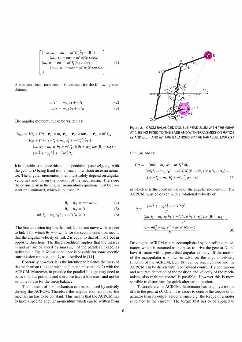
=
(−me1 a1−ml1 +m∗l∗1)θ1 sinθ1+(me,1b1−ml2 +m∗u)α2 sinα2
(me1 a1 +ml1−m∗l∗1)θ1 cosθ1+(−me,1b1 +ml2−m∗u)α2 cosα2
0
(1)
A constant linear momentum is obtained for the following con-ditions:
m∗l∗1 = me1a1 +ml1 (2)ml2 = me,1b1 +m∗u (3)
The angular momentum can be written as:
hO,z = Iα2 + I∗γ+ re1 ×me1 re1 + re2 ×mre2 + re3 ×m∗re3
= Iα2 + I∗γ+(ml21 +me1a2
1 +m∗l∗21 )θ1 +
(ml1l2−me1a1b1 +m∗l∗1u)(θ1 + α2)cos(θ1−α2)+
(ml22 +me1 b2
1 +m∗u2)α2
It is possible to balance this double pendulum passively, e.g. withthe gear at O being fixed to the base and without an extra actua-tor. The angular momentum then must solely depend on angularvelocities and not on the position of the mechanism. Thereforethe cosine term in the angular momentum equations must be con-stant or eliminated, which is the case if:
θ1−α2 = constant (4)θ1 + α2 = 0 (5)
ml1l2−me1 a1b1 +m∗l∗1u = 0 (6)
The first condition implies that link 2 does not move with respectto link 1 for which θ2 = 0, while for the second condition meansthat the angular velocity of link 2 is equal to that of link 1 but inopposite direction. The third condition implies that the massesm and m∗ are balanced by mass me1 of the parallel linkage, asindicated in Fig. 2. Moment balance is possible for some specifictransmission ratios k1 and k2 as described in [11].
Contrarily however, it is the intention to balance the mass ofthe mechanism (linkage with the lumped mass at link 2) with theACRCM. Moreover, in practice the parallel linkage may need tobe as small as possible and therefore have a low mass and not besuitable to use for the force balance.
The moment of the mechanism can be balanced by activelydriving the ACRCM. Therefore the angular momentum of themechanism has to be constant. This means that the ACRCM hasto have a specific angular momentum which can be written from
A
l1
q2
E
e3
e1
m I
m* I*
C
D
xy
a2
l2
g1
-uk
2
k1
O
l*
1
q1
B
l*
2
e2
a1
b1
Figure 2. CRCM BALANCED DOUBLE PENDULUM WITH THE GEARAT O BEING FIXED TO THE BASE AND WITH TRANSMISSION RATIOSk1 AND k2; m AND m∗ ARE BALANCED BY THE PARALLEL LINK CD
Eqn. (4) and is:
I∗γ = −(ml21 +me1 a2
1 +m∗l∗21 )θ1−
(ml1l2−me1a1b1 +m∗l∗1u)(θ1 + α2)cos(θ1−α2)−(I +ml2
2 +me1 b21 +m∗u2)α2 +C (7)
in which C is the constant value of the angular momentum. TheACRCM must be driven with a rotational velocity of:
γ = − (ml21 +me1a2
1 +m∗l∗21 )θ1
I∗−
(ml1l2−me1 a1b1 +m∗l∗1u)(θ1 + α2)cos(θ1−α2)I∗
−(I +ml2
2 +me1b21 +m∗u2)α2−CI∗
(8)
Driving the ACRCM can be accomplished by controlling the ac-tuator, which is mounted to the base, to drive the gear at O andhave it rotate with a prescribed angular velocity. If the motionof the manipulator is known in advance, the angular velocityfunction of the ACRCM, Eqn. (8), can be precalculated and theACRCM can be driven with feedforward control. By continuousand accurate detection of the position and velocity of the mech-anism, also realtime control is possible. However this is moresensible to distortions for quick alternating motion.
To accelerate the ACRCM, the actuator has to apply a torqueMO to the gear at O. Often it is easier to control the torque of anactuator than its output velocity, since e.g. the torque of a motoris related to the current. The torque that has to be applied to
61

A
O
l1
l*
1
q2
q1
B
El
2
MO
m I
m* I*C
D
xy
k2
k1
a2
g1
l*
2
dO
dB,1
dB,2
d*
m
Figure 3. FOR ACTIVE BALANCING WITH TRANSMISSION RATIOSTHE OUTPUT VELOCITY OF THE ACTUATOR IS REDUCED
the gear at O can be calculated from the velocity function of theCRCM, Eqn. (8), as:
MO = I∗γ= −(ml2
1 +me1a21 +m∗l∗2
1 )θ1−(ml1l2−me1 a1b1 +m∗l∗1u)(θ1 + α2)cos(θ1−α2)+
(ml1l2−me1 a1b1 +m∗l∗1u)(θ21− α2
2)sin(θ1−α2)−(I +ml2
2 +me1b21 +m∗u2)α2 (9)
In fact, this torque is equal but opposite to the shaking momentthat the force balanced mechanism exerts to the base, which gen-erally can be obtained from:
Msh =ddt
hO,z (10)
For this case, the shaking moment is zero with MO of Eqn. (9)and the mechanisms is moment balanced.
2.1 TransmissionBy using an ACRCM, the transmission of the motion from
the gear at O to the ACRCM can be simple. For instance by par-allel belt drives for which the dimensions of the gears are equalas was shown in Fig. 1. However it is also possible to use trans-missions with different gears as shown in Fig. 3. The angularvelocity of the ACRCM then is influenced by the motion of thelinkage and depends on the gear ratios. The angular velocity ofthe ACRCM dependent on the motion of the mechanism can be
calculated by having the gear at O be fixed for rotation and be-comes:
γ = (1− dO
dB,1)
dB,2
d∗mθ1 +(1− dB,2
dm∗)θ2
= k1(1− k2)θ1 + k2θ2 (11)
with dO, dB,1, dB,2 and dm∗ being the diameter of the gear at O,the small gear at B, the large gear at B, and the gear at ACRCMm∗ respectively. k1 and k2 are the transmission ratios of the belttransmission of each link. For a parallel transmission, dO = dB,1and dB,2 = dm∗ and Eqn. (11) becomes zero. The motion of theACRCM then is not influenced by the motion of the linkage.
For gear diameters that differ and if the ACRCM is drivenby controlling the angular velocity of the actuator, the angular ve-locity of the actuator is different from the angular velocity of theACRCM. The angular velocity of the actuator can be calculatedby adding Eqn. (11) to the right term of the velocity function ofEqn. (8). This equation can be rewritten by which the angularvelocity of the actuator becomes:
γact ={−ml2
1 +me1 a21 +m∗l∗2
1I∗
− k1(1− k2)}
θ1−
(ml1l2−me1 a1b1 +m∗l∗1u)(θ1 + α2)cos(θ1−α2)I∗
+{− I +ml2
2 +me1 b21 +m∗u2
I∗
}α2− k2θ2 +
CI∗
(12)
For counter-rotations, the transmission ratios k1 and k2 are nega-tive and the output velocity of the actuator is reduced. Howeverthe moment that the actuator has to apply to the gear at O doesnot change. This is since the shaking moment depends solely onthe mechanism by Eqn. (10) and is not influenced by the designof the transmissions.
The actuator itself however can influence the dynamic bal-ance of the mechanism. If the actuator is a motor, then for analternating velocity the angular momentum of the rotor is notconstant. Hence the motor exerts a shaking moment to the base.
If a motor is driving the gear at O directly, e.g the gear at Ois attached to the shaft of the motor, the rotor rotates in the samedirection as the ACRCM. This means that the momentum of theACRCM can be smaller, which can be done by decreasing its in-ertia or decreasing its angular velocity. If the motor is driving theACRCM such that it counter-rotates with respect to the ACRCM,then the ACRCM must compensate and must have an increasedangular momentum.
2.2 Reduced Inertia and Total MassThe inertia of the mechanism is defined as the reduced iner-
tia Ired [9]. This is the inertia moment of all elements reduced to
62
the input angles of the mechanism. Since the reduced inertia isan essential characteristic of a mechanism [9], it can be used tocalculate the increase of inertia by balancing and by comparingdifferent balancing principles.
The inertia of the double pendulum can be reduced to thetwo input angles θ1 and θ2 and can be calculated by writing thekinetic energy equation of the manipulator for each input angle:
TO =12
Iredθ1
θ21 (13)
TA =12
Iredθ2
θ22 (14)
in which Iredθ1
and Iredθ2
are the reduced inertia moments about Oand A respectively. To calculate the reduced inertia about O, thekinetic energy of the complete balanced manipulator can be writ-ten as:
T =12
Iα22 +
12
I∗γ2 +12
me1 [re1 ]T [re1 ]+
12
m[re2 ]T [re2 ]+
12
m∗[re4 ]T [re4 ] (15)
The squared angular velocity of the ACRCM γ2 can be writtenfrom Eqn. (8) as:
γ2 ={
U θ1 +V θ2 +W (2θ1 + θ2)cosθ2 +C−I∗
}2
(16)
={
X−I∗
}2
with:
U = I +m(l21 + l2
2)+me1(a21 +b2
1)+m∗(l∗21 +u2)
V = I +ml22 +me1 b2
1 +m∗u2
W = −ml1l2 +me1a1b1−m∗l∗1u
By substituting Eqn. (16) into (15), the kinetic energy can berewritten as:
T =12
U θ21 +
X2
2I∗+
12
V (θ22 +2θ1θ2)+W (θ2
1 + θ1θ2)cosθ2
(17)
Assuming the constant angular momentum to be zero (C = 0),the kinetic energy TO is obtained by substituting θ2 = 0 into
Eqn. (17) and becomes:
TO =12
{U +2W cosθ2 +
(U +2W cosθ2)2
I∗
}θ2
1 (18)
The reduced inertia of the mechanism about O then is:
Iredθ1
= U +2W cosθ2 +(U +2W cosθ2)2
I∗(19)
For the reduced inertia about A, the kinetic energy of link 2 mustbe calculated with θ1 = 0. This equation is written as:
TA =12
{V +
V 2
I∗
}θ2
2 (20)
and the reduced inertia of the mechanism about A becomes:
Iredθ2
= V +V 2
I∗(21)
Generally for the (A)CRCM-principle, the equations for the re-duced inertia can be written in the form:
Iredθ = Ilink + k2I∗
in which Ilink is the inertia of the force balanced linkage about itsjoint, I∗ the inertia of the (A)CRCM and k the transmission ratio.Comparing this equation to Eqn. (19) and (21), the transmissionratios of the ACRCM can be derived and are:
k1 =U +2W cosθ2
I∗(22)
k2 =VI∗
(23)
The total mass of the ACRCM-balanced double pendulum is cal-culated with:
mtot = m+m∗+me1 (24)
2.3 Numerical Example and ComparisonWith a numerical example, the ACRCM-balanced double
pendulum is compared to the SCR-, CRCM-, and DM-principle.The results for these balancing principles were obtained from [1].For a fair comparison, the same parameter values were chosen
63

Table 1. PARAMETER VALUES
m = 0.3 [kg] l1 = 0.25 [m] t = 0.01 [m]
me1 = 0 [kg] l2 = 0.25 [m] ρ = 7800[kgm−3]
I = 184 [kgmm2]
Table 2. RESULTS OF A ACRCM-BALANCED DOUBLE PENDULUM
Ired
[kgm ]2
m* [kg]
0.9
2.79 1.86e 0.52-4< <I
q1
red
Iq2
red=0.41
mtot [kg] k [-]
3.83
1.2
3.09
4.13 1.85e 0.30-4< <I
q1
red
I =0.05red
q2
2.04e 6.17-4< <I
q1
red
I =0.03red
q2
0.01 5.24< <k1
k2=15.2
0.01 2.71< <k1
k =1.32
0.11 60.6< <k1
k =0.72
0.027
0.020
l *=1 u [m]
0.083
and are shown in Table 1. Also the mass me1 of the parallel link-age was chosen to be zero and the mass m and ACRCM m∗ weremodeled as discs with thickness t and density ρ. The mass andthe inertia of the ACRCM then are related as:
I∗ =m∗2
2ρπt(25)
Table 2 shows the results for some specific choices of mass m∗.For comparison, Table 3 shows the results for the three balancingprinciples. The choice for m∗ = 0.9kg results into a total massof mtot = 1.2kg, which is equal to the total mass of the DM-principle, the lowest total mass of all principles. However, themaximum inertia Ired
θ1in this case is more than 20 times larger
than that of the DM principle. Inertia Iredθ2
is lower than that ofthe DM-principle and is equal to Ired
θ2of the (passive) CRCM-
principle for k1 = k2 =−1, the lowest of all.For m∗ = 2.79kg, the total mass of the ACRCM-principle is
equal to that of the CRCM-principle for k1 = k2 = −16. In thiscase the maximum inertia for Ired
θ1is more than five times smaller
than that of the CRCM-principle while inertia Iredθ2
is about tentimes smaller.
The DM principle has the smallest maximum Iredθ1
of all thethree passive principles. For an equal maximum value for Ired
θ1
of 0.30kgm2, the total mass for the active ACRCM-principle be-comes mtot = 4.13kg. This is about three and a half times morethan the DM principle.
From the force balance conditions of Eqn. (2) and (3) andwith m∗ being known, the dimensions of l∗1 and u can be calcu-lated. These values are also shown in Table 2 and are relatively
Table 3. RESULTS OF PASSIVE BALANCING PRINCIPLES OB-TAINED FROM [1]
DuplicateMechanisms
SeparateCR
CRCM
Total Mass [kg]
TotalInertia[kgm ]
2
1.2038.7816.01
Ired
q1
Ired
q2
1.3620.640
0.0830.041 0.076
k1=k =-12
7.35e 0.30-4< <I
red
q1
Total Mass [kg]
TotalInertia[kgm ]
2
14.336.89
Ired
q1
Ired
q2
1.2750.992
0.1400.112
k1=k =-42
Total Mass [kg]
TotalInertia[kgm ]
2
9.364.68
Ired
q1
Ired
q2
1.6991.484
0.2390.213
k1=k =-82
Total Mass [kg]
TotalInertia[kgm ]
2
6.133.09
Ired
q1
Ired
q2
2.5312.650
0.4610.488
k1=k =-162
A
O
l1
l*
1
q2
q1
B
E
l*
2 m I
m* I*
C
D
xy
a2
l2
g1
Figure 4. ACRCM BALANCED DOUBLE PENDULUM WITH m∗ =3.83kg, DRAWN THE SCALE
small. This means that with ACRCMs the mechanism remainscompact. For mtot = 4.13kg, an ACRCM-balanced double pen-dulum is drawn to scale in Fig. 4. Since a belt transmission inthis figure would be very small and therefore unclear, it was notdrawn.
64

3 EvaluationWith the active control of a single counter-rotary counter-
mass to balance the mechanism altogether, it was tried to com-bine the advantages of both the (passive) CRCM-principle andthe DM-principle. The former has the advantage to be compactand efficient since the counter-masses are also used as counter-rotations. The latter has the advantage to have the lowest addi-tion of mass and inertia of all balancing principles, however it isa complex and space consuming principle.
Figure 4, which was drawn to scale (with m being a disc withthickness t too) , showed that with the ACRCM-principle the sizeof the mechanism remains considerably smaller than the size thatwould be obtained by duplicating the double pendulum twice.Compared to passive balancing principles that need a counter-mass at link 2, the space required for the ACRCM-principle isthe smallest of all.
The number of additional elements to balance a double pen-dulum with the ACRCM-principle is reduced to a minimum. Theresults of the numerical example showed this is advantageousfor the reduction of the additional mass and additional inertia.The ACRCM-principle has a better total mass-inertia relationthan balancing with passive CRCMs, or with separate counter-rotations. The mass-inertia relation did however not win fromthe DM-principle.
The main reason for this is that due to the chosen disc con-figuration, by reducing the mass of the ACRCM, the inertia ofthe ACRCM becomes smaller too. Hence the ACRCM must ro-tate with a higher angular velocity to obtain the necessary angu-lar momentum. This means that the transmission ratio becomeshigher which effects the inertia quadratically.
To improve the performance of the ACRCM-principle, thedesign of the ACRCM should be such that its inertia is high butits mass is low, for instance by using a ring shaped ACRCM. Adisadvantage of this is that then the size of the balanced mecha-nism will become larger. However it is likely that for such a con-figuration for equal performance of the DM-principle, the sizestill is much smaller.
4 2-DOF PARALLEL MANIPULATORFigure 5a shows a configuration of a passively balanced
planar 2-DOF 2-RRR parallel manipulator which was derivedin [11]. It has two counter-masses and two CRCMs and the linksform a parallelogram. The CRCMs are driven by a belt trans-mission with a gear at O which is fixed to the base and cannotrotate.
A new configuration is shown in Fig. 5b where the two CR-CMs are combined to one ACRCM which is driven by a belttransmission by an actuator at O. This ACRCM balances thecomplete manipulator. The two counter-masses in the configura-tion of Fig. 5a can be taken away. They were needed to maintainthe reduced inertia about O constant, which is not anymore nec-
A
O
l1
l*
1
a2
q2
q1
l3
l2
l*
3
l4
xy
a1
m I
m* I*
MO
B
e1
e3
e4 (b)
(a)
g1
e2
A
O
k1
l1
m2 I2
l*
2
l*
1
m*2,1 I*2,1
m*1,1 I*1,1
a2
q2
l2
l2
l*
2
l1
l*
1
m*2,2 I*2,2
k2
m*1,2 I*1,2
xy
a1
q*
1
a*
1
q1
Figure 5. A) CRCM-BALANCED PLANAR 2-DOF 2-RRR PARALLELMANIPULATOR [12]; B) ACRCM-BALANCED CONFIGURATION BYCOMBINING THE TWO CRCMs TO ONE ACRCM
essary if active balancing is applied. In the remainder of thissection the balancing conditions for this manipulator will be de-rived.
For the ease of calculation, it is assumed that the combinedmass me1 of the links 1, 2, 3 and 4 is at e1 and the combinedmass me3 of the small parallelogram is at e3. Mass m is at e2 andthe ACRCM m∗ is at e4. To derive the conditions for which themanipulator is force balanced, the positions of e1, e2, e3 and e4can be written in vector notation [x,y,z]T as:
re1 =
l12 cosθ1 + l2
2 cosα2l12 sinθ1 + l2
2 sinα20
re2 =
l1 cosθ1 + l2 cosα2l1 sinθ1 + l2 sinα2
0
re3 =
− l∗1
2 cosθ1− l∗32 cosα2
− l∗12 sinθ1− l∗3
2 sinα20
re4 =
−l∗1 cosθ1− l∗3 cosα2−l∗1 sinθ1− l∗3 sinα2
0
65

With the derivatives of the position vectors, the linear momentumof the mechanism can be written as:
pO = me1 re1 +mre2 +me3 re3 +m∗re4
=
(−ml1− 12 me1 l1 + 1
2 me3 l∗1 +m∗l∗1)θ1 sinθ1+(−ml2− 1
2 me1 l2 + 12 me3 l∗3 +m∗l∗3)α2 sinα2
(ml1 + 12 me1 l1− 1
2 me3 l∗1 −m∗l∗1)θ1 cosθ1+(ml2 + 1
2 me1 l2− 12 me3 l∗3 −m∗l∗3)α2 cosα2
0
(26)
The conditions for which the mechanism has a constant linearmomentum for any motion and is force balanced are:
(m+12
me1)l1 = (12
me3 +m∗)l∗1 (27)
(m+12
me1)l2 = (12
me3 +m∗)l∗3 (28)
If half of the inertia I is assumed to be at link 2 and link 4, theangular momentum of the manipulator can be written as:
hO,z =12
Iθ1 +12
Iα2 + I∗γ+ re1 ×me1 re1 +
re2 ×mre2 + re3 ×me3 re3 + re4 ×m∗re4
=12
Iθ1 +12
Iα2 + I∗γ+
(ml21 +
14
me1 l21 +
14
me3 l∗21 +m∗l∗2
1 )θ1 +
(ml1l2 +14
me1 l1l2 +14
me3 l∗1 l∗2 +m∗l∗1 l∗2)
(θ1 + α2)cos(θ1−α2)+
(ml22 +
14
me1 l22 +
14
me3 l∗22 +m∗l∗2
2 )α2
For the conditions of Eqn. (4) and (5) the manipulator can bebalanced in a passive way. By active control of the ACRCM themanipulator is balanced for any motion if the angular momentumof the ACRCM is:
I∗γ = −(12
I +ml21 +
14
me1 l21 +
14
me3 l∗21 +m∗l∗2
1 )θ1−
(ml1l2 +14
me1 l1l2 +14
me3 l∗1 l∗2 +m∗l∗1 l∗2)
(θ1 + α2)cos(θ1−α2)− (29)
(12
I +ml22 +
14
me1 l22 +
14
me3 l∗22 +m∗l∗2
2 )α2 +C
The ACRCM then has to be driven with a rotational velocity of:
γ = − ( 12 I +ml2
1 + 14 me1 l2
1 + 14 me3 l∗2
1 +m∗l∗21 )θ1
I∗−
q1
q3
MO
q2
MO
MO
Figure 6. ACRCM-BALANCED PLANAR 3-RRR PARALLEL MANIPU-LATOR SYNTHESIZED FROM THREE ACRCM-BALANCED DOUBLEPENDULA
(ml1l2 + 14 me1 l1l2 + 1
4 me3 l∗1 l∗2 +m∗l∗1 l∗2)(θ1 + α2)cos(θ1−α2)I∗
−( 1
2 I +ml22 + 1
4 me1 l22 + 1
4 me3 l∗22 +m∗l∗2
2 )α2−CI∗
(30)
The torque that needs to be applied to the gear at O can be calcu-lated with:
MO = I∗γ
= −(12
I +ml21 +
14
me1 l21 +
14
me3 l∗21 +m∗l∗2
1 )θ1−
(ml1l2 +14
me1 l1l2 +14
me3 l∗1 l∗2 +m∗l∗1 l∗2)
(θ1 + α2)cos(θ1−α2)+
(ml1l2 +14
me1 l1l2 +14
me3 l∗1 l∗2 +m∗l∗1 l∗2)
(θ21− α2
2)sin(θ1−α2)−(
12
I +ml22 +
14
me1 l22 +
14
me3 l∗22 +m∗l∗2
2 )α2 (31)
5 3-DOF PARALLEL MANIPULATORSThe configurations of Fig. 1 and 5b can be used for the syn-
thesis of various dynamically balanced 3-DOF planar and spatialmanipulators. For instance the planar 3-RRR parallel manipula-tor with one rotation and two translations of Fig. 6 or the spatial
66

q1
q3
q2
MO,1
MO,2
MO,3
Figure 7. ACRCM-BALANCED BALANCED SPATIAL 3-RRR PAR-ALLEL MANIPULATOR SYNTHESIZED FROM THREE ACRCM-BALANCED DOUBLE PENDULA
q1
q3
q2
MO
Figure 8. ACRCM-BALANCED PLANAR 3-RRR PARALLEL MANIPU-LATOR WITH ONE ACRCM FOR THE COMPLETE MOMENT BALANCE
3-RRR parallel manipulator of Fig. 7 with two rotations and onetranslation.
As described in [13], the platforms of these manipulatorscan be modeled by lumped masses at their joints, maintaining itsoriginal mass, the location of the center of mass, and the inertiatensor. This allows each leg to be balanced individually for whichtheir combination is balanced too.
Since the configuration of Fig. 6 rotates within a singleplane, one ACRCM can be used to balance the moment of thecomplete manipulator. As shown in Fig. 8, two of the three ACR-
q1
q3
q2
MO,1
MO,3
Figure 9. ACRCM-BALANCED SPATIAL 3-RRR PARALLEL MANIPU-LATOR WITH TWO ACRCMs FOR THE COMPLETE MOMENT BAL-ANCE
CMs can be fixed to their links. This means that only one addi-tional actuator is necessary for balancing this manipulator.
For the configuration of Fig. 7, the rotations of the platformand the links are in two planes. Therefore one of the three ACR-CMs can be fixed to its link, as shown in Fig. 9.
By fixing some of the ACRCMs, the force balance condi-tions do not change. However the angular momentum of theremaining ACRCM(s) must be suitable to have the angular mo-mentum of the complete manipulator be constant. For the pla-nar 3-RRR manipulator the angular momentum of the remainingACRCM has to be the sum of all three former ACRCMs, minusthe angular momentum that the former ACRCMs still produceby being fixed to their links. To calculate the angular momentumof each ACRCM of the spatial 3-RRR manipulator is more com-plicated since the planes in which the ACRCMs move are at anangle of 120 degrees.
6 3-DOF SERIAL MANIPULATORAs a final example it is illustrated how a 3-DOF planar
1-RRR serial manipulator can be balanced by using a singleACRCM. The configuration of this manipulator is shown inFig. 10. The initial ’triple pendulum’ consists of the links withlengths l1, l2 and l3. A lumped mass m with inertia I is positionedat the endpoint of link 3. The ACRCM with mass m∗ and inertiaI∗ is placed on link CI at e5 with at a distance u from C and isdriven with a belt transmission along gears at C, at B and at O.The gear at O is actively controlled by an additional actuator.
For the calculations, the combined mass me1 of links AB andCD is at e1, the combined mass me2 of links DE, DH, HG, andEG is at e2, the lumped mass is at e3 and the combined massme4 of links CI, IH and DH is at e4. For the ease of calculation,the mass of link CB in neglected, however including this mass is
67
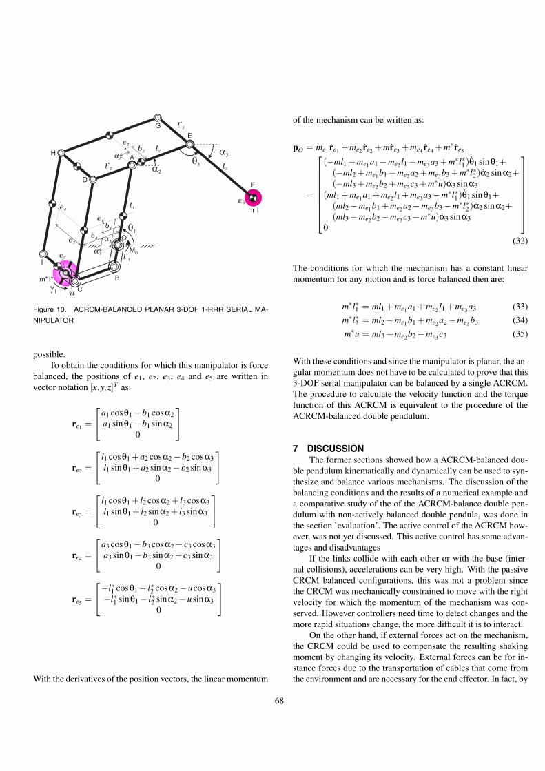
O
l*
1
a2
q1
C
D
E
l3
e5
e2
q3
-a3
F
G
H
I
b1
a3
b3
e4
Bm* I*
g1 u
e3
l*
3
l2
m I
e1
c3
a1
MO
A
b2
a2
l1
l*
2
Figure 10. ACRCM-BALANCED PLANAR 3-DOF 1-RRR SERIAL MA-NIPULATOR
possible.To obtain the conditions for which this manipulator is force
balanced, the positions of e1, e2, e3, e4 and e5 are written invector notation [x,y,z]T as:
re1 =
a1 cosθ1−b1 cosα2a1 sinθ1−b1 sinα2
0
re2 =
l1 cosθ1 +a2 cosα2−b2 cosα3l1 sinθ1 +a2 sinα2−b2 sinα3
0
re3 =
l1 cosθ1 + l2 cosα2 + l3 cosα3l1 sinθ1 + l2 sinα2 + l3 sinα3
0
re4 =
a3 cosθ1−b3 cosα2− c3 cosα3a3 sinθ1−b3 sinα2− c3 sinα3
0
re5 =
−l∗1 cosθ1− l∗2 cosα2−ucosα3−l∗1 sinθ1− l∗2 sinα2−usinα3
0
With the derivatives of the position vectors, the linear momentum
of the mechanism can be written as:
pO = me1 re1 +me2 re2 +mre3 +me4 re4 +m∗re5
=
(−ml1−me1 a1−me2 l1−me3 a3 +m∗l∗1)θ1 sinθ1+(−ml2 +me1 b1−me2a2 +me3b3 +m∗l∗2)α2 sinα2+(−ml3 +me2 b2 +me3c3 +m∗u)α3 sinα3
(ml1 +me1a1 +me2 l1 +me3a3−m∗l∗1)θ1 sinθ1+(ml2−me1b1 +me2a2−me3b3−m∗l∗2)α2 sinα2+(ml3−me2b2−me3c3−m∗u)α3 sinα3
0
(32)
The conditions for which the mechanism has a constant linearmomentum for any motion and is force balanced then are:
m∗l∗1 = ml1 +me1 a1 +me2 l1 +me3 a3 (33)m∗l∗2 = ml2−me1 b1 +me2a2−me3 b3 (34)m∗u = ml3−me2 b2−me3c3 (35)
With these conditions and since the manipulator is planar, the an-gular momentum does not have to be calculated to prove that this3-DOF serial manipulator can be balanced by a single ACRCM.The procedure to calculate the velocity function and the torquefunction of this ACRCM is equivalent to the procedure of theACRCM-balanced double pendulum.
7 DISCUSSIONThe former sections showed how a ACRCM-balanced dou-
ble pendulum kinematically and dynamically can be used to syn-thesize and balance various mechanisms. The discussion of thebalancing conditions and the results of a numerical example anda comparative study of the of the ACRCM-balance double pen-dulum with non-actively balanced double pendula, was done inthe section ’evaluation’. The active control of the ACRCM how-ever, was not yet discussed. This active control has some advan-tages and disadvantages
If the links collide with each other or with the base (inter-nal collisions), accelerations can be very high. With the passiveCRCM balanced configurations, this was not a problem sincethe CRCM was mechanically constrained to move with the rightvelocity for which the momentum of the mechanism was con-served. However controllers need time to detect changes and themore rapid situations change, the more difficult it is to interact.
On the other hand, if external forces act on the mechanism,the CRCM could be used to compensate the resulting shakingmoment by changing its velocity. External forces can be for in-stance forces due to the transportation of cables that come fromthe environment and are necessary for the end effector. In fact, by
68

actively driving the CRCM there are two separate mechanisms.The linkage is one mechanism and the ACRCM is a separatemechanism of which the shaking moment can be controlled suchthat it balances (or compensates) the shaking moment of the forcebalanced linkage.
Drift of the angular velocity of the ACRCM could influencethe moment balance of the mechanism. For instance if the actu-ator is controlling the velocity of the ACRCM and without inputof the actuator the ACRCM is already rotating with a constantvelocity (offset). A constant velocity itself does not influence themoment balance, since the angular momentum then is constant.However, to reach a prescribed velocity of the ACRCM, the ac-celeration will be different and hence the applied torque will notcompensate the shaking moment and will lead to unbalance.
This problem does not occur when the ACRCM is drivenby controlling the torque applied to the ACRCM. If the torqueapplied to the ACRCM is as prescribed, the angular velocity ofthe ACRCM is not of importance. Since the torque balances theshaking moment, the ACRCM can rotate with any velocity offset.
Another advantage of an ACRCM by using a prescribedtorque is the ability to compensate for the elasticity, e.g. the elas-ticity of the belts of the transmissions. Due to this elasticity theacceleration of the ACRCM lags. However since the prescribedtorque already balances the shaking moment, this does not any-more matter.
Experiments on these subjects will be the topic of future re-search, with the aim to build a prototype of a ACRCM-balanceddouble pendulum and test it.
8 CONCLUSIONThis article proposed to force balance mechanisms with
the minimum number of counter-masses and use the inertia ofthese counter-masses for the moment balance by actively con-trolling their rotations. It was shown how a single actively drivencounter-rotary counter-mass (ACRCM) can be used to dynami-cally balance a double pendulum. The force balance of the com-plete mechanism is obtained by adding a single counter-mass.By having this counter-mass counter-rotate with respect to themechanism with the right angular velocity, the moment of themechanism is balanced. The angular velocity of the ACRCMis controlled by an additional actuator which is mounted on thebase.
The velocity-function and the torque-function of the actuatorwere calculated. The ACRCM-principle was compared to otherbalancing principles and by using the ACRCM-balanced doublependulum as building element, various useful ACRCM-balanced1-, 2-, and 3-degree-of-freedom planar and spatial, serial and par-allel mechanisms were synthesized.
The relation between the total mass and the reduced inertiaof the ACRCM-principle is better than balancing with nonac-tive counter-rotary counter masses or with counter-masses and
separate counter-rotations. A trade off between the addition ofmass and the addition of inertia remains also for the ACRCM-principle. The relation between the total mass and the reducedinertia by duplicating the mechanism still is better, however theACRCM-principle can be improved by changing the design ofthe ACRCM. In addition, the size of the balanced mechanismwith an ACRCM is considerably smaller than by duplicating themechanism.
Another advantage of the ACRCM-principle is the abilityto compensate for disturbances that effect the moment balance.By controlling the applied torque to drive the ACRCM, drift andinfluence of elasticity within the transmission do not cause un-balance. Disadvantages are the addition of a controlled actuatorand difficulties for high accelerations as for example occur dueto impact.
A planar 3-RRR parallel manipulator and a 3-DOF planar 1-RRR serial manipulator were dynamically balanced with a singleACRCM. A spatial 3-RRR parallel manipulator was dynamicallybalanced with two ACRCMs.
NOMENCLATUREI inertiaIred reduced inertiam massl link lengthα absolute angle of link with respect to reference frameθ relative angle between two linksγ ACRCM angler position vectord gear diametere COM of a combination of masses(.)∗ balance propertypO linear momentum about the originhO angular momentum about the origink transmission ratioT mechanism’s kinetic energyM applied torqueMsh shaking moment
REFERENCES[1] Van der Wijk, V., Herder, J. L., and Demeulenaere, B.,
2008. “Comparison of various dynamic balancing prin-ciples regarding additional mass and additional inertia”.MSc-Thesis TU-Delft.
[2] Kamenskii, V. A., 1968. “On the question of the balancingof plane linkages”. Journal of Mechanisms, 3, pp. 303–322.
[3] Berkof, R. S., 1973. “Complete force and moment balanc-ing of inline four-bar linkages”. Mechanism and MachineTheory, 8, pp. 397–410.
69

[4] Berestov, L. V., 1975. “Full dynamic balancing of ar-ticulated four-link chain”. Izv. Vyssh. Uchebn. Zaved.-Mashinostroenic, 11, pp. 62–65. (Russian).
[5] Herder, J. L., and Gosselin, C. M., 2004. “A counter-rotarycounterweight (CRCW) for light-weight dynamic balanc-ing”. Proceedings of DETC 2004, ASME,(DETC2004-57246).
[6] Van der Wijk, V., and Herder, J. L., 2008. “Comparativeanalysis and optimization for low-mass and low-inertia dy-namic balancing of a 1-DOF rotatable link balanced by acounter-rotary counter-mass”. MSc-Thesis TU-Delft.
[7] Lowen, G. G., and Berkof, R. S., 1968. “Survey of investi-gations into the balancing of linkages”. Journal of Mecha-nisms, 3, pp. 221–231.
[8] Hilpert, H., 1968. “Weight balancing of precision mechan-ical instruments”. Journal of Mechanisms, 3, pp. 289–302.
[9] VDI2149, 1999. “Blatt 1: Getriebedynamik-starrkorpermechanismen (dynamics of mechanisms-rigid body mech-anisms)”. Verein Deutscher Ingenieure - Richtlinien.
[10] Tsai, L. W., and Roth, B., 1972. “Design of dyads with he-lical, cylindrical, spherical, revolute and prismatic joints”.Mechanism and Machine Theory, 7, pp. 85–102.
[11] Van der Wijk, V., and Herder, J. L., 2008. “Dou-ble pendulum balanced by counter-rotary counter-massesas useful element for synthesis of dynamically bal-anced mechanisms”. Proceedings of DETC 2008, ASME(accepted),(DETC2008-49402).
[12] Menschaar, H. F., Ariens, A. B., Herder, J. L., and Bakker,B. M., 2006. Five-bar mechanism with dynamic balanc-ing means and method for dynamically balancing a five-barmechanism, patent number: W0 2006/080846.
[13] Wu, Y., and Gosselin, C. M., 2007. “On the dynamicbalancing of multi-dof parallel mechanisms with multi-ple legs”. Journal of Mechanical Design, 129, February,pp. 234–238.
70

CHAPTER 7-
DISCUSSION
71
DISCUSSION
Classification of Dynamic Balancing PrinciplesThe principles that were used for complete dynamic balancing of mechanisms in this thesis, are
known for some time already. They originate from around the 60’s and 70’s of the last century. Dur-ing the 80’s and 90’s their application for balancing of mechanisms has been widely explored. Frommostly planar mechanisms until the mid 90’s up to spatial manipulators nowadays, the principlesfor complete dynamic balancing are still ’state of the art’, although this expression may not soundsuitable.
In chapter 2 these balancing principles were classified as (A) balancing links individually and(B) balancing mechanisms altogether (i.e. not link by link). Balancing links individually was doneby using counter-masses for the force balance and separate counter-rotations (SCR) for the momentbalance or by using the counter-masses also for the moment balance by having them counter-rotate(the counter-rotary counter-mass (CRCM-) principle). Balancing mechanisms altogether was doneby duplicating the mechanism (DM). But is this classification at the end of this thesis still appropri-ate?
In chapters 4 and 5, balancing configurations were found that are a combination of class (A) andclass (B). In chapter 4 it was shown that the moment of a double pendulum (two degrees of freedom)could be balanced with one CRCM. The links were force balanced individually (class (A)) but themoment of the complete mechanism was balanced altogether (class (B)). In chapter 5, configurationswere found in which the complete mechanism was balanced altogether with a single CRCM and alsoin chapter 6, where a single actively driven CRCM (ACRCM) was used to obtain dynamic balance.Therefore, complete dynamic balancing with CRCMs belongs to both class (A) and (B). Since atleast for some of these both class (A) and class (B) CRCM-balanced configurations the CRCM canbe replaced with a counter-mass and a separate counter-rotation, the SCR-principle also belongs toboth classes.
In chapter 5, configurations were obtained in which force balanced counter-rotating links wereused to balance the mechanism. These links, with a specific inertia, are kinematically constrainedto move such that no CRCM or SCR is needed to obtain dynamic balance. In addition, the DM-principle is based on balancing with counter-rotating (not force-balanced) links. Balancing by usingcounter-rotating links (CRLs) is a balancing principle that was not classified yet.
Therefore, the classification of chapter 2 needs a revision and a revised classification is shownin Figure. 1. The three essential dynamic balancing principles are dynamic balancing by (i) counter-masses and SCRs, (ii) CRCMs, and (iii) counter-rotating links. These are the principles with whichmechanisms can be dynamically balanced; link by link or (parts of) the mechanism altogether.
MethodThroughout this thesis, the conservation of momentum method, the equations of the linear and
angular momentum as described in chapter 2, has shown to be a powerful tool for the calculationsof the conditions for which mechanisms are force balanced and moment balanced. These conditionsare obtained within a few calculation steps.
72

dynamic balancing
counter-rotarycounter-masses
counter masses andseparate counter-rotations
counter-rotatinglinks
balancing linksindividually
balancing mechanism(parts) together
Figure 1. THREE BALANCING PRINCIPLES TO BALANCE MECHANISM WITH; LINK BY LINK OR (PARTSOF) THE MECHANISM ALTOGETHER
SynthesisIn chapter 2, the double pendulum was found to be an important building element for the syn-
thesis of a variety of mechanisms. Equivalently, with a dynamically balanced double pendulum, avariety of dynamically balanced mechanisms can be synthesized. This was shown in chapters 4 and6 where balanced 1-, 2- and 3-degree of freedom planar and spatial, serial and parallel mechanismswere obtained. The crank-slider mechanisms of chapter 5 also include a double pendulum. Thesecrank-slider mechanisms were dynamically balanced after the motion of the double pendulum wasconstrained, by which it became possible to have configurations without a counter-mass or CRCMat the coupler link.
In chapter 6 a planar ’triple pendulum’ (tree-link) was dynamically balanced with a singleACRCM. If the endpoint of this serial manipulator would be connected to the base by a joint, ageneral 4R four-bar mechanism would be obtained, balanced by a single ACRCM. The usefulnessof this balanced triple pendulum still needs attention. It might turn out to be as useful in the synthe-sis of balanced mechanisms as the double pendulum, however due to the additional parallel links,the configuration is rather complex.
Comparative StudyA comparative study of the balancing principles was carried out in the chapters 2, 3 and 6.
In chapter 3 the CRCM-principle, SCR-principle and DM-principle were analyzed into detail byapplying them to a 1-degree of freedom rotatable link. In chapter 2 these principles were applied toa double pendulum. Also balancing by using an idler loop was investigated, in which two auxiliarylinks ar added to the double pendulum to transfer the rotational motion of the outer link to the base,where the moment of this link is balanced with a separate counter-rotation. In chapter 6 a doublependulum was balanced with a single ACRCM, comparable to the double pendula in chapter 2.
For the comparative study with the 1-degree of freedom rotatable link in chapter 3, the optimalconfiguration for each balancing principle was determined by the Mass-Inertia (MI-) factor, whichwas introduced in chapter 2. This factor is the weighted sum of increase of mass and the increaseof inertia. The optimal parameters for each balancing principle were obtained for the lowest MI-factors and these MI-factors were compared. The comparison of the balanced double pendula inchapters 2 and 6 however was only done for some chosen configurations. The choice was basedon the transmission (gear) ratios for which practical values were chosen. The comparison was alsolimited by the positions of the counter-masses, which were equal for all principles.
Nevertheless, the results that were obtained for the comparative study of the balanced doublependula match with the results of the detailed analysis in chapter 3. A detailed analysis also forthese balanced double pendula is still something that needs to be done to find the parameters forwhich they are optimal. Also dynamic balancing by using counter-rotating links is not analyzed andcompared yet.
73

Counter-Rotary Counter-Mass as Preferred Balancing ConfigurationThroughout this thesis, mainly CRCMs have been used for the dynamic balance of the newly
derived mechanisms. There are two reasons for this. Firstly, the comparative studies showed thatthe use of CRCMs is better for low-mass and low-inertia dynamic balancing than their equivalentswith separate counter-masses and SCRs. Secondly, by using a single element for both the force andmoment balance, the drawings of the balanced mechanisms are more clear then if separate counter-rotations are used. This makes it easier to study and to find new balanced mechanisms.
The basic CRCM-configuration with which a double pendulum was balanced was given inchapter 2 (Chapt. 2, Fig. 3). In this configuration, the outer link is force and moment balancedwith a CRCM that is driven by a gear, which is attached to the other moving link. The completemechanism is balanced with respect to the base with another CRCM which is driven by a gear thatis attached to the base.
By changing the position and construction of the gears, from this basic CRCM-configurationnew CRCM-configurations were derived in chapter 4. These were characterized by having a lowerinertia, having a single CRCM instead of two, and with all CRCMs located near the base.
This last configuration formed the basis of chapter 5. Counter-masses that are not near the base(not at the base or at the links connected to the base) need to be balanced by other counter-masseswhich are near the base which leads to a considerable increase of additional mass. By bringing allcounter-masses near the base the addition of mass is reduced.
SimilaritiesThe resulting configurations in chapter 5 turn out to have similarity with the DM-principle. The
links that were added to the initial crank-slider mechanism were used to copy the motion of thecoupler link. Configuration were found that were balanced without the use of CRCMs or SCRs. Thecounter-rotating links (CRLs) were suitable for the complete dynamic balance.
These counter-rotating links can also be seen as special separate counter-rotations. The inertiaof a gear driven SCR, and also of a CRCM, depends on the choice of the transmission ratio. Sincethe motion of a CRL is already determined by its kinematics, its inertia is determined too. Instead ofusing CRLs as separate counter-rotations, the counter-rotating links could also be used as counter-masses. Then the CRL becomes a CRCM with the geometry of a link.
The interesting point to make here, is that the comparative studies of chapters 2 and 3 showedthat the DM-principle is the principle with the lowest addition of mass and the lowest additionof inertia of all principles. In chapter 3 it was found that this was because of its relatively largesize and its small transmission ratio of -1 with respect to the use of counter-rotations. In chapter5, counter-rotations and link duplication together, the counter-rotating links, resulted into smallerbalanced configurations with also a transmission ratio of -1. Therefore it can be assumed that theseconfigurations have a performance in between the DM- and CRCM-principle, an addition of massand inertia that is lower than the CRCM-principle. However a comparative study still needs to bedone to show this.
Guidelines for Low-Mass and Low-Inertia Dynamic BalancingBy bringing together the results of this thesis, guidelines for the design of low mass and low
inertia dynamically balanced mechanisms are obtained. From the results with balancing by usingCRCMs and CRLs, it is found that all elements of the mechanism, including links, counter-masses,and counter-rotary counter-masses, have to contribute to both the force balance and the momentbalance of the mechanism for any motion of the mechanism. For existing mechanisms this appliesto the additional elements while for the design of new mechanisms it applies to all elements. Mech-anism links have to be positioned such that they counter-rotate with other links which means thatdynamic balancing already starts within the kinematics of the unbalanced mechanism. CRCMs haveto be used instead of SCRs since this results in less addition of mass and less addition of inertia.
74

m* I*
O
k
m I
l*
l
q
Design Space& Work Space
CRCM
Figure 2. WITHIN THE DESIGN SPACE THE MAXIMAL DIMENSIONS OF THE CRCM DEPEND ON THELENGTH l∗; THE LARGER THE CRCM THE SMALLER THE ADDITIONAL INERTIA; THE FURTHER THEPOSITION OF THE CRCM IS AWAY FROM O, THE SMALLER THE ADDITION OF MASS AND THE LARGERTHE INERTIA; THEREFORE THERE IS A TRADE OFF BETWEEN ADDITION OF MASS AND ADDITION OFINERTIA
In chapter 3 it was shown that for a low mass addition, counter-masses have to be placed faraway from their center of rotation and from chapter 4 that the counter-masses have to be placednear the base, i.e. at the base or at the link connected to the base. For the minimal addition ofinertia, counter-masses have to be placed close to their center of rotation and, if not useful for themoment balance, have a small inertia. The former is however contradictory with the rule for lowmass addition. This implies that there is a trade off between the addition of mass and the addition ofinertia. The relative importance of each for the intended purpose must be chosen.
For a low addition of inertia, CRCMs have to have a large inertia and a low transmission ratio.For a large inertia, the dimension of a CRCM must be large. This implies that for a low mass andlow inertia addition the design space should be as large as possible. The design space is the spacethat is available for the balancing elements, which is illustrated for a 1-DOF rotatable link in Fig. 2.Here the design space was chosen to be the circumscribed circle of the link, which could be theworkspace of the mechanism in case it can fully rotate.
75

As a summary, the guidelines for the design of low-mass and a low-inertia dynamically bal-anced mechanisms are formulated as:
Minimal addition of mass and minimal addition of inertia
> For a minimal addition of mass and inertia, all elements of the mechanism including links,counter-masses, and counter-rotary counter-masses have to contribute to both the force balanceand the moment balance of the mechanism for any motion of the mechanism. For existingmechanisms this applies to the additional elements while for the design of new mechanisms itapplies to all elements. Mechanism links have to be positioned such that they counter-rotatewith other links which means that dynamic balancing already starts within the kinematics of theunbalanced mechanism.
> For minimal addition of mass and inertia, the design space of the mechanism that is availablefor the position and the motion of balancing elements has to be maximal.
> For minimal addition of mass and inertia, the use of separate counter-rotations must be omitted.
Minimal addition of mass
> For minimal addition of mass, counter-masses and counter-rotary counter-masses have to beplaced at maximum distance from their center of rotation.
> For minimal addition of mass, the balancing elements (counter-masses, counter-rotary counter-masses, counter-rotating links) have to be positioned at the base or at the links that are connectedto the base or such that they do not need to be balanced by other counter-masses.
Minimal addition of inertia
> For minimal addition of inertia, counter-masses and counter-rotary counter-masses have to beplaced at minimum distance from their center of rotation.
> For minimal addition of inertia, counter-masses that are fixed to their link and elements that donot contribute to the moment balance must have minimal inertia.
> For minimal addition of inertia, geared counter-rotating elements themselves must have maxi-mal inertia.
> For minimal addition of inertia, the gear- and transmission ratios of the counter-rotating ele-ments have to be minimal.
Minimal addition of mass or inertia
> A trade-off between the addition of mass and the addition of inertia must be made. The designerhas to decide the relative importance of each for the intended purpose.
Design SpaceIn Fig. 2, a 1-DOF rotatable link with length l is shown, which has a lumped mass m with inertia
I at its end. For the force balance of this link a CRCM with mass m∗ and inertia I is placed at thelink at a distance l∗ from the center of rotation O. For the moment balance the CRCM is driven by abelt with a gear attached to the CRCM and a gear at O that is mounted on the base and cannot rotate.As long as the gear at the CRCM is smaller than the gear at O, the CRCM will counter-rotate withrespect to the link and is able to balance the moment of the link.
The design space is an extra restriction on the design, which was not studied in this thesis. Theelements necessary for balancing must stay within the design space. For a low inertia addition, theCRCM in Fig. 2 must have a large inertia, which is obtained if its diameter is large. However, by anincreasing diameter of the CRCM, the distance l∗ becomes smaller. This means that the addition ofmass increases while the inertia of the mechanism decreases even more.
76

m* I*
k
m I
l*
l
q
Design Space
Work Space
O
CRCM
Figure 3. IN REAL MACHINES THE RELATION BETWEEN THE ADDITIONAL MASS AND THE ADDITIONALINERTIA IS INFLUENCED BY THE DESIGN SPACE; IN THIS CASE THE MAXIMUM DIAMETER OF THE CRCMIS DRAWN, REDUCING LENGTH l∗ DECREASES THE CRCM-DIAMETER BY WHICH THE INERTIA OF THEMECHANISM INCREASES
In practice, the design space will depend on the available space within the machine, for instanceas illustrated in Fig. 3. The motion of the mechanism is limited, but the link should be able to reachthe extremities of the defined workspace. In this situation it turns out that reducing length l∗ doesnot result into a larger possible diameter of the CRCM. In Fig. 3 the position for the maximumdiameter of the CRCM is drawn. Reducing or increasing length l∗ results into smaller dimensionsof the CRCM, which implies that their exists an optimum for the additional inertia.
In practice also the addition of mass will have an optimum, since the properties of the link thatcarries the CRCM (material, dimensions, a.o.) are limited too. It is likely that by including these andother boundary conditions (e.g. including also the third dimension), optimal designs can be foundin many applications, leading to low mass and low inertia dynamically balanced machines.
ClosureIt is interesting for future research to combine the knowledge for low mass and low inertia
dynamic balancing with the boundary conditions of reality and subsequently bring machines intodynamic balance.
77

CHAPTER 8-
CONCLUSION
78

CONCLUSION
Demands for high accuracy in combination with high production speeds (low cycle times) inindustry, and accurate position control of manipulators in free space, have been the lead for thesearch for solutions where mechanism vibrations are minimal and the addition of mass and inertiais low. Completely dynamically balanced mechanisms were found suitable, since vibrations due tothe mass and inertia of mechanism elements are eliminated.
Complete dynamic balancing principles were analyzed regarding their addition of mass andtheir addition of inertia. The Mass-Inertia (MI-) factor was proposed to find optimal mechanismconfigurations. The different balancing principles were compared and were classified as (i) forcebalancing with counter-masses and moment balancing with separate counter-rotations (SCRs); (ii)force and moment balancing by counter-rotary counter-masses (CRCMs) where the counter-mass isalso used as counter-rotation; (iii) force and moment balancing by counter-rotating links (CRLs).
The conservation of linear and angular momentum was found to be the most general approachand powerful for the calculation of the conditions for which a mechanism is force balanced andmoment balanced, respectively. The linear and angular momentum equations were also found usefulto derive the equations of the inertia of the mechanism.
A balanced double pendulum was considered to be an important building element in de synthe-sis of various dynamically balanced 1-, 2-, and 3-degree-of-freedom planar and spatial, serial andparallel mechanisms. Useful new balanced mechanisms were found.
Various different configurations of dynamic balancing with CRCMs were found, with featuressuch as a reduced number of CRCMs, only CRCMs at the crank or at the base, and with an especiallylow inertia. It was found that planar mechanisms of which the center-of-mass can be materialized,can be completely dynamically balanced with one actively (by an extra actuator) driven CRCM.
Guidelines for the design of low-mass and low-inertia dynamically balanced mechanisms wereformulated. These provide clear directions if either low mass or low inertia is pursued, but where atrade-off needs to be made if both low mass and low inertia are desired.
79

APPENDICES
80

APPENDIX A-
EFFECT OF BELT ELASTICITY ON THE DYNAMICBALANCE OF A COUNTER-ROTARY
COUNTER-MASS BALANCER
81

EFFECT OF BELT ELASTICITY ON THE DYNAMICBALANCE OF A COUNTER-ROTARY COUNTER-MASS
BALANCER
ABSTRACTThis document investigates the influence of the use of a visco-elastic POLYCORD belt
on the dynamic balance of a physical model of a 1-DOF rotatable link, dynamically bal-anced by using a Counter-Rotary Counter-Mass (CRCM). The aim is to find out if theCRCM can be driven with an elastic belt such that the dynamic balance is maintained.Therefore the frequency dependent stiffness of the POLYCORD belt is determined by mea-surements. By using Newton’s and Euler’s laws of motion, the system of equations of mo-tion is derived. This leaded to a good understanding of how the balanced model works.For both an applied harmonic excitation of the link and an applied harmonic moment to thelink the solutions are found. This shows that due to the elasticity for any frequency of thelink, complete dynamic balance is not possible. For low frequencies deviation from com-plete dynamic balance is little, but for high frequencies the balancing effect of the CRCMvanishes completely.
1 INTRODUCTIONDynamic balance is an useful and often an important feature of a machine. For machines moving
in space - helicopters, spacecrafts, satellites e.g. - it is necessary that the body or base is balancedto maintain its orientation. For robotics balancing is important to allow quick manoeuvring with ahigh accuracy. The base doesn’t vibrate by which floors of factories can be designed lighter andmachines that are connected to the same base do not influence each other. For hand tools dynamicbalance improves the ergonomics and hence reduces the risk of injuries of the user.
One major problem by balancing a mechanism is the necessary mass and inertia that must beadded which is generally much. The mass of the initial mechanism must first be force balanced bya counter-mass. Then this force balanced mechanism must be moment balanced by using a counter-inertia which is often an additional part with a certain mass. The advantage of the CRCM-principlehowever is that it uses the counter-mass also as counter-inertia for which an additional part is omittedand therefore the additional mass is less.
A CRCM can be driven by for example spur gears, planetary gears or a belt transmission. Dueto backlash, the dynamic balance of a mechanism by using gears cannot be maintained. If this alsoholds for the elasticity of the belt is to find out in this document.
82

Figure 1. Dynamically balanced mechanism model with a CRCM
The aim of this document is to find out if a CRCM can be driven with an elastic belt such thatthe dynamic balance is maintained.
A CRCM-balanced 1-DOF rotatable link is modeled to have a visco-elastic belt. For this modelthe system of equations of motion is derived in section 2. For both an applied harmonic excitationof the link and an applied harmonic moment to the link the solutions are derived. In section 3the measurements are done and the parameters of the POLYCORD belt are obtained. With theseparameters in section 4 a time simulation of the 1-DOF rotatable link is carried out and the resultsare given. Finally the discussion and conclusion are presented in section 5.
Aq
1
l1
l2
m1 I1
m2 I2
Figure 2. KINEMATIC MODEL OF A CRCM-BALANCED 1-DOF ROTATABLE LINK; LINK l1 WITH m1 IS THELINK BEFORE BALANCING WITH PAYLOAD, CRCM m2 WITH I2 IS ADDED AT A DISTANCE l2 AND ISDRIVEN BY A BELT WHICH IS ATTACHED TO A GEAR AT THE CRCM AND A GEAR AT A. THE GEARAT A IS FIXED TO THE BASE AND CANNOT ROTATE
2 DYNAMIC MODELThis section starts with deriving the system of equations of motion from the free body diagrams
of the mechanism. Drawing all the forces and using Newton’s and Euler’s laws of motion, force
83

equals mass times linear acceleration and moment equals inertia times rotational acceleration re-spectively, leads to a good understanding of the way the balanced mechanism works. Then solutionsfor two cases are exploited. First the case of an applied excitation of the link for which the magni-fication factor and the phase difference are calculated. Second the case of an applied moment ontothe link for which the reaction moments on the base are calculated. For the easy of calculation, thelinkage is assumed to be in an environment without any conservative force field, e.g. gravity. Thisis possible since constant forces do not influence the dynamic balance of a mechanism.
A
q1
Fn,2
Fa,2
M
Fn,B
Fa,B
n,1
a,1
m1 I
1
l1
l2
Figure 3. Free body diagram of the link
r2
S1
S2
a
a
b
b
q1
Fn,2
Fa,2
n,2
a,2
q2
m2I
2
Figure 4. Free body diagram of the CRCM
2.1 System of Equations of MotionFrom Figure 3 the equations of motion for the link can be written as:
m1 0 00 m1 00 0 I1 +m1l2
1
·
a1n1θ1
=
Fa2 −FaB
Fn2 −FnB
M−Fn2 l2
(1)
by which the mass and the inertia of the link are included in m1 and I1 and a1 and n1 represent theco-ordinate system moving with the link and having its origin in the center of rotation. M is the
84

Aq
1
S1
S2
r1
n,B
a,B
Fn,R
Fa,R
Fn,B
Fa,B MR
M
a
a
b
b
mBI
B
Figure 5. Free body diagram of the base
applied moment by the actuator which is mounted on the base and exerts a moment onto the link.The equations of motion for the CRCM can be obtained from Figure 4:
m2 0 00 m2 00 0 I2
·
a2n2θ2
=
−Fa2 +(S1 +S2)cosβ−Fn2 +(S1−S2)sinβ
(S2−S1)r2
(2)
Here a2 and n2 represent the moving co-ordinate system with its origin at the center of the CRCMand S1 and S2 are the forces in each part of the belt. From Figure 5 the equations of motion of thebase write:
mB 0 00 mB 00 0 IB
·
aBnBθB
=
FaR +FaB − (S1 +S2)cosβFnR +FnB +(S2−S1)sinβ
MR−M +(S1−S2)r1
(3)
In which MR is the reaction moment that must be applied to maintain the base stationary. Com-bining the matrices (1), (2) and (3) results into the system of equations of motion of the completemechanism:
m1 . . . . . . . .. m1 . . . . . . .. . I1 +m1l2
1 . . . . . .. . . m2 . . . . .. . . . m2 . . . .. . . . . I2 . . .. . . . . . mB . .. . . . . . . MB .. . . . . . . . IB
·
a1n1θ1a2n2θ2aBnBθB
=
Fa2 −FaB
Fn2 −FnB
M−Fn2 l2−Fa2 +(S1 +S2)cosβ−Fn2 +(S1−S2)sinβ
(S2−S1)r2FaR +FaB − (S1 +S2)cosβFnR +FnB +(S2−S1)sinβ
MR−M +(S1−S2)r1
The kinematic relations within the mechanism are:
a2 = a1 = aB (4)n2 = n1− θ1l2 (5)n1 = nB (6)
85

a ar
2
r1
b
b
l2
Figure 6. Angles α and β
Assuming that all masses and inertias are known and also the applied moment M leads to a total of 13equations and 16 unknowns. If the base is assumed to be fixed then aB = nB = θB = 0 and the systemof equations can be solved. If the base is assumed to be floating in space then FaR = FnR = MR = 0and the system of equations can be solved too. In the remaining the base will be assumed to be fixed.Then the system of equations of motion writes:
m1 . . . . . . . .. m1 . . . . . . .. . I1 +m1l2
1 . . . . . .. . . m2 . . . . .. . . . m2 . . . .. . . . . I2 . . .. . . . . . mB . .. . . . . . . MB .. . . . . . . . IB
·
00θ10n2θ2000
=
Fa2 −FaB
Fn2 −FnB
M−Fn2 l2−Fa2 +(S1 +S2)cosβ−Fn2 +(S1−S2)sinβ
(S2−S1)r2FaR +FaB − (S1 +S2)cosβFnR +FnB +(S2−S1)sinβ
MR−M +(S1−S2)r1
(7)
Picking out the nonzero equations from (7) and substituting n2 =−θ1l2 from (5) and (6) results into:
I1 +m1l21 0 0
0 I2 00 0 m2
·
θ1θ2
−θ1l2
=
M−Fn2 l2(S2−S1)r2
−Fn2 +(S1−S2)sinβ
(8)
With the third relation of (8) Fn2 can be written as:
Fn2 = m2θ1l2 +(S1−S2)sinβ (9)
From Figure 6 sinβ can be calculated:
sinβ = sin(π2−α) = cosα =
r1− r2
l2(10)
Then substituting Fn2 in the first expression of (8) finally results into the following small form of theequations of motion:
[I 00 I2
]·[
θ1θ2
]=
[M− (S1−S2)(r1− r2)
(S2−S1)r2
](11)
86

with I = I1 + m1l21 + m2l2
2 . The reaction or ’shaking’ moment MR can be obtained from the lastequation in (7):
MR = M− (S1−S2)r1 (12)
which is zero for a balanced mechanism if:
M = (S1−S2)r1 (13)
Substituting (13) in (11) results into:
[I 00 I2
]·[
θ1θ2
]=
[−(S2−S1)r2(S2−S1)r2
]
and shows that for a dynamic balanced system must hold that:
Iθ1 =−I2θ2 (14)
or:
I =−kI2 (15)
with k = θ2θ1
being the transmission ratio. For the force balance must hold that m1l1 = m2l2 for whichthe center of mass is stationary. The reason that this is not visible from the equations of motion isthe choice for the moving co-ordinate system. However this choice reduces the size of the equationsfavorably.
For harmonic stress and strain functions within the cord, the belt forces S1 and S2 can be easilycalculated as:
S1 = σA = E∗εA = E∗41 fg (16)S2 = E∗42 fg (17)
with E∗ being the frequency dependent elasticity of the cord which can be complex to allow a phasedifference and with the belt elongations:
41 = r2θ2 +(r1− r2)θ1 (18)42 = −41 =−r2θ2− (r1− r2)θ1 (19)
The geometric factor fg for a cylindric object exerted to tensile forces in longitudinal direction is
written as fg = π(d/2)2
` , with d and ` being its diameter and length respectively. With:
(S1−S2) = 2E∗ fg41 (20)
the equations of motion of (11) can be rewritten as:
[I 00 I2
]·[
θ1θ2
]=
[M−2E∗ fg41(r1− r2)
−2E∗ fg41r2
](21)
87

2.2 Applied ExcitationIf the link is harmonically excitated by θ1 = S0eiωt , then θ2 can be solved from the second
differential equation of (21) directly. Assuming for θ2 a harmonic solution of θ2 = b∗eiωt , by whichb∗ can be a complex number to allow phase differences, by substituting it into the second equationof (21) and dividing by eiωt yields:
−ω2I2b∗ =−2E∗ fgr2(r2b∗+(r1− r2)S0) (22)
Rearranging for b∗ leads to:
b∗ =−2S0E∗ fgr2(r1− r2)−ω2I2 +2r2
2E∗ fg
=−(r1− r2)S0
r2
2E∗ fgr2
2E∗ fgr2− ω2I2r2
(23)
The frequency dependent elasticity can be written in complex form as:
E∗ = E ′+ iE ′′
= E ′(1+ i tanδ) (24)
in which E ′ and E ′′ represent the real and imaginary part of E∗ and tanδ = E ′′E ′ represents the phase
difference of the cord. From (16) it is clear that E∗ fg must represent the stiffness K∗ of the cord andhence it follows that:
K′ = fgE ′ (25)K′′ = fgE ′′ (26)
With (24) and (25), (23) can be rewritten as:
b∗ =−(r1− r2)S0
r2
1+ i tanδ1+ i tanδ− ( ω
ωn)2 (27)
with:
ω2n =
2E ′ fgr22
I2=
2K′r22
I2(28)
The magnification factor M can be calculated as:
M =r2b∗
−(r1− r2)S0=
1+ i tanδ1+ i tanδ− ( ω
ωn)2 (29)
By multiplying M with the complex conjugate of its denominator and rearranging, the real andimaginary parts of M can be separated:
M =1− ( ω
ωn)2 + tan2 δ
(1− ( ωωn
)2)2 + tan2 δ− i
( ωωn
)2 tanδ(1− ( ω
ωn)2)2 + tan2 δ
(30)
88
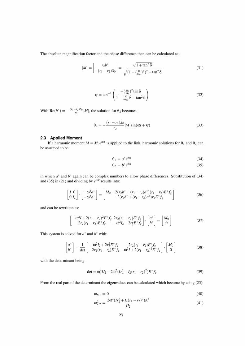
The absolute magnification factor and the phase difference then can be calculated as:
|M|=∣∣∣∣
r2b∗
−(r1− r2)S0
∣∣∣∣ =
√1+ tan2 δ√
(1− ( ωωn
)2)2 + tan2 δ(31)
ψ = tan−1
(−( ω
ωn)2 tanδ
1− ( ωωn
)2 + tan2 δ
)(32)
With Re(b∗) =− (r1−r2)S0r2
|M|, the solution for θ2 becomes:
θ2 =− (r1− r2)S0
r2|M|sin(ωt +ψ) (33)
2.3 Applied MomentIf a harmonic moment M = M0eiωt is applied to the link, harmonic solutions for θ1 and θ2 can
be assumed to be:
θ1 = a∗eiωt (34)θ2 = b∗eiωt (35)
in which a∗ and b∗ again can be complex numbers to allow phase differences. Substitution of (34)and (35) in (21) and dividing by eiωt results into:
[I 00 I2
]·[−ω2a∗
−ω2b∗
]=
[M0−2(r2b∗+(r1− r2)a∗)(r1− r2)E∗ fg
−2(r2b∗+(r1− r2)a∗)r2E∗ fg
](36)
and can be rewritten as:
[−ω2I +2(r1− r2)2E∗ fg 2r2(r1− r2)E∗ fg2r2(r1− r2)E∗ fg −ω2I2 +2r2
2E∗ fg
]·[
a∗b∗
]=
[M00
](37)
This system is solved for a∗ and b∗ with:
[a∗b∗
]=
1det
[ −ω2I2 +2r22E∗ fg −2r2(r1− r2)E∗ fg
−2r2(r1− r2)E∗ fg −ω2I +2(r1− r2)2E∗ fg
]·[
M00
](38)
with the determinant being:
det = ω4II2−2ω2(Ir22 + I2(r1− r2)2)E∗ fg (39)
From the real part of the determinant the eigenvalues can be calculated which become by using (25):
ωn,1 = 0 (40)
ω2n,2 =
2ω2(Ir22 + I2(r1− r2)2)K′
II2(41)
89

The solutions for θ1 and θ2 from (34) and (35) can be written as:
θ1 = |a∗|sin(ωt +ψ1) (42)θ2 = |b∗|sin(ωt +ψ2) (43)
in which:
ψ1 = tan−1(Im(a∗)/Re(a∗)) (44)ψ2 = tan−1(Im(b∗)/Re(b∗)) (45)
To investigate the solutions for a belt with infinite stiffness, from (38) a∗ and b∗ can be writtenas:
a∗ =(−ω2I2 +2r2
2E∗ fg)M0
ω4II2−2ω2(Ir22 + I2(r1− r2)2)E∗ fg
(46)
=(−ω2I2M0 +2r2
2K′M0)+ i(2r22K′M0 tanδ)
(ω4II2−2ω2K′(Ir22 + I2(r1− r2)2))− i(2ω2K′(Ir2
2 + I2(r1− r2)2) tanδ)(47)
b∗ =−2r2(r1− r2)E∗ fgM0
ω4II2−2ω2(Ir22 + I2(r1− r2)2)E∗ fg
(48)
=(−2r2(r1− r2)K′M0)− i(2r2(r1− r2)K′M0 tanδ)
(ω4II2−2ω2K′(Ir22 + I2(r1− r2)2))− i(2ω2K′(Ir2
2 + I2(r1− r2)2) tanδ)(49)
For an inelastic belt holds that K′ −→ ∞ and there will be no phase difference, then tanδ = 0.Calculating the limit situation of a∗ in (47) leads to:
limK′→∞
(a∗) = limK′→∞
(−ω2I2M0 +2r2
2K′M0
ω4II2−2ω2K′ (Ir22 + I2(r1− r2)2
))
=
(2r2
2M0
−2ω2(Ir2
2 + I2(r1− r2)2))
=
M0
−ω2(
I + I2( r1r2−1)2
) (50)
where l’Hopital’s rule was applied and the term(
I + I2( r1r2−1)2
)represents the reduced inertia.
This is the inertia of the mechanism reduced to the input angle θ1, the inertia that the actuator’feels’. From equations (12) and (20) the shaking moment MR can be calculated:
MR = M−2E∗ fg(r2θ2 +(r1− r2)θ1)r1 (51)
Since the phase differences of θ1 and θ2 are already included in a∗ and b∗, only the real part of E∗must be used in this equation. With substition of (34), (35) and (25), (51) writes:
MR ={
M0−2K′r1(r2b∗+(r1− r2)a∗)}
eiωt (52)
90

Working out this equation leads to:
MR = {M0−2K′r1(r2(Re(b∗)−Re(a∗))+ r1Re(a∗))−− (2K′r1(r2(Im(b∗)− Im(a∗))+ r1Im(a∗)))i}eiωt (53)
Then with:
|MR| =√
Re(MR)2 + Im(MR)2 (54)
φ = − tan−1 Im(MR)Re(MR)
(55)
MR finally becomes:
MR = |MR|sin(ωt +φ) (56)
3 MEASUREMENTSThis section describes the measurements to determine the frequency dependent stiffness and its
phase difference of the Ø 4mm polyurethane-elastomer POLYCORD belt. Since this stiffness K canbe calculated by:
K =Fd
sd(57)
in which Fd and sd are the dynamic force on the cord and the dynamic elongation of the cordrespectively, these are the parameters to be measured.
3.1 Measurement setupFor the dynamic measurements on a sample of the POLYCORD the following devices have
been used:
- Metravib Viscoanalyseur VA400 No. 0205121200- Metravib capteur force (force sensor) No. 134250100- Ø4 mm cilindric clamps- datalogger: Compaq Deskpro EP-series 6400/10 NTL, serial No. 8927cck5h43- Dynatest 6.11 (software)
The cylindric clamps were orientated vertically within the Metravib Viscoanalyzer. The lower clampwas fixed onto the force sensor while the upper clamp was fixed to the oscillating part of the machine.By use of the software Dynatest, measurement data were recorded.
3.2 Measurement procedureA sample of the POLYCORD of 42 mm was taken and clamped into the machine by which the
length between the clamps (`0) was 32 mm. A prestress according to a tensile force of 22N wasapplied which represents 8 % of elongation according to the factory specifications for practical use.This is the prestress of the belt when mounted around two pulleys within a machine. To measurethe dynamic stiffness with its phase, the POLYCORD was harmonically excitated by sd sin(ωt) inwhich the dynamic displacement sd was chosen to be 5.0e−5m. The real values of sd were recorded.The measurements were done for the 6 different frequencies 0.1, 0.3, 1, 3, 10 and 30 Hz and with anambient temperature of +21.73◦C. Every measurement was repeated for 6 times.
91
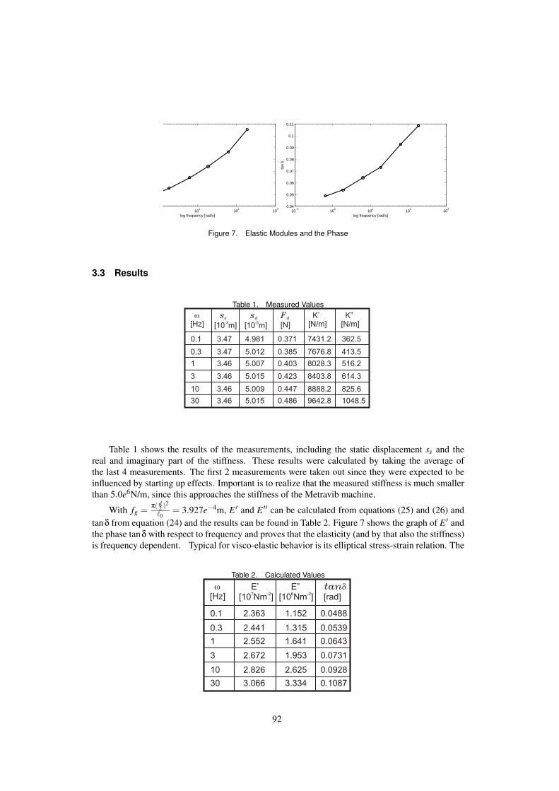
101
102
103
log frequency [rad/s]10
−110
010
110
210
30.04
0.05
0.06
0.07
0.08
0.09
0.1
0.11
log frequency [rad/s]
tan
δ
Figure 7. Elastic Modules and the Phase
3.3 Results
Table 1. Measured Valuesw
[Hz]
0.423
0.385
0.403
0.371
0.447
0.486
3
0.3
1
0.1
10
30
614.3
413.5
516.2
362.5
825.6
1048.5
8403.8
7676.8
8028.3
7431.2
8888.2
9642.8
sd
[10 m]-5
K”[N/m]
K’[N/m]
Fd
[N]
ss
[10 m]-3
5.015
5.012
5.007
4.981
5.009
5.015
3.46
3.47
3.46
3.47
3.46
3.46
Table 1 shows the results of the measurements, including the static displacement ss and thereal and imaginary part of the stiffness. These results were calculated by taking the average ofthe last 4 measurements. The first 2 measurements were taken out since they were expected to beinfluenced by starting up effects. Important is to realize that the measured stiffness is much smallerthan 5.0e6N/m, since this approaches the stiffness of the Metravib machine.
With fg = π( d2 )2
`0= 3.927e−4m, E ′ and E ′′ can be calculated from equations (25) and (26) and
tanδ from equation (24) and the results can be found in Table 2. Figure 7 shows the graph of E ′ andthe phase tanδ with respect to frequency and proves that the elasticity (and by that also the stiffness)is frequency dependent. Typical for visco-elastic behavior is its elliptical stress-strain relation. The
Table 2. Calculated Values
w
[Hz]
0.0731
0.0539
0.0643
0.0488
0.0928
0.1087
3
0.3
1
0.1
10
30
1.953
1.315
1.641
1.152
2.625
3.334
2.672
2.441
2.552
2.363
2.826
3.066
E”[10 ]
6Nm
-2
E’[10 Nm ]
7 -2
tand
[rad]
92

−0.6 −0.4 −0.2 0 0.2 0.4 0.6 0.8 1strain [−]
30 Hz
1 Hz
3 Hz
0.3 Hz
10 Hz
0.1 Hz
Figure 8. Stress-Strain relation
Table 3. Initial Parameters( / -1)r r I
1 2 2
[kgm ]2
r1I
1
S0
M0
9.466*10-4
15/360[ rad]p
0.004
0.4
I2
[kgm ]2
r2
[Nm]
0.032
[m]
[m]
stress and strain relations can be written as:
σ = σ0 sin(ωt) (58)ε = ε0 sin(ωt−δ) (59)
The values for σ0 and ε0 can be calculated as follows.
ε0 =d`
`0=
sd − `0
`0(60)
σ0 =√
E ′2 +E ′′2ε0 (61)
Figure 8 shows the results of the stress-strain relation for different frequencies and indeed niceelliptical Lissajous figures are visible. For low frequencies the ellipse becomes narrow, which meansthe phase is smaller. If the phase would become zero, the ellipse becomes a straight line. Theinclination of the centreline of the ellipse represents |E∗| which increases with increasing frequency.
4 RESULTS OF MODELS4.1 Results of Applied Exitation
By excitating the link the solutions per frequency for θ2 can be calculated from (33) and byusing the chosen parameter values of Table 3 these become as shown in Figure 9. The line kθ1
93

represents the motion of the CRCM if the belt would be inelastic. This helps to visualize the phaseof the motion of the CRCM with respect to the motion of the link. For the lowest two frequencies aphase is hardly visible, however from 3 Hz the phase is big and for the high frequencies the CRCMhardly rotates. Table 4 shows the results for the eigenfrequencies, the absolute magnification factor
Table 4. Results of Applied Excitation
w
[Hz]
0.357
-0.001
-0.011
-0.000
0.100
0.109
3
0.3
1
0.1
10
30
-3.517
-0.929
-1.072
-0.918
-0.076
-0.009
|M|[-]
Re(b*)[rad]
y
[rad]
3.8381
1.0138
1.1694
1.0016
0.0827
0.0093
16.85
16.11
16.47
15.85
17.33
18.05
wn
[Hz]
Figure 9. Solutions for θ2
|M|, the phase ψ and the real value of b∗. To obtain nice figures of the amplitude ratio M and thephase ψ with respect to the frequency the 6 different measured frequencies are too few. By use ofthe curve fitting software Curve Expert 3.1 smooth curves for K′ and tanδ were approximated. The
94
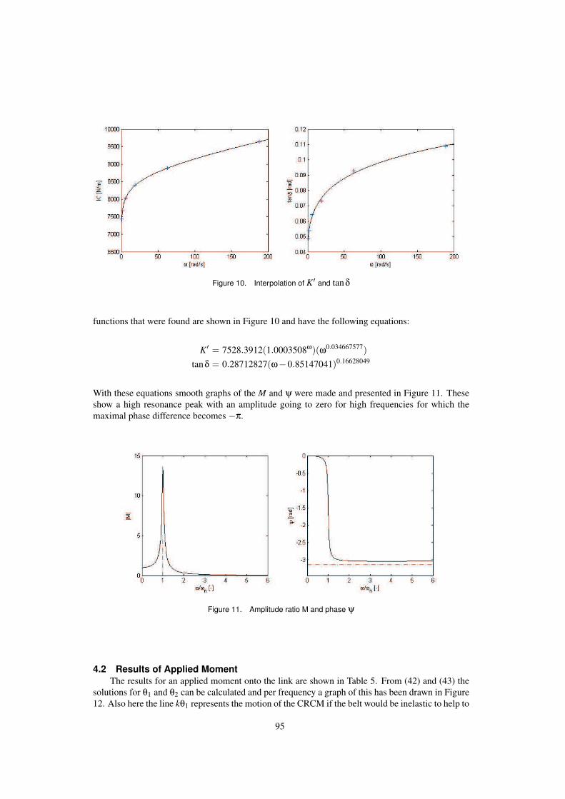
Figure 10. Interpolation of K′ and tanδ
functions that were found are shown in Figure 10 and have the following equations:
K′ = 7528.3912(1.0003508ω)(ω0.034667577)tanδ = 0.28712827(ω−0.85147041)0.16628049
With these equations smooth graphs of the M and ψ were made and presented in Figure 11. Theseshow a high resonance peak with an amplitude going to zero for high frequencies for which themaximal phase difference becomes −π.
Figure 11. Amplitude ratio M and phase ψ
4.2 Results of Applied MomentThe results for an applied moment onto the link are shown in Table 5. From (42) and (43) the
solutions for θ1 and θ2 can be calculated and per frequency a graph of this has been drawn in Figure12. Also here the line kθ1 represents the motion of the CRCM if the belt would be inelastic to help to
95

Figure 12. Solutions for θ1 and θ2
visualize the phase of the motion of the CRCM with respect to the motion of the link. The amplitudeand phase behavior is as expected equal to that of and applied excitation of the link. Figure 13 showsthe shaking moment MR calculated by (56) and the applied moment M. The reaction moment for thethree lowest frequencies is low, but exists while for the high frequencies it grows and approximatesthe applied moment.
Table 5. Results of Applied Moment
w
[Hz]
-2.7716
-0.0007
-0.0097
-0.0001
-0.1359
-0.0076
3
0.3
1
0.1
10
30
0.0066
2.0981
0.1665
19.086
0.0357
0.0018
|M |R
[Nm]|a*|
[rad]y1
[rad]
-0.0736
-0.0007
-0.0074
-0.0001
1.0016
0.4316
47.67
45.56
46.59
44.83
49.03
51.06
wn
[Hz]
-0.0135
-0.0001
-0.0012
-0.0000
-2.9055
-3.0247
0.176
14.890
1.363
133.81
0.021
0.0001
|b*|[rad]
y2
[rad]
96
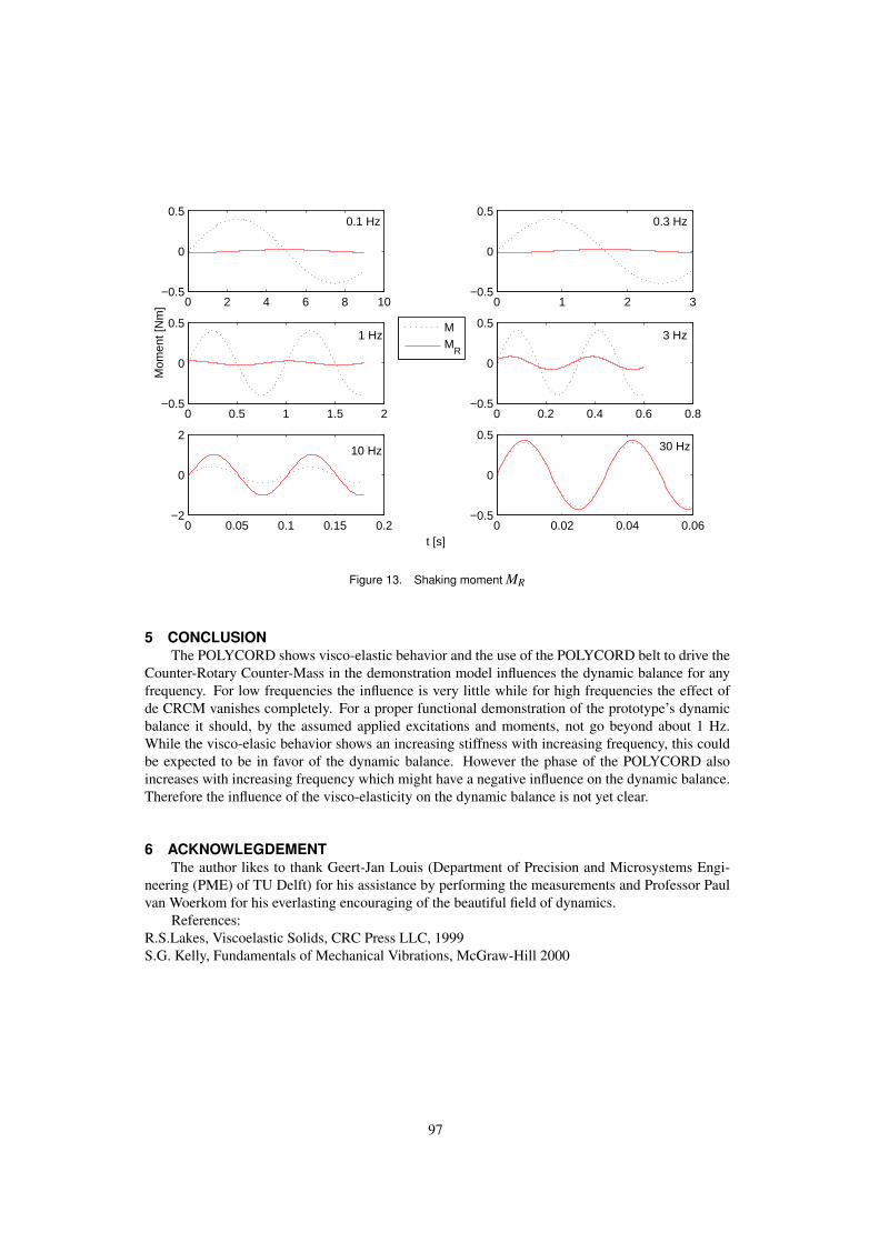
0 2 4 6 8 10−0.5
0
0.5
0 1 2 3−0.5
0
0.5
0 0.5 1 1.5 2−0.5
0
0.5
0 0.2 0.4 0.6 0.8−0.5
0
0.5
0 0.05 0.1 0.15 0.2−2
0
2
0 0.02 0.04 0.06−0.5
0
0.5
t [s]
Mom
ent [
Nm
]
MM
R
3 Hz
0.3 Hz
1 Hz
10 Hz 30 Hz
0.1 Hz
Figure 13. Shaking moment MR
5 CONCLUSIONThe POLYCORD shows visco-elastic behavior and the use of the POLYCORD belt to drive the
Counter-Rotary Counter-Mass in the demonstration model influences the dynamic balance for anyfrequency. For low frequencies the influence is very little while for high frequencies the effect ofde CRCM vanishes completely. For a proper functional demonstration of the prototype’s dynamicbalance it should, by the assumed applied excitations and moments, not go beyond about 1 Hz.While the visco-elasic behavior shows an increasing stiffness with increasing frequency, this couldbe expected to be in favor of the dynamic balance. However the phase of the POLYCORD alsoincreases with increasing frequency which might have a negative influence on the dynamic balance.Therefore the influence of the visco-elasticity on the dynamic balance is not yet clear.
6 ACKNOWLEGDEMENTThe author likes to thank Geert-Jan Louis (Department of Precision and Microsystems Engi-
neering (PME) of TU Delft) for his assistance by performing the measurements and Professor Paulvan Woerkom for his everlasting encouraging of the beautiful field of dynamics.
References:R.S.Lakes, Viscoelastic Solids, CRC Press LLC, 1999S.G. Kelly, Fundamentals of Mechanical Vibrations, McGraw-Hill 2000
97

MATLAB FILES%%%%%%%%%%%%%%%%%%%%%%%%%%%%%%%%%%%%%%%%%%%%%%%%%% Calculations of the influence of Belt %%%%%% Elasticity on the Dynamic Balance of a %%%%%% CRCM-Balancer mechanism model %%%%%% %%%%%% Volkert van der Wijk %%%%%% Dec. 2007 %%%%%%%%%%%%%%%%%%%%%%%%%%%%%%%%%%%%%%%%%%%%%%%%%%
clear allclcclose all
%%% Measured valuestandelta = [0.10874; % phase
0.092845;0.073093;0.064296;0.05386;0.048779];
w = 2*pi*[30;10;3;1;0.3;0.1]; % frequency
Ka = [9642.8; % Real part of Stiffness8888.2;8403.8;8028.3;7676.8;7431.2];
%%% ParametersS0 = 15/180*pi/2; % Applied Excitation of linkM0 = 0.4 % Applied Moment on linkr1 = 0.032 % Radi of pulleysr2 = 0.004I2 = 9.466993346619643e-004 % Inertia of CRCMI1 = (r1/r2-1)*9.466993346619643e-004; %Inertia of link (balanced)
%%%%%%%%%%%%%%%%%%%%%%%%%%%%%%%%%%%%%%%%%%%%%%%%%%%%%%%%%%%% Dynamic simulation of Applied Excitation on link %%%%%%%%%%%%%%%%%%%%%%%%%%%%%%%%%%%%%%%%%%%%%%%%%%%%%%%%%%%%
wn = sqrt((2*Ka*r2.ˆ2)/(I2)) % Eigenfrequencies
%%%Magnification factor and AngleMabs = sqrt(1+tandelta.ˆ2)./sqrt((1-(w./wn).ˆ2).ˆ2+tandelta.ˆ2)psi = atan((-tandelta.*(w./wn).ˆ2)./(1-(w./wn).ˆ2+tandelta.ˆ2))
b1 = -(r1/r2-1)*S0*Mabs % Real value of b*
%%% Solutions for Theta 2
98

for i = 1:10000t(i) = (i-1)/1000;theta1(:,i) = S0*sin(w.*t(i));theta2r(:,i)= -(r1/r2-1).*theta1(:,i);theta2(:,i) = b1.*sin(w*t(i)+psi);end
%%% Plot of Solutionsfiguresubplot(3,2,1)a = 6;n = 9001;plot(t(1:n),theta1(a,1:n),’:b’), hold onplot(t(1:n),theta2r(a,1:n),’-.k’)plot(t(1:n),theta2(a,1:n),’r’), hold offsubplot(3,2,2)a = 5;n = 3001;plot(t(1:n),theta1(a,1:n),’:b’), hold onplot(t(1:n),theta2r(a,1:n),’-.k’)plot(t(1:n),theta2(a,1:n),’r’), hold offsubplot(3,2,3)a = 4;n = 1801;plot(t(1:n),theta1(a,1:n),’:b’), hold onplot(t(1:n),theta2r(a,1:n),’-.k’)plot(t(1:n),theta2(a,1:n),’r’), hold offsubplot(3,2,4)a = 3;n = 601;plot(t(1:n),theta1(a,1:n),’:b’), hold onplot(t(1:n),theta2r(a,1:n),’-.k’)plot(t(1:n),theta2(a,1:n),’r’), hold offsubplot(3,2,5)a = 2;n = 181;plot(t(1:n),theta1(a,1:n),’:b’), hold onplot(t(1:n),theta2r(a,1:n),’-.k’)plot(t(1:n),theta2(a,1:n),’r’), hold offsubplot(3,2,6)a = 1;n = 61;plot(t(1:n),theta1(a,1:n),’:b’), hold onplot(t(1:n),theta2r(a,1:n),’-.k’)plot(t(1:n),theta2(a,1:n),’r’), hold offxlabel(’t [s]’)ylabel(’A [rad]’)
%%% Curve fitting for smooth graphs%%% Equation parameters for Ka and Tandeltaak = 7528.3912;bk = 1.0003508;
99
ck = 0.034667577;axi = 0.28712827;bxi = -0.85147041;cxi = 0.16628049;axi = 0.045710995bxi = -0.85504516cxi = 0.16614162
for j = 1:2000w2(j) = j/10;Ka2(j) = ak*(bkˆw2(j))*(w2(j)ˆck); % Hoerl Model: y=a*(bˆx)*(xˆc)tandelta2(j) = axi*(w2(j)-bxi)ˆcxi; % Shifted Power Fit: y=a*(x-b)ˆcend
wn2 = sqrt((2*Ka2*r2.ˆ2)/(I2)); % Eigenfrequencies
%%%Magnification factor and AngleMabs2 = sqrt(1+tandelta2.ˆ2)./sqrt((1-(w2./wn2).ˆ2).ˆ2+tandelta2.ˆ2);A = -tandelta2.*(w2./wn2).ˆ2;B = 1-(w2./wn2).ˆ2+tandelta2.ˆ2;psi2 = -acos(B./sqrt(A.ˆ2+B.ˆ2));
b2 = -(r1/r2-1)*S0*Mabs2; % Real value of b*
%%% plot of magnification factorsubplot(1,2,1)plot(w2(4:end)./wn2(4:end), Mabs2(4:end),’k’), hold online([1 1],[0 5]), hold offaxis([0 6 0 15])xlabel(’\omega/\omega_n [-]’)ylabel(’|M|’)
%%% plot of phasesubplot(1,2,2)plot(w2(4:end)./wn2(4:end), psi2(4:end),’k’), hold online([0 6],[-pi -pi]), hold offaxis([0 6 -1.1*pi 0])xlabel(’\omega/\omega_n [-]’)ylabel(’\psi [rad]’)
%%% plot of data interpolationfiguresubplot(1,2,1)plot(w2,Ka2,’k’),hold onplot(w,Ka,’+’),hold offxlabel(’\omega [rad/s]’)ylabel(’\K [N/m]’)subplot(1,2,2)plot(w2,tandelta2,’k’),hold onplot(w,tandelta,’+’),hold offxlabel(’\omega [rad/s]’)ylabel(’tan\delta [rad]’)
100

%%%%%%%%%%%%%%%%%%%%%%%%%%%%%%%%%%%%%%%%%%%%%%%%%%%%%%% Dynamic simulation of Applied Moment on Link %%%%%%%%%%%%%%%%%%%%%%%%%%%%%%%%%%%%%%%%%%%%%%%%%%%%%%%
%%% Eigenfrequencieswn = sqrt((2*Ka*(I1*r2ˆ2+I2*(r1-r2)ˆ2))./(I1*I2))
%%% Separating real and imaginary partsa = -w.ˆ2*I2*M0+2*r2ˆ2.*Ka*M0;b = 2*r2ˆ2.*Ka*M0.*tandelta;c = w.ˆ4*I1*I2-2*w.ˆ2.*Ka.*(I1*r2ˆ2+I2*(r1-r2).ˆ2);d = -2*w.ˆ2.*Ka.*(I1*r2ˆ2+I2*(r1-r2).ˆ2).*tandelta;
aare = (a.*c +b.*d) ./(c.ˆ2 +d.ˆ2); % Reaaim = (b.*c -a.*d) ./(c.ˆ2 +d.ˆ2); % Im
a = -2*r2*(r1-r2).*Ka*M0;b = -2*r2*(r1-r2).*Ka*M0.*tandelta;
bare = (a.*c +b.*d) ./(c.ˆ2 +d.ˆ2); % Rebaim = (b.*c -a.*d) ./(c.ˆ2 +d.ˆ2); % Im
%%% Calculation of absolut valuaes for a and b%%% and their phasesaa = aare+i*aaimaaabs = sqrt(aaim.ˆ2+aare.ˆ2)psi1 = -atan(aaim./aare)
ba = bare+i*baimbaabs = sqrt(baim.ˆ2+bare.ˆ2)psi2 = atan(baim./bare)
%%% Solutions for Theta 1 and Theta 2for i = 1:10000t(i) = (i-1)/1000;theta1(:,i) = -aaabs.*sin(w.*t(i)+psi1);theta2r(:,i)= -(r1/r2-1).*theta1(:,i);theta2(:,i) = baabs.*sin(w*t(i)+psi2);end
%%% Plot of Solutionsfiguresubplot(3,2,1)a = 6;n = 9001;plot(t(1:n),theta1(a,1:n),’:b’), hold onplot(t(1:n),theta2r(a,1:n),’-.k’)plot(t(1:n),theta2(a,1:n),’r’), hold offsubplot(3,2,2)a = 5;n = 3001;plot(t(1:n),theta1(a,1:n),’:b’), hold on
101

plot(t(1:n),theta2r(a,1:n),’-.k’)plot(t(1:n),theta2(a,1:n),’r’), hold offsubplot(3,2,3)a = 4;n = 1801;plot(t(1:n),theta1(a,1:n),’:b’), hold onplot(t(1:n),theta2r(a,1:n),’-.k’)plot(t(1:n),theta2(a,1:n),’r’), hold offsubplot(3,2,4)a = 3;n = 601;plot(t(1:n),theta1(a,1:n),’:b’), hold onplot(t(1:n),theta2r(a,1:n),’-.k’)plot(t(1:n),theta2(a,1:n),’r’), hold offsubplot(3,2,5)a = 2;n = 181;plot(t(1:n),theta1(a,1:n),’:b’), hold onplot(t(1:n),theta2r(a,1:n),’-.k’)plot(t(1:n),theta2(a,1:n),’r’), hold offsubplot(3,2,6)a = 1;n = 61;plot(t(1:n),theta1(a,1:n),’:b’), hold onplot(t(1:n),theta2r(a,1:n),’-.k’)plot(t(1:n),theta2(a,1:n),’r’), hold offxlabel(’t [s]’)ylabel(’A [rad]’)
%%% Shaking Momentq = aare;s = aaim;u = bare;v = baim;
C1 = M0-2.*Ka.*r1.*(r2.*(u-q)+r1.*q)C2 = -2.*Ka.*r1.*(r2.*(v-s)+r1.*s)MRabs = sqrt(C1.ˆ2+C2.ˆ2)phi = -atan(C2./C1)
for i = 1:10000t(i) = (i-1)/1000;MA(:,i) = M0*sin(w*t(i));MR(:,i) = MRabs.*sin(w*t(i)+phi);end
%%% plot of Shaking moment and Applied Moment on the basesubplot(3,2,1)a = 6;n = 9001;plot(t(1:n),MA(a,1:n),’:k’), hold on
102

plot(t(1:n),MR(a,1:n),’r’), hold offsubplot(3,2,2)a = 5;n = 3001;plot(t(1:n),MA(a,1:n),’:k’), hold onplot(t(1:n),MR(a,1:n),’r’), hold offsubplot(3,2,3)a = 4;n = 1801;plot(t(1:n),MA(a,1:n),’:k’), hold onplot(t(1:n),MR(a,1:n),’r’), hold offsubplot(3,2,4)a = 3;n = 601;plot(t(1:n),MA(a,1:n),’:k’), hold onplot(t(1:n),MR(a,1:n),’r’), hold offsubplot(3,2,5)a = 2;n = 181;plot(t(1:n),MA(a,1:n),’:k’), hold onplot(t(1:n),MR(a,1:n),’r’), hold offsubplot(3,2,6)a = 1;n = 61;plot(t(1:n),MA(a,1:n),’:k’), hold onplot(t(1:n),MR(a,1:n),’r’), hold offxlabel(’t [s]’)ylabel(’Moment [Nm]’)legend(’M’,’M_R’)
103

APPENDIX B-
CALCULATIONS OF THE TRANSMISSION RATIOFOR THREE CONFIGURATIONS OF A 1-DOF
ROTATABLE COUNTER-ROTARYCOUNTER-MASS BALANCED LINK
104

CALCULATIONS OF THE TRANSMISSION RATIO FORTHREE CONFIGURATIONS OF A 1-DOF ROTATABLE
COUNTER-ROTARY COUNTER-MASS BALANCED LINK
INTRODUCTIONThis section shows the calculations of the transmission ratio of three different Counter-Rotary
Counter-Mass (CRCM-) configurations. In this configuration the CRCM is driven by a belt, a pairof inner gears or a pair of outer gears by which it counter-rotates with respect to the link. This withthe purpose to dynamically balance the link. It will be shown that the equation for the transmissionratio is equal for all configurations and is dependent on the radii of the fixed gear at the origin O andthe gear at the CRCM. The equations of the transmission ratio are obtained from the kinematics ofeach configuration and treated separately; First the belt driven CRCM, then the use of outer gearsand finally the configuration with inner gears.
BELT OR CHAIN DRIVEN CRCM
m*
I*
Ok m I
l*
l
r*
r*
fg
q.
y.
Figure 1. BELT DRIVEN CRCM
r∗ and r f g are the radii of the CRCM (m∗) and the fixed gear respectively. A parallel transmis-sion will be for r∗ = r f g. This means the angular velocity of the CRCM ψ depends on the differenceof these radii and can be calculated as:
r∗ψ = (r∗f g− r∗)θ
ψ =( r∗f g
r∗−1
)θ
= −kθ
105

O
m*
I*
r*
fg
l*
lu*
q.
y.
a.
m I
a)
r*
VA
m*
I*
y.
2VBb)
r*
int
VB
2VB
a.
A
c)
AB
B
Figure 2. CRCM DRIVEN BY OUTER GEARS
CRCM DRIVEN BY OUTER GEARSFrom Fig. 2a:
VA = l∗θVB = u∗θl∗ = r∗+2r∗int + r∗f g
u∗ = r∗int + r∗f g (1)
From Fig. 2c and with Eqn. (1):
α =2VB−VB
r∗int=
VB
r∗int=
u∗
r∗intθ
=r∗int + r∗f g
r∗intθ =
( r∗f g
r∗int+1
)θ (2)
From Fig. 2b and with Eqn. (1) and (2):
ψ =2VB−VA
r∗=
2u∗− l∗
r∗θ
=2(r∗int + r∗f g)− (r∗+2r∗int + r∗f g)
r∗θ
=r∗f g− r∗
r∗θ =
( r∗f g
r∗−1
)θ
= −kθ
CRCM DRIVEN BY INNER GEARSFrom Fig. 3a:
VA = l∗θl∗ = r∗f g− r∗ (3)
106

O
r*
VA
Am
*I*
y.
2VAb)
A
l*
l
q.
y.
m I
r* r
*
fg
a)
m*
I*
Figure 3. CRCM DRIVEN BY INNER GEARS
From Fig. 3b and with Eqn. (3):
ψ =2VA−VA
r∗=
VA
r∗=
l∗
r∗θ
=r∗f g− r∗
r∗θ =
( r∗f g
r∗−1
)θ
= −kθ
CONCLUSIONFor all three CRCM-configurations the transmission ratio can be calculated with the equation:
k = 1− r∗f g
r∗(4)
in which r∗f g and r∗ are the radii of the fixed gear at O and the gear at the CRCM respectively.
107

FINE
108