towards semantically integrated models and tools for cyber
TRANSCRIPT

This is a repository copy of Towards Semantically Integrated Models and Tools for Cyber-Physical Systems Design.
White Rose Research Online URL for this paper:http://eprints.whiterose.ac.uk/106530/
Version: Accepted Version
Proceedings Paper:Larsen, Peter Gorm, Fitzgerald, John, Woodcock, Jim orcid.org/0000-0001-7955-2702 et al. (3 more authors) (2016) Towards Semantically Integrated Models and Tools for Cyber-Physical Systems Design. In: 7th International Symposium on Leveraging Applications of Formal Methods, Verification, and Validation. , pp. 171-186.
[email protected]://eprints.whiterose.ac.uk/
Reuse Unless indicated otherwise, fulltext items are protected by copyright with all rights reserved. The copyright exception in section 29 of the Copyright, Designs and Patents Act 1988 allows the making of a single copy solely for the purpose of non-commercial research or private study within the limits of fair dealing. The publisher or other rights-holder may allow further reproduction and re-use of this version - refer to the White Rose Research Online record for this item. Where records identify the publisher as the copyright holder, users can verify any specific terms of use on the publisher’s website.
Takedown If you consider content in White Rose Research Online to be in breach of UK law, please notify us by emailing [email protected] including the URL of the record and the reason for the withdrawal request.

Towards Semantically Integrated Models and Tools for
Cyber-Physical Systems Design
Peter Gorm Larsen1, John Fitzgerald2, Jim Woodcock3, Rene Nilsson1, Carl
Gamble2, and Simon Foster3
1 Department of Engineering, Aarhus University, Denmark , {pgl,rn}@eng.au.dk2 School of Computing Science, Newcastle University, UK
{john.fitzgerald,carl.gamble}@ncl.ac.uk3 Department of Computer Science, University of York,
{jim.woodcock,simon.foster}@york.ac.uk
Abstract. We describe an approach to the model-based engineering of embed-
ded and cyber-physical systems, based on the semantic integration of diverse
discipline-specific notations and tools. Using the example of a small unmanned
aerial vehicle, we explain the need for multiple notations and collaborative mod-
elling. Learning from experience with binary co-modelling based on a bespoke
operational semantics, we describe current work delivering an extended approach
that enables integration of multiple models and tools in a consistent tool chain,
founded on an extensible semantic framework exploiting the Unifying Theories
of Programming.
1 Introduction
In Cyber-Physical Systems (CPSs), computing processes interact closely with
physical systems and humans. Examples range from networked embedded sys-
tems to large-scale applications such as distributed transport systems. The ef-
fective design of dependable CPSs requires methods and tools that bring to-
gether diverse engineering disciplines. Without these it would be difficult to
gain confidence in the system-level consequences of design decisions made in
any one domain, and it would be challenging to manage trade-offs between
them. How, then, can we support such multidisciplinary design with semanti-
cally well-founded approaches?
We start from the view that disciplines such as software, mechatronic and
control engineering have evolved notations and theories that are tailored to their
needs, and that it is undesirable to suppress this diversity by enforcing uniform
general-purpose models. Our goal is to achieve a practical integration of diverse
formalisms at the semantic level, and to realise the benefits in integrated tool
chains. To the CPS engineer, the system of interest includes both computational
and physical elements, so the foundations, methods and tools of CPS engineer-
ing should incorporate both the discrete-event (DE) models of computational
processes, and the continuous-value and continuous-time (CT) formalisms of
physical engineering.
Our initial approach is to support the development of collaborative mod-
els (co-models) containing DE and CT elements expressed in diverse notations,
and to support their analysis by means of co-simulation based on a reconciled
operational semantics of the individual notations’ simulators. This enables ex-
ploration of the design space and allows relatively straightforward adoption in
businesses that are unfamiliar with formal methods. Our current work extends
this approach with co-simulation of extensible groups of semantically diverse
models, and at the same time the semantic foundations are extended using Uni-
fying Theories of Programming (UTP) to permit analysis using advanced tools.
We are not unique in proposing co-models as a solution to the problem of
modelling multi-domain systems, the HybridSim [29] tool chain, supports im-
porting existing system components from multi-domains into SysML blocks [27],
where Functional Mock-up Units (FMUs) and configuration scripts can be gen-
erated and co-simulated. CPSs are also modelled as hybrid systems, including
techniques such as hybrid statecharts [20] and hybrid automata [1], where finite
control graphs describe discrete behaviours and differential equations describe
continuous behaviours. More recently, several languages have been proposed to
describe hybrid systems and to support simulation and verification and a survey
of these is presented by Carloni et al. [6].
The challenge of providing semantic foundations for CPSs that allow the de-
velopment of comprehensive and integrated formal models is widely acknowl-
edged [4,23]. The need for rigorous modelling foundations to ensure safe CPSs
and the importance of well-founded semantic meta-models for CPSs with the
ability to model and compare heterogeneous computational models have been
identified [7], and the Ptolemy framework, with its actor-based model, proposed
as a solution. Our UTP approach similarly provides a uniform notation for com-
putational models in the hybrid relational calculus, with CyPhyCircus provid-
ing actor-style concurrency. Other semantic approaches to CPS modelling in-
clude MontiArc, which is given a denotational semantics in [16] and a semantic
agent framework for CPS.
We first introduce a small case study based on the control of a quadrotor
Unmanned Aerial Vehicle (UAV) in Section 2, demonstrating the merits of spe-
cialist notations for DE and CT modelling of system elements. Using this as a
running example, we show how a single DE model in the notation VDM-RT and
a CT model in the 20-sim tool can be successfully integrated in a co-model (Sec-
tion 3). We then describe our current work extending this approach to accom-
modate more diverse component models, and to better integrate co-modelling
in the full development toolchain (Section 4). We discuss our approach to pro-

Fig. 1. Main components of a quadrotor UAV
viding integrated semantic foundations needed to underpin such co-modelling
(Section 5) before reviewing related work and looking forward (Section 6).
2 Example: UAV Control
We consider the model of a small quadrotor UAV, which involves software,
electrical and mechanical domains [15]. The controller is implemented on an
embedded device with discrete logic, while the electronics and physical dy-
namics are described in terms of differential equations over continuous values.
We would thus expect to have a CT model of the physical dynamics and a DE
model of the control application. We use VDM-RT as the DE notation and
20-sim as the CT notation; both are described in [9]. VDM-RT is an exten-
sion of the Vienna Development Method’s modelling language with features for
object-orientation, concurrency and real-time computation, including the distri-
bution of processes to virtual CPUs [28]. 20-sim is a package for modelling and
simulating complex physical systems [21,2], which provides an abstract rep-
resentation of differential equations. Iconic diagrams with flow ports, adopted
from bond graphs, are used to describe both the electronics and mechanics of
the propulsion system, whereas rigid body dynamics are modelled directly with
differential equations.
Our UAV (Figure 1) consists of an airframe, sensors, actuators, controller
and battery. Sensors include accelerometers, gyroscopes and GPS. The actuators
are four Electronic Speed Controllers (ESCs), motors and rotors. The overall
system controller reads sensor data and steers the UAV to a desired state by
adjusting the set points of each motor. The desired state is usually given by a
pilot and retrieved through telemetry.
2.1 Modelling the Physical Components
The CT model of the UAV, Figure 2, shows the main components of the model
along with their relationships. From the diagram we can trace a loop formed by

Fig. 2. Top level of the CT model showing connections of the main model elements
Fig. 3. Part of the CT model of quadrotor UAV propulsion system
the controller → motor controllers → motors → rotors → rigid body dynamics
→ sensors → controller. The controller itself is modelled in the DE environ-
ment, so the purpose of the controller block here is to contain the declarations
defining the variables we expect the DE controller to set and also those moni-
tored variables we want to expose to the DE controller.
Following the loop round from the controller first we arrive at the motor
controllers and Figure 3 depicts expanded 20-sim models of the ESC, motor
and rotor using iconic diagrams. The ESC is represented by a controlled voltage
source and the motor is modelled as an ideal DC motor with electrical para-
sitic components, mechanical losses and inertia. This construction allows the
modeller to specify relatively simple equations for each subcomponent, such as
Ohm’s law for a resistor: U = R ∗ I. By assigning indifferent causality to all
flow ports, an explicit model is achieved, enabling the 20-sim tool to calculate
the resulting differential equations.
In cases where the dynamics are not easily described by composition of
simple components such as in the rigid body model of the UAV, differential
equations are recorded directly. For example, angular acceleration is calculated
with a differential equation, since it incorporates gyroscopic effects (Equations 1
and 2):
aang = I−1 ∗ (−vang × (I ∗ vang)) + t) (1)
vang =
∫
aang (2)

Fig. 4. Magnetometer component of the CT model
where aang and vang are angular accelerations and velocities respectively (three-
dimensional); t is the angular moments and I is the rotational inertia matrix.
These equations are easily represented in 20-sim’s textual notation as follows:
a = inverse(I)*(-cross(v,(I*v)) + t);
v = int(a);
The output from the rigid body dynamics is processed by five blocks, each
representing one of the sensor components possessed by the UAV. The function
of these blocks is to take the raw dynamic properties of the UAV body, such as
linear and rotational acceleration, velocities and positions and to process them
to give sensors outputs that are consistent with those of the real hardware sen-
sors on the UAV. The sensor models here, such as the magnetometer shown in
Figure 4, are ideal in the sense that their outputs do not contain error or exhibit
fault behaviour as described in [9].
Iconic diagrams let the engineer build a model by connecting blocks that
represent dominant physical elements; blocks contain equations representing
how those elements affect the effort and flow. This is “what we want to model”.
The above equations are not, however, suitable for simulation and 20-sim ma-
nipulates them, according to the connections between their flow ports, into a
form that can be simulated using one of the integration methods offered by the
tool. Importantly, all elements connected by power bonds are considered when
generating the new set of equations and so interactions and feedback between
components that may be on opposite corners of the model are included; so we
arrive at a set of equations that represent the “dynamic behaviour of what we
want to model”.
If the engineer were to attempt to model this system using a DE environment
such as VDM-RT then they are obliged to do two things. First, instead of being
able to think about the behaviour of individual elements, they must generate the
equations that represent the dynamic behaviour of the whole system, including
feedback, manually. This dynamic system would change each time a component

is introduced or removed from the system they are modelling. Second, the en-
gineer is obliged to construct numerical solvers that implement one or more of
the integration methods required to generate continuous results. Thus, while it
is not impossible to model such a dynamic system using a DE environment it is
much more practical to do so using a CT tool. The iconic diagrams help manage
the complexity of generating suitable dynamic models by allowing the engineer
to only have to think about the dominant elements and their connections.
2.2 Modelling the Controller
The control application on a quadrotor UAV has two major objectives: first it
must keep the UAV stable in the air and second it must react to pilot input. Fig-
ure 5 shows a block diagram of the control application model. Here the control
loop from figure 2 is completed with the DE blocks sensor data processing →control architecture → motor control. Sensor fusion and filtering are performed
on the input data from the sensors to obtain accurate estimates of angular and
translational acceleration, velocity and position. These estimates are used in the
control architecture along with processed pilot inputs to calculate control sig-
nals for the motor control block. These control signals are expressions of angu-
lar accelerations and total thrust, which decouples the control architecture from
the motor/rotor configuration. A UAV can have from 3 to 16 rotors and, with
proper transformations in the motor control block, the control architecture can
be reused for any number of rotors.
The control architecture block is shown inside a small class diagram, includ-
ing flight modes and position and attitude controllers. The flight modes are used
with a strategy design pattern, such that the pilot is able to change flight mode
in-flight. Each of the flight mode implementations may use both the position
and an attitude controller. The position controller is based on Proportional In-
tegral Derivative (PID) control, whereas two alternative attitude controllers are
Fig. 5. High level block diagram of the control application model

modelled (and subsequently implemented): a PID-based and a Model Predictive
Control (MPC) [5] based controller. With the use of inheritance the two con-
trollers are made interchangeable, enabling comparison through co-simulations
by comparing the overall system performance.
Figure 6 shows a code snippet, from the position controller, with a type
declaration and an operation, which calculates the bearing between two vector
positions. This illustrates the use of type invariants and operation pre-conditions
in VDM. A type invariant is a condition that must be true for all instances
of that particular type throughout the entire model execution, whereas a pre-
condition needs only to be true when the given operation is called. Similarly
post-conditions can be added to operations to further improve the documenta-
tion of the precise properties of the model. If either an invariant or a pre- or
post-condition is violated a runtime error is thrown, enabling the developer to
correct the faulty behaviour of the model.
Fig. 6. Pre condition and type invariant in VDM-RT
One of the advantages of using VDM-RT with the Overture tool compared
to other formal modelling tools is the support for calling external Java and na-
tive C++ libraries. This is exploited in the modelling of the MPC controller,
where an external C++ optimisation library is used. This library is also used in
the realisation code, which is deployed to the real UAV. An increase in model
fidelity is thereby achieved. VDM-RT’s built-in notion of time makes it easy to
create a soft real-time scheduling mechanism. In the control application model
the main control loop and sensor readings are scheduled. Sensor readings are
scheduled based on the availability of data from the different types of sensor.
Figure 7 shows the controller model being deployed onto a user defined CPU,
this allows the execution time of each instruction to be simulated. The main
control loop is run at 400 Hz for the PID-based attitude control, while the MPC
controller could only be run at 100 Hz in the realisation, as it requires far more
computation.

Fig. 7. Defining CPU and deploying a controller model in VDM-RT
The DE model architecture is presented here using SysML4, reflecting the
object-oriented class structure of the VDM-RT model. This structure also lends
itself to the generation of product source code. Apart from the structure, there
are several reasons why constructing the controller in DE is preferable to a CT
model. 20-sim does support the definition of code blocks with models, there are
no language differences between these block and the normal equation blocks,
the only different being that the statements are not reordered to improve sim-
ulation speed, and so the order of equation execution and branching statement
evaluation is explicit. This permits the definition of “simple” controllers, but
there are limitations that make more complex controllers challenging.
The argument for a DE model of a controller mirrors that for using a CT
formalism to model the physics. The UAV operating modes are described in
VDM-RT using a modal controller pattern [14], and standard inheritance al-
lows the alternate PID and MPC motor controller implementations to be easily
described. Both are much more complex in 20-sim, which lacks explicit support
for these features. Similarly, VDM-RT’s support for rich data structures such as
mappings, sets and sequences allows the description of more sophisticated con-
trol than the CT formalism of 20-sim with its basic boolean, numeric and matrix
data types. The CT formalism lacks a method or function call concept, requiring
calculations at the call point, increasing the cognitive workload in understand-
ing and maintaining the controller. Finally, the explicit time budget for each
instruction in the DE model allows us to offer evidence regarding the real-time
performance of the controller.
3 Binary Co-modelling and Co-Simulation: the Crescendo Tool
In this section we describe co-modelling and co-simulation in which DE models
are developed in VDM-RT supported by the Overture/VDM simulator [22] and
CT models are developed in the 20-sim tool [21].
4 Figure 5 is not a well-formed SysML block diagram: we have condensed the presentation for
reasons of space.
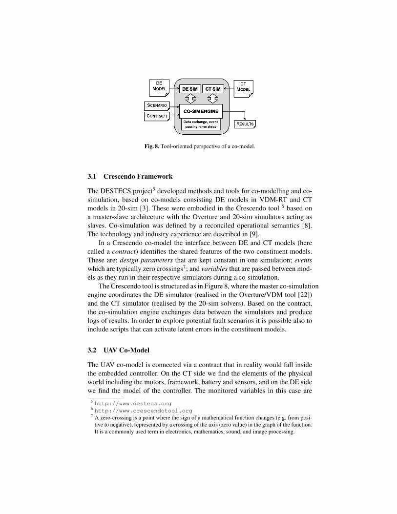
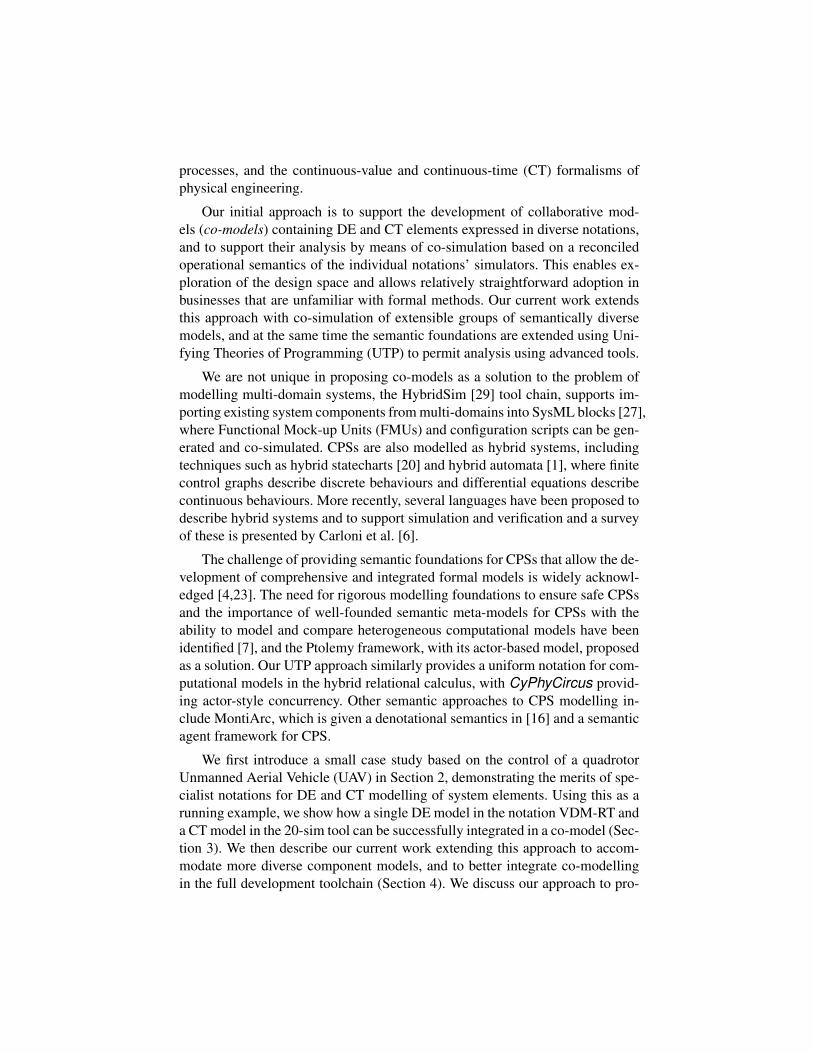
Fig. 8. Tool-oriented perspective of a co-model.
3.1 Crescendo Framework
The DESTECS project5 developed methods and tools for co-modelling and co-
simulation, based on co-models consisting DE models in VDM-RT and CT
models in 20-sim [3]. These were embodied in the Crescendo tool 6 based on
a master-slave architecture with the Overture and 20-sim simulators acting as
slaves. Co-simulation was defined by a reconciled operational semantics [8].
The technology and industry experience are described in [9].
In a Crescendo co-model the interface between DE and CT models (here
called a contract) identifies the shared features of the two constituent models.
These are: design parameters that are kept constant in one simulation; events
which are typically zero crossings7; and variables that are passed between mod-
els as they run in their respective simulators during a co-simulation.
The Crescendo tool is structured as in Figure 8, where the master co-simulation
engine coordinates the DE simulator (realised in the Overture/VDM tool [22])
and the CT simulator (realised by the 20-sim solvers). Based on the contract,
the co-simulation engine exchanges data between the simulators and produce
logs of results. In order to explore potential fault scenarios it is possible also to
include scripts that can activate latent errors in the constituent models.
3.2 UAV Co-Model
The UAV co-model is connected via a contract that in reality would fall inside
the embedded controller. On the CT side we find the elements of the physical
world including the motors, framework, battery and sensors, and on the DE side
we find the model of the controller. The monitored variables in this case are
5 http://www.destecs.org6 http://www.crescendotool.org7 A zero-crossing is a point where the sign of a mathematical function changes (e.g. from posi-
tive to negative), represented by a crossing of the axis (zero value) in the graph of the function.
It is a commonly used term in electronics, mathematics, sound, and image processing.

the outputs of the sensor devices (gyroscopes, accelerometers and GPS) and the
controlled variables are the set points for each motor. The contract and models
abstract the details of how physical sensors compute their values and also how
the ESC senses motor motion and controls the power it feeds to them.
Model-based design will be ineffective if model and realisation behaviour
do not align; effort is therefore directed into achieving a known level of model
fidelity. For example, by comparing co-simulations and real-time test, an aver-
age deviation of 2 degrees has been achieved for the attitude angles; in practice
dynamic response is at least as important as such static measures. Crescendo’s
scripting feature allows emulation of predefined user input. Figure 9 shows both
the co-simulated and measured (test) response of the UAV to scripted reference
angle changes.
time [s]
0 5 10 15 20 25 30 35 40 45
Roll
[rad]
-1
-0.5
0
0.5
1
Reference
MPC co-sim
MPC test
Fig. 9. Graph comparing of the modelled and actual roll response of the UAV to a reference input.
3.3 Evaluation of Crescendo
Crescendo has been successfully used to model embedded systems ranging from
line following robots through to dredging excavators, and demonstrable gains in
development effort have been seen through a reduction in the number of physical
prototypes needed to converge to a final design [9]. However, this co-simulation
technology is deficient in two significant areas. First, it only supports bipar-
tite co-models using a single DE model in VDM-RT and a single CT model in
20-sim. The semantic foundations are limited to an operational semantics de-
veloped for these two formalisms, and so there is significant effort in modelling
larger and more complex CPSs that may have a greater variety of constituent
models. Second, it stands alone in a development process and assumes the engi-
neer both understands what they wish to model before starting, and has external

means to analyse the results of simulation. These concerns formed the basis for
developing an integrated tool chain in the ongoing INTO-CPS project8.
4 N-ary Multi-modelling: the INTO-CPS Tool Chain
In order to address the limitations of the binary co-modelling approach based on
bespoke operational semantics, as embodied in Crescendo, we are developing a
more open integrated tool chain to allow n-ary co-simulation of a wider range
of model types. In order to facilitate this, we develop an extensible semantic
foundation using UTP. Figure 10 gives a graphic overview of the toolchain,
which is being developed in INTO-CPS.
In the INTO-CPS tool chain, requirements and CPS architectures may be
expressed using SysML. We define an architectural profile that allows cyber
and physical system elements to be identified such that each of these elements
corresponds to a constituent model. From each element, we generate an interface
following the Functional Mockup Interface (FMI) standard9. In our approach,
which is inspired by HybridSim, the tools in which the constituent models are
developed can then import these interfaces and export conformant executable
Functional Mockup Units (FMUs).
Heterogeneous system models can be built around the FMI interfaces, per-
mitting these heterogeneous multi-models to be co-simulated, and to allow static
analysis, including model checking (of appropriate abstractions). A Co-simulation
Orchestration Engine (COE) manages the co-simulation of multi-models and is
built by combining existing co-simulation solutions. The COE permits hardware-
in-the-loop and software-in-the-loop analysis. Results of multiple co-simulations
can be collated, permitting systematic design space exploration, and allowing
test automation based on test cases generated from the SysML requirement dia-
grams [25].
To date, the CPS SysML profile has been demonstrated in Modelio10. FMI-
conformant constituent models have been produced from VDM-RT, and the CT
formalisms 20-sim and OpenModelica [13]11.
Returning to the UAV case study, the INTO-CPS tool chain will support
multiple improvements over the Crescendo version of the model. The first of
these is the support for more than two FMUs in a single co-model. This greatly
reduces the workload when constructing a model of a swarm of identical UAVs
as it is possible to create multiple instances of the UAV controller and physics
8 http://http://into-cps.au.dk/9 FMI essentially defines a standardised interface to be used in computer simulations to develop
complex CPSs.10 http://www.modelio.org/11 https://www.openmodelica.org/

Fig. 10. The current INTO-CPS Tool Chain
models. The resulting swarm of UAVs then interact via one or more FMUs rep-
resenting communications and the physical world. The second benefit is that
FMUs can be created using any tool that exports a compatible FMU and so
could allow the generation of a terrain model from a mapping tool. The final
benefit is the possibility to use third party or proprietary FMUs as part of the
simulation, in an industrial context this would allow competing organisations to
share models to develop the UAV swarm without revealing sensitive details of,
for example, how their controller performs key tasks such as route finding.
5 A Unified Semantic Approach
We are developing unified foundations for the INTO-CPS languages using a
framework called Unifying Theories of Programming (UTP) [19], that supports
the description and unification of formal semantics for heterogeneous modelling
languages. The core notation of the UTP is the alphabetised predicate calculus,
that consists of the usual operators of a first-order logic, ranging over the vari-
ables of a particular model. UTP is then based around the idea that any program
or model can be represented by such a predicate. For example, the operators of
an imperative program can be denoted by dividing the alphabet α(P) of a pred-
icate P into input variables x and output variables x′. Imperative programming
operators can then be given predicative interpretations, for example assignment
x := v can be formally denoted by predicate x′ = v ∧ y′ = y where y represents
all other variables in the alphabet.
Unification of semantic models is achieved through isolation of “UTP theo-
ries” that describe the foundational paradigms, such as real-time, object orienta-
tion, or concurrency, and thus act as semantic “building blocks” [10]. Describing
various language semantics in terms of these building blocks, also allows one to
link them through the common theoretical factors. For example, we could link

P,Q ::= P ; Q | P 2 B 3 Q | x := e | P∗
| Pω | 〈 x = f (t, x) |B 〉 | P [B ]Q | ⌈⌈P⌉⌉
Table 1. Signature of hybrid relational calculus
theories of discrete and continuous real-time through an appropriate discretisa-
tion. Combination of several UTP theories then allows production of denota-
tional semantics for a particular language. Then we can derive other semantic
models, such as operational or algebraic semantics, which can be used as input
for the development of tools. This will then ensure the well-foundedness of the
INTO-CPS tool-chain, by allowing the evidence of several tools to be soundly
composed. Our overall approach to semantics in INTO-CPS is thus to develop
UTP theories that will provide the semantic building blocks, and then use these
to produce formal semantic models. UTP theories are characterised by observa-
tional variables and healthiness conditions, the latter of which act as invariants
on the structure of the theory. For example we have observational variables ti
and ti′ that represent the start and end time of a model’s behaviour. A healthiness
condition of such a theory is that time should proceed in a forward direction, that
is ti ≤ ti′. Healthiness conditions are usually characterised as idempotent and
monotone functions, such that their images form a lattice.
CPSs are usually represented by hybrid computational models consisting of
both discrete and continuous variables, and thus we first develop a UTP theory
of hybrid relations [11]. In addition to discrete input and output variables this
theory also provides support for continuous variable trajectories x : R → R. The
healthiness condition for this theory is called HCT : it ensures that variables are
piecewise continuous over a particular interval of time. The signature of the
theory is shown in Table 1. It includes the standard operators of the relational
calculus like sequential composition P ; Q, if-then-else conditional P 2 b 3 Q,
assignment x := v, finite iteration P∗
, and infinite iteration Pω. Additionally it
has three operators for continuous modelling. 〈Fn |B 〉 allows the behaviour of
a continuous variables to be described by a system of differential and algebraic
equations. P [B ]Q represents the evolution of a continuous system P which is
preempted when condition B is satisfied by the continuous variable valuations,
following which Q is activated. Finally, ⌈⌈P⌉⌉ is adapted from Duration Calcu-
lus [33], and states that the predicate P holds continuously over the present time
interval. The final operator can be used to logically specify the behaviour of a
continuous system. We exemplify the calculus with a simple example based on
the classic bouncing ball.
h, v := 2, 0 ;(⟨
h = v; v = −9.81⟩
[ h < 0 ] v := −v′ · 0.8))
ω
The height and velocity, h and v, are initially set to 2 and 0 respectively and
the evolution of the differential equations begin. When the condition h < 0becomes true, then the evolution is preempted and an assignment is executed
that reverses the velocity and applies a dampening factor. Finally the whole

system iterates. We have used our hybrid relational calculus to give a semantics
to a subset of Modelica, which elaborates the latter’s event handling system [11].
Moreover we have mechanised the calculus in our Isabelle based theorem prover
for UTP [12], which enables automated proof about hybrid relations.
Ultimately we will use this hybrid relational calculus to produce a formal
language into which the various notations used on this project can be soundly
converted, and appropriate analysis performed. This will then allow the integra-
tion of the heterogeneous models and a formal description of their co-simulation
in FMI. Real-time, concurrency, and rich-state modelling have already been
given substantial study in the UTP within the context of the Circus language
family [24]. Circus is a formal modelling language that combines the con-
structs of the CSP process specification language [18] for modelling concur-
rent systems with rich-state as provided by the Z notation [32]. Circus has
been extended to enable specification of discrete real-time systems by adding
constructs for modelling waiting states, timeouts, and deadlines in languages
CircusTime [30] and CML [31].
Fig. 11. INTO-CPS foundations through CyPhyCircus
The semantic model of CML will be applied to give a semantics to the real-
time CPUs and threads of VDM-RT. We will model each thread, object, CPU,
and bus from VDM-RT as different types of Circus processes. A thread, for
example, will have a collection of local state variables to be synchronised with
the corresponding object process variable store, by the CPU process, when suf-
ficient time has passed. However, the existing variants of Circus provide only
discrete time modelling, and so for INTO-CPS we are creating a further exten-
sion of Circus to enable modelling of CPSs in a language called CyPhyCircus
based on our hybrid relational calculus. This will enable the description of con-
current interacting systems, as in FMI. Moreover, we will allow the modelling

of the real-time language aspects by taking direction from Timed CSP [26], and
the system dynamics aspects from Hybrid CSP [17].
Figure 11 illustrates the approach, whereby models described in VDM-RT,
Modelica, and 20-sim can be soundly mapped to CyPhyCircus processes that
represent the individual FMUs. The composition of these different models, as
described by FMI, is given a semantics in terms of CSP processes that provide
channels to represent stepping forward and otherwise manipulating an FMU.
In addition to enabling their sound unification, the use of CyPhyCircus as a
lingua franca also enables application of various verification technologies, such
as Isabelle for theorem proving.
6 Conclusions
We have presented an argument for formal model-based CPS engineering to
allow the use of diverse notations, unifying them at a semantic level. The DE
and CT environments have appropriate abstractions for modelling software and
physical systems respectively that allow the engineer to think about what they
want to model more than what form it needs for simulation. We have also shown
that such a co-model can produce a result that is close to the response of the
physical device. Semantic integration of diverse notations has been shown to
be beneficial even for binary co-modelling with only an operational semantics
for co-simulation. However, we have identified the need to scale to n-ary multi-
models, and to provide the corresponding extensible semantic framework. We
have shown how these features may be delivered through the use of FMI-based
co-simulation in an integrated tool chain, and through the use of UTP as a vehi-
cle for supporting theory development, enabling a range of analytic tools.
We also observe that while semantically sound co-modelling is vital for the
development of dependable CPSs, it is certainly not enough on its own. There
is a need for integrated development methods and tools that span from require-
ments through to the analysis of simulation results and the generation of soft-
ware source code and test automation. Critically in this complex multi-model
environment, there is a need for efficiently managing the traceability of design
artefacts, both for the change impact analysis and for the managing of the evi-
dence on which the dependability cases for CPSs will rely.
Acknowledgments. Crescendo and Symphony were developed in DESTECS
(FP7, 248134), and COMPASS (FP7, 287829). Our current work is partially
supported by the INTO-CPS project (Horizon 2020, 664047). We would like to
thank all the participants of those projects for their efforts making this a reality.

References
1. Alur, R., Courcoubetis, C., Halbwachs, N., Henzinger, T.A., Ho, P.H., Nicollin, X., Oliv-
ero, A., Sifakis, J., Yovine, S.: The Algorithmic Analysis of Hybrid Systems. Theoretical
Computer Science 138, 3–34 (1995)
2. van Amerongen, J.: Dynamical Systems for Creative Technology. Controllab Products, En-
schede, Netherlands (2010)
3. Broenink, J.F., Larsen, P.G., Verhoef, M., Kleijn, C., Jovanovic, D., Pierce, K., Wouters, F.:
Design Support and Tooling for Dependable Embedded Control Software. In: Proceedings
of Serene 2010 International Workshop on Software Engineering for Resilient Systems. pp.
77–82. ACM (April 2010)
4. Broy, M., Cengarle, M.V., Geisberger, E.: Cyber-Physical Systems: Imminent Challenges.
In: Calinescu, R., Garlan, D. (eds.) Large-Scale Complex IT Systems. Development, Oper-
ation and Management, Lecture Notes in Computer Science, vol. 7539, pp. 1–28. Springer
Berlin Heidelberg (2012)
5. Camacho, E.F., Alba, C.B.: Model Predictive Control. Advanced Textbooks in Control and
Signal Processing, Springer-Verlag London (2007)
6. Carloni, L.P., Passerone, R., Pinto, A., Sangiovanni-Vincentelli, A.L.: Languages and Tools
for Hybrid Systems Design. Foundations and Trends in Electronic Design Automation 1(1/2)
(2006)
7. Derler, P., Lee, E.A., Sangiovanni-Vincentelli, A.: Modeling Cyber-Physical Systems. Pro-
ceedings of the IEEE (special issue on CPS) 100(1), 13 – 28 (January 2012)
8. Fitzgerald, J., Larsen, P.G., Pierce, K., Verhoef, M.: A Formal Approach to Collaborative
Modelling and Co-simulation for Embedded Systems. Mathematical Structures in Computer
Science 23(4), 726–750 (2013)
9. Fitzgerald, J., Larsen, P.G., Verhoef, M. (eds.): Collaborative Design for Embedded Systems
– Co-modelling and Co-simulation. Springer (2014)
10. Foster, S., Miyazawa, A., Woodcock, J., Cavalcanti, A., Fitzgerald, J., Larsen, P.: An ap-
proach for managing semantic heterogeneity in systems of systems engineering. In: Proc.
9th Intl. Conf. on Systems of Systems Engineering. IEEE (2014)
11. Foster, S., Thiele, B., Cavalcanti, A., Woodcock, J.: Towards a UTP semantics for Modelica.
In: 6th Intl. Symposium on Unifying Theories of Programming (2016)
12. Foster, S., Zeyda, F., Woodcock, J.: Isabelle/UTP: A mechanised theory engineering frame-
work. In: Proc. 5th Intl. Symp. on Unifying Theories of Programming. LNCS, vol. 8963, pp.
21–41. Springer (2014)
13. Fritzson, P.: Principles of Object-Oriented Modeling and Simulation with Modelica 2.1.
Wiley-IEEE Press (January 2004)
14. Gamble, C., Pierce, K.: Design patterns for use in co-modelling. In: Fitzgerald, J., Larsen,
P.G., Verhoef, M. (eds.) Collaborative Design for Embedded Systems, pp. 319–356. Springer
Berlin Heidelberg (2014)
15. Grujic, I., Nilsson, R.: Model-based development and evaluation of control for complex
multi-domain systems: Attitude control for a quadrotor uav. Tech. Rep. 23, Department of
Engineering, Aarhus University (January 2016)
16. Haber, A., Ringert, J.O., Rumpe, B.: MontiArc - Architectural Modeling of Interactive Dis-
tributed and Cyber-Physical Systems. Tech. Rep. AIB-2012-03, RWTH Aachen (Feb 2012)
17. He, J.: From CSP to hybrid systems. In: Roscoe, A.W. (ed.) A classical mind: essays in
honour of C. A. R. Hoare, pp. 171–189. Prentice Hall (1994)
18. Hoare, T.: Communication Sequential Processes. Prentice-Hall International, Englewood
Cliffs, New Jersey 07632 (1985)
19. Hoare, T., Jifeng, H.: Unifying Theories of Programming. Prentice Hall (April 1998)

20. Kesten, Y., Pnueli, A.: Timed and hybrid statecharts and their textual representation. In:
Vytopil, J. (ed.) Formal Techniques in Real-Time and Fault-Tolerant Systems, Second Inter-
national Symposium, Nijmegen, The Netherlands, January 8–10, 1992, Proceedings. Lecture
Notes in Computer Science, vol. 571, pp. 591–620. Springer (1992)
21. Kleijn, C.: Modelling and Simulation of Fluid Power Systems with 20-sim. Intl. Journal of
Fluid Power 7(3) (November 2006)
22. Larsen, P.G., Battle, N., Ferreira, M., Fitzgerald, J., Lausdahl, K., Verhoef, M.: The Overture
Initiative – Integrating Tools for VDM. SIGSOFT Softw. Eng. Notes 35(1), 1–6 (January
2010), http://doi.acm.org/10.1145/1668862.1668864
23. Lee, E.A.: Computing needs time. Communications of the ACM 52(5), 70–79 (May 2009)
24. Oliveira, M., Cavalcanti, A., Woodcock, J.: A UTP semantics for Circus. Formal Aspects of
Computing 21, 3–32 (February 2009)
25. Peleska, J.: Industrial-Strength Model-Based Testing - State of the Art and Current Chal-
lenges. Electronic Proceedings in Theoretical Computer Science abs/1303.1006, 3–28
(2013)
26. Reed, G., Roscoe, A., et al.: Timed CSP: Theory and Practice. In: REX Workshop - Real
Time: Theory and Practice, LNCS. Springer-Verlag (1992)
27. OMG Systems Modeling Language (OMG SysMLTM). Tech. Rep. Version 1.4, Object Man-
agement Group (September 2015), http://www.omg.org/spec/SysML/1.4/
28. Verhoef, M., Larsen, P.G., Hooman, J.: Modeling and Validating Distributed Embedded
Real-Time Systems with VDM++. In: Misra, J., Nipkow, T., Sekerinski, E. (eds.) FM 2006:
Formal Methods. pp. 147–162. Lecture Notes in Computer Science 4085, Springer-Verlag
(2006)
29. Wang, B., Baras, J.S.: HybridSim: A Modeling and Co-simulation Toolchain for Cyber-
physical Systems. In: 17th IEEE/ACM International Symposium on Distributed Simulation
and Real Time Applications, DS-RT 2013, Delft, The Netherlands, October 30–November
1, 2013. pp. 33–40. IEEE Computer Society (2013)
30. Wei, K., Woodcock, J., Cavalcanti, A.: Circus Time with Reactive Designs. In: Unifying
Theories of Programming. LNCS, vol. 7681, pp. 68–87. Springer (2013)
31. Woodcock, J.: Engineering UToPiA - Formal Semantics for CML. In: Jones, C., Pihlajasaari,
P., Sun, J. (eds.) FM 2014: Formal Methods. Lecture Notes in Computer Science, vol. 8442,
pp. 22–41. Springer (2014)
32. Woodcock, J., Davies, J.: Using Z – Specification, Refinement, and Proof. Prentice Hall
International Series in Computer Science (1996)
33. Zhou, C., Hoare, C.A.R., Ravn, A.P.: A calculus of durations. Information Processing Letters
40(5), 269–276 (1991)