towards virtual appliances in the future digital home · towards virtual appliances in the future...
TRANSCRIPT

Towards virtual appliances in the future digital home
David Bull
Towards virtual appliances in the future digital home
CC301 – Final Year Project Report
Author: David Bull Supervisor: Vic Callaghan

Towards virtual appliances in the future digital home
David Bull Page 2 of 117
I. Abstract Virtual Appliances is the de-composition and re-composition of modern-day appliances
in exciting new user-lead ways. The goal is to extend the functionality of existing
appliances and even build new ‘virtual’ appliances from a set of distributed services.
UPnP is at the core of this vision, providing automatic service discovery on ah-hoc
networks. XML, XSL and Apache Cocoon are used together to provide a web-based user
interface onto the Virtual Appliances. This interface is automatically tailored to the
display capabilities of client.
This project aims to demonstrate the concept of Virtual Appliances and lay the
technological groundwork. To do this a number of de-composed UPnP devices have
been created along with an adaptive user interface.
II. Acknowledgements I would like to thank the following people for their help with this project:
Dr. Vic Callaghan, project supervisor, University of Essex, for general guidance
throughout the project.
Paul Benyon, BT Exact, for feedback on the system.
Rowan Limb, BT Exact, for feedback on the system.

Towards virtual appliances in the future digital home
David Bull Page 3 of 117
III. Code Authorship All program code for this project has been self-authored and is my own work except for
parts listed below:
Please note that the code used to generate the UUIDs for the UPnP devices in this
project has been based on code from the freely available and open-source Java UUID
Generator project: http://www.doomdark.org/doomdark/proj/jug/.
Please note that the code used to access the mDorm’s sensors and effectors is based
on code available on the University of Essex CC464 module area at:
http://cscourse.essex.ac.uk/course/cc464/courseware/mDorm/.
Please note that the images and icons used by the UPnP devices in this project were
found through Google Images and are referenced in Section 10.1.1.
This project report is in accordance with Examination Regulations 6.12 and 6.13.
IV. Acronyms TINI – Tiny InterNet Interface SNAP – Simple Network Application Platform J2ME – Java 2 Micro Edition CLDC – Connected Limited Device Configuration ARP – Address Resolution Protocol mDNS-SD – multicast DNS-Service Discovery UPnP – Universal Plug and Play SSDP – Simple Service Discovery Protocol HTTPMU – HTTP Multicast over UDP HTTPU – HTTP Unicast over UDP SOAP – Simple Object Access Protocol GENA – General Event Notification Architecture XML – eXtensible Markup Language SAX – Simple API for XML XSL – eXtensible Stylesheet Language XSLT – eXtensible Stylesheet Language Transformations UUID – Universally Unique IDentifier (128-bit number) XHTML – eXtensible HyperText Markup Language

Towards virtual appliances in the future digital home
David Bull Page 4 of 117
V. Table of Contents 1. INTRODUCTION ......................................................................................6
1.1. OVERVIEW................................................................................................. 6 1.2. SCENARIO ................................................................................................. 7 1.3. PROJECT GOALS........................................................................................... 8
2. BACKGROUND.........................................................................................9
2.1. PERVASIVE AND DISTRIBUTED COMPUTING ............................................................. 9 2.2. SIMILAR PROJECTS...................................................................................... 10
2.2.1. iDorm (University of Essex)................................................................ 11 2.2.2. AutoHAN (University of Cambridge) ..................................................... 12 2.2.3. IBM’s Meta Pad & Antelope Technologies’ Modular Computing Platform ...... 13
2.3. CONCLUSION ............................................................................................ 14
3. REQUIREMENTS .................................................................................... 15
3.1. FUNCTIONAL REQUIREMENTS ........................................................................... 15 3.2. NON-FUNCTIONAL REQUIREMENTS .................................................................... 15
4. TECHNICAL DISCUSSION....................................................................... 16
4.1. HARDWARE PLATFORM .................................................................................. 16 4.1.1. TINI Board ...................................................................................... 16 4.1.2. SNAP Board..................................................................................... 18 4.1.3. PC/104 ........................................................................................... 19 4.1.4. Mini-ITX.......................................................................................... 20 4.1.5. Conclusion ...................................................................................... 21
4.2. SERVICE DISCOVERY PROTOCOLS...................................................................... 22 4.2.1. Rendezvous..................................................................................... 22 4.2.2. UPnP .............................................................................................. 24 4.2.3. Salutation ....................................................................................... 28 4.2.4. Jini................................................................................................. 30 4.2.5. Conclusion ...................................................................................... 32
5. DESIGN ................................................................................................ 33
5.1. DEVICES ................................................................................................. 33 5.2. USER INTERFACE ........................................................................................ 33 5.3. DEVICE MANAGEMENT APPLICATION................................................................... 34 5.4. RULES.................................................................................................... 35 5.5. SYSTEM ARCHITECTURE ................................................................................ 36
6. IMPLEMENTATION ................................................................................ 37
6.1. INTRODUCTION .......................................................................................... 37 6.2. DEVICES ................................................................................................. 37
6.2.1. Light Bulb ....................................................................................... 37 6.2.2. Switch ............................................................................................ 39 6.2.3. Timer ............................................................................................. 41 6.2.4 Motion Sensor ................................................................................. 44 6.2.5. Camera........................................................................................... 46 6.2.6. mDorm – Temperature and Light Sensor .............................................. 48 6.2.7. Internet Radio.................................................................................. 52 6.2.8. Audio/Video Playback Device .............................................................. 58
6.3. DEVICE IDS ............................................................................................. 61 6.4. DEVICE IDENTIFICATION & ASSOCIATION............................................................. 62
6.4.1. Identification Service ........................................................................ 62 6.4.2. Association Service ........................................................................... 63 6.4.3. Rule Proxy Device............................................................................. 66
6.5. MANAGEMENT SERVLET ................................................................................. 68 6.6. USER INTERFACE ........................................................................................ 70 6.7. UPNP & SNAP ISSUES................................................................................ 71

Towards virtual appliances in the future digital home
David Bull Page 5 of 117
6.7.1. UPnP Reliability ................................................................................ 71 6.7.2. SNAP Reliability................................................................................ 71
7. PROJECT MANAGEMENT ........................................................................ 72
7.1. WORK PLAN ............................................................................................. 72 7.2. METHODOLOGY .......................................................................................... 73 7.3. PROJECT DIARY ......................................................................................... 73 7.4. EVALUATION OF PROJECT MANAGEMENT............................................................... 76
8. TESTING & EVALUATION ....................................................................... 77
8.1. TESTING ................................................................................................. 77 8.1.1. Introduction .................................................................................... 77 8.1.2. Component Testing........................................................................... 77 8.1.3. Integration Testing & User Feedback.................................................... 77
8.2. EVALUATION............................................................................................. 78 8.2.1. User Feedback ................................................................................. 79
9. CONCLUSION........................................................................................ 81
9.1. SUMMARY OF MAIN ACHIEVEMENTS.................................................................... 81 9.2. EXTENSIONS AND FURTHER WORK..................................................................... 82 9.3. THE FUTURE…........................................................................................... 83
10. REFERENCES & BIBLIOGRAPHY ............................................................. 84
10.1. REFERENCES.......................................................................................... 84 10.1.1. Images and Icons.......................................................................... 87
10.2. BIBLIOGRAPHY........................................................................................ 87
APPENDICES ............................................................................................... 88
APPENDIX A. XML DOCUMENTS FOR THE MANAGEMENT APPLICATION ................................. 89 APPENDIX B. XSL DOCUMENTS FOR USER INTERFACE .................................................. 91 APPENDIX C. SCREENSHOTS OF THE USER INTERFACE................................................... 94 APPENDIX D. MODIFIED MDORM JAVA CLASS ............................................................ 99 APPENDIX E. TEST RESULTS..............................................................................103 APPENDIX F. GANTT CHARTS.............................................................................115 APPENDIX G. SOURCE CODE AND DOCUMENTATION ....................................................117

Towards virtual appliances in the future digital home
David Bull Page 6 of 117
1. Introduction
1.1. Overview Pervasive computing is appearing all around us and in the homes of the future
computers will be ubiquitous. Everything from the oven to the window blinds will be
augmented with microprocessors, the sole purpose of which to improve our quality of
life. There are a number of research projects currently being undertaken at various
universities and companies both in the UK and abroad trying the solve the problem of
how to make people’s lives easier through pervasive and distributed computing. This
project aims to look at the creation of virtual appliances in the future digital home.
In today’s world you can go out and buy appliances for your home such as video
recorders, hi-fi’s, dishwashers, washing machines, burglar alarms, etc. However these
devices are standalone, they can only do the job they were designed to do and they
cannot communicate with other devices. Now imagine if each of these appliances were
decomposed into their separate core functions. If each of these core functions were
then exposed and made available as network services, other devices would then be
able to communicate with each other and work together.
This is a completely new and novel idea as there is nothing else like this. It has the
potential to massively empower users by allowing them to completely re-configure
appliances and build new ones from a wide selection of “building blocks”. In essence it
allows appliances to become more than the sum of their parts, and could even be
considered to be a paradigm shift in terms of pervasive and distributed computing.
Knowledge of embedded systems and distributed and pervasive computing will be
required to demonstrate this concept. Solutions to the problem should not constrain
the user in anyway as the goal is to free them and empower them. This is a fairly
demanding and challenging problem, and is one that cannot be solved overnight. As
such this project should not be considered a complete solution to the problem, but
rather a demonstration of the basic concept and the foundations of a solution.

Towards virtual appliances in the future digital home
David Bull Page 7 of 117
1.2. Scenario The example below shows the components of a VCR. These are typically a TV tuner, a
recording function, a timer, a clock and a display. A burglar alarm system has various
sensors, lights and sirens. A microwave has a clock, a timer, a display and the actual
oven.
With these services available to other devices it is then possible to extend the
functionality of existing devices and even build new devices. For example, you could
configure the timer on your kitchen cooker to make a noise through the hi-fi in your
bedroom or through the speakers on your computer instead of beeping away in the
other end of the house where it can’t be heard, causing your tea to get burnt.
From a security point of view if a webcam, motion sensor, light and a video recording
service were available then you could create a CCTV appliance. As soon as the motion
sensor detects movement it activates the light and tells the video recording service to
record the video stream from the webcam.
It would also be possible to create a “master switch” for your house so that when you
go out it automatically turns all your lights off, except for maybe a couple for security,
closes the windows, turns the TV off, diverts calls from the home phone to your mobile,
etc.
These are just a few simple examples, and the user should be able to link devices in an
infinite number of ways to create all kinds of virtual appliances that meet their needs.
Figure 1 – Functions of a VCR
Timer
Clock TV Tuner
Video Recorder
LCD Display

Towards virtual appliances in the future digital home
David Bull Page 8 of 117
1.3. Project Goals Aim: To demonstrate the concept of creating, configuring and managing virtual
appliances.
Objectives:
1. Complete research into problem domain and suitable technologies.
2. Create some sample, simulated devices.
3. Create association mechanism to allow the creation of virtual appliances.
4. Create client program to allow the user to manage the virtual appliances.
5. Test and evaluate the project.
6. Complete final report.
The objectives outlined above are the minimum objectives that must be completed to
meet the aim of the project. However, if time permits then are a couple of further
objectives that would better demonstrate the concept of virtual appliances.
Further Objectives:
1. Create some more complex simulated devices.
2. Create some real devices using embedded boards.

Towards virtual appliances in the future digital home
David Bull Page 9 of 117
2. Background This section gives a brief introduction to pervasive and distributed computing and
covers some existing projects looking at intelligent home networks and decomposition
of appliances.
2.1. Pervasive and Distributed Computing To be pervasive is to be spread throughout and in the context of computing this means
that computers are everywhere. The word computer does not just refer to the beige
box on your desk but to anything that contains a microprocessor. Even today it is
reckoned that there are between 100-200 microprocessors in the typical house [1].
Pervasive computing is not just about hundreds of individual microprocessors spread
throughout a particular environment though. It is vision whereby all the devices in
which a microprocessor is embedded are networked together in order to communicate
with each other and work together. This network is human-centric in that it is there for
the sole purpose of improving our quality of life.
Distributed computing is where computation takes place on a number of computers on
a network. The task may be a highly computational one such as decryption or
simulation where a large number of medium-spec computers can provide the
computational power of a super computer. Or it may simply be a case where a low-
spec device such as a PDA requires a computational task to be performed that would
take too long if performed on the PDA itself. This model is in contrast to the popular
client-server model currently in use in many applications. As well as sharing
computational power, a number of devices in a distributed system can also provide
services to each other.
It is easy to see how distributed computing is relevant to pervasive computing as it
allows the dissemination of information, sharing of services and through duplication can
provide self-healing. If a single piece of information is scattered across a network of
devices, then even if several of the devices are unavailable the information is still
accessible. This concept applies to self-healing where if a number of devices provide a
particular service required by another device, then in the situation where one of those
required services disappears the device can simply search for the same service
provided by a different device. If the state of the service as it were in use were
communicated to the other devices then even if the device fails partway through
servicing a client then another device could automatically take-over the processing
without any interruption. This leads to highly reliable networks and services through
the use of distributed information and services.

Towards virtual appliances in the future digital home
David Bull Page 10 of 117
2.2. Similar Projects There are a large number of projects currently being undertaken by companies and
universities both at home and abroad looking at the home of the future. These projects
are examining the problem from different angles and looking at the various aspects
involved. For example, some are more concerned with how people interact with smart
environments, some are looking at how to get devices to interact with each other and
the network infrastructure required, and some are looking at how to create intelligent
buildings that help take care of the people inside them.
As well as the home network and intelligent building aspect, there are a few companies
researching Modular Computing. In particular there is IBM’s Meta Pad, described later,
which essentially decomposes computers into modules for re-composition into different
formats such has handheld and desktop formats.
This project is completely unique because of the concept of creating virtual appliances
and giving the user the power to link devices in ways manufacturers and designers
would not even have thought of. Despite the uniqueness of this project it is still
important to look at other projects in the area of intelligent home networks and
modular computing as the technology and ideas used by those projects will be useful in
building the basic infrastructure for this project.
The first two projects described in this section are the iDorm at the University of Essex
and AutoHAN at the University of Cambridge. Both these projects are looking at
different aspects of the problem domain and neither have the concept of virtual
appliances. However they are interesting in terms of the technology they employ.
Finally, the third project described is IBM’s Meta Pad.

Towards virtual appliances in the future digital home
David Bull Page 11 of 117
2.2.1. iDorm (University of Essex) The iDorm at the University of Essex is a “purpose built environmental testbed for
Intelligent Interactive Environments research, based upon student accommodation.”
[24]. The iDorm is filled with sensors and effectors using a variety of networks
including 1-Wire and LonWorks. Each of these networks is connected to a central
server that then provides status information and control through a common
protocol.
None of the sensors are hard-wired to any of the effectors in the iDorm so, for
example, when a switch is pressed a state-change message is sent and then an
action associated with that event is performed such as turning the lights on or
closing the blind. This allows the whole environment to be re-configured depending
on user preferences.
Figure 3 - The networks used in the iDorm Figure 2 – The iDorm
Figure 4 - UPnP in the iDorm
Application
UPnP Control Point
SNAP Embedded Java System
Device Hardware
LNS Server
iLON 100
Lonworks Device
UPnP Interface
Memory mapped IO
UPnP Interface
Proprietary protocol
Proprietary protocol
IP Network

Towards virtual appliances in the future digital home
David Bull Page 12 of 117
Devices on multiple networks have been UPnP enabled. Figure 4 shows how UPnP
has been added to these devices and networks. UPnP, described in more detail later,
enables the automatic discovery and utilisation of other devices on the network.
The iDorm uses embedded agent technology in order to adapt the environment to
the occupant’s preferences. The system starts with a basic set of pre-defined rules
to allow switches to control lights and blinds, etc. When the user performs actions in
the environment, the agent takes a snapshot of the state of the environment when
the event was performed. The agent then uses various AI techniques to try and
work out why the user performed the actions they did. Over time the agent learns
the user’s preferences and is eventually able to adapt the environment to the user’s
preferences on behalf of the user. For example, the iDorm is capable of learning
that when the occupant is at the desk they like the desk lamp on, but then they are
sitting on the bed they prefer the bed light on instead. The agent learns these
behaviours by monitoring the user, but once learnt it is able to perform the actions
without user interaction, although the user is always able to override the agent.
As well as directly interacting with the environment, the iDorm provides a number of
interfaces that allow the user to configure and monitor it including a web interface,
a 3D VRML model, a mobile phone WAP interface, and a voice control interface.
2.2.2. AutoHAN (University of Cambridge) The Home Area Networking (HAN) Group was set up in September 1995 at the
University of Cambridge Computer Laboratory where research interests range from
the network architecture to human-computer interaction for home applications. The
AutoHAN project is a middleware platform for inter-device communication using
HTTP, XML and GENA. In this respect it is similar to UPnP, discussed later, but
AutoHAN implements a form of access control through the use of a registry service
and is able to communicate over HomePNA and HomeRF which differentiates it from
UPnP. [2].
An AutoHAN consists of AutoHAN compliant devices, including dumb devices served
by proxies, AutoHAN servers which provide services such as registration,
encryption, video storage and general purpose execution resources for mobile
devices, and an AutoHAN active home server which is the master home server. Any
AutoHAN server can act as master server provided it has that ability. The main
feature of the master server is that it is aware of resource allocation in all parts of
the network and can allocate new requests to available resources. [3].

Towards virtual appliances in the future digital home
David Bull Page 13 of 117
When AutoHAN compliant devices are connected to an AutoHAN network they can
detect other services available on the network and offer services based on it. For
example, a pair of audio amplifiers may detect each other and allow audio to be
routed from one to the other. [3].
2.2.3. IBM’s Meta Pad & Antelope Technologies’ Modular Computing Platform Both of these two projects are applying the concept of Modular Computing to PCs. A
typical desktop PC system is modular; consisting of a monitor, mouse, keyboard,
and the computer. The computer is also modular allowing graphics cards, hard disks
and memory to be upgraded and this is without having to change or upgrade any of
the peripherals. [22].
IBM originally developed the Meta Pad; a 3 by 5 inch portable computer core that is
able to run Microsoft Windows XP and associated applications that can quickly
transform into handheld, desktop, laptop, tablet, and wearable formats [23]. IBM
developed the Meta Pad as a vehicle for studying technologies for pervasive
computing, not as a product. Since then Antelope Technologies has signed a licence
agreement with IBM to manufacture and market its own version of the Meta Pad,
the Modular Computing Core.
By building a complete computer core that can fit into the palm of a hand IBM and
Antelope Technologies have removed the limitations of mobile computing by
removing the need for a separate PDA and synchronisation with a desktop PC. The
Meta Pad / MMC can be both a PDA and a desktop PC depending on whether it is
connected a handheld shell or a desktop docking station.
Figure 5 - The IBM Meta Pad handheld with touch-screen next to a Meta Pad core.

Towards virtual appliances in the future digital home
David Bull Page 14 of 117
2.3. Conclusion All three projects discussed here are very different from each other and from this
project. The main focus of the iDorm is the use of agent technology to develop
intelligent environments that adapt to user preferences. This differs from the concept
of Virtual Appliances because in this concept it is solely up to the user to create
associations between devices in order to build Virtual Appliances. However the choice
of hardware, network topology and network protocols are of interest.
The iDorm utilises the UPnP service discovery protocol to make devices and services
available on the network. Different networks then have a UPnP wrapper to make the
connected devices visible to the whole network though a common interface. AutoHAN
also uses a service discovery protocol that is very similar to UPnP; the main difference
being that it has been designed to operate over non-Ethernet networks. Again the use
of network protocols and transports is of interest.
The IBM Meta Pad has nothing to do with home networks or intelligent buildings, but is
an example of decomposing an appliance which can then be recomposed with different
peripherals to construct a number of different configurations. This is similar to the
vision provided by Virtual Appliances, except that the vision of Virtual Appliances
encompasses all appliances, not just computers. The Virtual Appliances paradigm is far
more wide ranging and flexible than the Modular Computing concept as it allows the
user to be creative as they like and construct virtual appliances the manufacturer and
designers may well have never envisaged.
Towards virtual appliances in the future digital home
David Bull Page 15 of 117
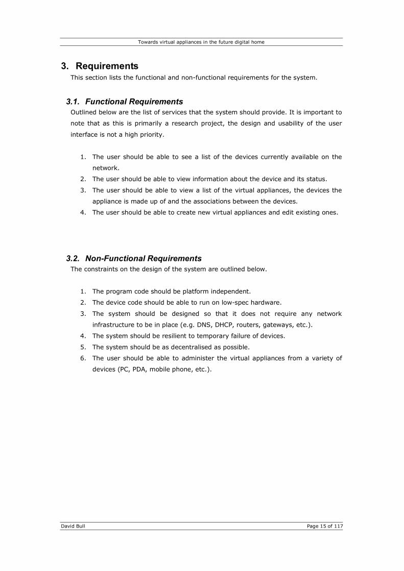
3. Requirements This section lists the functional and non-functional requirements for the system.
3.1. Functional Requirements Outlined below are the list of services that the system should provide. It is important to
note that as this is primarily a research project, the design and usability of the user
interface is not a high priority.
1. The user should be able to see a list of the devices currently available on the
network.
2. The user should be able to view information about the device and its status.
3. The user should be able to view a list of the virtual appliances, the devices the
appliance is made up of and the associations between the devices.
4. The user should be able to create new virtual appliances and edit existing ones.
3.2. Non-Functional Requirements The constraints on the design of the system are outlined below.
1. The program code should be platform independent.
2. The device code should be able to run on low-spec hardware.
3. The system should be designed so that it does not require any network
infrastructure to be in place (e.g. DNS, DHCP, routers, gateways, etc.).
4. The system should be resilient to temporary failure of devices.
5. The system should be as decentralised as possible.
6. The user should be able to administer the virtual appliances from a variety of
devices (PC, PDA, mobile phone, etc.).

Towards virtual appliances in the future digital home
David Bull Page 16 of 117
4. Technical Discussion Two steps are required if everyday appliances are to be decomposed and present their
core functions as services on the network. Firstly the appliances will require a
microprocessor that can control the hardware of the appliance and can communicate
over the network. Secondly, a service discovery protocol is required to aid devices in
discovering and utilising services that they require.
In the first half of this section a range of hardware platforms suitable for embedding in
a variety of appliances are described. Each of these platforms have different
architectures, form-factors and computational power. The platforms that are described
are TINI boards, SNAP boards, PC/104 and MiniITX.
The second half of this section examines a number of currently popular service
discovery protocols including Rendezvous, UPnP, Salutation and Jini.
4.1. Hardware Platform
4.1.1. TINI Board TINI stands for Tiny InterNet Interface and is a platform developed by Dallas
Semiconductor. TINI is “designed to provide system designers and software
developers with simple, flexible and cost effective means to design a wide variety of
hardware devices able to connect directly to corporate and home networks.” [5].
The platform uses a Java programmable runtime environment and the chipset
provides networking capabilities and device level communications. The TINI board
comprises of a DS80C390 microcontroller clocked at 40MHz, 512kB of flash memory
for critical system code and is available with either 512kB or 1MB of NV SRAM [6].
Figure 6 – A TINI board connected to a development board for access to Serial, CAN, Ethernet and 1-Wire busses.

Towards virtual appliances in the future digital home
David Bull Page 17 of 117
The TINI has Serial, CAN, 1-Wire, Ethernet and Parallel I/O allowing it to
communicate with a wide range of devices from small sensors and actuators to
factory automation equipment. Through the use of the TINI board these devices can
then be monitored and controlled remotely or managed directly by a control
program running on the TINI.
A large number of 1-Wire devices, known as iButton’s, are available from Dallas
Semiconductor. An iButton is a small 16mm stainless steel can with a computer chip
inside. Many varieties of iButton are available such as identification, memory,
real-time clock and temperature loggers. 1-Wire ADC and relay boards are also
available permitting use of other types of sensors and the ability to control large
devices.
Example applications of the TINI technology include the deployment of simple
sensor networks, the creation of a basic weather station with the use of the 1-Wire
Weather Station Experimenter’s Kit [7], and control of simple devices through ADCs
and DACs over the 1-Wire bus.
Figure 7 – An iButton

Towards virtual appliances in the future digital home
David Bull Page 18 of 117
4.1.2. SNAP Board SNAP stands for Simple Network Application Platform and is developed by a
company called Imsys. SNAP is a “network-ready, Java-powered plug & play
reference platform and is ideal for remote control, data processing and managing of
everything from small sensors to advanced surveillance factory equipment.” [8].
The SNAP board is very similar to the TINI board from Dallas Semiconductor
described in the previous section. In fact, the SNAP is pin-for-pin compatible with
the TINI and therefore plugs into the same development board allowing it the same
access to Serial, CAN, 1-Wire, Ethernet and Parallel busses. The advantages of the
SNAP over the TINI are that it is J2ME-CLDC compliant and has been certified by
Sun Microsystems. The SNAP board is approximately 12x faster than the TINI in
benchmarks performed by Imsys. The SNAP comes with 2Mb flash memory
compared with 512Kb, and has 8Mb DRAM compared with 512Kb/1Mb NV SRAM.
As well as the increased memory capacity the SNAP board also uses Imsys’ own Cjip
microprocessor clocked at 66MHz. The Cjip “microprocessor minimises the need for
external controller hardware, i.e. the B.O.M., by doing parts of peripheral controller
work (e.g. Ethernet MAC layer), internally in low-level microcode. Similarly, it
executes Java bytecode without needing any accelerator hardware or software
interpreter or JIT compiler.” [9].
Figure 8 – SNAP Board
Figure 9 – The Cjip
microprocessor

Towards virtual appliances in the future digital home
David Bull Page 19 of 117
4.1.3. PC/104 PC/104 is a standard for PC-compatible modules that can be stacked together to
create an embedded computer system [10]. The PC/104 system was developed in
the late 1980s by a Californian based company called Ampro Computers. A
specification was then published in 1992, and now over 150 vendors manufacture
PC/104 products [11]. PC/104 gets its name from the fact that the systems are very
similar to standard desktop PCs, except that they use a different form factor, and
that the systems can be stacked together using a 104 pin connector.
PC/104 system typically consists of a CPU board and then a number of modules that
provides additional features such as serial communications, network interfaces,
video cards, digital and analogue I/O, sound, DSP, etc. Various CPU boards are
available that use CPUs ranging from 8088s through to Pentiums. Because PC/104
systems are essentially standard PCs most PC programs and development tools can
be used.
Power consumption for PC/104 modules is typically between 1-2 watts making them
ideal for embedded systems. Additionally the modules measure only 3.6 by 3.8 by
0.6 inches and are designed to be much more rugged then their standard PC
counterparts [10].
Figure 10 – A typical PC/104 stack

Towards virtual appliances in the future digital home
David Bull Page 20 of 117
4.1.4. Mini-ITX Mini-ITX is a motherboard form factor created by VIA, rather than a complete
computer or embedded board. Mini-ITX differs from other motherboard form
factors, such as ATX, because it is by far the smallest measuring just 6 inches
square. Virtually everything from sound to video, serial, networking and USB is
included on the motherboard meaning that PCI expansion cards are not required.
Unlike normal PC motherboards the CPU is soldered to the board. This is because
the CPU has been specially designed by VIA to run cooler and consume less power
than standard Intel or AMD CPUs. A Mini-ITX PSU is rated at less than 100 watts
compared to 350 watts for a typical desktop PC. Also most Mini-ITX based PCs are
fan-less resulting in very small and very quiet computers.
The CPUs available for Mini-ITX are currently based on either the C3 or Eden
architecture. Neither architecture provides the raw performance of Intel or AMD
architectures, although the more recent C3 processors have a performance similar
to Intel Celeron processors of the same clock speed. Mini-ITX PCs are more suited
to Audio/Video playback and network routing and firewalling [12].
Figure 11 – VIA EPIA M10000 Mini-ITX Motherboard

Towards virtual appliances in the future digital home
David Bull Page 21 of 117
4.1.5. Conclusion In the first half of this section a range of hardware platforms suitable for embedding
in appliances have been examined.
The SNAP and TINI boards are both low-power, small form-factor devices aimed at
controlling a variety of hardware and at the deployment of sensor networks. As both
these boards plug into the same development board they both have access to the
same IO busses. Both boards use the Java programming language, which allows for
rapid development of fairly large and complex programs. Where these two boards
differ though is in the amount of memory and processing power available. As stated
in section 4.1.2, the SNAP boards out performs the TINI board in a range of tests by
a factor of 12 in benchmarks performed by Imsys. However the TINI board is
available for £36 compared with £69 for the SNAP. As mentioned in section 2.2.1
the University of Essex use SNAP boards in their iDorm as well as in their
pDorms/mDorms (plant dormitories). If cost is not a major constraint then the SNAP
board is defiantly worth the extra money for the increased memory capacity and
processing power.
For slightly more demanding appliances, a PC/104 stack may be more suitable. As
described in section 4.1.3, PC/104 is based around the standard IBM PC architecture
and uses processors ranging from 8088s through to Pentiums. PC/104 kits are
available for specific applications such basic as IO, through to high performance
multimedia, however depending on the required configuration of the system they
can cost more than a typical desktop PC.
MiniITX differs from the other hardware platforms discussed, as it is basically a
standard PC motherboard albeit in a much smaller form-factor. Therefore memory,
a storage device and a suitable enclosure will also need to be purchased to build a
complete system, although it is possible to buy pre-built systems. Because a
MiniITX system is a PC it is much more suited to computer based appliances such as
home entertainment systems or network appliances such as firewalls, routers and
servers. A typical MiniITX system based around a 600MHz CPU and complete with a
40Gb hard disk, DVD/CDRW drive, 256Mb DDR RAM and Red Hat Linux preinstalled
costs around £375.

Towards virtual appliances in the future digital home
David Bull Page 22 of 117
4.2. Service Discovery Protocols
4.2.1. Rendezvous Rendezvous is a networking technology developed by Apple.
Rendezvous, also known as Zero Configuration networking, enabling
automatic discovery of computers, devices, and services on IP
networks. Rendezvous enabled devices can allocate IP addresses
without a DHCP server, translate between names and IP addresses without a DNS
server and locate and advertise services without using a directory server. Although
developed by Apple, Rendezvous is an open standard and works with standard non-
proprietary IP networks and equipment. Source code is freely for Rendezvous as
well as software for Windows, Linux, UNIX, VxWorks and Pocket PC 2003 systems.
[13].
Rendezvous makes uses of multicast traffic and as such only works on a network
subnet making it ideal for ad-hoc local networking. When a Rendezvous enabled
device is added to a network it must configure its IP address so that it can
communicate with other devices. To do this it first tries sending a DHCP request and
will use the IP address returned by a DHCP server if one is present. If a response is
not received the device will then use link-local addressing. Here the device randomly
selects an address from the predefined range of addresses set aside for link-local
addressing (169.254.xxx.xxx). The devices then uses ARP to check whether the
chosen address is already in use. If it is already in use the device then randomly
selects another address and then checks again.
Once the device has configured itself with an IP address is must then give itself and
its services unique names on the network. Theses are usually based on the name of
the device (e.g. HP DeskJet 930C). In the event of a name clash the last two bytes
of the devices MAC address are appended to the name. Now the device has an IP
address and a name it needs advertise its services to the network. To do this
Rendezvous uses a variant of the DNS system known as mDNS-SD (multicast DNS-
Service Discovery). The device sends a multicast message with its IP address, port
number, name, services and other any other optional information. Every device on
the network receives this network and stores the information.

Towards virtual appliances in the future digital home
David Bull Page 23 of 117
At some point devices may need to know about the services offered by other
devices. In order to do this the device must query the network for services of the
type it requires, for example, a PC may need to know what printers are available. All
devices on the network receive this query, but only the ones implementing the
requested service respond. To reduce network traffic and increase efficiency the
responses are also sent multicast so that every device receives them. Every device
then saves the response to the query so that at a later stage if they need the same
information they do not have to send a duplicate query as they already have the
information.
Security was a top priority when Apple where designing Rendezvous. As Rendezvous
makes use of standard protocols Rendezvous relies on the security built into those
protocols. Also, as Rendezvous is open source it benefits from the fact that
hundreds of programmers can examine the source code and identify bugs and
vulnerabilities and then put updates back into the community.
It is important to note however that Rendezvous only provides a mechanism for
devices to discover each other. Once a device has discovered a service that it
requires communication takes place using standard protocols.

Towards virtual appliances in the future digital home
David Bull Page 24 of 117
4.2.2. UPnP UPnP stands for Universal Plug and Play and is an open standard
being pushed mainly by Microsoft and Intel although the UPnP
forum created in June 1999 currently consists of more than 656
consumer electronics, computing and security companies [14].
Universal Plug and Play may sound very similar to the Plug and Play technology that
Microsoft built into Windows, but the similarities end there. UPnP is a distributed,
open networking architecture that employs existing Internet protocols, such as
TCP/IP, HTTP and XML, to enable discovery and control between devices regardless
of their operating systems and programming languages [15]. A number of UPnP
stacks are currently available for C and Java from Intel, Siemens and currently one
open source project.
UPnP devices are logical containers with specified device types. Each UPnP device
contains a number of related services each with its own unique service type. Each
service contains a number of actions, similar to remote procedure calls, each of
which reference service-defined state variables [16]. To aid interoperability between
devices from different vendors the UPnP Forum has drawn up a number of device
and service definitions giving specific types of device a standard interface.
Figure 12 – UPnP devices in the digital home

Towards virtual appliances in the future digital home
David Bull Page 25 of 117
UPnP devices are passive entities that can be discovered and controlled by UPnP
control points. Devices periodically advertise their presence on the network and can
respond to searches issued by control points. Control points may also invoke actions
on the device and retrieve the status of the device through its service’s state
variables. A service’s state variables can also be evented so that any subscribed
control point receives event messages whenever the value of the state variable is
updated. Control points typically provide the user with access to the device’s
capabilities and status [16].
The five steps to UPnP networking are shown in Figure 14. The first step for any
UPnP enabled device to configure its IP address and this process identical to that of
Rendezvous devices.
The second stage is discovery and is where devices advertise their services to the
network. This is carried out by SSDP (Simple Service Discovery Protocol) which
itself makes use HTTPMU and HTTPU which are variants of the HTTP protocol using
multicast and unicast over UDP. When a device wishes to leave the network it must
cancel its advertisement so that all control points are aware that the device is
leaving. To guard against devices leaving the network without warning the device
advertisements expire and devices should renew their advertisement in order to
maintain a presence on the network.
0. Addressing
1. Discovery
2. Description
5. Presentation 4. Eventing3. Control
Figure 13 – UPnP Control Points, Devices and Services
UPnP Enabled DeviceUPnP Enabled Device
Device
Service 1 Actions State Variables
Service 2 Actions State Variables Control Point
UPnP Control Point
Device
Service 1 Actions State Variables
Figure 14 – Steps to UPnP networking

Towards virtual appliances in the future digital home
David Bull Page 26 of 117
The discovery stage also deals with control points wishing to find specific devices or
particular types of devices or services. When a UPnP control point starts it uses
SSDP to send a multicast query to discover all the devices currently present. Each
device will then send unicast responses using SSDP to the control point. Once the
control point has sent its query it should not normally need to send further queries
as it will receive advertisements from new devices automatically as they join the
network.
Once a control point has discovered a device that it is interested in it then needs to
get a description of the device and the services that it provides. This is the third
stage in UPnP networking. The device’s advertisement and query response
messages contain a URL which points to an XML description document on the
device. The description document is retrieved using standard HTTP over TCP/IP. The
device description document includes vendor-specific information, manufacturer
information, model name, serial number and URLs to the vendor and product web
pages. The description document also contains a list of any embedded devices and
services along with URLs for control, eventing and presentation.
Now that the control point has knowledge of the device and its services it can
invoke actions provided by those services and poll the status of the services state
variables. Invoking an action is similar to a remote procedure call where the action
may take and return number of arguments. The control point uses SOAP (Simple
Object Access Protocol) which is an XML based protocol normally used by web
servers in a decentralised, distributed environment to call remote procedures on one
another.
Some of a service’s state variables may be evented. This means that the service
publishes updates whenever the variables change. Once a control point has
discovered and learned about a device and its services it may subscribe to the
service and receive event notifications whenever a state variable is updated. The
event notification uses an extension to HTTP known as GENA (General Event
Notification Architecture) which was defined to provide the ability to send and
receive notifications using HTTP over TCP/IP and multicast UDP. When a control
point initially subscribes to a service it receives it receives an initial update
notification which contains all the state variables that are evented along with their
values allowing the control point to initialise a model of the state of the service. To
prevent services from continually sending event notifications control points must
send a message to cancel the subscription. If however the control point disappears
and fails to cancel its subscription, the subscription will eventually expire and so as
long as the control point wishes to receive events it must renew its subscriptions.
Towards virtual appliances in the future digital home
David Bull Page 27 of 117
The final stage in UPnP networking is the presentation stage. As long as the device
has been discovered and its description document contains a valid presentation URL
then the presentation page can be viewed in a standard web browser. The
presentation page typically represents the state of the device and may allow the
user to control the device, however the UPnP forum places no requirements on the
presentation page other than that it is written in HTML and delivered using HTTP
over TCP/IP.
The current version of UPnP has left security to one side for the time being, but as
with Rendezvous, because UPnP makes use of standard Internet protocols it relies
on the security built into those protocols. The second version of UPnP, currently
being drafted by the UPnP forum, is said to include encryption and access control.

Towards virtual appliances in the future digital home
David Bull Page 28 of 117
4.2.3. Salutation Salutation is another service discovery protocol and is an open
architecture being developed by the Salutation Consortium.
However, where as both Rendezvous and UPnP make use of
existing Internet protocols and an IP network, Salutation is
truly independent of the operating system, programming
language, communications protocol and hardware platform. It does not require a
specific programming language, as does Jini, nor does it make use of protocols such
as UDP or HTTP. Salutation is able to operate over any communication system
including IP, IrDA and Bluetooth [17].
The Salutation architecture is shown in Figure 15. The Salutation Manager acts as a
service broker for applications and services called Network Entities. A Network
Entity may be a client, a service provider or both. When a service provider joins the
network it registers its capabilities with its local Salutation Manager. The Salutation
Manager allows Network Entities to discover and use services provided by other
Network Entities. The Salutation Manager also provides a transport independent
interface to the Network Entities through the SLM-API (Salutation Manager
Application Program Interface). The Salutation Managers communicate with each
other using SMP (Salutation Manager Protocol) which makes use of Sun
Microsystems’ Open Networking Computing Remote Procedure Call version 2
protocol in order to perform their role as service brokers [18].
The Salutation Manager provides a transport independent interface known as the
Salutation Transport Interface (SLM-TI) to transport dependent entities called
Transport Managers (TM). The Transport Manger allows the Salutation Managers to
be transport independent and a Salutation Manager may utilise one or more
Transport Managers. The Transport Managers discover other Salutation Managers
connected to the same transport. For each remote Salutation Manager that the
Transport Manger discovers, it registers the with the local Salutation Manager.
Figure 15 – The Salutation architecture
Salutation Manager
TM TM
SLM-API
TCP/IP IrDA
TM
SLM
Server Client Client Server
TM
SLM
Client
TCP/IP IrDA
Salutation Manager Protocol

Towards virtual appliances in the future digital home
David Bull Page 29 of 117
Clients discover services that they are interested in by querying their local
Salutation Manager. The Salutation Managers then co-ordinate and return results.
Once the client has identified the service that it is interested in it can then retrieve
the service description.
Services can be subdivided into functional units. For example a print service will
probably contains just one functional unit called ‘Print’, but a fax service may
contains several functional units such as ‘Print’, ‘Scan’ and ‘Send’. Attribute records
are used to describe these functional units.
Once the client has the description of the service it may then use the functions
provided by that service. To do this the Salutation Manager establishes a Service
Session (a virtual data pipe) between the client and the service. Commands,
responses and data are exchanged between clients and services on these data pipes
in blocks called Messages. The format of these messages and protocol is known as
Personality Protocols.
Unlike both Rendezvous and UPnP, Salutation does not address the issue of network
configuration because of its transport independent design. Also, it would not be easy
to design a generic solution to this problem that worked on all transports.
Salutation addresses the issue of security by providing user authentication through
the use of a user-id and password scheme.
Client describes the requirements of the services it wishes to use in a Service Description Record and passes it to the Salutation Manager.
Server describes its capability in a Functional Unit Description Record and registers it with the Salutation Manager.
The Salutation Manager sends back a Service Description Record that indicates what services are actually available in response to query.
Client Salutation Manager
Salutation Manager
Functional Unit
Query Capability Call
Register Capability
Query Capability Reply
Figure 16 - The use of Service and Description Records

Towards virtual appliances in the future digital home
David Bull Page 30 of 117
4.2.4. Jini Jini is Sun Microsystems’ Java based connection technology that makes it possible
for various devices to form dynamic local area networks and offer services to each
other. Jini uses the term federation to refer to groups of devices.
The notion of services is a key concept in Jini, and is an entity that can be used by a
person, a program or another service. A Jini system consists of services that can be
collected together for the performance of a particular task. Services may be added
or removed from a federation at any time.
Services communicate with each other using a service protocol which is defined by a
set of Java interfaces. The service protocols are completely open and Jini only
defines a number of service protocols for critical service interaction. These service
protocols run on top of Java Remote Method Invocation (RMI).
A lookup service is used by clients to find services that they require. The lookup
service is the major point of contact between the system and its users. The role of
the lookup service is to map interfaces indicating the functionality provided by a
service to sets of objects that implement the service. Additionally, descriptive
entries may be associated with services to provide easier identification and selection
of services by people. As well as storing lookup information for services a lookup
service may include references to other lookup services to provide a hierarchical
lookup system.
When a service starts up or is newly added to a Jini system it must locate and
register itself with a lookup service. This discovery and registration takes place
using two protocols known as ‘Discovery’ and ‘Join’. To locate a lookup service the
service sends a multicast request to the local network asking for any lookup services
to identify themselves. Once a lookup service has responded the service may then
register itself by creating an object of the same type as itself and an array of lookup
entry instances that specify attributes to describe the capabilities of the service and
passing these as parameters to the lookup services register method. As with UPnP
registrations expire after a set period and the service will need to renew its
registration to maintain a presence on the network. Once a registration expires the
lookup service removes the entry for that service.

Towards virtual appliances in the future digital home
David Bull Page 31 of 117
A client wishing to use a service must, in the same was as a service, first discover
the lookup services on the local network. Once the client has discovered a lookup
service it must then pass a template to the lookup service which is used to filter the
set of known services. This template specifies the type of service required as well as
a list of attributes specifying the required capabilities of the service. The lookup
service then returns an array of matching services in the form of service objects. It
is then up to the client to choose a service or further filter the results.
Once a service has been selected the client communicates directly with the service
by invoking the available methods. As with UPnP, the client may also register with
the service to receive notifications when the state of the service changes. All of this
communication and event notification takes place using Java RMI.
Although a lookup service would normally be available, Jini is capable of operating
with no lookup service available. In this situation clients use a technique called peer
lookup. This technique involves the client sending out the same identification
message used by a lookup service to request services to register with the client as
though it were a lookup service. The client can then select the service required from
the registration requests and drop or refuse the rest [19].
As Java is a platform independent programming language it is unable to perform
system calls required to configure a device’s network configuration. As such Jini
does not address the issue of network configuration and assumes that the device is
either already configured or is capable of configuring itself.
For security Jini makes use of access control lists to determine which clients may
use which other services. Also, as Jini uses RMI for communication it also relies on
the security policies built into RMI.

Towards virtual appliances in the future digital home
David Bull Page 32 of 117
4.2.5. Conclusion The second half of this section has looked at four popular service discovery
protocols, namely Rendezvous, UPnP, Salutation and Jini.
Rendezvous appears to have been designed for computers to discover devices such
as network printers and other computers. Rendezvous enables networks to be
created without any perquisites for existing infrastructure, however once devices
have discovered services they require they communicate out-of-band using their
own protocols.
UPnP is very similar to Rendezvous in terms of its zero configuration of the network
and service discovery routines. However UPnP provides a form of RPC where devices
can invoke actions and subscribe to events offered by remote services. This does
not appear to be possible with Rendezvous. Another advantage of UPnP is the
number of UPnP enabled devices that already exist. At the moment though these
are mainly ADSL routers and modems, however with Microsoft and Intel along with
at least another 150 manufacturers backing UPnP it is almost certain that were will
be plenty more UPnP enabled devices in the near future. Even the University of
Essex’s iDorm and the University of Cambridge’s AutoHAN project use UPnP, and as
mentioned in section 4.2.2 a number of UPnP stacks are freely available.
Where as Rendezvous, UPnP and Jini all require a TCP/IP network, Salutation is truly
transport independent enabling it to work over IrDA and Bluetooth as well.
Salutation is also platform and programming language independent making it the
ideal choice for heterogeneous networks, however no source code or stacks seem to
be available at the time of writing.
Jini is Sun Microsystems’s offering and as such is entirely Java based. While this
allows it to be platform independent it places the constraint that all devices must be
written in Java, especially as Jini makes heavy use of RMI. Another drawback is that
Jini appears to be far too heavyweight for small embedded devices such as TINI and
SNAP boards. Also, although Jini can operate in peer-to-peer mode, a typical Jini
system relies on lookup services and as such is not as decentralised as Rendezvous
and UPnP.

Towards virtual appliances in the future digital home
David Bull Page 33 of 117
5. Design
5.1. Devices In order to demonstrate the concept of creating virtual appliances a number of
different devices will need to be designed. A few of these will be stand-alone devices
such as lights and switches. Some more complex devices containing sub-components
will also be designed to show the concept of decomposing appliances into their core
functions.
These devices will be designed using UPnP for the reason described in section 4.2.5;
including availability of stacks and source code, and because of the number of UPnP
enabled devices already available. UPnP also meets the non-functional requirements
listed in section 3.2 because of its platform independence, its non-requirement for pre-
existing network infrastructure, and its ability to run on reasonably low-spec hardware
such as SNAP boards. The program code will be written using Java to allow platform
independence.
Most of the devices will be simulated and run on a PC, however depending on time
constraints a few simple devices may be built using SNAP boards with external sensors
and actuators to better convey the concept of virtual appliances.
5.2. User Interface As a wide range of devices should be able to manage the virtual appliances, such as
PCs, PDAs and mobile phones, it is inconceivable to design and create numerous
applications to run on each of the client devices. However, almost all of these devices
have a web browser and are therefore capable of displaying web pages. The advantage
of this approach is that not even a single line of code has to be written for these client
devices, although it does require a server to be available. The use of a server in an
otherwise decentralised environment is not ideal although the devices themselves will
still function without the server, as it is only required by the user to manage them.
Using a web server to handle client requests for managing the devices has simplified
the design of the interface application, however the issue of displaying information on
such a variety of screen sizes is now present. One solution exists in the form of The
Apache Cocoon project which was designed to solve exactly this kind of problem.

Towards virtual appliances in the future digital home
David Bull Page 34 of 117
Cocoon is an XML publishing framework written in Java on top of SAX (Simple API for
XML) and XSL (Extensible Stylesheet Language). Unlike HTML, which defines how text
should be laid out, XML can be used to represent the actual content of a document
allowing applications to very quickly scan through a document and extract the required
sections. Unfortunately XML does not deal with how the content of the document of
should be displayed and this is where XSL comes in. XSL, like CSS, is a stylesheet
language, however XSL is much more then CSS because it gives the ability to
completely transform XML documents. Generally XSL transforms XML documents from
one XML-based language to another, such as XHTML, however through the use of XSL
Formatting Objects, XML documents can be transformed into a variety of different
formats such as Word documents or PDF documents for example.
This is ideal for tailoring information to the display capabilities of client devices without
having to have multiple versions of a document. Also, as new devices appear with
different display capabilities a new XSL document can be created and instantly the
information can be tailored for that display without having to re-produce all the
information in yet another format and without any re-coding. Another advantage of
Cocoon is that it is written in Java and runs as a servlet meaning that it is platform
independent.
5.3. Device Management Application As Apache Cocoon runs as a servlet it would be sensible to use the Apache Tomcat
server to run Cocoon on and also to design the UPnP device management application
as a servlet to run on Tomcat. Because of the use of Cocoon, the role of the device
management application is greatly reduced, it’s job now being simply to communicate
with the UPnP devices on the network and return XML documents to Cocoon for styling
for the particular client devices.
To comply with the functional requirements listed in section 3.1 the device
management application must be able to provide a list of the UPnP devices currently on
the network along with detailed information about the individual devices. It must also
provide the ability to manage the associations between devices used in creating virtual
appliances.
Figure 17 - How Apache Cocoon transforms an XML document
XML Document transformation XHTML Document
Transformation Rules

Towards virtual appliances in the future digital home
David Bull Page 35 of 117
5.4. Rules Rules will need to be used to create associations between individual devices. It is these
associations that form the virtual appliance. The simplest example would be a switch
and a light where a rule tells the light to change state as the switch does. These rules
could be stored on a central server which then subscribes to devices in order to receive
state change events and fires rules associated with those events, however this requires
the server to be reliable.
An alternative solution is to store the rules on the individual devices. The rules could be
stored on the output devices as these would usually have more computational power
than simple sensor devices. This means that the rules are distributed amongst the
devices so there is no single point of failure. This approach requires devices to
implement a special service to handle the rules. Obviously existing UPnP devices will
not have this service and so to remain compatible with these devices a service that can
handle rules on behalf of other devices is required. This service could be provided by a
dedicated server or provided by other devices in a similar way to how the lookup
service is provided by devices in Cambridge’s AutoHAN system.
The user creates rules through the web-based interface when configuring virtual
appliances. Therefore rules should be kept relatively simple so that the user interface is
not overly complicated. This is especially important on hand-held devices that have a
limited display area.
Ideally the rules could be defined using an XML based language, however this requires
a lot of processing for low-power embedded boards such as SNAP and TINI boards.
Lightweight XML parsers do exist for these boards, but as the boards will already be
running the UPnP stack and the device code there would not be much memory or
processing time spare for XML parsing.
Another solution is to define a syntax for rules that is not based on XML. An example of
a rule used in an AutoHAN system is show below.
Rule tv-mute => TVOn(TVID) -> (telephone-rings(PHONEID) | door-bell(DOORID)) - TVOff(TVID); { TVID.AudioOut.mute(); }
This rule states that the television volume is should be muted if the telephone or the
door bell rings. The problem with rules such as this is that the application must
understand semantics such as “telephone-rings” and “door-bell” [4]. The meaning of
these semantics could be hard coded but then new types of devices could not be added
without modifying the code of the other devices.

Towards virtual appliances in the future digital home
David Bull Page 36 of 117
What is needed is a simple IF-THEN type rule that will work with any type of device.
With UPnP the state of a particular service is available through the service’s state
variables. Invoking actions on the service can also change the state of the service.
UPnP devices and services are identified on the network through unique Ids, but can
also be grouped by type. Therefore rules can be built around the ID of a device, the ID
of one of its services and then either one of the services state variables or actions. The
rules can then be constructed by the user through the web interface by way of
selection boxes for the device, service, state variable, action and associated values.
Rules could then be sent to devices through UPnP actions where each part of the rule is a separate argument. For example, the following rule states that when the switch with ID 123 is in position 1, the light with ID 456 will turn on:
Input Device ID 123 Service ID Switch.1 State Variable Position Value 1
Output
Device ID 456 Service ID Light.1 Action Power Value 1
5.5. System Architecture An overview of the system architecture is shown in Figure 18. The Virtual Appliance Management application communicates with the UPnP devices and exports information in XML. When a client wishes to view the state of or manage the virtual appliances Cocoon applies a particular XSL stylesheet to the XML data from the management application depending on the display capabilities of the client.
Figure 18 – System Architecture Diagram
Virtual Appliance Management Application
Light Bulb
Timer
Switch
UPnP Devices
UPnP
PC
PDA Mobile Phone
Clients
HTML, WMLXML XSL
UPnP Control Point
Apache Cocoon Web Publishing Framework

Towards virtual appliances in the future digital home
David Bull Page 37 of 117
6. Implementation
6.1. Introduction This section covers the implementation of the Virtual Appliance system including
numerous devices and the management servlet. As stated in the design section UPnP
will be used for the service discovery protocol to allow devices to discover each other
and for the management application to control the devices. The management
application will be written as a Java Servlet running on top of the Apache Tomcat
server. Tomcat will also run Apache Cocoon which will be used to tailor the XML
documents from the management applications for the specific client devices.
All the program code is written using Java for platform independence. The specific
UPnP stack used is the Siemens UPnP Java Stack v1.0.1. All coding is carried out using
the freely available and open source Eclipse project and all code is self-authored (i.e.
no auto-generated or wizard-generated code has been used).
6.2. Devices
6.2.1. Light Bulb The UPnP Light Bulb device is a simple representation of a light bulb
that can be turned on or off. As this device is an output device it
implements the device association service, described later, allowing it to
associated with other devices and store rules.
6.2.1.1. UPnP Device and Service Description The UPnP Light Bulb (urn:www-uk-dave-com:device:LightBulb:1) is typically a
root device and apart from the device Identification and Association services,
described later, only implements one service.
The Power service (urn:www-uk-dave-com:service:Power:1) contains the following
state variables:
Variable Name Data Type Default Value Evented?
Power Boolean 0 Yes A_ARG_TYPE_Boolean Boolean 0 No
Table 1 – Power Service State Variable table
State Variable Power reflects the current state of the power to the light.
A_ARG_TYPE_Boolean is merely a Related State Variable for the SetPower()
action.

Towards virtual appliances in the future digital home
David Bull Page 38 of 117
The Power service also defined the following actions:
Arguments Action Name
Name Direction Related State Variable GetPower Power Out Power SetPower Power In A_ARG_TYPE_Boolean TogglePower
Table 2 – Power Service Action table
Action GetPower() simply returns the state of the power to the light, where as
SetPower() sets the power to the light to a specific state. TogglePower() simply
toggles the power to the light and does not take any arguments.
6.2.1.2. Java Code The UPnP Switch device consists of the following Java Classes:
• LightDevice
This class is the main class for the UPnP Light Bulb. It initialises the UPnP
stack, loads the device settings (port, device ID, identification), creates
the device description and service and announces the device to the
network.
• PowerService
This class implements the Power service for the UPnP Light Bulb. It
maintains the State Variables and handles the Actions.
• LightDevicePresentationPageHandler
This class implements the UPnP presentation page allowing the state of the
device to be viewed using web browser. The page simply displays an
image of the light either on or off depending on its current state.
• LightDeviceUI
This class contains a minimal GUI for the light bulb simply displaying an
image of the current state of the device in a window.
• AssociationManager
• AssociationService
• Rule
• UPnPDeviceStore
• IdentificationService
• UUIDGen
This class generates random UUIDs. This is used then the device starts up
for the very first time, or when its configuration file is deleted.

Towards virtual appliances in the future digital home
David Bull Page 39 of 117
6.2.2. Switch The UPnP Switch device is a simple representation of a toggle
switch having just two states. When the switch is clicked, either
through the on screen GUI, or through the presentation page, the
state of the switch toggles.
6.2.2.1. UPnP Device and Service Description The UPnP Switch (urn:www-uk-dave-com:device:Switch:1) is typically a root
device and apart from the device Identification service, described later, only
implements one service.
The Switch service (urn:www-uk-dave-com:service:Switch:1) contains the
following state variables:
Variable Name Data Type Default Value Evented?
State Boolean 0 Yes
Table 3 – Switch Service State Variable table
State Variable Switch reflects the current state of the switch.
The Switch service also defines the following actions:
Arguments Action Name
Name Direction Related State Variable GetState State Out State
Table 4 – Switch Service Action table
Action GetState() simply returns the state of the switch.

Towards virtual appliances in the future digital home
David Bull Page 40 of 117
6.2.2.2. Java Code The UPnP Switch device consists of the following Java Classes:
• SwitchDevice
This class is the main class for the UPnP Switch. It initialises the UPnP
stack, loads the device settings (port, device ID, identification), creates
the device description and service and announces the device to the
network.
• SwitchService
This class implements the Switch service. It maintains the State Variables
and handles the Actions.
• SwitchPresentationPageHandler
This class implements the UPnP presentation page allowing the state of the
switch to be viewed using web browser. The page simply displays an
image of the switch in its current state, and when clicked the state is
toggled.
• SwitchUI
This class provides a minimal GUI for the switch simply displaying an
image representing the current state of the switch which, when clicked,
toggles.
• IdentificationService
• UUIDGen
This class generates random UUIDs. This is used then the device starts up
for the very first time, or when its configuration file is deleted.

Towards virtual appliances in the future digital home
David Bull Page 41 of 117
6.2.3. Timer The UPnP Timer device is a simple timing device.
The duration can be set and the timer started and
stopped. Event notifications are sent when the timer
has started counting and when it has finished. As
this device is an output device it implements the
device association service, described later, allowing it to associated with other
devices and store rules.
6.2.3.1. UPnP Device and Service Description The UPnP Switch (urn:www-uk-dave-com:device:Timer:1) is typically a root
device and apart from the device Identification and Association services, described
later, only implements one service.
The Timer service (urn:www-uk-dave-com:service:Timer:1) contains the following
state variables:
Variable Name Data Type Default Value Evented?
AlarmURL String http://[deviceIP]/alarm.mp3 No Duration Integer 0 No Finished Boolean 1 Yes Remaining Integer 0 No A_ARG_TYPE_int Integer 0 No
Table 5 – Timer Service State Variable table
State Variable AlarmURL contains a URL to an MP3 file to be used by a UPnP Audio
Playback device. Duration reflects the initial duration of the timer, where as
Remaining reflects how much time is left. Finished is set to true when the timer is
not running and false when it is. Finished is also evented so that subscribed
devices receive a notification when the timer starts and stops timing. The
A_ARG_TYPE_int variable is a Related State Variable for the SetDuration() action.

Towards virtual appliances in the future digital home
David Bull Page 42 of 117
The Timer service also defines the following actions:
Arguments Action Name
Name Direction Related State Variable GetDuration Duration Out Duration SetDuration Duration In A_ARG_TYPE_int GetRemaining Remaining Out Remaining GetFinished Finished Out Finished GetAlarmURL URL Out AlarmURL Start Stop
Table 6 – Timer Service Action table
GetDuration simple returns the initial duration of the timer in seconds. SetDuration
is used to set the duration of the timer in seconds and takes one argument. Get
Remaining returns the number of seconds left on the timer. GetFinished returns
false if the timer is currently running, true otherwise. Start is used to start the
timer, and Stop is used to stop it.
6.2.3.2. Java Code The UPnP Timer device consists of the following Java Classes:
• TimerDevice
This class is the main class for the UPnP Timer. It initialises the UPnP
stack, loads the device settings (port, device ID, identification), creates
the device description and services, and announces the device to the
network.
• Timer
This class contains the actual timing code. It extends the Thread class and
contains methods for starting, stopping, setting duration, adding an action
listener, etc.
• TimerListener
This interface is used to provide events to classes wishing to receive
notifications when a Timer stops and starts.
• TimerService
This class implements the Timer service. It maintains the State Variables
and handles the Actions.
• TimerDevicePresentationPageHandler
This class implements the UPnP presentation page allowing the state of the
timer to be viewed and configured using web browser. The page displays
an image of the timer in its current state, and includes buttons to start and
stop the timer as well as set the duration. The page automatically
refreshes every second when the timer is running.

Towards virtual appliances in the future digital home
David Bull Page 43 of 117
• TimerDeviceUI
This class provides minimal GUI for the timer device using a
TimerUIPanel.
• TimerUIPanel
As the timer uses a fixed layout with custom widgets it has been realised
in a separate class extending JPanel. This class shows the current state of
the timer as was as providing buttons to start and stop the timer as well as
set the duration.
• SetTimeDialog
This is a basic class that extends JDialog to allow the user to enter a
duration for the timer.
• AssociationManager
• AssociationService
• Rule
• IdentificationService
• UPnPDeviceStore
• UUIDGen
This class generates random UUIDs. This is used then the device starts up
for the very first time, or when its configuration file is deleted.

Towards virtual appliances in the future digital home
David Bull Page 44 of 117
6.2.4. Motion Sensor The UPnP Motion Sensor device is a representation of a real life
motion sensor. The sensor reacts to mouse movement over the
window.
6.2.4.1. UPnP Device and Service Description The UPnP Motion Sensor (urn:www-uk-dave-com:device:MotionSensor:1) is a root
device and apart from the device Identification service, described later, only
implements one service.
The Motion Sensor service (urn:www-uk-dave-com:service:MotionSensor:1)
contains the following state variables:
Variable Name Data Type Default Value Evented?
Motion Boolean 0 Yes
Table 7 – Motion Sensor Service State Variable table
The State Variable Motion simply reflects the state of the motion sensor and is
evented so that other device receive notification when motion is detected.
The Motion Sensor service also defines the following actions:
Arguments Action Name
Name Direction Related State Variable GetMotion Motion Out Motion
Table 8 – Motion Sensor Service Action table
GetMotion simply returns the value of the Motion State Variable. This action is not
normally used as device will usually subscribe to the service and then
automatically receive events when motion is detected.

Towards virtual appliances in the future digital home
David Bull Page 45 of 117
6.2.4.2. Java Code The UPnP Motion Sensor device consists of the following Java Classes:
• MotionSensorDevice
This class is the main class for the UPnP Motion Sensor. It initialises the
UPnP stack, loads the device settings (port, device ID, identification),
creates the device description and services, and announces the device to
the network.
• Timer
This class extends Thread to implement a very minimal timer used for
holding the motion status at true for a few seconds after motion has been
detected.
• TimerListener
This interface is used to provide events to classes wishing to receive
notifications when a Timer stops and starts.
• MotionSensorService
This class implements the Motion Sensor service. It maintains the State
Variables and handles the Actions. Motion is detected by the GUI when
then causes a the sensor state to change a timer to start.
• MotionSensorPresentationPageHandler
This class implements the UPnP presentation page allowing the state of the
timer to be viewed using web browser. The page simply displays an image
representing the current state of the motion sensor.
• MotionSensorUI
This class provides minimal GUI for the motion sensor. It also implements
the MouseMotionListener interface, which is used for detecting motion.
When motion is detected the MotionSensorService is informed.
• IdentificationService
• UUIDGen
This class generates random UUIDs. This is used then the device starts up
for the very first time, or when its configuration file is deleted.

Towards virtual appliances in the future digital home
David Bull Page 46 of 117
6.2.5. Camera This is the first non-simulated UPnP device so far. Using the Java
Media Framework this device grabs images from any WebCam
or video capture device supported by the operating system.
Originally it was intended that this device would be
able to stream video, but this turned out to be too
time consuming, so the device simply captures images when
asked and then makes them available through the built in web
server provided by the UPnP stack.
6.2.5.1. UPnP Device and Service Description The UPnP Camera (urn:www-uk-dave-com:device:Camera:1) is a root device and
apart from the device Identification and Association services, described later, only
implements one service.
The Camera service (urn:www-uk-dave-com:service:Camera:1) contains the
following state variables:
Variable Name Data Type Default Value Evented?
LastCaptureTime String null Yes ImageURL String http://[deviceIP]/capture.png No StreamURL String null No A_ARG_TYPE_Boolean Boolean 0 No
Table 9 – Camera Service State Variable table
The State Variable LastCaptureTime contains the time of the last captured image.
This is updated whenever an image is captured and is evented so that other
devices are notified when a picture is taken. The ImageURL variable contains the
URL to the captured image. StreamURL always contains null as streaming has not
yet been implemented, and A_ARG_TYPE_Boolean is a Related State Variable for
the TakeImage() action.
The Camera service also defines the following actions:
Arguments Action Name
Name Direction Related State Variable GetLastCaptureTime LastCaptureTime Out LastCaptureTime GetImageURL ImageURL Out ImageURL GetStreamURL StreamURL Out StreamURL TakeImage Status Out A_ARG_TYPE_Boolean
Table 10 – Camera Service Action table

Towards virtual appliances in the future digital home
David Bull Page 47 of 117
GetLastCaptureTime simply returns the value of the LastCaptureTime State
Variable. This action is not normally used as device will usually subscribe to the
service and then automatically receive events when images are taken.
GetImageURL returns the URL to the captured image contained in the ImageURL
State Variable. GetStreamURL currently returns null as streaming is not
implemented in this version, though it would return the URL to the video stream.
TakeImage is the main action and is called when ever another device wishes the
camera to take a picture. The image can then be retrieved from the ImageURL.
6.2.5.2. Java Code The UPnP Camera device consists of the following Java Classes:
• CameraDevice
This class is the main class for the UPnP Camera. It initialises the camera
and UPnP stack, loads the device settings (port, device ID, identification),
creates the device description and services, and announces the device to
the network.
• CameraController
This class is responsible for communication with the camera through the
Java Media Framework. It takes pictures and saves them to disc.
• CameraService
This class implements the Camera service. It maintains the State Variables
and handles the Actions.
• CameraDevicePresentationPageHandler
This class implements the UPnP presentation page that displays the
previously taken picture along with a button to take a new picture.
• CameraDeviceUI
A minimal GUI for the camera which displays the previously taken picture
along with a button to take a new picture.
• AssociationManager
• AssociationService
• Rule
• UPnPDeviceStore
• IdentificationService
• UUIDGen
This class generates random UUIDs. This is used then the device starts up
for the very first time, or when its configuration file is deleted.

Towards virtual appliances in the future digital home
David Bull Page 48 of 117
6.2.6. mDorm – Temperature and Light Sensor The mDorm (also known as the pDorm) could be
considered as a miniature version of Essex’s iDorm. It
is a cabinet containing a SNAP board with two sets of
lights, a fan, a heater, a temperature sensor and a
light sensor. The mDorm is designed as a purpose
built, fully controllable environment for the remote
care of plants, although it is being used in this project
purely for its sensors and actuators
A number of UPnP devices were written for the mDorm in order to assess the
capabilities of the SNAP board. Some of these test devices simply accessed a single
sensor or actuator, and others accessed multiple sensors and actuators.
Development of the UPnP devices on the SNAP board made use of the SNAP
firmware revision 0.15.1 and an older version of the Siemens Java UPnP Stack.
Version 1.0.0 of the Siemens Java UPnP Stack had to be used as the latest version
would not work on the SNAP because it is not J2ME-CLDC compliant and therefore
uses classes not available on the SNAP. Also, Java code to access the mDorm’s
sensors and effectors was provided on the Essex University CC464 module page
[20]. This code was later modified by myself to improve speed and memory
utilisation. This modified version of this code is given in Appendix D. During testing
the modified version was 2.64 times more memory efficient and 1.72 times faster
than the original code when controlling lights and accessing light and temperature
sensors. The code used to perform these benchmarks is included in the modified
Java class in Appendix D.
During the assessment of the SNAP’s capabilities it became apparent that running
more than two UPnP devices caused memory usage to reach critical levels often
causing the SNAP board to crash requiring a power-cycle to reset it. Based on these
finding it was decided to just UPnP enable the light and temperature sensors in the
mDorm.
During development of the UPnP devices for the mDorm a bug was found in the
java.net.URL class in the SNAP firmware (revision 0.15.1). The problem was with
the toString() method not including a forward-slash (/) between the port number
and the file name in the URL. This caused a NumberFormatException when trying to
determine the port number from the URL because it had merged with the filename.
Imsys (the makers of the SNAP) were informed and within 24 hours a response was
received confirming the bug and stating it would be fixed in the next release.

Towards virtual appliances in the future digital home
David Bull Page 49 of 117
This bug did not prove to be a problem in the development of the mDorm UPnP
devices as it only affected UPnP Control Points. The bug was found whilst testing a
UPnP Control Point on the mDorm which is required by the Association service. As
such, the devices on the mDorm are currently incapable on storing and handling
rules.
6.2.6.1. UPnP Device and Service Description The mDorm device (urn:www-uk-dave-com:device:mDorm:1) is a root device
containing an Identification service and two embedded devices. The two
embedded devices are the temperature sensor (urn:www-uk-dave-
com:device:TempSensor:1) and the light level sensor (urn:www-uk-dave-
com:device:LightSensor:1). Each of these embedded implement only one service;
the temperature sensor service (urn:www-uk-dave-com:service:Temperature:1)
and the light level sensor service (urn:www-uk-dave-com:service:LightLevel:1).
The temperature sensor service (urn:www-uk-dave-com:service:Temperature:1)
contains the following state variables:
Variable Name Data Type Default Value Evented?
Temp Integer 0 Yes
Table 11 – Temperature Sensor Service State Variable table
The State Variable Temp reflects the temperature reported by the actual
temperature sensor inside the mDorm.
The temperature sensor service also defines the following actions:
Arguments Action Name
Name Direction Related State Variable GetTemp Temp Out Temp
Table 12 – Temperature Sensor Service Action table
GetTemp simply returns the value of the State Variable Temp.
mDorm device
Temperature sensor device
Temperature sensor service
Light level sensor service
Identification service
Light level sensor device
Figure 19 - mDorm device and service hierarchy
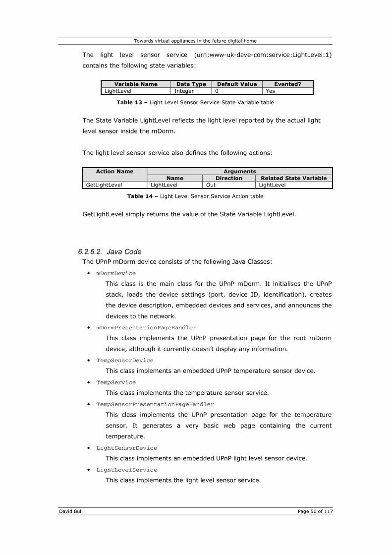
Towards virtual appliances in the future digital home
David Bull Page 50 of 117
The light level sensor service (urn:www-uk-dave-com:service:LightLevel:1)
contains the following state variables:
Variable Name Data Type Default Value Evented?
LightLevel Integer 0 Yes
Table 13 – Light Level Sensor Service State Variable table
The State Variable LightLevel reflects the light level reported by the actual light
level sensor inside the mDorm.
The light level sensor service also defines the following actions:
Arguments Action Name
Name Direction Related State Variable GetLightLevel LightLevel Out LightLevel
Table 14 – Light Level Sensor Service Action table
GetLightLevel simply returns the value of the State Variable LightLevel.
6.2.6.2. Java Code The UPnP mDorm device consists of the following Java Classes:
• mDormDevice
This class is the main class for the UPnP mDorm. It initialises the UPnP
stack, loads the device settings (port, device ID, identification), creates
the device description, embedded devices and services, and announces the
devices to the network.
• mDormPresentationPageHandler
This class implements the UPnP presentation page for the root mDorm
device, although it currently doesn’t display any information.
• TempSensorDevice
This class implements an embedded UPnP temperature sensor device.
• TempService
This class implements the temperature sensor service.
• TempSensorPresentationPageHandler
This class implements the UPnP presentation page for the temperature
sensor. It generates a very basic web page containing the current
temperature.
• LightSensorDevice
This class implements an embedded UPnP light level sensor device.
• LightLevelService
This class implements the light level sensor service.

Towards virtual appliances in the future digital home
David Bull Page 51 of 117
• LightSensorPresentationPageHandler
This class implements the UPnP presentation page for the light level
sensor. It generates a very basic web page containing the current light
level.
• MyMdorm
This class is the modified version of class that accesses the mDorm
sensors and effectors.
• mDormSensorThread
This class extends Thread in order to constantly poll the mDorm sensors
and update the State Variables of the temperature and light level sensor
services. The Thread also monitors the amount of free memory on the
SNAP and if too low automatically calls the garbage collector.
• IdentificationService
• UUIDGen
This class generates random UUIDs. This is used then the device starts up
for the very first time, or when its configuration file is deleted.

Towards virtual appliances in the future digital home
David Bull Page 52 of 117
6.2.7. Internet Radio The UPnP Internet Radio is the first complex
simulated device to be written. The appliance
contains a total of four embedded devices and five
services:
• LCD Display • Clock • Tuner • Audio Playback
The application uses JavaLayer (the MP3 decoder, player and converter library for
the Java platform) [21] for streaming audio from a number of Shoutcast servers on
the Internet. To keep things simple, and as this device is only a simulation, the
Tuner device merely maintains a list of radio stations (URLs to Shoutcast servers).
One of these URLs is then passed to the Audio Playback service which actually
performs the streaming. The Internet Radio also provides a clock service which can
provide time to other devices on the network, and a display service allowing other
devices to display a message on the radio’s LCD screen.
6.2.7.1. UPnP Device and Service Description The device and service hierarchy for the UPnP Internet Radio is shown in Figure 20.
Figure 20 – Internet radio device and service hierarchy
Internet Radio device (urn:www-uk-dave-com:device:InetRadio:1)
Tuner device (urn:www-uk-dave-com:device:Tuner:1)
Tuner service (urn:www-uk-dave-com:service:Tuner:1)
Audio Playback service (urn:www-uk-dave-com:service:AudioPlayback:1)
Identification service (urn:www-uk-dave-com:service:Identification:1)
Audio Playback device (urn:www-uk-dave-com:device:AudioPlayback:1)
Clock service (urn:www-uk-dave-com:service:Clock:1)
Clock device (urn:www-uk-dave-com:device:Clock:1)
Display service (urn:www-uk-dave-com:service:Display:1)
Display device (urn:www-uk-dave-com:device:Display:1)

Towards virtual appliances in the future digital home
David Bull Page 53 of 117
6.2.7.1.1. Tuner Service The Tuner service contains the following state variables:
Variable Name Data Type Default Value Evented?
CurrentStation Integer 0 Yes CurrentStationName String Yes CurrentStationURL String Yes StationCount Integer 0 No StationName String No StationURL String No Status Boolean 0 No A_ARG_TYPE_int Integer 0 No
Table 15 – Tuner Service State Variable table
The State Variable CurrentStation reflects the current station number that the
tuner is tuned to. CurrentStationName and CurrentStationURL also reflect the
name and URL of the current station. StationCount contains the number of
stations the Tuner knows about. CurrentStation, CurrentStationName and
CurrentStationURL are all evented to other devices will receive a notification when
the tuner changes station. All other State Variables are Related State Variables
used in the service’s actions.
The Tuner service also defines the following actions:
Arguments Action Name
Name Direction Related State Variable GetStationCount StationCount Out StationCount GetCurrentStation CurrentStation Out CurrentStation GetCurrentStationName CurrentStationName Out CurrentStationName GetCurrentStationURL CurrentStationURL Out CurrentStationURL
Station In A_ARG_TYPE_int StationName Out StationName
GetStationInfo
StationURL Out StationURL Station In A_ARG_TYPE_int SetStation Status Out Status
Table 16 – Tuner Service Action table
GetStationCount returns the number of stations that the Tuner knows about.
GetCurrentStation returns the number of the station that the Tuner is currently
tuned to. GetCurrentStationName and GetCurrentStationURL return the name and
URL of the current station. GetStationInfo can be used to retrieve the name and
URL of any station the Tuner knows about by passing it the station number.
SetStation is used to tune to a different station.

Towards virtual appliances in the future digital home
David Bull Page 54 of 117
6.2.7.1.2. Audio Playback Service The Audio Playback service contains the following state variables:
Variable Name Data Type Default Value Evented?
CurrentURL String Yes State String STOPPED Yes Status Boolean 0 No A_ARG_TYPE_String String No
Table 17 – Audio Playback Service State Variable table
The State Variable CurrentURL reflects the URL the Audio Playback service is
current set to stream. State reflects the current state of the playback service
which is either PLAYING or STOPPED. Status and A_ARG_TYPE_String are Related
State Variables for the service’s actions.
The Audio Playback service also defines the following actions:
Arguments Action Name
Name Direction Related State Variable GetState State Out State GetURL CurrentURL Out CurrentURL SetURL URL In A_ARG_TYPE_String Play Status Out Status Stop Status Out Status
Table 18 – Audio Playback Service Action table
GetState returns the current state of the Audio Playback service. GetURL returns
the URL the service is current set to stream. SetURL is used to request the service
to stream a different file/station. Play is used to start streaming and returns
whether the streaming was successful. Stop is used to stop streaming and
disconnect from the server.

Towards virtual appliances in the future digital home
David Bull Page 55 of 117
6.2.7.1.3. Clock Service The Clock service contains the following state variables:
Variable Name Data Type Default Value Evented?
DataAndTime Date No Minutes Integer 0 Yes Hours Integer 0 Yes Day Integer 0 Yes Date Integer 0 Yes Month Integer 0 Yes Year Integer 0 Yes
Table 19 – Clock Service State Variable table
The State Variable DateAndTime reflects the current date and time in the ISO
8601 format (YYYY-MM-DDThh:mm:ssTZD, eg 1997-07-16T19:20:30+01:00). The
rest of the State Variables reflect the current minutes past the hour, hour of the
day, the day of the week, the day of the month, the month of the year and the
year respectively.
The Clock service also defines the following actions:
Arguments Action Name
Name Direction Related State Variable GetDateAndTime DateAndTime Out DateAndTime GetMinutes Minutes Out Minutes GetHours Hours Out Hours GetDay Day Out Day GetDate Date Out Date GetMonth Month Out Month GetYear Year Out Year
Table 20 – Clock Service Action table

Towards virtual appliances in the future digital home
David Bull Page 56 of 117
6.2.7.1.4. Display Service The Display service contains the following state variables:
Variable Name Data Type Default Value Evented?
Message String No A_ARG_TYPE_String String No
Table 21 – Display Service State Variable table
The State Variable Message contains the currently displayed message.
A_ARG_TYPE_String is a Related State Variable used by the SetMessage action.
The Display service also defines the following actions:
Arguments Action Name
Name Direction Related State Variable GetMessage Message Out Message SetMessage Message In A_ARG_TYPE_String
Table 22 – Display Service Action table
GetMessage returns the currently displayed message, and SetMessage is used to
set a new message.
6.2.7.2. Java Code The UPnP Internet Radio appliance consists of the following Java Classes:
• InetRadio
This class is the main class for the UPnP Internet Radio. It initialises the
UPnP stack, loads the device settings (port, device ID, identification),
creates the device description, embedded devices and services, and
announces the devices to the network.
• InetRadioPresentationPageHandler
This class implements the UPnP presentation page for the root radio
device, although it currently doesn’t display any information.
• RadioStationInfo
A basic class to store information about a radio station including name and
URL.
• TunerDevice
This class implements an embedded UPnP tuner device and reads a list of
radio stations at start-up from disc.
• TunerService
An implementation of the UPnP tuner service allowing other users/devices
to select different stations and retrieve station information.
• AudioPlaybackDevice
This class implements an embedded UPnP audio playback device.

Towards virtual appliances in the future digital home
David Bull Page 57 of 117
• AudioPlaybackService
An implementation of the UPnP audio playback service allowing other
users/devices to stream audio from Shoutcast servers.
• AudioPlayer
The actual audio player class that utilises JavaLayer for audio streaming
and decoding.
• AudioListener
An action listener interface for notifying listeners of state changes to an
AudioPlayer.
• ClockDevice
This class implements an embedded UPnP clock device.
• ClockService
An implementation of the UPnP clock service.
• DisplayDevice
This class implements an embedded UPnP display device.
• DisplayService
An implementation of the UPnP display service.
• InetRadioUI
The Internet Radio GUI. Handles button presses and updates GUI to
display messages from the Display service,
• InetRadioUIPanel
This class extends JPanel to create a custom interface.
• InetRadioUIConstants
Class for miscellaneous constants.
• IdentificationService
• UUIDGen
This class generates random UUIDs. This is used then the device starts up
for the very first time, or when its configuration file is deleted.

Towards virtual appliances in the future digital home
David Bull Page 58 of 117
6.2.8. Audio/Video Playback Device The second complex UPnP device is an Audio/Video
playback device. The device is designed to play back
video files and streams, display still images and stream
audio from Shoutcast servers. It consists of the same
Audio Playback device as the UPnP Internet Radio as
well as a Video Playback device which utilises the Java
Media Framework for the playback of MPEG videos.
6.2.8.1. UPnP Device and Service Description The device and service hierarchy for the UPnP A/V device is shown in Figure 21.
The Audio Playback service is exactly the same as the ones used in the UPnP
Internet Radio and will not be described again here.
The Video Playback service contains the following state variables:
Variable Name Data Type Default Value Evented?
CurrentURL String Yes State String STOPPED Yes Status Boolean 0 No A_ARG_TYPE_String String No
Table 23 – Video Playback Service State Variable table
The State Variable CurrentURL reflects the URL the Video Playback service is
current set to play. State reflects the current state of the playback service which is
either PLAYING or STOPPED. Status and A_ARG_TYPE_String are Related State
Variables for the service’s actions.
Figure 21 – A/V device and service hierarchy
A/V Device (urn:www-uk-dave-com:device:AVDevice:1)
Audio Playback service (urn:www-uk-dave-com:service:AudioPlayback:1)
Identification service (urn:www-uk-dave-com:service:Identification:1)
Audio Playback device (urn:www-uk-dave-com:device:AudioPlayback:1)
Audio Playback service (urn:www-uk-dave-com:service:VideoPlayback:1)
Video Playback device (urn:www-uk-dave-com:device:VideoPlayback:1)

Towards virtual appliances in the future digital home
David Bull Page 59 of 117
The Video Playback service also defines the following actions:
Arguments Action Name
Name Direction Related State Variable GetState State Out State GetURL CurrentURL Out CurrentURL SetURL URL In A_ARG_TYPE_String Play Status Out Status Stop Status Out Status
Table 24 – Video Playback Service Action table
GetState returns the current state of the Video Playback service. GetURL returns
the URL the service is current set to play. SetURL is used to request the service to
play a different file. Play is used to start playing and returns whether playback was
successful. Stop is used to stop playing the video and close the file.
6.2.8.2. Java Code The UPnP A/V device consists of the following Java Classes:
• AVdevice
This class is the main class for the UPnP A/V device. It initialises the UPnP
stack, loads the device settings (port, device ID, identification), creates
the device description, embedded devices and services, and announces the
devices to the network.
• AVdevicePresentationPageHandler
This class implements the UPnP presentation page for the root A/V device.
It provides a basic web page allowing the user to set URLs for both the
audio and video service as well as stop and start the individual services.
• AVdeviceUI
This class implements the GUI that runs full-screen initially displaying a
logo.
• AudioPlaybackDevice
This class implements an embedded UPnP audio playback device.
• AudioPlaybackService
An implementation of the UPnP audio playback service allowing other
users/devices to stream audio from Shoutcast servers.
• AudioPlayer
The actual audio player class that utilises JavaLayer for audio streaming
and decoding.
• AudioListener
An action listener interface for notifying listeners of state changes to an
AudioPlayer.
• VideoPlaybackDevice
This class implements an embedded UPnP video playback device.

Towards virtual appliances in the future digital home
David Bull Page 60 of 117
• VideoPlaybackService
An implementation of the UPnP video playback service allowing other
users/devices to display pictures and play MPEG video files.
• VideoPlayer
The actual video player class that utilises JMF for video playing.
• VideoListener
An action listener interface for notifying listeners of state changes to a
VideoPlayer.
• IdentificationService
• UUIDGen
This class generates random UUIDs. This is used then the device starts up
for the very first time, or when its configuration file is deleted.

Towards virtual appliances in the future digital home
David Bull Page 61 of 117
6.3. Device IDs Every UPnP device, both root devices and embedded devices, must have a Universally
Unique Identifier (UUID). This ID is used to identify a specific instance of a device and
as such should never change.
UUIDs are 128-bit numbers that are guaranteed to be universally unique. Though,
unlike MAC addresses for network cards these IDs do not need to be obtained from a
registration authority. A typical UUID is based on the time of generation, the last few
bytes of the device’s MAC address and some random numbers, although UUIDs can be
generated based solely on time or random numbers. The string representation of a
UUID look like:
af688879-b94f-4d96-9da0-f11e99f167d8
For all the devices in this project the UUIDGen class generates the device’s UUID. Upon
initial start-up the device will generate itself a UUID and store it, along with a couple of
other configuration options, in the device.properties file. This file is then read at
subsequent start-ups allowing the device to continue using the same UUID, although if
this file is deleted or corrupted the UUID will be automatically generated again.
Because Java cannot perform low-level system calls it is unable to determine the MAC
address of the Ethernet adapter on the device, as such all UUIDs generated are random
number based. To ensure uniqueness all devices except for the mDorm device use
java.security.SecureRandom for the generation of random numbers as it provides
cryptographically strong pseudo-random number generation.
Please note that the code used to generate the UUIDs for this project has been based
on code from the freely available and open-source Java UUID Generator project.
http://www.doomdark.org/doomdark/proj/jug/

Towards virtual appliances in the future digital home
David Bull Page 62 of 117
6.4. Device Identification & Association
6.4.1. Identification Service In order to distinguish between different devices of the same type when managing
virtual appliances, some kind of personal identification is required. It has been
previously stated that this project should be as distributed as possible. As such
mapping device IDs to a user defined name and location directly on the
management application servlet is not the best solution. A better solution is to store
this information on the devices themselves. Names and locations for devices can
then be manipulated through a UPnP Identification service. The user is still able to
update the name and location of a device through the user interface, but the
management application then forwards these updates to the specific devices.
The Identification service contains the following state variables:
Variable Name Data Type Default Value Evented?
FriendlyName String Yes LocationName String Yes A_ARG_TYPE_String String No
Table 25 – Identification Service State Variable table
The State Variables FriendlyName and LocationName store the user defined friendly
name and location name. Both these state variables are evented so that control
points receive the identification information when it is updated. A_ARG_TYPE_String
is a Related State Variables for the SetFriendlyName() and SetLocationName()
actions.
The Identification service also defines the following actions:
Arguments Action Name
Name Direction Related State Variable GetFriendlyName FriendlyName Out FriendlyName GetLocationName LocationName Out LocationName SetFriendlyName FriendlyName In A_ARG_TYPE_String SetLocationName LocationName In A_ARG_TYPE_String
Table 26 – Identification Service Action table
GetFriendlyName and GetLocationName simply return the value stored in their
Related State Variables. SetFriendlyName and SetLocationName can be used to
update the friendly name and location name.
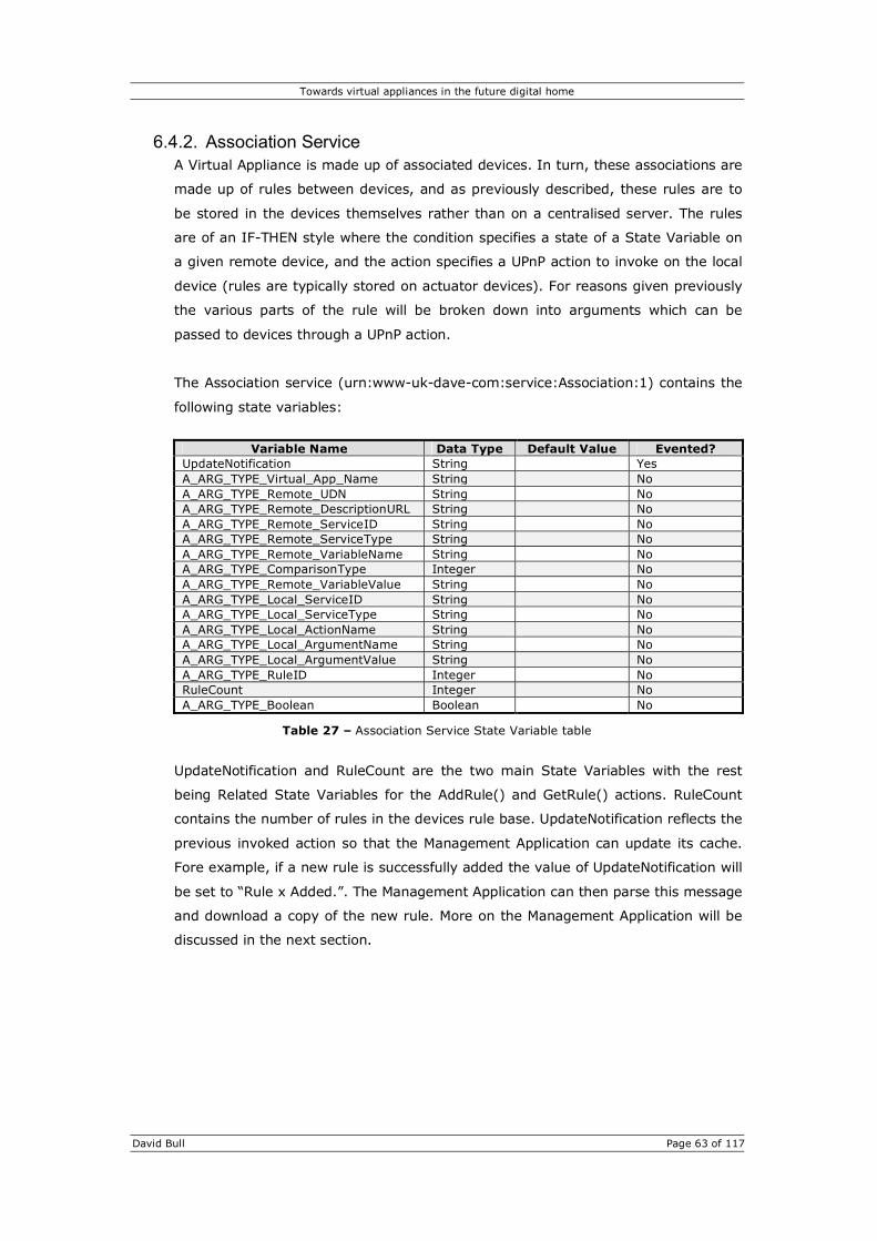
Towards virtual appliances in the future digital home
David Bull Page 63 of 117
6.4.2. Association Service A Virtual Appliance is made up of associated devices. In turn, these associations are
made up of rules between devices, and as previously described, these rules are to
be stored in the devices themselves rather than on a centralised server. The rules
are of an IF-THEN style where the condition specifies a state of a State Variable on
a given remote device, and the action specifies a UPnP action to invoke on the local
device (rules are typically stored on actuator devices). For reasons given previously
the various parts of the rule will be broken down into arguments which can be
passed to devices through a UPnP action.
The Association service (urn:www-uk-dave-com:service:Association:1) contains the
following state variables:
Variable Name Data Type Default Value Evented?
UpdateNotification String Yes A_ARG_TYPE_Virtual_App_Name String No A_ARG_TYPE_Remote_UDN String No A_ARG_TYPE_Remote_DescriptionURL String No A_ARG_TYPE_Remote_ServiceID String No A_ARG_TYPE_Remote_ServiceType String No A_ARG_TYPE_Remote_VariableName String No A_ARG_TYPE_ComparisonType Integer No A_ARG_TYPE_Remote_VariableValue String No A_ARG_TYPE_Local_ServiceID String No A_ARG_TYPE_Local_ServiceType String No A_ARG_TYPE_Local_ActionName String No A_ARG_TYPE_Local_ArgumentName String No A_ARG_TYPE_Local_ArgumentValue String No A_ARG_TYPE_RuleID Integer No RuleCount Integer No A_ARG_TYPE_Boolean Boolean No
Table 27 – Association Service State Variable table
UpdateNotification and RuleCount are the two main State Variables with the rest
being Related State Variables for the AddRule() and GetRule() actions. RuleCount
contains the number of rules in the devices rule base. UpdateNotification reflects the
previous invoked action so that the Management Application can update its cache.
Fore example, if a new rule is successfully added the value of UpdateNotification will
be set to “Rule x Added.”. The Management Application can then parse this message
and download a copy of the new rule. More on the Management Application will be
discussed in the next section.

Towards virtual appliances in the future digital home
David Bull Page 64 of 117
The Association service also defines the following actions:
Arguments Action Name
Name Direction Related State Variable VirtualAppName In A_ARG_TYPE_Virtual_App_Name RemoteUDN In A_ARG_TYPE_Remote_UDN RemoteDescriptionURL In A_ARG_TYPE_Remote_DescriptionURL RemoteServiceID In A_ARG_TYPE_Remote_ServiceID RemoteServiceType In A_ARG_TYPE_Remote_ServiceType RemoteVariableName In A_ARG_TYPE_Remote_VariableName ComparisonType In A_ARG_TYPE_ComparisonType RemoteVariableValue In A_ARG_TYPE_Remote_VariableValue LocalServiceID In A_ARG_TYPE_Local_ServiceID LocalServiceType In A_ARG_TYPE_Local_ServiceType LocalActionName In A_ARG_TYPE_Local_ActionName LocalArgumentName In A_ARG_TYPE_Local_ArgumentName LocalArgumentValue In A_ARG_TYPE_Local_ArgumentValue
AddRule
RuleID Out A_ARG_TYPE_RuleID RuleID In A_ARG_TYPE_RuleID VirtualAppName Out A_ARG_TYPE_Virtual_App_Name RemoteUDN Out A_ARG_TYPE_Remote_UDN RemoteDescriptionURL Out A_ARG_TYPE_Remote_DescriptionURL RemoteServiceID Out A_ARG_TYPE_Remote_ServiceID RemoteServiceType Out A_ARG_TYPE_Remote_ServiceType RemoteVariableName Out A_ARG_TYPE_Remote_VariableName ComparisonType Out A_ARG_TYPE_ComparisonType RemoteVariableValue Out A_ARG_TYPE_Remote_VariableValue LocalServiceID Out A_ARG_TYPE_Local_ServiceID LocalServiceType Out A_ARG_TYPE_Local_ServiceType LocalActionName Out A_ARG_TYPE_Local_ActionName LocalArgumentName Out A_ARG_TYPE_Local_ArgumentName
GetRule
LocalArgumentValue Out A_ARG_TYPE_Local_ArgumentValue GetRuleCount RuleCount Out RuleCount
RuleID In A_ARG_TYPE_RuleID DeleteRule Status Out A_ARG_TYPE_Boolean
ClearRules
Table 28 – Association Service Action table
AddRule allows rules to be added to the device’s rule base. The action takes 13
arguments which make up the rule. These arguments include information such as
the ID of the input/remote device, the URL to its XML description document, the ID
and type of the service as well as the name and value of the State Variable. The
value of the comparison type argument should be one of 1, 2 or 3 corresponding to
equals, less than or greater than, the service ID and type on the output/local
device, the action name and the name and value of one of the action’s arguments.
AddRule returns the ID of the new rule in the rule base, or a value of –1 if the rule
could not be added because it was invalid.
Passing a number to GetRule returns the corresponding rule from the rule base. If
the given rule ID does not exist in the device’s rule base then null is returned for all
output arguments.
DeleteRule is used to delete a rule from the device’s rule base and ClearRules
removes all rules from the device’s rule base

Towards virtual appliances in the future digital home
David Bull Page 65 of 117
When the UPnP AddRule method is invoked the rule is passed to the addRule()
method of the AssociationManager class in the form an instance of the Rule class.
This method checks the rule’s validity including checking both device’s services,
state variables and actions exist, and checks if an identical rule already exists. If the
rule is valid and unique then the AssociationManager, which comprises a UPnP
Control Point, subscribes to the input device’s service assuming there is not already
a subscription. The rule is also saved to disc and information about the input device
added to a UPnPDeviceStore (a class to simply store information about devices,
services and subscriptions).
Once the AssociationManager has subscribed to a device it will begin receiving
event notification from devices whenever one of their state variables changes. An
instance of the UPnPSubscriptionEventHandler is created for every subscription.
When an event notification is received the event is passed to the eventReceived()
method of the AssociationManager class. The eventReceived() method then
checks the ID of the device the rule came from, the service, the name of the state
variable and the value of the variable against all the condition halves of the rules in
the rule base. Any rule that matches is then placed in a queue. This queue is then
passed to a RuleMatchThread class which invokes each of the matching rules
actions in a separate thread allowing the AssociationManager to respond to the
remote device confirming receipt of the event notification before a timeout occurs.
If one of the remote devices goes offline then obviously part of the virtual appliance
will not function. When the device comes online again it announces itself to the
network. As the AssociationManager receives announcement messages from all
devices on the network it checks the device from which the announcement was
received against all devices listed in the condition half of all the rules in the rule
base. If there is a match the AssociationManager re-subscribes to the device’s
service(s).
Because the rule base is saved to disc then when the local device restarts the rule
base is loaded back into memory. The AssociationManager sends a search query
for all devices. All currently online devices will respond to this query and the
AssociationManager will re-subscribe to required devices in the manner described
above.
When rules are removed or the rule base is cleared the AssociationManager
unsubscribes from the services provided that there are no other rules requiring
them. This then prevents devices needlessly sending event notification over the
network.

Towards virtual appliances in the future digital home
David Bull Page 66 of 117
6.4.3. Rule Proxy Device As stated previously, other UPnP devices will obviously not implement the device
Association service so to remain compatible with those devices a service needs to be
created than can store and handle rules on behalf of other devices. This service
could be implemented in by another device as part of its regular services, or it could
be implemented in a device specifically designed for this task. The UPnP Rule Proxy
device takes the latter approach.
The UPnP Rule Proxy device implements only one service and does not provide any
sort of user interface other than that provided by the UPnP presentation page. The
Rule Proxy service (urn:www-uk-dave-com:service:RuleProxy:1) is very similar to
the regular Association service providing the same AddRule, GetRule, DeleteRule,
ClearRules and GetRuleCount actions.
The Rule Proxy service contains the following state variables:
Variable Name Data Type Default Value Evented?
UpdateNotification String Yes A_ARG_TYPE_Virtual_App_Name String No A_ARG_TYPE_Input_UDN String No A_ARG_TYPE_Input_DescriptionURL String No A_ARG_TYPE_Input_ServiceID String No A_ARG_TYPE_Input_ServiceType String No A_ARG_TYPE_Input_VariableName String No A_ARG_TYPE_ComparisonType Integer No A_ARG_TYPE_Input_VariableValue String No A_ARG_TYPE_Output_UDN String No A_ARG_TYPE_Output_DescriptionURL String No A_ARG_TYPE_Output_ServiceID String No A_ARG_TYPE_Output_ServiceType String No A_ARG_TYPE_Output_ActionName String No A_ARG_TYPE_Output_ArgumentName String No A_ARG_TYPE_Output_ArgumentValue String No A_ARG_TYPE_RuleID Integer No RuleCount Integer No A_ARG_TYPE_Boolean Boolean No
Table 29 – Rule Proxy Service State Variable table
The State Variables here are the same as the Association service except remote has
been changed to input and local has been changed to output. Two new State
Variables have also been added; A_ARG_TYPE_OutputUDN and
A_ARG_TYPE_Output_DescriptionURL. These are specific to the Rule Proxy as it
needs to know the ID of the output device along with the URL to its XML description
document.

Towards virtual appliances in the future digital home
David Bull Page 67 of 117
The Rule Proxy service also defines the following actions:
Arguments Action Name
Name Direction Related State Variable VirtualAppName In A_ARG_TYPE_Virtual_App_Name InputUDN In A_ARG_TYPE_Input_UDN InputDescriptionURL In A_ARG_TYPE_Input_DescriptionURL InputServiceID In A_ARG_TYPE_Input_ServiceID InputServiceType In A_ARG_TYPE_Inpput_ServiceType InputVariableName In A_ARG_TYPE_Input_VariableName ComparisonType In A_ARG_TYPE_ComparisonType InputVariableValue In A_ARG_TYPE_Input_VariableValue OutputUDN In A_ARG_TYPE_Output_UDN OutputDescriptionURL In A_ARG_TYPE_Output_DescriptionURL OutputServiceID In A_ARG_TYPE_Output_ServiceID OutputServiceType In A_ARG_TYPE_Output_ServiceType OutputActionName In A_ARG_TYPE_Output_ActionName OutputArgumentName In A_ARG_TYPE_Output_ArgumentName OutputArgumentValue In A_ARG_TYPE_Output_ArgumentValue
AddRule
RuleID Out A_ARG_TYPE_RuleID RuleID In A_ARG_TYPE_RuleID VirtualAppName Out A_ARG_TYPE_Virtual_App_Name InputUDN Out A_ARG_TYPE_Input_UDN InputDescriptionURL Out A_ARG_TYPE_Input_DescriptionURL InputServiceID Out A_ARG_TYPE_Input_ServiceID InputServiceType Out A_ARG_TYPE_Inpput_ServiceType InputVariableName Out A_ARG_TYPE_Input_VariableName ComparisonType Out A_ARG_TYPE_ComparisonType InputVariableValue Out A_ARG_TYPE_Input_VariableValue OutputUDN Out A_ARG_TYPE_Output_UDN OutputDescriptionURL Out A_ARG_TYPE_Output_DescriptionURL OutputServiceID Out A_ARG_TYPE_Output_ServiceID OutputServiceType Out A_ARG_TYPE_Output_ServiceType OutputActionName Out A_ARG_TYPE_Output_ActionName OutputArgumentName Out A_ARG_TYPE_Output_ArgumentName
GetRule
OutputArgumentValue Out A_ARG_TYPE_Output_ArgumentValue GetRuleCount RuleCount Out RuleCount
RuleID In A_ARG_TYPE_RuleID DeleteRule Status Out A_ARG_TYPE_Boolean
ClearRules
Table 30 – Rule Proxy Service Action table
Again, these are virtually identical to the actions provided by the Association service
with the exception that the AddRule and GetRule actions have two extra arguments
for the ID and description URL of the output device.
The Rule Proxy functions in very similar way to the Association service. It uses a
slightly modified version of the AssociationManager class called a RuleManager,
but the basic functionality is the same. Rules are stored in a ProxyRule class that
extends the regular Rule class to take into account the ID and description URL of
the output device.

Towards virtual appliances in the future digital home
David Bull Page 68 of 117
6.5. Management Servlet The Management Servlet is essentially a UPnP Control Point. The Control Point code is
contained in the UPnPControlPoint class while the Servlet code is contained in the
VirtualAppliancesServlet class.
When the Servlet is initialised it begins searching the network for any UPnP devices. As
devices are discovered and announced information about them and their services is
cached in an instance of the UPnPDeviceStore class (this is the same class used by
the Association service). If the device implements the Identification service then a
subscription is made and the name and location information cached. Likewise, if the
device implements the Association or RuleProxy services a subscription is added and
the rules downloaded and cached. These rules are stored in instances of the Rule and
ProxyRule classes and managed by an instance of the RuleManager class. As rules are
added and deleted from devices the UPnPControlPoint will receive notifications and
update the RuleManager accordingly.
The VirtualAppliancesServlet class is responsible for handling requests from clients
and returning the required XML documents. Documents and actions are specified by
passing parameters in the URL. For example, the URL
http://127.0.0.1:8080/upnp/upnp?page=devicelist
will result in the list of currently online devices being returned while
http://127.0.0.1:8080/upnp/upnp?page=virtualapps
will return a list of Virtual Appliances and their rules. Users will not have to worry about
these URLs or the XML documents as Cocoon will request these documents and
generate the HTML page.
VirtualApplianceServlet
UPnPControlPoint
UPnPDeviceStore RuleManager
Figure 22 - Class hierarchy for the Management Servlet

Towards virtual appliances in the future digital home
David Bull Page 69 of 117
The XML documents returned by the servlet are constructed based on the contents of
the cache of devices and rules. Examples of some of the XML documents can be found
in Appendix A.
The contents of the caches is only updated by event notifications from devices, so
when a rule is added to a device through the user interface the rule is not actually
added to the cache until an event notification is received from the device. This means
that the servlet does not have to perform any validity checking on arguments other
than to ensure the correct types and amounts are present.

Towards virtual appliances in the future digital home
David Bull Page 70 of 117
6.6. User Interface As mentioned previously Apache Cocoon is used to generate the user interface. It
does this by taking the XML output from the Management Servlet and applying
particular XSL stylesheets to generate an XHTML document (XHTML is a version of
HTML which conforms to XML rules and is compatible with all browsers). The
stylesheets used depend on the page being requested and the device the request
came from. The rules used to determine the transformations are contained in a
Cocoon Sitemap file.
To determine whether a request has come from a PC or a PDA the Cocoon sitemap
has been configured to check the client’s user-agent string. This is a string sent by
the web browser to the server as part of the HTTP request and serves the purpose of
identifying the browser. Cocoon can detect the type of client by matching sub-strings
of the user-agent string. Below is an extract from the sitemap file showing the sub-
strings used to identify PCs, PDAs and mobile phones.
<map:selectors default="browser"> <map:selector logger="sitemap.selector.browser" name="browser" src="org.apache.cocoon.selection.BrowserSelector"> <browser name="pc" useragent="MSIE 5"/> <browser name="pc" useragent="MSIE 6"/> <browser name="pc" useragent="Opera"/> <browser name="pc" useragent="Netscape/"/> <browser name="pc" useragent="Firebird"/> <browser name="pc" useragent="Gecko"/> <browser name="pda" useragent="MSPIE"/> <browser name="pda" useragent="Microsoft Pocket Internet Explorer"/> <browser name="pda" useragent="WinCE"/> <browser name="pda" useragent="Windows CE"/> <browser name="pda" useragent="PPC"/> <browser name="wap" useragent="Nokia"/> <browser name="wap" useragent="UP"/> <browser name="wap" useragent="Wapalizer"/> </map:selector> </map:selectors>
Although it was originally suggested that mobile phones might also be used to
manage the Virtual Appliances, it has become apparent after creating the PDA
stylesheets that displaying the required information on a mobile phone screen would
be very difficult. Also, although creating rules for Virtual Appliances is reasonably
simple from a PC and PDA, it would be extremely complicated from a mobile phone.
For these reasons no mobile phone stylesheets have been developed.
Sample XSL documents are included in Appendix B, and screenshots of the resulting
web pages are included in Appendix C.

Towards virtual appliances in the future digital home
David Bull Page 71 of 117
6.7. UPnP & SNAP Issues
6.7.1. UPnP Reliability During development of the UPnP devices a number of sporadic anomalies kept
recurring. Occasionally control points would seemingly miss announcements from
devices causing the device to either not appear online or be removed because its
lease expired. Similar problems seemingly randomly occurred with subscription
renewals being missed causing subscriptions to be removed and breaking the
virtual appliance. Another problem encountered affected the more complex UPnP
appliances which consisted of embedded devices. Sometimes the root device
would announce its presence but the embedded devices would not be announced.
A fair amount of time was spent examining these problems, but as no error
messages were ever produced and as the problems occurred randomly they could
not be re-produced. Also, I am aware of other people developing UPnP devices
with the Siemens stack who have reported similar experiences. Therefore it is
believed that the problem lies in the Siemens UPnP stack itself.
At the very beginning of this project the initial devices were created using the
older version of the UPnP stack, as used on the mDorm. During the course of
development a newer version of the stack was released and this seems to be much
more reliable, although problems do still occur from time to time.
6.7.2. SNAP Reliability Although the SNAP has more processing power and much memory than the TINI,
it is only just able to run two embedded UPnP devices. Any more than this and the
SNAP crashes due to lack of memory. In fact memory issues are still a problem
with just two devices. During development it was found that the SNAP would crash
if it was heavily accessed by UPnP control points. The problem appears to be that
the SNAP doesn’t invoke the Java Garbage Collector regularly enough to free up
memory to process all the requests. As such the memory runs out and the SNAP
crashes. A temporary solution has been to include a thread that regularly checks
the amount of free memory and if it falls below about 100k then it manually
invokes the garbage collector.
Earlier versions of the SNAP firmware were found to be very unreliable, with UPnP
devices lasting no more than 10-20 minutes before the board crashed. Newer
versions are much more stable but still exhibit problems.

Towards virtual appliances in the future digital home
David Bull Page 72 of 117
7. Project Management
7.1. Work Plan Appendix F contains the initial Gantt chart drawn up at the start of the project as well
as the actual Gantt chart. It is clear from these two charts that certain tasks differed in
the amount of time expected for completion. Also some tasks were delayed and some
started earlier. The idea for the project had come during the summer, before the start
of term. This and some similar work carried out as part of a student placement with BT
Exact allowed for work to commence immediately at the start of term.
The simple UPnP devices were created within three weeks, however these devices did
not contain any identification service or rule association service. Work on the Virtual
Appliance Management Application commenced earlier than planned because of the
lack of familiarity with XML, XSL and Apache Cocoon. The initial version of the
management application focused on creating the UPnP control point and getting it to
discover and maintain a record of devices on the network and then outputting this as
an XML document. XSL style sheets were then created for different client devices.
Work on the association service used to handle rules on the individual UPnP devices
started later than planned because of the research required to identify the best
solution, however the implementation still took the estimated time of six weeks. During
this time work on the management application continued.
Work on the XML and XSL documents for the management application took longer than
expected as each set of documents were created when required by the management
application. Initial versions of the management application simply returned a list of
devices, and so XML documents for listing virtual appliances were not designed until
later on. Most of the documents contain the same information about devices and so the
actual design of the individual documents did not take that long. The XSL style sheets
took longer than expected because of the complexity of some of the HTML and
JavaScript code required to create parts of the user interface.
As work on the simple UPnP devices has been finished relatively quickly, more complex
devices as well as devices based around a SNAP board were then created. As this was a
further objective it was not put on the initial project plan as they were only to be
created if everything else had been completed or was on target.

Towards virtual appliances in the future digital home
David Bull Page 73 of 117
7.2. Methodology Incremental prototyping was chosen as the software process for this project because,
unlike the Waterfall model, does not demand that the customer commit to set of
requirements before design begins, and it also allows functionality to be added in
stages. This process is also well suited to this project because of the nature of the
project being a concept demonstrator rather than a complete deliverable system.
As can be seen from the work plans and project diary (in the next section) the basic
UPnP devices were written first. At a latter stage the Identification service was
implemented and then finally the device association service. The management
application was also designed in a similar manner with extra functionality being added
once the previous build was proven to be correct. The XSL style sheets were also
designed and written in stages with the basic ones for the device list being created first
and the more complex one for rule creation being created later.
7.3. Project Diary
7.3.1. Week 1 Downloaded a number of papers from the Essex CC464 course area [20] and
started creating a simple UPnP light bulb.
7.3.2. Week 2 Reading through papers and conducting more research. On the devices front the
UPnP light bulb is fully functional and a UPnP switch has also been created.
7.3.3. Week 3 Created another two UPnP devices; a motion sensor and a timer. Also wrote and
submitted the initial proposal of the project.
7.3.4. Week 4 All of the basic simulated UPnP devices are now created and fully functional
although they cannot yet be linked. In order to distinguish between numerous
devices of the same time an Identification service has been written which all the
devices now implement allowing the user to specify a name and location for the
device. Also ordered a book on XML as well as playing with some tutorials found on
the Internet.
7.3.5. Week 5 Started creating the UPnP Control Point that will form the Management Application
and made a start writing the Project Plan & Progress Report document.

Towards virtual appliances in the future digital home
David Bull Page 74 of 117
7.3.6. Week 6 Spent all week finishing off the Project Plan & Progress Report ready for handing in
next week. Managed to do a bit more work on the Management Application so that
it now outputs a list of UPnP devices in XML.
7.3.7. Week 7 Set Cocoon up and created an XSL stylesheet to take the XML list of UPnP devices
and transform it into a basic HTML page.
7.3.8. Week 8 Did a bit more work on the Management Application. Played around with Cocoon to
try and get it configured properly and created some more complex XSL stylesheets.
7.3.9. Week 9 No project work this week because of other assignments.
7.3.10. Week 10 No project work this week because of other assignments.
7.3.11. Week 11 No project work this week because of other assignments.
7.3.12. Week 12 Made a start designing an association service to run on the UPnP devices to allow
them to be linked.
7.3.13. Week 13 Got the basis of an association service working, still more work to do on it though.
7.3.14. Week 14 Association service seems to be working. Devices can be associated by manually
sending rules using the Siemens User Control Point. Was able to get a switch to
control a light bulb by putting a rule on the light.
7.3.15. Week 15 Did lots of work on the management appliance. It now downloads and caches rules
from devices and can return an XML document with a list of devices and the rules
they contain. Also wrote some more XSL stylesheets and started creating a proper
HTML layout for the user interface.
7.3.16. Week 16 Ironed out a few bugs in the association service. The management application and
XSL stylesheets are coming along nicely.

Towards virtual appliances in the future digital home
David Bull Page 75 of 117
7.3.17. Week 17 Working on the XSL stylesheets and HTML layout of the user interface. Also
collected an mDorm (contains a SNAP board) so that some of the sensors and
actuators can be UPnP enabled to make the project seem that bit more “real”.
7.3.18. Week 18 Spent this week playing with the mDorm and working out what its capabilities are in
terms of the number of UPnP devices it can support with its rather limited amount of
memory. Turned out that 2 devices are about the limit. Also a bug was found in the
java.net.URL class on the SNAP. Emailed Imsys about this who confirmed the bug
and said they’d fix it in the next release.
7.3.19. Week 19 Got a UPnP Temperature Sensor and Light Sensor working on the mDorm. Did some
more work on the management application so that it now shows the Virtual
Appliances as separate page from the one showing devices with their rules. Also
created a UPnP camera using a webcam and the Java Media Framework.
7.3.20. Week 20 Finished of the XSL stylesheets for the PC. Started creating some complex UPnP
appliances, the first one being a UPnP Internet Radio that uses JavaLayer to stream
audio from various Shoutcast servers. Also created the XSL stylesheets for the PDA.
7.3.21. Week 21 Created and submitted the report outline and made a start on the actual report.
Also created a UPnP Audio/Video playback device.
7.3.22. Week 22 All the UPnP devices are completed and the management application appears to be
complete. Now it’s just testing and bug fixing. Also did some more work on the
project report.
7.3.23. Week 23 More work on the project report.
7.3.24. Week 24 More work on the project report. Discovered that a new version of the SNAP
firmware has been released (0.16.0rc2) which, among others, has fixed the bug
with java.net.URL found 5 weeks ago. Also Paul and Rowan from BT Exact came
round to test the completed system and give their feedback and comments.
7.3.25. Week 25 Report completed, bound and submitted.

Towards virtual appliances in the future digital home
David Bull Page 76 of 117
7.4. Evaluation of Project Management The work flow chart drawn up the beginning of the project proved to be very useful in
keeping the project on track as it would have been very easy to get carried away with
particular parts of the system and run out of time whilst working on others. Despite the
rather large difference between the initial and actual Gantt charts the main objectives
of the project were completed well within time which allowed the further objectives to
also be completed.
The use of the incremental prototyping process was also useful as it allowed the basic
devices to be written first with more functionality being added latter. The same applies
to the management application and the XSL stylesheets.

Towards virtual appliances in the future digital home
David Bull Page 77 of 117
8. Testing & Evaluation
8.1. Testing
8.1.1. Introduction The system consists of a large number of components; individual UPnP devices as
well as the management servlet and the XSL stylesheets for Cocoon. A number of
the UPnP devices also share common services such as the Identification and
Association services. Each of these components must be tested in isolation against
pre-defined test cases. Once each component has been tested and any bugs fixed
the system should be tested again to ensure the bug fixes didn’t themselves
introduce any new defects. Once all the components have been successfully tested
the system can be tested as a whole using integration testing. During all testing
procedures the components as well as the overall system will be treated as a black-
box (functional testing).
Also, as this project is demonstrating a new concept user feedback is very
important. This feedback can be used to gauge the usefulness of the concept and
what changes would need to be made if this concept were to be developed further.
8.1.2. Component Testing As described above each UPnP device will be individually tested using component
testing and treated as a black-box. The results of the component test are shown in
Appendix E. Some devices share common services and in these instances the
service will only been tested once.
8.1.3. Integration Testing & User Feedback Once the individual UPnP devices have been tested the overall system can then be
tested. This involves running numerous UPnP devices and then creating and
managing Virtual Appliances through the user interface using a PC and PDA. As well
as testing the system for defects a number of people will be asked to perform
various tasks and asked to give their feedback on the system.

Towards virtual appliances in the future digital home
David Bull Page 78 of 117
8.2. Evaluation For this project a number of UPnP devices, both simulated and real, have been
developed. Some of these devices are relatively simple, such as the switch and light
bulb, and some are simulations of more complex appliances such as the Internet Radio
and Audio/Video appliance. All the program code has been written using Java which
allows the devices to run on both Windows and Linux. Even the UPnP mDorm device
that runs on the SNAP board is written in Java and if it were not for access to specific
hardware sensors, the same code could run on a PC without modification.
The use of the Siemens Java UPnP Stack provided a platform independent mechanism
for automatic service discovery and utilisation. As with Jini, because the Java version of
the UPnP stack was used no provision is made for automatic network configuration.
Instead it is assumed that the device itself will be able to configure its network
interface. In terms of PCs, the operating system can be configured to use a DHCP
server, or to use statically assigned IP addresses. If Windows is configured to use a
DHCP server and one is not present then it will automatically use link-local addressing,
the same is probably true of Linux as well. However the SNAP board must either be
assigned a static IP address manually, or use a DHCP server. It is important to note
though that the UPnP specification places no requirements on their being any kind of
network infrastructure already in place.
The system was designed to be resilient against temporary failure of devices. For
example, if a UPnP switch and light bulb are associated, then if, say, the switch is
removed from the network and then started with a different IP address the light bulb
will detect this and re-subscribe to the switch. This will work provided the switch
announces to the network that it is going offline. If it doesn’t then when it comes back
online the light bulb will have no idea the switch disappeared and will still believe it is
subscribed. To resolve this the device would have to send a “bye-bye” message when it
starts up and before it announces its presence.
Another requirement of the system was it be as decentralised as possible. This has
been achieved by storing the rules used to build Virtual Appliances on the actual
devices rather than on a central server. Devices then subscribe to the services required
by the rules and receive event notifications when evented state variables are updated.
The state change is then checked against all the rules in the devices rule base and the
associated action of matching rules is fired.

Towards virtual appliances in the future digital home
David Bull Page 79 of 117
A user interface provides a way for users to create and manage the virtual appliances.
The user interface meets the requirements listed in Section 3.1 by providing a list of
devices currently on the network, technical details for each device, a list of the virtual
appliances created and the rule they are made up of, and a mechanism for the user to
create and edit virtual appliances. The interface has also been designed in such a way
that it is automatically tailored to the display capabilities of the client. Currently PCs
and PDAs are supported. Support for mobile phones was not implemented because the
size of the display would make it extremely difficult to show the required information
for the user to manage the virtual appliances in a user-friendly manner.
8.2.1. User Feedback Although the system has been proven to work and met the requirements listed in
Section 3, the usefulness of the Virtual Appliances still needs to be determined. In
order to determine this usefulness and receive general feedback on what users
thought of the system a number of people were asked to play with the system and
give their comments.
Whilst in a commercial environment the capturing of user feedback would involve
the use of formal methods and a large number of subjects, the resource limitations
and time constraints imposed on this project have lead to a more limited evaluation.
However, from the user feedback given below it is clear that even a small-scale
evaluation can be helpful.
The user feedback obtained is shown below.
• The pages where you select the input and output devices for constructing rules
may get confusing if lots of devices are present. Would it be possible to show a
list of devices that are better suited for linking with the previous device?
• With the device identification it would be good to have a list of previously used
locations and possibly a pre-defined list otherwise one person may say a
device is located in a lounge, and another may say it is located in the living
room. This would then enable the user to sort devices by their location in the
situation where lots of devices are present.
• The rules used are simple but do work well. Maybe the next version will use
Boolean logic (although it gets difficult to design). You might even end up
writing your own language to define rules!
• Getting normal people to create the rules will always be problem

Towards virtual appliances in the future digital home
David Bull Page 80 of 117
• Virtual appliance “templates” could be used to allow a number of basic
appliances, such an alarm clock, to be constructed. An alarm clock typically
consists of a clock service and a device that can make a noise. So a user could
choose to create an alarm clock and all they have to do is select the time and
where the noise should be made. The interface then automatically generates
the rules and locates an available clock service.
• Love the idea of distributing the rules, how about caching the rules elsewhere
for backup and protection against failure? You could have a number of Rule
Proxies that keep copies of all the rules on the network for backup so they not
actually fired, but if a device forgets its rules they can be automatically re-sent
back to the device from the cache.
• You could do with more “real” UPnP devices. How about wrapping some X10
devices in UPnP?

Towards virtual appliances in the future digital home
David Bull Page 81 of 117
9. Conclusion
9.1. Summary of Main Achievements This project has succeeded in demonstrating the concept of creating and managing
Virtual Appliances. It has shown the concept of de-composing modern-day appliances,
the concept of service discovery, and the concept of re-composition to create new
virtual appliances.
One of the main achievements of the system is the distribution of rules. The distributed
nature of the system appears to be fairly unique as most other systems take a more
centralised approach, such as the iDorm.
The user interface is also another main achievement in terms of how the interface is
adapted to the display capabilities of the client. The use of XSL to transform the XML
allows new stylesheets to be created for new devices without any modification to the
management servlet. XSL also allows XML documents to be transformed into other
types of files and documents, such as SpeechML which would be suitable for blind
users. Special versions of the interface could be made for partially sighted users where
large fonts and highly contrasting colours are used.
Another feature of the user interface is the context-sensitivity of the options used in
creating rules. When creating rules the user has to pick the devices, services, state
variables and actions. Once the input and output devices are selected the services,
state variables and actions are selected through drop down menus. As different
services are selected the drop down menus containing state variables and actions are
updated. Inappropriate state variables and actions are not shown in an effort to aid the
user in designing the rule.

Towards virtual appliances in the future digital home
David Bull Page 82 of 117
9.2. Extensions and Further Work Because of time limitations difficult decisions had to be made about which ideas to
implement and how much time should be spent on them. However, the priorities and
choices made in this project have allowed a basic demonstration of the concept to be
created. Whilst this project has successfully demonstrated the concept of
de-composing and re-composing appliances to build virtual appliances there are a
number of extensions and further work that could be carried out.
One important extension would be to re-design the rules used to associate devices. The
current rules were kept fairly basic to ease parsing on low-spec hardware and to keep
the user interface as simple as possible for creating these rules. However these rules,
while allowing a large number of virtual appliances to be constructed, were also quite
limiting. For example, there is currently no ELSE clause, and Boolean operators such as
AND and OR are not implemented. Adding these features would then allow rules such
as “IF light_level < 30 AND motion = 1 THEN light.power = on ELSE
light.power = off” to be created, which are currently impossible.
With these improved and more complex rules the design of the user interface, through
which the user actually creates the rules, would have to be carefully designed in order
to be as user-friendly as possible and display properly on a range of devices. The idea
of providing templates for virtual appliances was mentioned in user feedback and could
prove an effective way of aiding users in creating basic virtual appliances without being
exposing them to the underlying rules. An important consideration when re-designing
the user interface would be to not constrain the user in any way in terms of the virtual
appliances they can build, but whilst ensuring that they can only create valid
configurations. The whole concept of virtual appliances is about empowering the user
to associate devices in ways the designers themselves may not even have thought of.
The system implemented here does not currently have a notion of self-healing,
although it is resilient to temporary device failure. Further extensions should allow a
virtual appliance to automatically adapt to use the same service provided by a different
device when one it is currently using disappears. This implies some form of heart-beat
to determine when a device has gone offline. Currently the only way to detect whether
a device goes offline is if it announces to the network that it is leaving, or when its
advertisement expires. These leases are typically 30 minutes long. Also, as mentioned
previously, if a device goes offline without announcing the fact, and then comes back
online before its lease would expire, subscribed devices will be unaware of the outage
and still believe they are subscribed. In some situations though, self-healing may be
difficult such as when a required light disappears. However, with something like a timer
service the location of that service is unimportant.

Towards virtual appliances in the future digital home
David Bull Page 83 of 117
Another aspect to this self-healing and resilience to failure is that of backing up rules,
as mentioned in the user feedback. A scenario where this would be required is where a
device fails and has to be replaced. This new device would not only have a different
network ID, but also have no knowledge of the rules used by its predecessor. In this
situation the system should detect the new device and send a copy if the rules to the
device so that it can immediately take over the role of the previous device without any
user interaction.
Also, the issues of security, access control and resource allocation have not been
addressed in this project. The next version of UPnP, currently being drafted, is
expected to address security and access control issues. In the current system it is quite
possible to accidentally (or deliberately) create two or more virtual appliances to try
and access a single device at the same time, for example a timer or light. This also
leads on to detection of rule conflicts, which is made all the more difficult by the use of
a distributed rule set rather than having all the rules stored in one place. Also, different
classes of rules and appliances could be defined, such as safety, efficiency and comfort.
Each of these classes then has a priority and, for example, a rule or virtual appliance
could then not be added to the system if it compromises safety.
One important finding during the development of the UPnP mDorm device was that
although the SNAP is designed for constructing sensor networks, it is sadly not quite
powerful enough to run UPnP. Use of a MiniITX, or the even newer NanoITX, system
may be a better option for constructing UPnP enabled sensor networks. Another
observations is that although Cocoon provided a very good mechanism for
automatically generating a user interface based upon client’s display capabilities, it is
probably a bit to heavy-weight for the requirements of this project, although its use
here meant that an alternative solution did not have to be developed.
9.3. The Future… The long-term goal of this vision is that of ambient intelligence in environments so that
they can respond to the needs and desires of occupants. However to achieve this
computing and networking technology must first disappear into everyday artefacts
around the home. This project has attempted to lay the technological groundwork for
such an environment.

Towards virtual appliances in the future digital home
David Bull Page 84 of 117
10. References & Bibliography
10.1. References Figure 1: Image of VCR Accessed: 2nd November 2003 http://ag.arizona.edu/ecat/multimedia/vcr.gif Figure 2: The iDorm Accessed: 2nd March 2004 http://iieg.essex.ac.uk/images/idorm200.gif Figure 3: The networks used in the iDorm Accessed: 2nd March 2004 http://cscourse.essex.ac.uk/course/cc464/courseware/papers/EssexPapers/SX CCGrid 2002.pdf Figure 4: UPnP in the iDorm Accessed: 6th March 2004 http://cscourse.essex.ac.uk/course/cc464/courseware/movies/iDorm UPnP.wmv Figure 5: The IBM Meta Pad handheld with touch-screen next to a Meta Pad core. Accessed: 13th March 2004 http://www.computerworld.com/computerworld/records/images/story/IBM_metapad2_secondary.jpg Figure 6: Image of TINI board Accessed: 24th February 2004 http://www.ibutton.com/TINI/images/tiniboard.jpg Figure 7: iButton Accessed: 24th February 2004 http://www.ibutton.com/products/images/genericibutton.jpg Figure 8: Image of SNAP board Accessed: 5th November 2003 http://www.apms.com.au/tini/tini-back.jpg Figure 9: The Cjip microprocessor Accessed: 24th February 2004 http://www.imsys.se/images/cjip.jpg Figure 10: A PC/104 stack Accessed: 24th February 2004 http://www.controlled.com/pc104faq/pc104stack.jpg Figure 11: VIA EPIA M10000 Mini-ITX Motherboard Accessed: 24th February 2004 http://www.via.com.tw/en/images/Products/VInternet/M10000_3_L.jpg Figure 12: UPnP devices in the digital home Accessed: 25th February 2004 http://www.intel.com/update/images/it06031_g2.gif Figure 15: The Salutation architecture Accessed: 26th February 2004 http://www.salutation.org/spec/Sa20e1a21.pdf

Towards virtual appliances in the future digital home
David Bull Page 85 of 117
Figure 16: The use of Service and Description Records Accessed: 26th February 2004 http://www.salutation.org/spec/Sa20e1a21.pdf [1] EEE111A/B Microprocessors
Accessed: 23rd February 2004 http://www.engj.ulst.ac.uk/sidk/eee111a/eee111_1.pdf
[2] Smart Environments booklet Accessed: 2nd March 2004 http://machen.mrl.nott.ac.uk/PublicationStore/Smart_Environments_booklet.pdf
[3] AutoHAN Core Services White Paper One Accessed: 2nd March 2004 http://www.cl.cam.ac.uk/Research/SRG/HAN/AutoHAN/autohan/autohan_paper1.html
[4] AutoHAN Project Proposal Accessed: 2nd March 2004 http://www.cl.cam.ac.uk/Research/SRG/HAN/AutoHAN/docs/proposal.html
[5] TINI: Introducing TINI Accessed: 24th February 2004 http://www.ibutton.com/TINI/
[6] Application Note 195 DSTINI1 (TINIm390) Verification Module Chipset Reference Design Accessed: 24th February 2004 http://pdfserv.maxim-ic.com/en/an/app195.pdf
[7] iButton: 1-Wire Weather Station Accessed: 24th February 2004 http://www.ibutton.com/weather/index.html
[8] SNAP: Simple Network Application Platform Accessed: 24th February 2004 http://www.imsys.se/docs/snap_flyer.pdf
[9] Imsys: The Cjip Processor Accessed: 24th February 2004 http://www.imsys.se/products/prodcjip.shtml
[10] PC/104 Embedded Systems FAQ Accessed: 24th February 2004 http://www.controlled.com/pc104faq/
[11] PC104.COM – What is PC104? Accessed: 24th February 2004 http://www.pc104.com/whatis.html
[12] mini-itx.com - faq Accessed: 24th February 2004 http://www.mini-itx.com/faq.asp
[13] Technology Brief – Mac OS X: Rendezvous Accessed: 25th February 2004 http://a144.g.akamai.net/7/144/51/c85db1658520b0/www.apple.com/macosx/pdf/Panther_Rendezvous_TB_10232003.pdf

Towards virtual appliances in the future digital home
David Bull Page 86 of 117
[14] UPnP Forum Accessed: 25th February 2004 http://www.upnp.org/
[15] Intel Corporation – UPnP Technology Overview Accessed: 25th February 2004 http://www.intel.com/technology/UPnP/tech.htm
[16] UPnP – The Foundation of the Digital Home Accessed: 25th February 2004 http://www.intel.com/update/contents/it06031.htm
[17] Salutation – Frequently Asked Questions Accessed: 26th February 2004 http://www.salutation.org/faqs.htm
[18] Salutation Specification V2.0c Part 1 Accessed: 26th February 2004 http://www.salutation.org/spec/Sa20e1a21.pdf
[19] Jini Technology Architectural Overview Accessed: 26th February 2004 http://wwws.sun.com/software/jini/whitepapers/architecture.html
[20] CC464 – Pervasive Computing and Ambient Intelligence Accessed: 6th March 2004 http://cscourse.essex.ac.uk/course/cc464/
[21] Java MP3 Player Accessed: 7th March 2004 http://www.javazoom.net/javalayer/javalayer.html
[22] Antelope Technologies – Vision for Modular Computing Accessed: 13th March 2004 http://www.antelopetech.com/en/index.aspx?view=i-products_theVision.htm
[23] IBM Think Research | The Amazing Shrinking Computer Accessed: 13th March 2004 http://www.research.ibm.com/thinkresearch/pages/2002/20020207_metapad.shtml
[24] A. Pounds-Cornish, A. Holmes (2002), The iDorm – a Practical Deployment of Grid Technology, In 2nd IEEE International Symposium on Cluster Computing and the Grid (CCGrid2002)

Towards virtual appliances in the future digital home
David Bull Page 87 of 117
10.1.1. Images and Icons The images and icons used by the UPnP devices in this project were found through Google Images and are referenced below. UPnP Light Bulb Icon: http://www.maubi.net/~waterson/blog/light-bulb.gif UPnP Light Bulb: http://www.bcec.com/images/bulboff.gif UPnP Light Switch Icon: http://www.thepocket.com/lightswitchic.jpg UPnP Motion Sensor Icon: http://www.faw.uni-freiburg.de/dekanat/images/walk.gif UPnP Motion Sensor: http://www.habitek.co.uk/Habitek2001EC/cat1445.gif UPnP Timer: http://npin.org/library/pre1998/n00272/n00272images/clock.gif UPnP Camera Icon: http://user.it.uu.se/~leom/images/webcam.gif UPnP Radio Icon: http://www.fandango.co.jp/oshaberi/img/radio_icon_anime.gif UPnP Radio Tuner Icon: http://www.talespin.com/images/knobIcon3.gif UPnP Radio LCD Icon: http://www.saitek.co.uk/chess/images/featicons/lcd.gif UPnP Radio Clock Icon (large): http://www.orl.arch.ethz.ch/dl/Chicago/logos/clock.gif UPnP Radio Clock Icon (small): http://ns.fcs.ucr.ac.cr/~historia/mod-cole/clock.gif UPnP Radio Audio Icon: http://www.powerspec.com/support/tech_notes/images/speaker_icon.gif UPnP A/V Device Icon: http://www.lrz-muenchen.de/services/arbeitsplatzsysteme/mm-labor/mm.gif UPnP A/V Video Icon (large): http://www.sharksearch.com/images/icon-film.gif UPnP A/V Video Icon (small): http://jchemed.chem.wisc.edu/JCESoft/CCA/CCA1/GRAPHICS/movicon.gif UPnP mDorm Icon: http://www.iconarchive.com/icon/sci-fi/startrekships_by_iconfactory/Borg.gif UPnP mDorm Temperature Icon: http://vtv.battanet.hu/kepek/idojaras/thermometer.gif
10.2. Bibliography • UPnP, Jini and Salutation – A look at some popular co-ordination frameworks for
future networked devices. Accessed: 25th February 2004 http://www.cswl.com/whiteppr/tech/upnp.html
• Introducing Cocoon Accessed: 3rd March 2004 http://cocoon.apache.org/2.1/introduction.html
• M. Morrison (2002), SAMS Teach Yourself XML in 24 Hours Second Edition, Sams Publishing, ISBN: 0-672-32213-7

Towards virtual appliances in the future digital home
David Bull Page 88 of 117
Appendices

Towards virtual appliances in the future digital home
David Bull Page 89 of 117
Appendix A. XML Documents for the Management Application
1. XML Document for Device List
<devices> <device> <UDN>uuid:af688879-b94f-4d96-9da0-f11e99f167d8</UDN> <rootDevice>true</rootDevice> <parentDeviceUDN/> <deviceType>urn:www-uk-dave-com:device:LightBulb:1</deviceType> <friendlyName>Light Bulb</friendlyName> <icon>http://10.0.0.20:8081/icon.gif</icon> <smallicon>http://10.0.0.20:8081/favicon.gif</smallicon> <descriptionURL> http://10.0.0.20:8081/af688879-b94f-4d96-9da0- f11e99f167d8/description.xml </descriptionURL> <identification> <name/> <location>PC</location> </identification> </device> <device> <UDN>uuid:d9428667-0379-4c44-b6a4-f27977ed004b</UDN> <rootDevice>true</rootDevice> <parentDeviceUDN/> <deviceType>urn:www-uk-dave-com:device:Switch:1</deviceType> <friendlyName>Switch</friendlyName> <icon>http://10.0.0.20:8082/icon.gif</icon> <smallicon>http://10.0.0.20:8082/favicon.gif</smallicon> <descriptionURL> http://10.0.0.20:8082/d9428667-0379-4c44-b6a4- f27977ed004b/description.xml </descriptionURL> <identification> <name/> <location>PC</location> </identification> </device> </devices>

Towards virtual appliances in the future digital home
David Bull Page 90 of 117
2. XML Document for Virtual Appliances <virtualAppliances> <virtualAppliance> <name>Light Switch</name> <rules> <rule id="0"> <ruleOwnerUDN>uuid:af688879-b94f-4d96-9da0-f11e99f167d8</ruleOwnerUDN> <ruleOwnerRuleID>0</ruleOwnerRuleID> <inputUDN>uuid:d9428667-0379-4c44-b6a4-f27977ed004b</inputUDN> <inputDeviceIcon>://10.0.0.20:8084/icon.gif</inputDeviceIcon> <inputDeviceSmallIcon> http://10.0.0.20:8084/favicon.gif </inputDeviceSmallIcon> <inputFriendlyName>Switch</inputFriendlyName> <inputServiceID>urn:www-uk-dave-com:serviceId:Switch</inputServiceID> <inputServiceType> urn:www-uk-dave-com:service:Switch:1 </inputServiceType> <inputServiceName>Switch</inputServiceName> <inputVariableName>State</inputVariableName> <comparisonType>1</comparisonType> <inputVariableValue>*</inputVariableValue> <outputUDN>uuid:af688879-b94f-4d96-9da0-f11e99f167d8</outputUDN> <outputDeviceIcon>http://10.0.0.20:8082/icon.gif</outputDeviceIcon> <outputDeviceSmallIcon> http://10.0.0.20:8082/favicon.gif </outputDeviceSmallIcon> <outputFriendlyName>Light Bulb</outputFriendlyName> <outputServiceID>urn:www-uk-dave-com:serviceId:Power</outputServiceID> <outputServiceType> urn:www-uk-dave-com:service:Power:1 </outputServiceType> <outputServiceName>Power</outputServiceName> <outputActionName>TogglePower</outputActionName> <outputArgumentName>null</outputArgumentName> <outputArgumentValue>null</outputArgumentValue> </rule> </rules> </virtualAppliance> </virtualAppliances>

Towards virtual appliances in the future digital home
David Bull Page 91 of 117
Appendix B. XSL Documents for User Interface
3. XSL Document for Device List on PC <?xml version="1.0"?> <xsl:stylesheet version="1.0" xmlns:xsl="http://www.w3.org/1999/XSL/Transform"> <xsl:template match="/"> <html> <head> <title>Virtual Appliances - Device List</title> <link rel="stylesheet" type="text/css" href="main.css"/> <link rel="shortcut icon" href="favicon.ico"/> <script language='JavaScript'> function popUp(page) { popUpWin = window.open(page,'winPopUp','resizeable=no,scrollbars=no,width=700,height=700'); } function rescan() { var response = confirm("WARNING: This will erase all cached devices and rules and rescan the network. It could take up to a couple of minutes to re-detect all devices and rules. Are you sure you wish to continue?"); if (response) document.rescanForm.submit(); } </script> </head> <body> <div id="title"> <h1>Virtual Appliances</h1> <div class="iebugfix"> <img src="/images/pixel.gif" width="1" height="1"/> </div> </div> <div id="nav"> <h1>Menu</h1> <ul> <li><a href="index.html?page=devicelist">Device List</a></li> <li><a href="index.html?page=devicerules">Device Rules</a></li> <li><a href="index.html?page=virtualapps">Virtual Appliances</a></li> </ul> <ul> <li><a href="javascript:rescan();">Rescan Network</a></li> </ul> <form name="rescanForm" action="./index.html" method="POST"> <input type="hidden" name="page" value="rescan"/> </form> </div> <div id="main"> <h1>Device List</h1> <div id="body"> <p> There are currently <xsl:value-of select="count(devices/device)"/> UPnP devices present on the network: </p>

Towards virtual appliances in the future digital home
David Bull Page 92 of 117
<blockquote> <table border="0" cellspacing="20"> <xsl:for-each select="devices/device"> <xsl:if test="position() mod 4 = 1"> <tr> <xsl:apply-templates select="."/> <xsl:apply-templates select="following-sibling::device[position()=1]"/> <xsl:apply-templates select="following-sibling::device[position()=2]"/> <xsl:apply-templates select="following-sibling::device[position()=3]"/> </tr> </xsl:if> </xsl:for-each> </table> </blockquote> </div> <div class="iebugfix"> <img src="/images/pixel.gif" width="1" height="1"/> </div> </div> </body> </html> </xsl:template> <xsl:template match="device"> <xsl:variable name="UDN" select="./UDN"/> <xsl:variable name="iconurl" select="./icon[.!='']"/> <xsl:variable name="friendlyName" select="./friendlyName"/> <td width="150" align="center" valign="top"> <div class="deviceCell"> <table border="1" cellpadding="5"><tr><td align="center" valign="top"> <a href="javascript:popUp('index.html?page=deviceinfo&udn={$UDN}')"><xsl:if test="boolean($iconurl)"><img src="{$iconurl}"/></xsl:if><xsl:if test="not(boolean($iconurl))"><img src="no-image.gif"/></xsl:if></a> </td></tr></table> <a href="javascript:popUp('index.html?page=deviceinfo&udn={$UDN}')"><small><xsl:copy-of select="$friendlyName"/></small></a><br/> <xsl:if test="identification/name!='' or identification/location!=''"> <small>(<xsl:if test="identification/name!=''"><xsl:value-of select="identification/name"/></xsl:if><xsl:if test="identification/name!='' and identification/location!=''">, </xsl:if><xsl:if test="identification/location!=''"><xsl:value-of select="identification/location"/></xsl:if>)</small> </xsl:if> </div> </td> </xsl:template> </xsl:stylesheet>

Towards virtual appliances in the future digital home
David Bull Page 93 of 117
4. XSL Document for Device List on PDA <?xml version="1.0"?> <xsl:stylesheet version="1.0" xmlns:xsl="http://www.w3.org/1999/XSL/Transform"> <xsl:template match="/"> <html> <head> <title>Virtual Appliances - Device List</title> </head> <body> <center> <font size="5"><b>Virtual Appliances</b></font><br/> <font size="1">[ <a href="index.html?page=devicelist">Device List</a> | <a href="index.html?page=virtualapps">Virtual Appliances</a> ]</font> <hr/> </center> <p><font size="3"><b>Device List</b></font></p> <p><font size="1">There are currently <xsl:value-of select="count(devices/device)"/> UPnP devices present on the network:</font></p> <ul> <xsl:for-each select="devices/device"> <xsl:variable name="UDN" select="./UDN"/> <xsl:variable name="friendlyName" select="friendlyName"/> <xsl:variable name="smallIconURL" select="smallicon"/> <li> <font size="1"> <a href="index.html?page=deviceinfo&udn={$UDN}"><xsl:if test="boolean($smallIconURL)"><img src="{$smallIconURL}" width="16" height="16" border="0" alt="{$friendlyName}"/> </xsl:if><xsl:value-of select="friendlyName"/></a> <xsl:if test="identification/name!='' or identification/location!=''">  (<xsl:if test="identification/name!=''"><xsl:value-of select="identification/name"/></xsl:if><xsl:if test="identification/name!='' and identification/location!=''">, </xsl:if><xsl:if test="identification/location!=''"><xsl:value-of select="identification/location"/></xsl:if>) </xsl:if> </font> </li> </xsl:for-each> </ul> </body> </html> </xsl:template> </xsl:stylesheet>

Towards virtual appliances in the future digital home
David Bull Page 94 of 117
Appendix C. Screenshots of the User Interface
1. PC – Device List

Towards virtual appliances in the future digital home
David Bull Page 95 of 117
2. PC – Virtual Appliances

Towards virtual appliances in the future digital home
David Bull Page 96 of 117
3. PC – Device Rules

Towards virtual appliances in the future digital home
David Bull Page 97 of 117
4. PC – Creating a Virtual Appliance

Towards virtual appliances in the future digital home
David Bull Page 98 of 117
5. PDA – Device List & Virtual Appliances

Towards virtual appliances in the future digital home
David Bull Page 99 of 117
Appendix D. Modified mDorm Java Class import java.util.*; import com.dalsemi.onewire.*; import com.dalsemi.onewire.adapter.*; import com.dalsemi.onewire.container.*; import com.dalsemi.system.DataPort; import com.dalsemi.system.IllegalAddressException; /** * This class is based on the mDorm class written by A. Pounds-Cornish, A. Holmes, * F. Rivera-Illingworth at the University of Essex. It has been modified to include only those methods * required by my program and it has also been optimised to use memory more efficiently. * In fact, during testing my version was 2.64 times more memory efficient and 1.72 times faster. * * @author David Bull * @version 1.0, 02/02/04 */ public class MyMdorm { //////////////////////////////////////////////////// // CONSTANTS AND CLASS VARIABLES //////////////////////////////////////////////////// private static final byte hextable[] = { (byte) 0x00, (byte) 0x04, (byte) 0x08, (byte) 0x0C, (byte) 0x10, (byte) 0x14, (byte) 0x18, (byte) 0x1C, (byte) 0x20, (byte) 0x24, (byte) 0x28, (byte) 0x2C, (byte) 0x30, (byte) 0x34, (byte) 0x38, (byte) 0x3C, (byte) 0x40, (byte) 0x44, (byte) 0x48, (byte) 0x4C, (byte) 0x50, (byte) 0x52, (byte) 0x54, (byte) 0x56, (byte) 0x58, (byte) 0x5A, (byte) 0x5C, (byte) 0x5E, (byte) 0x60, (byte) 0x62, (byte) 0x64, (byte) 0x68, (byte) 0x6C, (byte) 0x70, (byte) 0x74, (byte) 0x78, (byte) 0x7A, (byte) 0x7C, (byte) 0x7E, (byte) 0x80, (byte) 0x82, (byte) 0x84, (byte) 0x86, (byte) 0x88, (byte) 0x8A, (byte) 0x8C, (byte) 0x90, (byte) 0x94, (byte) 0x98, (byte) 0x9C, (byte) 0xA0, (byte) 0xA2, (byte) 0xA4, (byte) 0xA6, (byte) 0xA8, (byte) 0xAA, (byte) 0xAC, (byte) 0xAE, (byte) 0xB0, (byte) 0xB2, (byte) 0xB4, (byte) 0xB6, (byte) 0xB8, (byte) 0xBA, (byte) 0xBC, (byte) 0xBE, (byte) 0xC0, (byte) 0xC2, (byte) 0xC4, (byte) 0xC6, (byte) 0xC8, (byte) 0xCA, (byte) 0xCC, (byte) 0xCE, (byte) 0xD0, (byte) 0xD2, (byte) 0xD4, (byte) 0xD6, (byte) 0xD8, (byte) 0xDA, (byte) 0xDC, (byte) 0xDE, (byte) 0xE0, (byte) 0xE2, (byte) 0xE4, (byte) 0xE6, (byte) 0xE8, (byte) 0xEA, (byte) 0xEC, (byte) 0xEE, (byte) 0xF0, (byte) 0xF2, (byte) 0xF4, (byte) 0xF6, (byte) 0xF8, (byte) 0xFA, (byte) 0xFC, (byte) 0xFE, (byte) 0xFF, (byte) 0xFF, (byte) 0xFF }; private static final int LIGHT_SENSOR_CHANNEL = 3; private static DSPortAdapter adapter; // 1-wire adapter on snap board private static DataPort topLights = new DataPort(0x380043); private static DataPort bottomLights = new DataPort(0x380042); private ADContainer adContainer = null; private TemperatureContainer temperatureContainer = null; private byte[] state;

Towards virtual appliances in the future digital home
David Bull Page 100 of 117
//////////////////////////////////////////////////// // CONSTRUCTOR //////////////////////////////////////////////////// /** * Creates a new <code>MyMdorm</code> object. */ public MyMdorm() { // stretch the cycle time to make life easier for the I/O board topLights.setStretchCycles(DataPort.STRETCH3); bottomLights.setStretchCycles(DataPort.STRETCH3); try { adapter = OneWireAccessProvider.getDefaultAdapter(); findSensorContainers(); } catch (Exception e) { System.out.println("Error finding sensor containers: "+e.getMessage()); } } //////////////////////////////////////////////////// // METHODS //////////////////////////////////////////////////// /** * Finds sensor containers. */ private void findSensorContainers() { try { OneWireContainer container; adapter.adapterDetected(); adapter.targetAllFamilies(); adapter.beginExclusive(true); adapter.setSearchAllDevices(); Enumeration containers = adapter.getAllDeviceContainers(); while (containers.hasMoreElements()) { container = (OneWireContainer)containers.nextElement(); // Check if we have found an AD container (used by light sensor) if (container instanceof ADContainer) { adContainer = (ADContainer)container; byte[] state = adContainer.readDevice(); double[] range = null; double[] resolution = null; // set resolution for (int channel=0; channel<adContainer.getNumberADChannels(); channel++) { range = adContainer.getADRanges(channel); resolution = adContainer.getADResolutions(channel, range [0]); // set to largest range adContainer.setADRange(channel, range [0], state); // set to highest resolution adContainer.setADResolution(channel, resolution[resolution.length-1], state); if (adContainer.hasADAlarms()) { // disable all alarms adContainer.setADAlarmEnable(channel, ADContainer.ALARM_LOW, false, state); adContainer.setADAlarmEnable(channel, ADContainer.ALARM_HIGH, false, state); } } adContainer.writeDevice(state); System.out.println("Found light level sensor"); } // Check if we have found a temperature container

Towards virtual appliances in the future digital home
David Bull Page 101 of 117
else if (container instanceof TemperatureContainer) { temperatureContainer = (TemperatureContainer)container; System.out.println("Found temperature sensor"); } } } catch (Exception e) { System.out.println("Couldn't find temperature sensor: "+e.getMessage()); } adapter.endExclusive(); } /** * Sets the light level inside the mDorm. * @param percentage the desired light level as a percentage. */ public void setLightLevel(int percentage) { if (percentage<0 || percentage>100) return; try { topLights.write(hextable[percentage]); bottomLights.write(hextable[percentage]); } catch (IllegalAddressException e) { System.out.println("Error when setting Lights to "+percentage+"%: "+e.getMessage()); } } /** * Reads the temperature inside the mDorm * @return the temperature inside the mDorm (if temperature is 0.0 then an error probably occured). */ public double getTemperature() { double temperature=0.0; try { adapter.beginExclusive(true); state = temperatureContainer.readDevice(); temperatureContainer.doTemperatureConvert(state); temperature = temperatureContainer.getTemperature( state ); } catch (Exception e) { System.out.println("Error reading temperature sensor: "+e.getMessage()); } adapter.endExclusive(); return temperature; } /** * Returns the light level inside the mDorm. * Higher levels mean less light, and lower levels mean more light. * The light level returned is actually the voltage read from the A-to-D converter. * @return the light level inside the mDorm (if light level is 0.0 then an error probably occured). */ public double getLightLevel() { double voltage = 0.0; try { adapter.beginExclusive(true); state = adContainer.readDevice(); adContainer.doADConvert(LIGHT_SENSOR_CHANNEL, state); voltage = adContainer.getADVoltage(LIGHT_SENSOR_CHANNEL, state); } catch (Exception e) { System.out.println("Error reading light sensor: "+e.getMessage()); } adapter.endExclusive(); return voltage; }

Towards virtual appliances in the future digital home
David Bull Page 102 of 117
//////////////////////////////////////////////////// // DEBUG METHODS //////////////////////////////////////////////////// /** * Debug main method used for testing and benchmarks. */ public static void main(String[] args) { Runtime runtime = Runtime.getRuntime(); // Run benchmarks on my version MyMdorm mymdorm = new MyMdorm(); long myMemLoss = runtime.freeMemory(); long myTime = System.currentTimeMillis(); for (int i=0; i<10; i++) { System.out.println(); System.out.println("Free memory: "+runtime.freeMemory()); System.out.println("Temperateure is: "+mymdorm.getTemperature()+"C"); System.out.println("Light level is: "+mymdorm.getLightLevel()); System.out.println("Setting lights to: "+i*10+"%"); mymdorm.setLightLevel(i*10); } mymdorm.setLightLevel(0); myMemLoss = myMemLoss - runtime.freeMemory(); myTime = System.currentTimeMillis() - myTime; // Run the garbage collector System.gc(); // Run benchmarks on their version mDorm theirMdorm = new mDorm(); long theirMemLoss = runtime.freeMemory(); long theirTime = System.currentTimeMillis(); for (int i=0; i<10; i++) { System.out.println(); System.out.println("Free memory: "+runtime.freeMemory()); System.out.println("Temperateure is: "+theirMdorm.getTemperature()+"C"); System.out.println("Light level is: "+theirMdorm.getLightLevel()); System.out.println("Setting lights to: "+i*10+"%"); theirMdorm.setBottomLightsState(i*10); theirMdorm.setTopLightsState(i*10); } mymdorm.setLightLevel(0); theirMemLoss = theirMemLoss - runtime.freeMemory(); theirTime = System.currentTimeMillis() - theirTime; // Print results System.out.println(); System.out.println(); System.out.println(); System.out.println("My memory loss = "+myMemLoss); System.out.println("My time = "+myTime); System.out.println("Their memory loss = "+theirMemLoss); System.out.println("Their time = "+theirTime); System.out.println(); System.out.println("Mine is "+(float)((float)theirMemLoss/(float)myMemLoss)+" times more memory efficient"); System.out.println("Mine is "+(float)((float)theirTime/(float)myTime)+" times faster"); } }
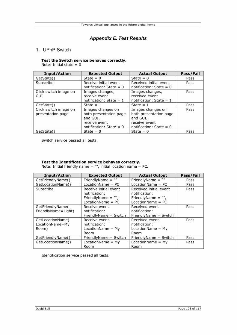
Towards virtual appliances in the future digital home
David Bull Page 103 of 117
Appendix E. Test Results
1. UPnP Switch Test the Switch service behaves correctly. Note: Initial state = 0
Input/Action Expected Output Actual Output Pass/Fail GetState() State = 0 State = 0 Pass Subscribe Receive initial event
notification: State = 0 Received initial event notification: State = 0
Pass
Click switch image on GUI
Images changes, receive event notification: State = 1
Images changes, received event notification: State = 1
Pass
GetState() State = 1 State = 1 Pass Click switch image on presentation page
Images changes on both presentation page and GUI, receive event notification: State = 0
Images changes on both presentation page and GUI, receive event notification: State = 0
Pass
GetState() State = 0 State = 0 Pass Switch service passed all tests. Test the Identification service behaves correctly. Note: Initial friendly name = “”, initial location name = PC.
Input/Action Expected Output Actual Output Pass/Fail GetFriendlyName() FriendlyName = “” FriendlyName = “” Pass GetLocationName() LocationName = PC LocationName = PC Pass Subscribe Receive initial event
notification: FriendlyName = ””, LocationName = PC
Received initial event notification: FriendlyName = ””, LocationName = PC
Pass
GetFriendlyName( FriendlyName=Light)
Receive event notification: FriendlyName = Switch
Received event notification: FriendlyName = Switch
Pass
GetLocationName( LocationName=My Room)
Receive event notification: LocationName = My Room
Received event notification: LocationName = My Room
Pass
GetFriendlyName() FriendlyName = Switch FriendlyName = Switch Pass GetLocationName() LocationName = My
Room LocationName = My Room
Pass
Identification service passed all tests.

Towards virtual appliances in the future digital home
David Bull Page 104 of 117
2. UPnP Light Bulb Test the Power service behaves correctly. Note: Light bulb starts up turned off.
Input/Action Expected Output Actual Output Pass/Fail GetPower() Power = 0 Power = 0 Pass Subscribe Initial event
notification: Power = 0 Received initial event notification: Power = 0
Pass
SetPower(Power=0) No change, no event notification
No change, no event notification received
Pass
SetPower(Power=1) Light turns on, event notification: Power = 1
Light turns on, received event notification: Power = 1
Pass
SetPower(Power=1) No change, no event notification
No change, no event notification received
Pass
GetPower() Power = 1 Power = 1 Pass SetPower(Power=0) Light turns off, event
notification: Power = 0 Light turns off, event notification: Power=0
Pass
SetPower(Power=true) Light turns on, event notification: Power = 1
Light turns on, received event notification: Power = 1
Pass
SetPower(Power=false) Light turns off, event notification: Power = 0
Light turns off, event notification: Power = 0
Pass
SetPower(Power=a) Receive error message Received error: “Target argument not Boolean”
Pass
SetPower(Power=2) Receive error message Received error: “Target argument not Boolean”
Pass
TogglePower() Light changes state to on, event notification: Power = 1
Light turns on, received event notification: Power = 1
Pass
TogglePower() Light changes state to off, event notification: Power = 0
Light turns off, event notification: Power = 0
Pass
Power service passed all tests.

Towards virtual appliances in the future digital home
David Bull Page 105 of 117
Test the Association service behaves correctly. Note: Switch and Light Bulb will be associated. Rules are stored on the Light Bulb, whose rule base is initially empty.
Input/Action Expected Output Actual Output Pass/Fail GetRuleCount() RuleCount = 0 RuleCount = 0 Pass GetRule(RuleID=0) All output arguments
are null All output arguments are null
Pass
DeleteRule(RuleID=0) Status = 0 Status = 0 Pass Subscribe Initial event
notification: UpdateNotification = null
Received initial event notification: UpdateNotification = null
Pass
Add rule to turn light on when switch state=1
RuleID = 0, receive event notification: UpdateNotification = Rule 0 added.
RuleID = 0, received event notification: UpdateNotification = Rule 0 added.
Pass
Add rule to turn light off when switch state=0
RuleID = 1, receive event notification: UpdateNotification = Rule 1 added.
RuleID = 1, received event notification: UpdateNotification = Rule 1 added.
Pass
GetRuleCount() RuleCount = 2 RuleCount = 2 Pass Click switch Light turns on Light turns on Pass Click switch Light turns off Light turns off Pass GetRule(RuleID=0) Original rule used to
turn light on when switch state=1
Original rule used to turn light on when switch state=1
Pass
GetRule(RuleID=1) Original rule used to turn light off when switch state=0
Original rule used to turn light off when switch state=0
Pass
DeleteRule(RuleID=1) Status = 1, receive event notification: UpdateNotification = Rule 1 deleted.
Status = 1, received event notification: UpdateNotification = Rule 1 deleted.
Pass
GetRuleCount() RuleCount = 1 RuleCount = 1 Pass ClearRules() Receive event
notification: UpdateNotification = Rules cleared.
Received event notification: UpdateNotification = Rules cleared.
Pass
GetRuleCount() RuleCount = 0 RuleCount = 0 Pass Click switch Nothing happens Nothing happened Pass
Association service passed all tests. Rule used to turn light on when switch state = 1:
VirtualAppName Light Switch RemoteUDN uuid:d9428667-0379-4c44-b6a4-f27977ed004b RemoteDescriptionURL http://10.0.0.20:8081/d9428667-0379-4c44-b6a4-
f27977ed004b/description.xml RemoteServiceID urn:www-uk-dave-com:serviceId:Switch RenmoteServiceType urn:www-uk-dave-com:service:Switch:1 RemoteVariableName State ComparisonType 1 RemoteVariableValue 1 LocalServiceID urn:www-uk-dave-com:serviceId:Power LocalServiceType urn:www-uk-dave-com:service:Power:1 LocalActionName SetPower LocalArgumentName Power LocalArgumentValue 1
The rule for turning the light back off is identical part from the RemoteVariableValue and the LocalArgumentValue which both equal 0.

Towards virtual appliances in the future digital home
David Bull Page 106 of 117
3. UPnP Timer Test the Timer service behaves correctly. Note: The Timer starts up in the finished state with a duration of 0 seconds.
Input/Action Expected Output Actual Output Pass/Fail GetDuration() Duration = 0 Duration = 0 Pass GetRemaining() Remaining = 0 Remaining = 0 Pass GetFinished() Finished = 1 Finished = 1 Pass GetAlarmURL() URL =
http://[deviceIP]/alarm.mp3
URL = http://10.0.0.20:8081/ alarm.mp3
Pass
Subscribe Initial event notification: Finished = 1
Received initial event notification: Finished = 1
Pass
SetDuration(Duration =30)
GUI displays 00:00:30 GUI displayed 00:00:30 Pass
SetDuration(Duration =a)
Receive error message Received error: “Target argument not Int”
Pass
SetDuration(Duration =-1)
Nothing happens Nothing happened Pass
GetDuration () Duration = 30 Duration = 30 Pass GetRemaining() Remaining = 30 Remaining = 30 Pass Start() Receive event
notification: Finished = 0, timer counts down for 30 seconds, receive event notification: Finished = 1
Received event notification: Finished = 0, timer counted down for 30 seconds, received event notification: Finished = 1
Pass
GetDuration() called during countdown
Duration = 30 Duration = 30 Pass
GetRemaining() called during countdown
Number between 0 and 30
Remaining = 15 Pass
Stop() called during countdown
Countdown stops, display resets to initial duration, receive event notification: Finished = 1
Countdown stopped, display reset to initial duration, received event notification: Finished = 1
Pass
Timer service passed all tests.

Towards virtual appliances in the future digital home
David Bull Page 107 of 117
4. UPnP Motion Sensor Test the Motion Sensor service behaves correctly.
Input/Action Expected Output Actual Output Pass/Fail GetMotion() Motion = 0 Motion = 0 Pass GetMotion() called immediately after mouse moved over window
Motion = 1 Motion = 1 Pass
Subscribe Receive initial event notification: Motion = 0
Received initial event notification: Motion = 0
Pass
Move mouse over window
Receive event notification: Motion = 1, shortly followed by Motion = 0
Received event notification: Motion = 1, shortly followed by Motion = 0
Pass
Motion Sensor service passed all tests.
5. UPnP Camera Test the Camera service behaves correctly. Note: The camera device was started with no previously captured image.
Input/Action Expected Output Actual Output Pass/Fail GetLastCaptureTime() LastCaptureTime = Thu
Jan 01 01:00:00 GMT 1970
LastCaptureTime = Thu Jan 01 01:00:00 GMT 1970
Pass
GetImageURL() ImageURL = http://[deviceIP]/capture.png
ImageURL = http://10.0.0.20:8081/capture.png
Pass
TakeImage() Image updates on GUI, and a return value of Status=1 is received
Image updated on GUI, and a return value of Status=1 was received
Pass
Subscribe Receive initial event notification: LastCaptureTime = last capture time
Received initial event notification: LastCaptureTime = Thu Mar 11 14:54:24 GMT 2004
Pass
TakeImage() Image updates on GUI, returns a value of Status=1, and event notification received of LastCaptureTime = current time
Image updated on GUI, return value of Status=1 received, and received event notification: LastCaptureTime = Thu Mar 11 14:56:37 GMT 2004
Pass
Camera service passed all tests. The first call the GetLastCaptureTime() returned “Thu Jan 01 01:00:00 GMT 1970” because the Java Date class measures time in seconds from a starting date of January 1st 1970.

Towards virtual appliances in the future digital home
David Bull Page 108 of 117
6. UPnP mDorm Test the Temperature service behaves correctly.
Input/Action Expected Output Actual Output Pass/Fail GetTemp() Current temperature Temp = 20.5000000 Pass Subscribe Receive initial event
notification: Temp = Current temperature
Received initial event notification: Temp = 20.5000000
Pass
Heat up temperature sensor
Receive event notifications every few seconds with temperature
Received event notifications every few seconds with temperature
Pass
Temperature service passed all tests. Test the Light Level service behaves correctly.
Input/Action Expected Output Actual Output Pass/Fail GetLightLevel() Current light level LightLevel = 31 Pass Subscribe Receive initial event
notification: LightLevel = Current light level
Received initial event notification: LightLevel = 31
Pass
Shine light on sensor Receive event notifications with new light level
Received event notification: LightLevel = 12
Pass
Cover sensor up Receive event notifications with new light level
Received event notification: LightLevel = 49
Pass
Light Level service passed all tests.
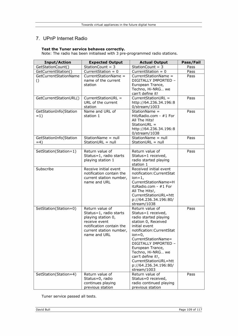
Towards virtual appliances in the future digital home
David Bull Page 109 of 117
7. UPnP Internet Radio Test the Tuner service behaves correctly. Note: The radio has been initialised with 3 pre-programmed radio stations.
Input/Action Expected Output Actual Output Pass/Fail GetStationCount() StationCount = 3 StationCount = 3 Pass GetCurrentStation() CurrentStation = 0 CurrentStation = 0 Pass GetCurrentStationName()
CurrentStationName = name of the current station
CurrentStationName = DIGITALLY IMPORTED – European Trance, Techno, Hi-NRG… we can’t define it!
Pass
GetCurrentStationURL() CurrentStationURL = URL of the current station
CurrentStationURL = http://64.236.34.196:80/stream/1003
Pass
GetStationInfo(Station=1)
Name and URL of station 1
StationName = HitzRadio.com - #1 For All The Hits! StationURL = http://64.236.34.196:80/stream/1038
Pass
GetStationInfo(Station=4)
StationName = null StationURL = null
StationName = null StationURL = null
Pass
SetStation(Station=1) Return value of
Status=1, radio starts playing station 1
Return value of Status=1 received, radio started playing station 1
Pass
Subscribe Receive initial event notification contain the current station number, name and URL
Received initial event notification:CurrentStation=1, CurrentStationName=HitzRadio.com - #1 For All The Hits!, CurrentStationURL=http://64.236.34.196:80/stream/1038
SetStation(Station=0) Return value of Status=1, radio starts playing station 0, receive event notification contain the current station number, name and URL
Return value of Status=1 received, radio started playing station 0, Received initial event notification:CurrentStation=0, CurrentStationName= DIGITALLY IMPORTED – European Trance, Techno, Hi-NRG… we can’t define it!, CurrentStationURL=http://64.236.34.196:80/stream/1003
Pass
SetStation(Station=4) Return value of Status=0, radio continues playing previous station
Return value of Status=0 received, radio continued playing previous station
Pass
Tuner service passed all tests.

Towards virtual appliances in the future digital home
David Bull Page 110 of 117
Test the AudioPlayback service behaves correctly. Note: When the radio starts up it does not start playing.
Input/Action Expected Output Actual Output Pass/Fail GetState() State = STOPPED State = STOPPED Pass GetURL() CurrentURL = null CurrentURL = null Pass Play() Returns Status=0 Returned Status=0 Pass Stop() Returns Status=0 Returned Status=0 Pass Subscribe Receive initial event
notification: CurrentURL = null, State = STOPPED
Received initial event notification: CurrentURL = null, State = STOPPED
Pass
SetURL(URL = http://64.236.34.196:80/stream/1038)
Receive event notification: CurrentURL=http://64.236.34.196:80/stream/1038
Received event notification: CurrentURL=http://64.236.34.196:80/stream/1038
Pass
Play() Returns Status=1, starts playing stream, receive event notification: State = PLAYING
Returned Status=1, started playing stream, received event notification: State = PLAYING
Pass
GetState() State = PLAYING State = PLAYING Pass GetURL() CurrentURL =
http://64.236.34.196:80/stream/1038
CurrentURL = http://64.236.34.196:80/stream/1038
Pass
Stop() Returns Status=1, stops streaming, receive event notification: State = STOPPED
Returned Status=1, stopped streaming, received event notification: State = STOPPED
Pass
Play() Returns Status=1, starts playing stream, receive event notification: State = PLAYING
Returned Status=1, started playing stream, received event notification: State = PLAYING
Pass
SetURL(URL = http://64.236.34.196:80/stream/1003)
Streaming stops, receive event notification: State = STOPPED, CurrentURL=http://64.236.34.196:80/stream/1038
Streaming stopped, received event notification: State = STOPPED, CurrentURL=http://64.236.34.196:80/stream/1038
Pass
SetURL(URL = abc) Receive event notification: CurrentURL=abc
Received event notification: CurrentURL=abc
Pass
Play() Returns Status=0 Returned Status=0 Pass AudioPlayback service passed all tests.

Towards virtual appliances in the future digital home
David Bull Page 111 of 117
Test the Clock service behaves correctly.
Input/Action Expected Output Actual Output Pass/Fail GetDateAndTime() The current date and
time in ISO 8601 format
2004-03-11-T16:53:39+01:00
Pass
GetMinutes() Minutes = 53 Minutes = 53 Pass GetHours() Hours = 16 Hours = 16 Pass GetDay() Day = 4 Day = 4 Pass GetDate() Date = 11 Date = 11 Pass GetMonth() Month = 3 Month = 3 Pass GetYear() Year = 2004 Year = 2004 Pass Subscribe Receive initial event
notification with current minutes, hours, day, date, month and year. Thereafter event notifications received whenever one of the above change.
Received initial event notification with current minutes, hours, day, date, month and year. Thereafter event notifications received whenever one of the above change.
Pass
Clock service passed all tests. Test the Display service behaves correctly. Note: When the radio starts up the message is blank.
Input/Action Expected Output Actual Output Pass/Fail GetMessage() Message = “” Message = “” Pass SetMessage(Message=Hello World)
Radio displays Hello World on the LCD.
Radio displayed Hello World on the LCD.
Pass
GetMessage() Message = Hello World Message = Hello World Pass Subscribe() Unable to subscribe
because there are no evented state variables.
Unable to subscribe because there are no evented state variables.
Pass
Display service passed all tests.

Towards virtual appliances in the future digital home
David Bull Page 112 of 117
8. UPnP A/V Device Test the VideoPlayback service behaves correctly.
Input/Action Expected Output Actual Output Pass/Fail GetState() State = STOPPED State = STOPPED Pass GetURL() CurrentURL = null CurrentURL = null Pass Play() Returns Status=0 Returned Status=0 Pass Stop() Returns Status=0 Returned Status=0 Pass Subscribe Receive initial event
notification: CurrentURL = null, State = STOPPED
Received initial event notification: CurrentURL = null, State = STOPPED
Pass
SetURL(URL = file:C:\movie.mpg)
Receive event notification: CurrentURL= file:C:\movie.mpg
Received event notification: CurrentURL= file:C:\movie.mpg
Pass
Play() Returns Status=1, video starts playing, receive event notification: State = PLAYING
Returned Status=1, video started playing, received event notification: State = PLAYING
Pass
GetState() State = PLAYING State = PLAYING Pass GetURL() CurrentURL =
file:C:\movie.mpg CurrentURL = file:C:\movie.mpg
Pass
Stop() Returns Status=1, stops playng, receive event notification: State = STOPPED
Returned Status=1, stopped playing, received event notification: State = STOPPED
Pass
Play() Returns Status=1, video starts playing, receive event notification: State = PLAYING
Returned Status=1, video started playing, received event notification: State = PLAYING
Pass
SetURL(URL = file:C:\image.png)
Video stops, receive event notification: State = STOPPED, CurrentURL= C:\image.png
Video stopped, received event notification: State = STOPPED, CurrentURL= C:\image.png
Pass
Play() Returns Status=1, image is displayed, receive event notification: State = PLAYING
Returned Status=1, image was displayed, received event notification: State = PLAYING
Pass
SetURL(URL = abc) Image is removed, receive event notification: State = STOPPED, CurrentURL= abc
Image was removed, received event notification: State = STOPPED, CurrentURL= abc
Pass
Play() Returns Status=0 Returned Status=0 Pass VideoPlayback service passed all tests.

Towards virtual appliances in the future digital home
David Bull Page 113 of 117
9. UPnP Rule Proxy Test the RuleProxy service behaves correctly. Note: The UPnP Switch and Siemens Test Device will be associated. Rules are stored on the RuleProxy, whose rule base is initially empty.
Input/Action Expected Output Actual Output Pass/Fail GetRuleCount() RuleCount = 0 RuleCount = 0 Pass GetRule(RuleID=0) All output arguments
are null All output arguments are null
Pass
DeleteRule(RuleID=0) Status = 0 Status = 0 Pass Subscribe Initial event
notification: UpdateNotification = null
Received initial event notification: UpdateNotification = null
Pass
Add rule to turn light on when switch state=1
RuleID = 0, receive event notification: UpdateNotification = Rule 0 added.
RuleID = 0, received event notification: UpdateNotification = Rule 0 added.
Pass
Add rule to turn light off when switch state=0
RuleID = 1, receive event notification: UpdateNotification = Rule 1 added.
RuleID = 1, received event notification: UpdateNotification = Rule 1 added.
Pass
GetRuleCount() RuleCount = 2 RuleCount = 2 Pass Click switch Light turns on Light turns on Pass Click switch Light turns off Light turns off Pass GetRule(RuleID=0) Original rule used to
turn light on when switch state=1
Original rule used to turn light on when switch state=1
Pass
GetRule(RuleID=1) Original rule used to turn light off when switch state=0
Original rule used to turn light off when switch state=0
Pass
DeleteRule(RuleID=1) Status = 1, receive event notification: UpdateNotification = Rule 1 deleted.
Status = 1, received event notification: UpdateNotification = Rule 1 deleted.
Pass
GetRuleCount() RuleCount = 1 RuleCount = 1 Pass ClearRules() Receive event
notification: UpdateNotification = Rules cleared.
Received event notification: UpdateNotification = Rules cleared.
Pass
GetRuleCount() RuleCount = 0 RuleCount = 0 Pass Click switch Nothing happens Nothing happened Pass
RuleProxy service passed all tests.

Towards virtual appliances in the future digital home
David Bull Page 114 of 117
Rule used to turn light on when switch state = 1:
VirtualAppName Siemens Light Switch InputUDN uuid:d9428667-0379-4c44-b6a4-f27977ed004b InputDescriptionURL http://10.0.0.20:8082/d9428667-0379-4c44-b6a4-
f27977ed004b/description.xml InputServiceID urn:www-uk-dave-com:serviceId:Switch InputServiceType urn:www-uk-dave-com:service:Switch:1 InputVariableName State ComparisonType 1 InputVariableValue 1 OutputDescriptionURL uuid:siemensTestDevice OutputDescriptionURL http://10.0.0.20:81/siemensTestDevice/description.xml OutputServiceID urn:schemas-upnp-org:serviceId:SwitchPower:1 OutputServiceType urn:schemas-upnp-org:service:SwitchPower:1 OutputActionName SetTarget OutputArgumentName newTargetValue OutputArgumentValue 1
The rule for turning the light back off is identical part from the InputVariableValue and the OutputArgumentValue which both equal 0.

Tow
ards
virt
ual
applian
ces
in t
he futu
re d
igital
hom
e
Dav
id B
ull
Pa
ge
115 o
f 117
App
endi
x F.
Gan
tt C
hart
s

Tow
ards
virt
ual
applian
ces
in t
he futu
re d
igital
hom
e
Dav
id B
ull
Pa
ge
116 o
f 117

Towards virtual appliances in the future digital home
David Bull
Appendix G. Source Code and Documentation
Source code, documentation, an electronic copy of this report in both MS Word and PDF
format, and all the programs used (Java, Tomcat, Cocoon, etc.) are all included on
attached the CD.