towards walking on mars - automation & robotics...
TRANSCRIPT

TOWARDS WALKING ON MARS
M. Latta, C. D. Remy, M. Hutter, M. Höpflinger, R. Siegwart
Autonomous Systems Lab, Institute of Robotics and Intelligent Systems
Swiss Federal Institute of Technology (ETHZ),
Tannenstrasse 3, 8092 Zurich
{martin.latta, christian.remy, marco.hutter, markus.hoepflinger,
roland.siegwart}@mavt.ethz.ch
ABSTRACT
This paper presents a quadruped robot that enables
novel locomotion concepts for extremely rough terrain.
The system was built for upright walking but its wide
range of motion in all joints allows switching to a
turtle-like crawling gait when loose soil or steep slopes
are encountered. Furthermore, a robust design paired
with special manoeuvres that allow recovering after
tipping over make the system very robust against
“mission failure”. The platform was initially tested in
the ESA Lunar Robotics Challenge 2008 and since
then further developed for completely autonomous
operation in rough and unknown terrain.
1. INTRODUCTION
In 2008, the European Space Agency (ESA) organized
the Lunar Robotics Challenge (LRC) in Tenerife to
simulate a mission on the moon [1,2]. The task was to
deploy a robot from a landing site located close to a
crater, climb into the crater, collect a sample, and
return to the landing base. The background behind this
simulated mission is to examine the assumption that
hydrogen rich ore may be found on the crater ground
where no sunlight reaches. Scientists believe that in
these depths of lunar craters water might be preserved
frozen which could be crucial, if one day mankind
wants to establish a permanent base on the moon. The
conditions encountered in such a crater make
exploration very different from common missions. The
crater edge is extremely steep (about 40°) and will be
covered by rocks, boulders, and terraces. Landslides
can occur every time the sand on the crater's slope is
touched. Everything that makes the crater interesting
for science (no sunlight, cold temperature, depth)
makes it hard to explore.
Facing these harsh conditions, the usual approach of
using a wheeled rover is pointless. The rover would
grave itself into the loose gravel while trying to climb
the crater slope and would not be able to overcome
high obstacles such as rocks. Therefore, new platforms
with new locomotion principles are required for such
situations where wheeled rovers can no longer operate.
We propose a highly agile, fully actuated quadruped
platform with a total of 12 degrees of freedom (DoF) to
perform such tasks. The robot walks upright on solid
surface by careful foothold planning (Fig. 1), but
switches to a turtle-like crawling gait when it comes to
loose gravel and soil and/or extremely steep slopes.
This special gait features a larger contact surface in
combination with a very low positioned centre of
gravity (CoG) that ensures static stability even under
conditions as encountered in the LRC. In case of
failure, the presented platform is able to recover from a
complete rollover due to the impressive range of
motion that is achieved by a differential drive in the hip
joint.
While during the LRC an operator manually selected
gait parameters like speed or turning rate, the platform
was subsequently equipped with a real-time simulation
and planning software for autonomous operation. Gait
or even more foothold selection can now be based on
camera and haptic feedback.
2. SYSTEM DESCRIPTION
We developed a quadruped robot with a total weight of
about 15kg and linear dimensions in the range of 0.5m.
The proposed platform combines a lightweight
structure with powerful actuation that makes it not only
well suited for a lunar mission but also easy to handle
by a single operator as a research platform. With a
payload capability of more than 5kg (for a standard
walking gait, largely increased for crawling gaits), the
robot is able to collect as well as to transport
respectable amounts of specimen, but also to carry
Figure 1: The robot during walking at the testing
site of the El Teide during the LRC in Tenerife 2008.
large and sophisticated sensors. With regard to the
harsh environment that the robot faced in this
challenge, the chassis is built of carbon-kevlar hybrid
fibres, granting for high torsional stability as well as
for good robustness against collisions with a minimal
mass.
2.1. Actuation
The robot shows a total of 12 degrees of freedom - 3
per leg - which are split into one DoF in the knee and
two in the hip. A bevel gear drive in the knee allows
for flexion and extension of about +90° and -160°
respectively. Hip abduction/adduction and
flexion/extension is realized using a differential gear
drive (Fig. 2) which couples two actuators and enables
a wide range of motion of about ±180° for
flexion/extension (Fig. 2A) and ±45° for
abduction/adduction (Fig. 2B). This maximizes the
robot manoeuvrability (Fig. 3) which is crucial when it
comes to traverse challenging terrain. As a second
beneficial effect, both hip motors are placed within the
main body such that the leg segment mass is reduced
and the motor and gearboxes can be entirely sealed
from the environment (dust protection). To be able to
utilize this large range of motion, the robot is equipped
with 12 DC motors (Maxon RE25, 24V) with a gear-
box reduction ratio of 79:1. The detailed mechanical
specifications are summarized in Tab. 1.
2.2. Electronics and control
Within the Lunar Robotics Challenge, the robot was
manually controlled using an external Laptop which is
linked by an IEEE 802.11 Wi-Fi connection to the
onboard single-board RIO (sbRIO) from National
Instruments (NI) that combines an FPGA and a real
time processor. The user can apply certain high level
commands, such as heading, velocity, or gait
transmission by using a joystick. The movement itself
is generated by following pre-implemented velocity
and position trajectories on the sbRIO. The sbRIO
communicates over a CAN-bus system with the low
level Maxon EPOS motor controllers that are
responsible for velocity as well as current control.
Energy supply is provided off-board by a cable which
was additionally designed to hold as a tethering device
for active support when the terrain is too steep.
Following pre-planned trajectories clearly limits the
variability of the robot and requires for a human
operator. Subsequent to the LRC, the manual operator
was replaced by a simulation and planning
environment [3]. This allows for real time motion as
well as foot hold planning based on various sensor
feedback that can monitor the main body
position/orientation (IMU) as well as the environment
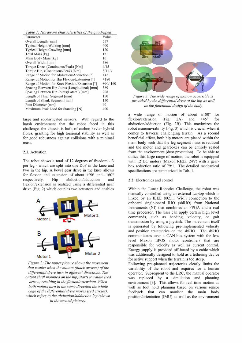
Figure 3: The wide range of motion accessible is
provided by the differential drive at the hip as well
as the functional design of the body
Figure 2: The upper picture shows the movement
that results when the motors (black arrows) of the
differential drive turn in different directions. The
output shaft mounted on the hip, starts to rotate (red
arrow) resulting in the flexion/extensiont. When
both motors turn in the same direction the whole
cage of the differential drive moves (red circles),
which refers to the abduction/adduction leg (shown
in the second picture).
Table 1: Hardware characteristics of the quadruped Parameter Value
Overall Length [mm] 557
Typical Height Walking [mm] 400
Typical Height Crawling [mm] 120
Total Mass [kg] 15
Main Body Mass [kg] 10
Overall Width [mm] 386
Torque Knee, (Continuous/Peak) [Nm] 4/15
Torque Hip, (Continuous/Peak) [Nm] 3/11.3
Range of Motion for Abduction/Adduction [°] ±45
Range of Motion for Hip Flexion/Extension [°] ±180
Range of Motion for Knee Flexion/Extension [°] +90/-160
Spacing Between Hip Joints (Longitudinal) [mm] 389
Spacing Between Hip Joints(Lateral) [mm] 208
Length of Thigh Segment [mm] 150
Length of Shank Segment [mm] 150
Foot Diameter [mm] 40
Maximum Peak Load for Standing [N] 400

(stereo cameras, kinect sensor[4]).
2.3. LRC setup
The challenging environment with a steep crater with
loose gravel and soil, no direct line of sight from the
operator to the robot, no GPS availability for
localization, as well as the bad illumination conditions
during night required additional means for a
completion of the proposed task. Our team tackled
these problems by a collaboration of the presented
quadruped with two additional robots. CRABli [5]
(Fig. 5, on the left), a six wheel rover equipped with a
passive suspension system optimized for rough terrain,
was positioned at the crater edge to establish the
communication link as well as to provide birds-eye
view of the crater using a high resolution pan-tilt-zoom
(20x) camera. A stationary robot remained at the
landing station and was responsible for cabling and for
support during ascending in the steepest slope.
For sample detection, the quadruped robot was
equipped with pan-tilt cameras and bright illumination
at both ends. Due to the challenging ground, the whole
robot was sealed with a sort of jumpsuit to protect it
from dust. Additional skid plates underneath the main
body and the shanks improved friction and kept the
direction while climbing the high inclined slopes.
3. LOCOMOTION
3.1. Gaits
The high range of motion in all joints pays out in a
large variety of gaits that can be applied depending on
the terrain properties:
A) Upright walking
For locomotion on solid ground, a standard walking
Figure 5: The quadruped and the supportive
wheeled rover CRABli in front of the crater rim at
the LRC testing site in Tenerife.
Figure 4: The large range of motion especially in the hip joint allows for unconventional gait creation such as
crawling. The robot abducts the thigh about 45° ((4) and (6)) to propulse itself in a turtle-like manner which is
useful to explore hard accessible terrain.
Figure 6: Obstacles of the size of the wheel
diameter of the rover are mostly insurmountable
obstacles, whereas for legged exploration
platforms such barriers can be managed.

gait is applied with a step length of about 0.2m and a
ground clearance of 0.25m. Thereby the overall CoG
respectively ZMP (Zero Moment Point) [6] is kept
within the support polygon of the 3 supporting feet
while the swing leg is moved to the subsequent
foothold position. This gait is especially interesting
when large but solid obstacles or gaps in the ground
must be conquered – where this robot has clear
advantages compared to a same sized rover due to a
ground clearance that is in the range of the leg length
(Fig. 6)
B) Crawling
Upright walking becomes inappropriate when it comes
to loose soil and/or landslide (which both were
encountered in the LRC). The feet would sink into the
ground, causing the robot to stumble and fall over.
Inspired by nature, a turtle-like crawling gait was
adopted that keeps the CoG at the lowest point possible
(Fig. 8). The support surface is largely increased since
at every instant in the whole gait cycle, either the entire
main body or all four shank plates are in ground
contact. The larger contact surface is additionally
beneficial considering sinking in the loose soil. Fig. 4
shows a picture series of a single crawl cycle on flat
ground. The required joint positions (especially (2)
and (6)) are only achievable due to the high range of
motion of the hip joint (differential drive).
C) Specialized manoeuvres
The biggest challenge for planetary exploration devices
is to recover from situations where the robot is stuck
and can no longer be operated. The worst case is a
complete tilt over on the top of the robot, which
generally means that the mission fails, at least for a
rover. The presented quadruped platform can cope
with this situation: First, actuators, sensor and
electronics will survive the roll-over since they are
protected either by the side plates of the thigh or the
shock resistant carbon-kevlar main body hull. Second,
the high manoeuvrability allows recovering from any
configuration (lateral or supine position) by performing
the motion depicted in Fig. 7.
Figure 8: The static stability margin left in a steep
slope situations is higher for the legged application
(shown in an arachnoid configuration on the right).
The system is more robust against disturbances and
dynamic effects compared to the rover on the left
side.
Figure 7: The picture sequence shows a rollover of the robot after tilting on its back. The first step is to position the
legs of one side such that a support area is built on which further actions can be performed (frame 2). The second
step is to position the main body above the support area by pushing with the legs of the other side (frame 3 and 4).
Afterwards the unloaded legs are turned to the belly-side of the robot (frame 5). Using now the loaded legs to turn
the torso and the upper legs to buckle (frame 6), the robot reaches its initial position (frame 7) from which it can
start walking or crawling.

3.2. Terrain classification
During the LRC, the operator decided what gait should
be applied depending on the ground characteristics,
namely inclination, material consistency, or obstacle
occurrence. Towards more autonomy, the robot has to
select gait, speed or foothold on-line depending on
visual and/or haptic feedback of the environment.
Using the presented quadrupedal platform, we
developed a haptic terrain classification algorithm [7]
which can identify the decomposition of the soil and
the small scale surface geometry with a high success
rate. During a test cycle for which the robot has to
stand on point, the foot executes a movement similar to
scratching while measuring the resulting forces with a
force sensing device embedded in the foot as well as
the sinkage rate and motor current. Different features
were extracted from this data and used for training and
classification by a multiclass AdaBoost [8] machine
learning algorithm. In preliminary test series, the robot
could correctly classify about 94% of the terrain shapes
and about 73% of the surface samples. Depending on
the material (solid/compliant and the gravel size of the
compliant material) a gait can be chosen suiting the
current environmental conditions.
4. CONCLUSION & OUTLOOK
The presented platform and locomotion principles
demonstrated that legged robotic systems are a
promising approach for future exploration missions.
The high manoeuvrability increases the versatility of
the system, such that very challenging (in terms of
obstacles, inclination, and surface characteristics)
terrain can be safely traversed. Within the Lunar
Robotics Challenge, we proposed a successful crawling
gait that can cope with extreme slopes in combination
with loose gravel and soil. In addition thereto, our
quadruped demonstrated high failure robustness: even
in the worst case of a complete tilt over, the robot is
able to recover.
Within the LRC, gait selection (including speed,
turning angle, step length, crawl/walk/...) was chosen
by an operator. In subsequent research conducted at
our lab, a simulation environment for foothold
planning and execution was integrated that the system
can operate autonomously. We are now at the stage
where camera feedback in combination with IMU data
are fused to estimate the robots position in unknown
environment as well as to map the environment. This
is augmented by haptic feedback from the force sensors
for optimal foothold planning with regard to shape and
consistency of the environment – leading to an
autonomous quadruped robot for future explorations.
AKNOWLEDGEMENT
The authors would like to thank the European Space
Agency for the financial support and the opportunity to
participate in the challenge as well as the whole LRC
team for their contribution.
REFERENCES
1. Alicino, S et al. (2009). ”A Rough-Terrain, Casting
Robot for the ESA Lunar Robotics Challenge”, In
Proc IEEE/RSJ International Conference on
Intelligent Robots and Systems, St. Luis, USA
2. Schwendner, J. et al. (2009), CESAR: ”A Lunar
Crater Exploration and Sample Return Robot”, In
Proc IEEE/RSJ International Conference on
Intelligent Robots and Systems, St. Luis, USA
3. Remy, C. D. et al. (2010), “Walking and Crawling
with ALoF – A Robot for Autonomous
Locomotion on Four Legs”, In Proc. IEEE/RSJ
International Conference on Climbing and
Walking Robots (CLAWAR), Nagoya, Japan
4. Pommerleau, F. et al. (2011), “Tracking a Depth
Camera: Parameter Exploration for Fast ICP”,
Submitted to IEEE/RSJ International Conference
on Intelligent Robots and Systems (IROS) 2011,
San Francisco, California, USA
5. Thueer, T. & Siegwart, R. (2010), “Mobility
Evaluation of Wheeled All-Terrain Robots”,
Robotics and Autonomous Systems 58, pp 508-
519
6. Vukobratovic, M. & Borovac, B. (2004), ”Zero
Moment Point – Thirty Five Years of its Life”.
International Journal of Humanoid Robotics Vol.
1, No31, pp157-173
7. Hoepflinger, M. A. et al. (2010),”The Quadruped
ALoF and a Step towards Real World Haptic
Terrain Classification”, In Proc 12th Mechatronics
Forum Biennial International Conference 2010,
Zurich, Switzerland
8. Hoepflinger, M. A. et al. (2010), “Haptic Terrain
Classification for Legged Robots”, In Proc.
IEEE/RSJ International Conference on Climbing
and Walking Robots (CLAWAR), Nagoya, Japan