towbar fitting instructions to suit holden vf commodore ... · 5. inside the cabin, behind the...
TRANSCRIPT

Towbar Fitting Instructions To Suit HOLDEN VF COMMODORE UTE 2013 ON
Part Number QTHD518L Rating 1600/160 kg
PLACE THESE INSTRUCTIONS IN THE VEHICLE’S GLOVEBOX AFTER INSTALLATION IS COMPLETED
Rev: B Page 1 Issue Date: 02-04-2014
Cequent Customer Service Ph: 1800 812 017 Fax: 03 9898 3299
Email: [email protected] Post: PO Box 4050, Dandenong South VIC 3175
FOR TRAILER TOWING PURPOSES ONLY For towing capacity details please refer to vehicle owner’s manual or to the manufacturer. Overloading can void your warranties.
WARNING: 1. Do not, drill, cut, weld or otherwise modify the tow bar. 2. If you are using electric welding on a motor vehicle, always check that the vehicle is not equipped with electronic
engine or instrument management equipment. Failure to do so could destroy any onboard computers. If in doubt, check with the vehicle's manufacturer.
3. The high tensile fasteners supplied with this product were used to achieve the specified rating. If replacement is required ensure that fasteners of the same rating & quality are used. Contact an authorised Trailboss dealer if further information is required.
4. If TBM is used in inverted position tow ball may make contact with rear tailgate when lowered, which could cause damage.
General: 1. Ensure all hardware items have been included refer to assembly diagram. 2. It is recommended that the instructions are read through and completely understood before making any attempt
to fit this product. 3. Be wary of any changes to vehicle designs or other accessories that may conflict with the installation of this
product. 4. Before drilling ensure that the area is clear of fuel, electrical & other components. 5. All holes drilled into the body panels shall have all burrs & swarf removed then coated with a suitable rust
preventative paint. 6. For vehicles that require the bumper to be cut. Ensure cut out area is in correct position on the vehicle prior to
cutting the bumper. 7. The high tensile fasteners supplied with this product were used to achieve the specified rating. If replacement is
required ensure that fasteners of the same rating & quality are used. Contact an authorized Trailboss dealer if further information is required.
8. Ensure that all hardware is fastened to torque list below check fasteners on regular basis. 9. Tow bar load rating sticker provided with this product shall be conspicuously located on inside rear end of the
driver's door. (See diagram below). 10. Trailboss recommends that you check your tow ball to ensure that it complies with the Australian standards
AS 4177.2. 11. PLEASE NOTE: It is advised to remove your lug or tbm when not actually towing so as to produce a clear view of
the vehicles registration plate if obscured, and to also provide maximum available departure angle 12. Pull Pin must be fit in down position.
Tow bar Maintenance and Care. Trailboss recommends that bolt torque’s, as listed below, are routinely and regularly inspected and checked for correct tension. Replace any worn or defective parts. We recommended to remove Tow Ball Mounts (TBM’s, tongues or lugs) when not being used for any considerable length of time. So as to avoid injury, when not towing it is suggested that the tongue, Pull Pin and R-clip are removed then stored in a safe, clean and dry place, away from excessive moisture. Hitch Pull Pins and spring “R” clips are regularly checked for proper installation. Replace any worn or defective parts.
Place load rating sticker inside driver’s door here
RECOMMENDED ASSEMBLY TORQUE LISTING Diameter Grade 8.8 Bolt M6 9.5 Nm M8 21.7 Nm M10 43.4 Nm M12 77.3Nm M14 146 Nm M16 189.8 Nm

Cequent Customer Service Ph: 1800 812 017 Fax: 03 9898 3299
Email: [email protected] Post: PO Box 4050, Dandenong South VIC 3175
QTY DESCRIPTION ITEM NO 1 WELDED ASSEMBLY 1 1 T.B.MOUNT 21161 2 4 SPACER TUBE 3 4 WASHER FLAT M14x28x3 4 4 SPRING WASHER 12x4x2.5 5 4 M12x1.75P NUT 6 4 M12x130x8.8 COACH BOLT 7 2 M8x19.5x1.6 WASHER 8 2 M8 SPRING WASHER 9 2 M8x30 BOLT 10 1 BOOT MOUNT PASSENGER SIDE 11 1 BOOT MOUNT DRIVER SIDE 12 1 M10x25 1.5P BOLT 13 1 NUT M10x1.5P 14
COLLAR COVER PULL PIN R CLIP
WIRING LOOM LR LABELFITTING INSTRUCTION
ADDITIONAL ITEMS
CP LABEL PLUG BRACKET NUT NYLOC

Cequent Customer Service Ph: 1800 812 017 Fax: 03 9898 3299
Email: [email protected] Post: PO Box 4050, Dandenong South VIC 3175
INSTRUCTION:
1. Remove rear Tub liner from inside cargo area via a. Removing 3 x Phillips head screws at rear end of tub liner. b. Remove 2 x plastic trim plugs from rear end of tub liner each side. c. Remove 3 x ties down points each side of the tub liner via torx bolts. d. Compress tub at the sides then remove tub from the rear compartment of the utility so that easy access is
gained to fit mounting system for towbar.
2. Fitment of crush tubes , boot plates & coach bolts a. Pass a screwdriver from underneath the vehicle through existing hole into the floor pan of the vehicle
tray. b. Slide the crush tube over the screwdriver. c. Align the boot plate with existing holes inside floor pan of vehicle tray then pass the screwdriver through
the square hole in the boot plate. d. Feed the M12 coach bolt through the square hole in the boot plate pushing the screwdriver out allowing
the crush tube to remain inside the chassis. e. Repeat this for the three remaining mounting points inside the rear floor plan of the vehicle.
3. Removal of rear bumper bar skin via
a. From inside each wheel arch remove 1 x self tapper at the top of the wheel arch each side of the vehicle. b. 3 x self tappers inside each wheel arch to outer side of mud flap. c. 2 x plastic trim plugs each side of the of wheel arch underneath mud flap. d. Let the mud flaps hang at each side. e. Remove 4 x plastic trim buttons from underside of bumper bar skin.
4. Removal of rear bumper bar skin via
a. Flex bumper bar skin out at the side then pull rear ward some force may be required caution two person lift required.
b. Place the bumper bar skin on suitable bumper stands so not to damage ready for bumper cut. c. Using a small hacksaw or similar device carefully cut around the Holden factory indent in the rear fascia
of the bumper bar skin.
Holden factory indent on rear bumper bar skin. Carefully cut around the
indent be sure to clean all rough edges.
File corner radius with a round file to ensure that cut is neat

Cequent Customer Service Ph: 1800 812 017 Fax: 03 9898 3299
Email: [email protected] Post: PO Box 4050, Dandenong South VIC 3175
5. Fitment of Towbar to the vehicle via
a. Remove & discard the lower of the two tailgate hinge retaining bolts. b. Remove exhaust bracket bolts, lower exhaust ( LH & RH sides of vehicle) see fig 1 c. Offer Towbar to the underside of the chassis rails so that the slots in the side arms align with the bolts
hanging down through the chassis rails. d. Fasten loosely with washers & nuts provided. e. Fit M8 bolts & washers provided to lower section of the tailgate hinge, passenger side shown repeat for
drivers side. f. Fasten the rear most M12 nuts first to the torque listing. g. Then fasten the rest of the bolts & nuts to the torque listing. h. Raise exhaust, refit exhaust bracket bolts. ( LH & RH sides of vehicle) see fig 1
6. Refit the bumper bar skin via a. Carefully refit the bumper bar skin to rear of the vehicle so that the hitch box section fits through the cut
out in the bumper bar skin. b. Caution two person lift required to refit the bumper bar skin. c. Refit all the fixings for the bumper bar skin in the reverse of steps 4a through to 3a. d. Refit the rear tub liner in the reverse of steps 1d through to 1a. e. Fit the trailer ball mount & pull pin with spring cotter pin as shown in the assembly diagram.
Fig 1
Remove exhaust bracket bolt(s) and place to side
Lower exhaust for easier fitment of towbar (side arm)

Wiring Loom Fitting Instructions To Suit Holden Commodore VF Ute
Part Number 100972-WL
Page 1 of 4 Issue Date 15-08-16 Cequent Customer Service
Ph: 1800 812 017 Fax: 03 9797 3299 Email: [email protected]
Post: PO Box 4050, Dandenong South VIC 3175
Wiring Loom Installation Instructions
Holden Commodore VF UTE
Part No: 100972-WL ECU Required: 04839
Tail Harness Length Required: 1800mm
Wiring Loom Installation Time: Approx 20 Mins

Wiring Loom Fitting Instructions To Suit Holden Commodore VF Ute
Part Number 100972-WL
Page 2 of 4 Issue Date 15-08-16 Cequent Customer Service
Ph: 1800 812 017 Fax: 03 9797 3299 Email: [email protected]
Post: PO Box 4050, Dandenong South VIC 3175
1. At the back of the rear LHS, remove the LHS access panel to reveal the vehicle 8-way
break-out connector and remove its blanking cap. 2. In the access panel cavity, drill a 30mm hole (1) into the vehicle sheet metal area.
Connect the trailer patch (P/No: 100972-WL) connector (2) to the mating vehicle break-out connector (3).
3. At the rear of the vehicle, secure the tail harness socket to the towbar mounting plate using the supplied M4 fasteners. Route the tail harness towards the LHS across the rear of the towbar, underneath the vehicle and into the tray through the previously drilled out hole ensuring the tail harness grommet is seated correctly.
4. Connect the tail harness 8-way connector to the trailer patch mating connector. 5. Inside the cabin, behind the passenger seat, locate the fuse panel covering and open it to
gain access to the fuses underneath. 6. Remove the positive terminal (1) from the battery. Remove the nut (2) from above the
fuse panel area and then dislodge the whole fuse panel (3) to gain access to the 18-way and 2-way connectors underneath the fuse panel. Remove the white secondary lock from the 18-way connector and connect to the supplied ECU harness 18-way mating connector ensuring the connector wires line up GREEN to GREEN/BLACK.
Wiring Loom Fitting Instructions To Suit Holden Commodore VF Ute
Part Number 100972-WL
Page 3 of 4 Issue Date 15-08-16 Cequent Customer Service
Ph: 1800 812 017 Fax: 03 9797 3299 Email: [email protected]
Post: PO Box 4050, Dandenong South VIC 3175
7. Cut the RED and BLACK wires off the 2-way break-out connector.
8. Crimp the supplied terminals onto the wires and then insert the crimped RED wire into
pin 6 of the ECU harness connector and the crimped BLACK wire into pin 7 of the ECU harness connector.
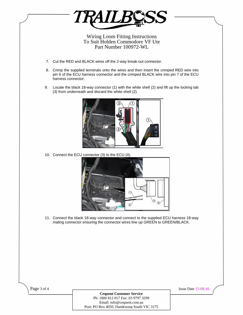
9. Locate the black 18-way connector (1) with the white shell (2) and lift up the locking tab
(3) from underneath and discard the white shell (2).
10. Connect the ECU connector (3) to the ECU (4).
11. Connect the black 18-way connector and connect to the supplied ECU harness 18-way mating connector ensuring the connector wires line up GREEN to GREEN/BLACK.
Wiring Loom Fitting Instructions To Suit Holden Commodore VF Ute
Part Number 100972-WL
Page 4 of 4 Issue Date 15-08-16 Cequent Customer Service
Ph: 1800 812 017 Fax: 03 9797 3299 Email: [email protected]
Post: PO Box 4050, Dandenong South VIC 3175
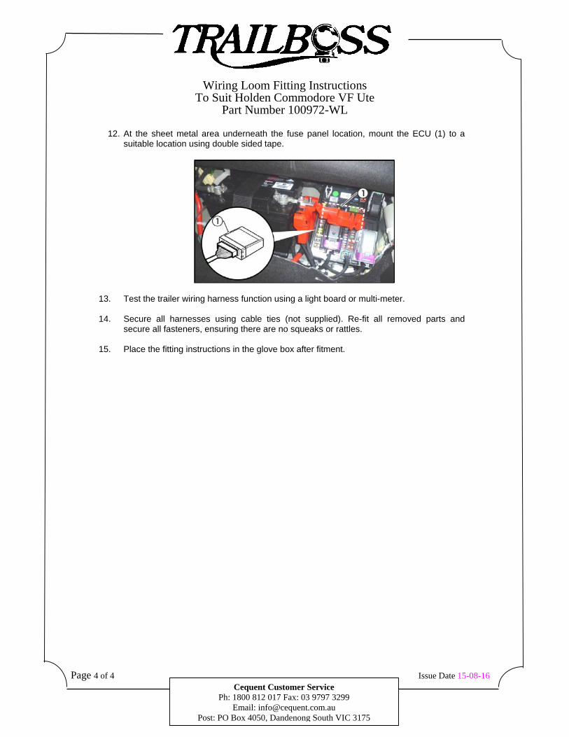
12. At the sheet metal area underneath the fuse panel location, mount the ECU (1) to a suitable location using double sided tape.
13. Test the trailer wiring harness function using a light board or multi-meter.
14. Secure all harnesses using cable ties (not supplied). Re-fit all removed parts and secure all fasteners, ensuring there are no squeaks or rattles.
15. Place the fitting instructions in the glove box after fitment.

FITTING INSTRUCTIONSSilent Anti-Rattle Hitch Pin (PRO001)
Pro SeriesPO BOX 4050, Dandenong South, VIC 3164 [email protected] I 1800 812 017 www.pro-series.com.au
• These fitting instructions are supplied to ensureunderstanding of how the HITCH PIN should be fitted andused correctly.
• Once installed, we recommend ALL instructions are kept andplaced in the vehicle glove box.
NOTE: Routine maintenance and inspection of the towbar & HITCH PIN is required. Regularly inspect for wear and check the tightness of the Hitch Pin. Follow instructions below to retighten the nut when necessary.
*Do not tow with your vehicle if the R CLIP or the HITCH PIN isloose or missing. Replacement parts are available from your Pro Series Distributor.
Hitch Pin Nut
R-Clip
Hitch Pin
Fig 1. Silent Anti-Rattle Hitch Pin assembly
Fig 2. Installation of Trailer Ball Mount Fig 3. Silent Anti-Rattle Hitch Pin orientation
Insert Trailer Ball Mount (TBM) into towbar HITCHBOX, aligning hole in TBM SHANK with hole in HITCHBOX (Fig 2).
Insert HITCH PIN through hole in HITCHBOX and hole in TBM SHANK; ensure the LOCATORS are inserted into the NOTCHES in the HITCHBOX (Fig. 3).
STEP 1
STEP 2
Screw HITCH PIN NUT onto HITCH PIN ; tighten HITCH PIN NUT until fingerSTEP STEP 3 3 tight, ensuring TBM is restrained from movement.
Tighten HITCH PIN NUT by turning nut a further 1/8th of a turn in the clockwise direction using a 24mm spanner (Fig. 4).
STEP 4
Install HITCH PIN R CLIP through the hole on the HITCH PIN (Fig. 1). STEP 5
Step 4
Fig 4. Tightening of Silent Anti-Rattle Hitch Pin Nut
Notches
Locators
STEP 3