tower/chimney fixture mount system -...
TRANSCRIPT

ALS-XXX-34M-2C-JB
A. ELECTRICAL AND SIGNAL DISCONNECT UNIT WITH MULTI-PIN CONNECTOR.
B. DISCONNECT UNIT FITTER WITH PULLEY AND
U-BOLT MOUNTING. C. DIVIDED PIPE ARM: 2-3/8 IN. O.D. SEPARATES
CONTROL CABLE AND ELECTRICAL/SIGNAL WIRES.
D. TOWER MOUNTED FITTER WITH PULLEY
HOUSING AND MOUNTING BRACKETS TO STRAP TO TOWER (STRAPS BY OTHERS).
E. ELECTRICAL CORD STRAIN RELIEF F. AERONAUTICAL FIXTURE (BY OTHERS). G. CONTROL CABLE CONSTRUCTED OF 5/32 INCH
DIA. STAINLESS STEEL 7X19 CABLE. H. ELECTRICAL/SIGNAL WIRES & CONNECTOR
(BY OTHERS). OPTIONAL 1 PCE ELECT/SIGNAL CABLE FROM DISCONNECT UNIT TO BASE.
J. 1.5” CONDUIT (BY OTHERS). K. CONDUIT CLAMPS EVERY 10 FT. (BY OTHERS). L. CAST ALUMINUM SECURITY LOCKING BOX.
(LOCK BY OTHERS). M. STAINLESS STEEL MOUNTING BRACKETS
WITH SLOTS FOR STRAPPING TO POLE OR OTHER STRUCTURE. STRAPS BY OTHERS.
N. FIXTURE GUIDE CABLE, 5/32” STAINLESS
STEEL ALLOWING FIXGTURE TO SAFELY FOLLOW GUIDE TO GROUND.
O. TOWER/CHIMNEY (BY OTHERS).
P. GUIDE CABLE ANCHOR IN GROUND (By
Others).
Q. JUNCTION BOX (OPTIONAL) WITH 1.5” CONDUIT MOUNTING OPENING.
OPTIONAL: POWDER COAT PAINTED FINISH.
NORTH STAR LIGHTING Phone 708-681-4330 www.lowering-device.com Page 1 Page01-ALS-JB-010912
A
B
C
D
E
O
L
H
M
G
J
K
N
®
TOWER/CHIMNEY FIXTURE MOUNT SYSTEM
J
P
F Q

North Star Lighting, LLC www.Lowering-Device.com Page 2 Page02-ALS-SPECS-082310.DOC
SYSTEM SPECIFICATIONS Design ALS is comprised of the following major assemblies:
ELECTRICAL DISCONNECT UNIT 3-WAY TRACKING GUIDE AND SUPPORT: Constructed of precision cast high strength aluminum alloy. A permanently fixed position piece incorporating a special tracking guide system, the ‘maze’, permitting the moveable portion of the Disconnect Unit to align in the same position every time the system is operated. This eliminates the need to re-orient the fixture. Twin high strength notches secure the load of the Lower Contact Assembly and fixture and work with the tracking guide system to assure stability.ELECTRICAL CONTACTS: See following page. DISCONNECT UNIT COVER: One piece hydro-spun heavy gauge stainless steel cover. GUIDE POST: Constructed of precision cast high strength stainless steel. Utilizes cast-in-place guide bar for precise alignment of Lower Contact Assembly with the fixed portion of the Disconnect Unit. TWIN TRACKING SUPPORT ARMS: Made of precision cast high strength stainless steel. Dual arms provide balanced stability of the Disconnect Unit. When locked in the 3-Way Tracking Guide and Support notches, the Twin Tracking/Support Arms hold the weight of the light fixture and components, removing all tension from the Control Cable. LOWER CONTACT ASSEMBLY: Constructed of precision cast high strength aluminum alloy. Features cast-in-place guide that mates with the fixed portion of the Disconnect Unit to aid in tracking and stability. All hardware used on the Lower Contact Assembly as well as the entire Disconnect Unit is corrosion resistant stainless steel. WEATHER SEALING GASKET: Extra flexible polymer sealing gasket provides weather-tight seal between Lower Contact Assembly and Disconnect Unit Cover.
GUIDE CABLE The fixture shall follow the guide cable to the ground to keep the fixture from hitting the structure. The Guide Cable shall be made of 316Stainless steel 5/32 inch diameter 7 x 19 construction aircraft cable. The assembly shall also have a stainless steel turnbuckle assembly to adjust the cable length. All hardware shall be of corrosion resistant stainless steel or aluminum.
DISCONNECT UNIT FITTER Cast of heavy duty aluminum alloy to fit 2-3/8 inch outside diameter Divided Pipe Arm. Fitter designed to completely
isolate moving Control Cable from the electrical wires. A molybdenum impregnated nylon pulley provides high strength and low resistance for the moving Control Cable thereby increasing the life of the cable. Pulley uses permanently lubricated bearing.
DIVIDED PIPE ARM A two inch (2-3/8 inch O.D.) schedule 80 steel pipe with galvanized finish standard. Divided entire length to keep Control Cable and electrical wires separate. Provides rigid support between the Disconnect Unit Fitter and Wall Mounted Fitter. Interlocking arm and fitters provides positive non-rotating positioning of pipe arm for all outdoor wall mounted lowering systems.
WALL MOUNTED FITTER Heavy duty cast aluminum alloy to fit 2-3/8 inch O.D. Divided Pipe Arm. Utilizes cast-in-place cable stop to prevent cable connections from entering pulley. Pulley is molybdenum impregnated nylon. Two U-bolt pipe clamps rigidly hold the
Divided Pipe Arm. Interlocking arm and fitters provides positive non-rotating positioning of pipe arm for all outdoor lowering systems. Fitter designed to bolt directly to the cast aluminum wall arm mounting box
CONTROL CABLE 316 Stainless steel 5/32 inch diameter 7 x 19 construction aircraft lowering cable (See drawing of SS1110-XX).
ELECTRICAL WIRING AND CONNECTORS Systems are prewired from Disc. Unit to wall arm mounting box with 3 conductor 14AWG SEOW cord (optional 5 cond).
VIBRATION TEST The electrical disconnect unit shall meet or exceed sine vibration tests of 3.5 g’s within the frequency range of 5-60 Hz in all three axes for minimum of six 5-minute cycle each axes. It shall meet or exceed random vibration tests of frequency range 60-1000 HZ at .025 g2/Hz applied for 30 minutes in each of the three axes. It shall have results to exhibit no electrical discontinuities greater than 10 microseconds. Tests applicable to Electrical Disconnect Unit and attached components.
ELECTRICAL DISCONNECT UNIT FIXTURE MOUNTING BRACKET DISCONNECT UNIT FITTER CONTROL CABLE DIVIDED PIPE ARM WALL MOUNTED FITTER ELECTRICAL WIRING AND CONNECTORS GUIDE CABLE
®
System Specifications and Ordering Information
Design ALS-XXX-34M-4C
ORDERING INFORMATION
ALS - 165- 34M - 4C - JB
.
Design ALS is shipped assembled and prewired. Standard System Finish is Aluminum and Galvanized Steel. Painted Finishes Available-Consult Factory.
Lowering Tool Ordered Separately. Fixture Mounting Hardware, Wall and Security Lock Boxes
hardware, conduit, conduit bracket, by others.
Contact LIGHTING & LOWERING SYSTEMS for specific catalog number codes required for your application
NOT FOR LIFTING PEOPLE OR RAISING/LOWERING OVER PEOPLE.
Fixture Mount
Control Cable Length (5 ft. Increments Only
Number of contacts
System Type Options Junction Box

North Star Lighting, LLC www.Lowering-Device.com Page 3 Page03-SCU-1HD-2GC Spec Guide-012410.doc
SCU-1HD-2C ELECTRICAL DISCONNECT UNIT (EDU) with 2 contacts
®
Specifications Guide
The EDU shall have a 3-way tracking guide and support. It shall be constructed of precision cast high strength aluminum alloy 356-T6. A permanently fixed position piece incorporating a special tracking guide system permits the moveable portion of the Disconnect Unit to align in the same position every time the system is operated, thereby eliminating the need to re-orientate the fixture. The Electrical Disconnect Unit shall have twin high strength stainless steel locking cams securing the load of the Lower Contact Assembly and fixture. All tension on the cable is relieved when the fixture is in the raised position.
The MULTI-CONTACT Connector assembly shall be modular for easy installation and retrofit requirements. The connector shall have 2 size 12 contacts. Material of contacts shall be copper with nickel plating, and with gold plating over nickel per MIL-G-45204. Gold plating shall keep contacts from corroding. Electrical contacts shall have a rating of 20 year mean time between failures. All hardware shall be corrosion resistant stainless steel. It shall have a self-aligning and self-adjusting mechanical system comprised of two principal assemblies: The UPPER CONTACT HALF shall house the socket contacts. It shall incorporate spring assisted polymer contact body with precision-machined stainless steel guideposts. The socket contact body shall have integral guideposts for precise contact alignment. The LOWER CONTACT HALF shall house the pin contacts comprised of spring assisted polymer contact body with precision-machined stainless steel guidepost receivers. The pin contact body aligns with guideposts of integral socket body guideposts.
The wire leads are potted in Superflex® Black RTV Silicone, an industrial grade sealant for bonding and sealing.
The unit shall have a guidepost constructed of precision cast high strength stainless steel. It shall utilize a cast-in-place guide bar for precise alignment of Lower Contact Assembly with the fixed portion of the EDU.
The EDU shall have twin (2) tracking support arms made of precision cast high strength stainless steel. When locked in the 3-Way Tracking Guide and Support notches, the Twin Tracking/Support Arms shall hold the weight of the fixture and components and it shall remove all tension from the Control Cable or Lowering Cable.
The lower contact assembly shall be constructed of
precision cast high strength aluminum alloy. It shall feature a cast-in-place guide that mate with the fixed portion of the Disconnect Unit to aid in tracking and stability. All hardware used on the Lower Contact Assembly as well as the entire Disconnect Unit shall be made of corrosion resistant stainless steel.
The disconnect unit shall have a HOUSING SEAL made up of a spun aluminum closure ring with a sealing gasket constructed of extra flexible polymer providing a weather-tight seal between Lower Contact Assembly and Disconnect Unit Cover. This provides a flexible environmental seal. Seal swipes and conforms to interior of cylinder housing during all operating stages of the disconnect unit.
Electrical Contact Rating: 35 Amps at 600 volts per contact. (2 circuit max) Mechanical Rating: 100 lbs with 10:1 safety factor Wind Load Rating: 130MPH w.1.3 Gust
SYSTEM DESIGNED SPECIFICALLY FOR USE WITH LIGHT FIXTURES, CAMERAS, AND RELATED EQUIPMENT ONLY. NOT FOR LIFTING PEOPLE OR THINGS OVER PEOPLE.
SPECIFICATIONS SUBJECT TO CHANGE WITHOUT NOTICE.

UL/CUL Listed 10 AMP 480/600 V. 15 AMP 277/240/208 V. 20 AMP 120 V. Per Contact Minimum Load 20 lbs.
Options: Suffix (4) Contacts 4C Counterweight CW Chain Fixture Mount CH 3/8" Internal Pipe Thread Mounting
38
Specification subject to change without notice.
North Star Lighting, LLC • www.Lowering-Device.com Page 3.5 SCU-1HD-2C-060310.doc
SCU-1HD-4C Disconnect Unit For pole arm mounting using 2-3/8" O.D. mounting pipe. Load capacity of 200 lbs. with a safety factor of 12 to 1.
4 Contacts plus ground standard.
11-1/2”
2.38” DIVIDED
PIPE LOWERING CABLE
2 U-BOLT CLAMPS
ELECTRICAL WIREWAY
12.5“
CAST ALUMINUM FITTER FOR 2.38” O.D. PIPE
SEAMLESS STAINLESS STEEL ROUND COVER (OPTIONAL IN ALUMINUM)
CORROSION RESISTANCE SHEAVEWITH OIL BRONZE BEARING AND
STAINLESS STEEL SHAFT
SPRING LOADED UPPER CONTACT HALFWITH GOLD PLATED SOCKETS
PRECISION CAST STAINLESS STEELTWIN SUPPORT/LOCKING CAM ARMS
SPRING LOADED LOWER CONTACT HALFWITH GOLD PLATED PINS
BRASS CABLE CLAMP
HIGH STRENGTH CAST ALUMINUM TRACKING GUIDE AND SUPPORT
ALUMINUM CLOSURE GASKET WITH SOLID NEOPRENE SEAL 7 1/8“
HIGH STRENGTH ALUMINUM MOVEABLE LOWER CONTACT ASSEMBLY
ELECTRICAL SUPPLY WIRES TO FIXTURES (WIRES BY OTHERS)
®
PRECISION CAST STAINLESS STEELGUIDE POST

CONTINUOUSLY DIVIDED 2-3/8 IN. O.D. STEEL PIPE ARM WITH WELDED POSITIONING KEYS, HOT DIPPED GALVANIZED. WALL/TOWER
MOUNT FITTER
DISCONNECTUNIT FITTER
WIRES
VIEW A (BOTTOM SIDE)
DIVIDED PIPE ARM TOTAL EPA: 1.65 TOTAL WEIGHT: 35 LBS (includes arm, disconnect unit, pole top junction box)
POLE MOUNT ORWALL MOUNT
FITTER
INTERLOCKING POSITIONING KEYSWELDED TO PIPE ARM
CLAMPINGU-BOLTS
4 PLACES
FEATURES Specially shaped steel keys are welded to divided pipe arm before arm is galvanized. Precise alignment of keys with corresponding notches in the pole/wall fitter and the disconnect unit fitter provide positive positioning and prevents rotating of components about the divided pipe arm during extreme environmental conditions. Pipe arm has full length divider separating the wires from the movement of the control cable. Separate chambers within the fitters for electrical wires and the control cable assures complete protection to the wires during the operation of the system.
OPERATING CABLE
SEE ENLARGED DETAIL VIEW ‘A’
POSITIONING KEYS
DISCONNECTUNIT FITTER
North Star Lighting, LLC www.Lowering-Device.com Page 4 page04-wall interlocking arm-022210.doc
®
INTERLOCKING ARM & FITTERS PROVIDES POSITIVE NON-ROTATING POSITIONING OF
PIPE ARM FOR ALL OUTDOOR WALL AND TOWER MOUNTED LOWERING SYSTEMS
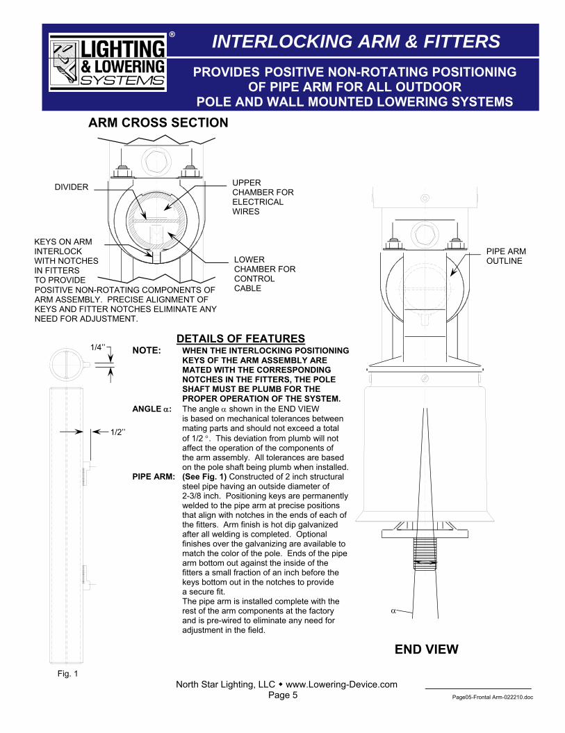
ARM CROSS SECTION
UPPER CHAMBER FOR ELECTRICAL WIRES
LOWER CHAMBER FOR CONTROL CABLE
DIVIDER
KEYS ON ARM INTERLOCK WITH NOTCHES IN FITTERS TO PROVIDE POSITIVE NON-ROTATING COMPONENTS OF ARM ASSEMBLY. PRECISE ALIGNMENT OF KEYS AND FITTER NOTCHES ELIMINATE ANY NEED FOR ADJUSTMENT.
DETAILS OF FEATURES NOTE: WHEN THE INTERLOCKING POSITIONING KEYS OF THE ARM ASSEMBLY ARE MATED WITH THE CORRESPONDING NOTCHES IN THE FITTERS, THE POLE SHAFT MUST BE PLUMB FOR THE PROPER OPERATION OF THE SYSTEM. ANGLE α: The angle α shown in the END VIEW is based on mechanical tolerances between mating parts and should not exceed a total of 1/2 °. This deviation from plumb will not affect the operation of the components of the arm assembly. All tolerances are based on the pole shaft being plumb when installed.PIPE ARM: (See Fig. 1) Constructed of 2 inch structural
steel pipe having an outside diameter of 2-3/8 inch. Positioning keys are permanently welded to the pipe arm at precise positions that align with notches in the ends of each of the fitters. Arm finish is hot dip galvanized after all welding is completed. Optional finishes over the galvanizing are available tomatch the color of the pole. Ends of the pipearm bottom out against the inside of the fitters a small fraction of an inch before the keys bottom out in the notches to provide a secure fit. The pipe arm is installed complete with the rest of the arm components at the factory and is pre-wired to eliminate any need for adjustment in the field.
Fig. 1
END VIEW
α
1/4’’
1/2’’
PIPE ARMOUTLINE
North Star Lighting, LLC www.Lowering-Device.com Page 5 Page05-Frontal Arm-022210.doc
®
PROVIDES POSITIVE NON-ROTATING POSITIONING OF PIPE ARM FOR ALL OUTDOOR
POLE AND WALL MOUNTED LOWERING SYSTEMS
INTERLOCKING ARM & FITTERS

®
North Star Lighting, LLC ♦ www.Lowering-Device.com Page 6 Page06-Comp Cord-3cond-020310.doc
SPECIFICATION SHEETComposite Cord # W-1
Composite Cord Specifications: Type: SEOOW 3-#14 AWG POWER CABLES (Green, White, and Black) Voltage Rating: 600V. Water & Sunlight Resistant SEOOW Jacket Temp. Rating for SOOW cord: 90ºC
(S) Hard Surface Flexible CordMaterial: Rubber Composite
(O) Oil Resistant Jacket
Three #14 AWG. Stranded Tinned Copper; Wire insulation colors: White/Black/Green Voltage Rating: 600V (O) Oil Resistant Conductor Wire Insulation Material: Rubber Composite
Fillers as required
North Star Lighting, LLC ♦ www.Lowering-Device.com Page 7
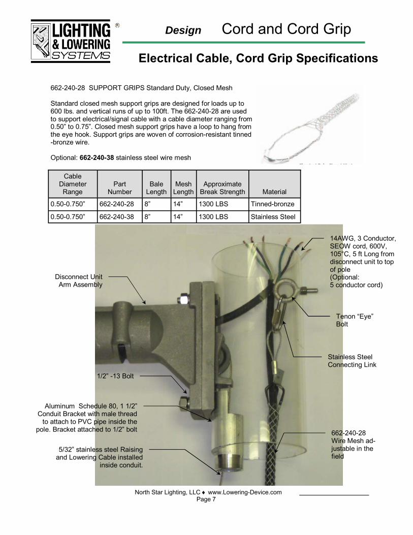
Design Cord and Cord Grip
Electrical Cable, Cord Grip Specifications
662-240-28 SUPPORT GRIPS Standard Duty, Closed Mesh Standard closed mesh support grips are designed for loads up to 600 lbs. and vertical runs of up to 100ft. The 662-240-28 are used to support electrical/signal cable with a cable diameter ranging from 0.50” to 0.75”. Closed mesh support grips have a loop to hang from the eye hook. Support grips are woven of corrosion-resistant tinned-bronze wire. Optional: 662-240-38 stainless steel wire mesh
Cable Diameter Range
Part
Number
Bale
Length
Mesh
Length
Approximate
Break Strength
0.50-0.750” 662-240-28 8” 14” 1300 LBS
Material
Tinned-bronze
0.50-0.750” 662-240-38 8” 14” 1300 LBS Stainless Steel
Disconnect Unit Arm Assembly
Tenon “Eye” Bolt
Stainless Steel Connecting Link
662-240-28 Wire Mesh ad-justable in the field
14AWG, 3 Conductor, SEOW cord, 600V, 105°C, 5 ft Long from disconnect unit to top of pole (Optional: 5 conductor cord)
5/32” stainless steel Raising and Lowering Cable installed
inside conduit.
Aluminum Schedule 80, 1 1/2” Conduit Bracket with male thread
to attach to PVC pipe inside the pole. Bracket attached to 1/2” bolt
1/2” -13 Bolt

Design WALL AND TOWER
Wind load Rating: 120mph (195kmph) w/1.3 Gust with 1.65 safety factor. Load Capacity: 200lbs (91kgs) with safety factor of 10 Total EPA: 3.00 Total Weight: 95 lbs (includes arm, disconnect unit, camera junction box, pole top junction box, and camera)
2 stainless steel locking cams suspending total weight of camera and camera Junction Box
5 5/8” (142.875mm) Dia. Disconnect Unit
37” (.94M)
12” (304.8mm)
9” (228.60mm) SQ. Junction Box (Optional) 10.5” (266.7mm)
1 ½” (38.1mm) Female Pipe Thread
2 3/8” O.D. (60.325mm) Galv. Divided Pipe
16” (406mm)
SIGNAL CABLE COMING OUT OF TOP OF CABINET
North Star Lighting, LLC www.Lowering-Device.comPage 8 Page08-ALS-arm & unit meas-092310.DOC
®
MOUNT MEASUREMENTS
835 Industrial Drive ♦ Elmhurst, IL 60126 ♦ PH: (708) 681-4330 ♦ Fax: (708) 681-4006 ♦ www.Lowering-Device.com Page 09 Page09-CAMJB-10-021815
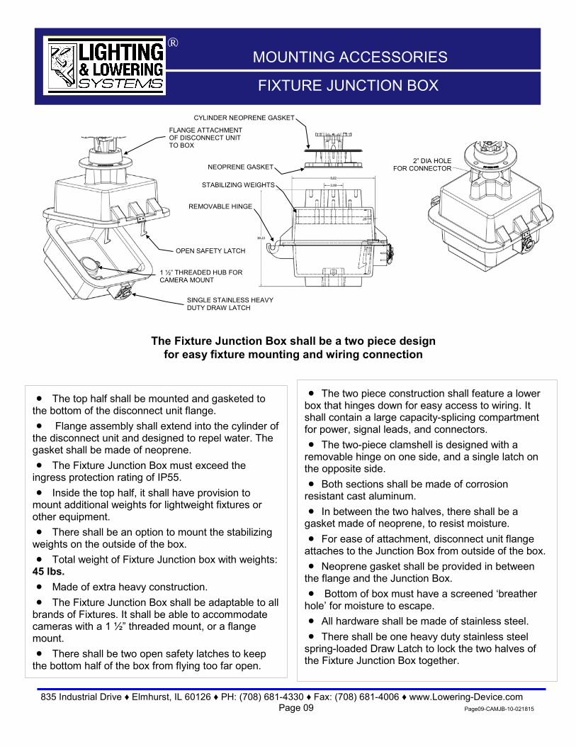
MOUNTING ACCESSORIES ®
FIXTURE JUNCTION BOX
FLANGE ATTACHMENT OF DISCONNECT UNIT TO BOX
SINGLE STAINLESS HEAVY DUTY DRAW LATCH
• The two piece construction shall feature a lower box that hinges down for easy access to wiring. It shall contain a large capacity-splicing compartment for power, signal leads, and connectors. • The two-piece clamshell is designed with a
removable hinge on one side, and a single latch on the opposite side. • Both sections shall be made of corrosion
resistant cast aluminum. • In between the two halves, there shall be a
gasket made of neoprene, to resist moisture. • For ease of attachment, disconnect unit flange
attaches to the Junction Box from outside of the box. • Neoprene gasket shall be provided in between
the flange and the Junction Box. • Bottom of box must have a screened ‘breather
hole’ for moisture to escape. • All hardware shall be made of stainless steel. • There shall be one heavy duty stainless steel
spring-loaded Draw Latch to lock the two halves of the Fixture Junction Box together.
• The top half shall be mounted and gasketed to the bottom of the disconnect unit flange. • Flange assembly shall extend into the cylinder of
the disconnect unit and designed to repel water. The gasket shall be made of neoprene. • The Fixture Junction Box must exceed the
ingress protection rating of IP55. • Inside the top half, it shall have provision to
mount additional weights for lightweight fixtures or other equipment. • There shall be an option to mount the stabilizing
weights on the outside of the box. • Total weight of Fixture Junction box with weights:
45 lbs. • Made of extra heavy construction. • The Fixture Junction Box shall be adaptable to all
brands of Fixtures. It shall be able to accommodate cameras with a 1 ½” threaded mount, or a flange mount. • There shall be two open safety latches to keep
the bottom half of the box from flying too far open.
REMOVABLE HINGE
1 ½” THREADED HUB FOR CAMERA MOUNT
OPEN SAFETY LATCH
STABILIZING WEIGHTS
2” DIA HOLE FOR CONNECTOR
The Fixture Junction Box shall be a two piece design for easy fixture mounting and wiring connection
NEOPRENE GASKET
CYLINDER NEOPRENE GASKET

Design ALS Aeronautical Lowering System
Guide Cable Instructions
North Star Lighting, LLC • www.Lowering-Device.com Page 10 P:\Donfile-120308\Specs\ALS-Misc\ALS-Guide Cable Instructions-092410.doc
®
Installation of Guide Cable The purpose of the Guide Cable is to guide the fixture down to the ground while being lowered. The cable keeps the fixture from possibly hitting the structure during heavy wind gusts. The taper of the mounting structure may also interfere in the fixture coming down. The angle of the guide cable will vary. The angle is determined by the diameter of the fixture and the taper of the structure. The angle must be equal to or greater than the taper of the structure. Also, the cable must be angled out far enough as to not touch the fixture. The smaller the fixture diameter, the smaller the angle can be.
1. Attach Tension Spring (By Others, One per fixture assembly) about 20° Max from fixture.
2. Attach Guide Cable Quick Link to Eyebolt on Disconnect Unit.
3. On other end of cable, slip through pulley on Fixture Guide.
4. Attach Turnbuckle to Tension Spring. 5. Attach Thimble to Turnbuckle. 6. Slip Guide Cable around Thimble and bring
short end of cable next to long end of cable. 7. Install U-bolt section of Wire Rope Clip on
short end of rope, and saddle on long end of rope and tighten nuts evenly. Apply first clip as near the thimble as possible. Apply second clip about one inch away from first clip.
8. Tape cable with electrical tape and cut extra cable in center of tape. On short end of cable, leave about one inch of cable from cable end to second clip.
9. A tension spring should be provided in each
guide cable to provide sufficient tension to hold guide cable taut (30-50 lbs) depending on length of guide cable. It must provide also sufficient movement for the sway of the structure (tower, stack, pole, and wall) under maximum wind load without exerting more than 150 lbs. tension on the guide cable. The brackets must be properly anchored and secured to withstand this load. Tension spring is not required if sway at top of structure is less than 6°, under maximum allowable wind load.
10. Mount fixture onto disconnect unit. Fixture must weigh at least 20 lbs. Add additional weights if necessary.
Guide Cable
Fixture Guide
Wire Rope Link
Turnbuckle
Thimble
Disconnect Unit Eyebolt
Tension Spring(By Others)
20°max.
1”
Second Clip
Thimble

North Star Lighting, LLC www.Lowering-Device.comPage 11 SLB-3-Wall Mount-060911.docx
HEAVY DUTY SECURITY LOCKING BOX MATERIAL: CORROSION FREE CAST ALUMINUM FINISH: ALUMINUM. OPTIONAL-POWDER COAT
PAINTED FINISH DOOR: CAST ALUMINUM DOOR WITH ATTACHED
HINGE, HINGING DOWNWARD. MOUNTING: BOX IS SIDE MOUNTED OR MOUNTED
FROM REAR OF THE BOX TO THE WALL. LOWERING TOOL: TO BE USED WITH A LT-4-XX
PORTABLE LOWERING TOOL. CONDUIT OPENING: OPENING IN TOP OF BOX FOR
1 ½” CONDUIT (REDUCER NEEDED FOR SMALLER CONDUIT).
GASKETED AROUND DOOR, PREVENTING WATER FROM PENETRATING.
SCREENED WEEP HOLE IN BOTTOM OF BOX FOR MOISTURE RELEASE.
PAD LOCKABLE DOOR TO BOX. PADLOCK BY OTHERS.
BOX DOOR ATTACHED TO THE BOX, HINGING DOWN WITH TOOL-LESS HARDWARE.
LARGE OPENING ALLOWS LOWERING TOOL TO BE ATTACHED TO THE BOX, WITH ROOM FOR SERVICING THE RAISING AND LOWERING CABLE.
EYEBOLT FOR RAISING AND LOWERING CABLE PARKING STAND LOCATED INSIDE OF BOX.
HEAVY DUTY STAINLESS STEEL OR GALV. STEEL MOUNTING BRACKET TO ATTACH TO POLE.
BOX OUTTER DIMENSIONS: 14”H x 6”W x 5”D DIMENSIONS WITH COVER: 14”H x 6”W x 6 1/8”D DIMPLES IN REAR OF BOX FOR WALL MOUNTING. DIMPLES DIMINSIONS: 2” WIDE X 9” HEIGHT. RECOMMENDED MOUNTING HARDWARE (NOT
INCLUDED): FOUR 3/8” BOLTS.
Security Box
1 ½” Conduit for Raising and Lowering cable
Cover
Eyebolt Cable Parking Stand
SIDE VIEW FRONTAL VIEW
Design SLB-3 for ALS SYSTEM WALL MOUNT Security Locking Box for Portable
Lowering Tool
6 1/8”
14”
6”
4 Dimples for Wall Mount drilling
®
LT-4-XX Lowering Tool (Order Separately).
835 Industrial Drive Elmhurst, IL 60126 Phone 708-681-4330 Fax 708-681-4006 www.lowering-device.com Page 12 Page12-LT4-082013
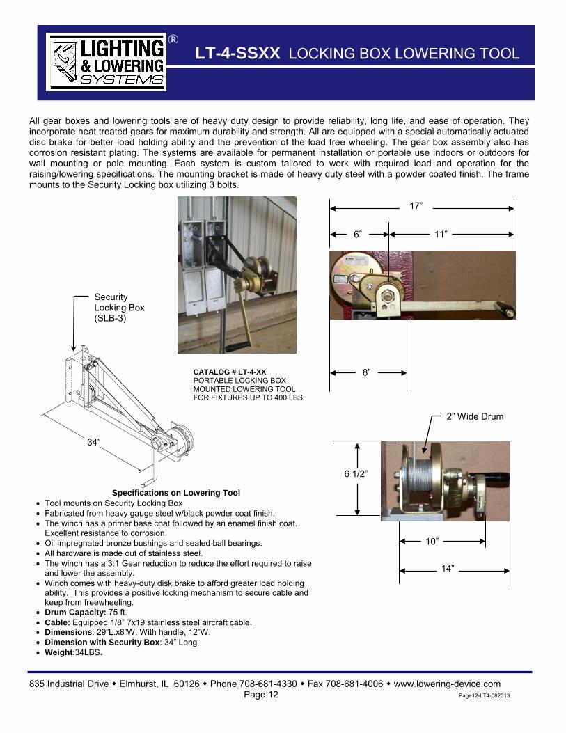
LT-4-SSXX LOCKING BOX LOWERING TOOL ®
All gear boxes and lowering tools are of heavy duty design to provide reliability, long life, and ease of operation. They incorporate heat treated gears for maximum durability and strength. All are equipped with a special automatically actuated disc brake for better load holding ability and the prevention of the load free wheeling. The gear box assembly also has corrosion resistant plating. The systems are available for permanent installation or portable use indoors or outdoors for wall mounting or pole mounting. Each system is custom tailored to work with required load and operation for the raising/lowering specifications. The mounting bracket is made of heavy duty steel with a powder coated finish. The frame mounts to the Security Locking box utilizing 3 bolts.
34”
6”
17”
11”
8”
2” Wide Drum
6 1/2”
10”
14”
Specifications on Lowering Tool • Tool mounts on Security Locking Box • Fabricated from heavy gauge steel w/black powder coat finish. • The winch has a primer base coat followed by an enamel finish coat.
Excellent resistance to corrosion. • Oil impregnated bronze bushings and sealed ball bearings. • All hardware is made out of stainless steel. • The winch has a 3:1 Gear reduction to reduce the effort required to raise
and lower the assembly. • Winch comes with heavy-duty disk brake to afford greater load holding
ability. This provides a positive locking mechanism to secure cable and keep from freewheeling.
• Drum Capacity: 75 ft. • Cable: Equipped 1/8” 7x19 stainless steel aircraft cable. • Dimensions: 29”L.x8”W. With handle, 12”W. • Dimension with Security Box: 34” Long • Weight:34LBS.
Security Locking Box (SLB-3)
CATALOG # LT-4-XX PORTABLE LOCKING BOX MOUNTED LOWERING TOOL FOR FIXTURES UP TO 400 LBS.
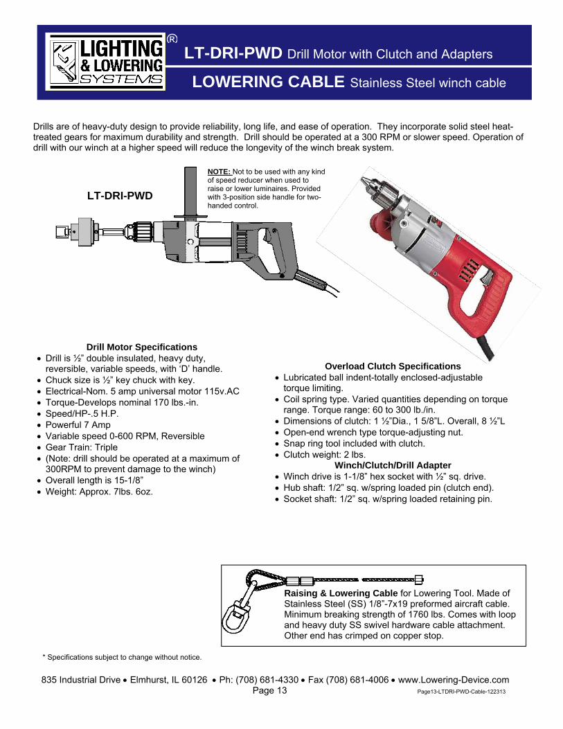
Drills are of heavy-duty design to provide reliability, long life, and ease of operation. They incorporate solid steel heat-treated gears for maximum durability and strength. Drill should be operated at a 300 RPM or slower speed. Operation of drill with our winch at a higher speed will reduce the longevity of the winch break system.
LT-DRI-PWD Drill Motor with Clutch and Adapters
* Specifications subject to change without notice.
835 Industrial Drive Elmhurst, IL 60126 Ph: (708) 681-4330 Fax (708) 681-4006 www.Lowering-Device.com Page 13 Page13-LTDRI-PWD-Cable-122313
LT-DRI-PWD
NOTE: Not to be used with any kind of speed reducer when used to raise or lower luminaires. Provided with 3-position side handle for two-handed control.
Drill Motor Specifications Drill is ½” double insulated, heavy duty,
reversible, variable speeds, with ‘D’ handle. Chuck size is ½” key chuck with key. Electrical-Nom. 5 amp universal motor 115v.AC Torque-Develops nominal 170 lbs.-in. Speed/HP-.5 H.P. Powerful 7 Amp Variable speed 0-600 RPM, Reversible Gear Train: Triple (Note: drill should be operated at a maximum of
300RPM to prevent damage to the winch) Overall length is 15-1/8” Weight: Approx. 7lbs. 6oz.
Raising & Lowering Cable for Lowering Tool. Made of Stainless Steel (SS) 1/8”-7x19 preformed aircraft cable. Minimum breaking strength of 1760 lbs. Comes with loop and heavy duty SS swivel hardware cable attachment. Other end has crimped on copper stop.
Overload Clutch Specifications Lubricated ball indent-totally enclosed-adjustable
torque limiting. Coil spring type. Varied quantities depending on torque
range. Torque range: 60 to 300 lb./in. Dimensions of clutch: 1 ½”Dia., 1 5/8”L. Overall, 8 ½”L Open-end wrench type torque-adjusting nut. Snap ring tool included with clutch. Clutch weight: 2 lbs.
Winch/Clutch/Drill Adapter Winch drive is 1-1/8” hex socket with ½” sq. drive. Hub shaft: 1/2” sq. w/spring loaded pin (clutch end). Socket shaft: 1/2” sq. w/spring loaded retaining pin.
®
LOWERING CABLE Stainless Steel winch cable