toyota 5fb10 forklift service repair manual
TRANSCRIPT
RETURN TO: MAIN INDEX
RETURN TO: SERVICE MANUAL INDEX
GENERAL
CONTROL CIRCUIT
MULTIDISPLAY FUNCTIONS
ELECTRICAL SYSTEM TROUBLESHOOTING
MATERIAL HANDLING SYSTEM
MAST
CYLINDERS
APPENDIX
5FB10-30
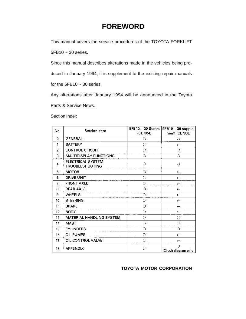
FOREWORD
TOYOTA MOTOR CORPORATION
This manual covers the service procedures of the TOYOTA FORKLIFT
5FB10 ~ 30 series.
Since this manual describes alterations made in the vehicles being pro-
duced in January 1994, it is supplement to the existing repair manuals
for the 5FB10 ~ 30 series.
Any alterations after January 1994 will be announced in the Toyota
Parts & Service News.
Section Index

0-2
EXTERIOR VIEWS

0-3
VEHICLE MODELS
FRAME NUMBER
0-4
HOW TO READ THIS MANUAL
EXPLANATION METHOD
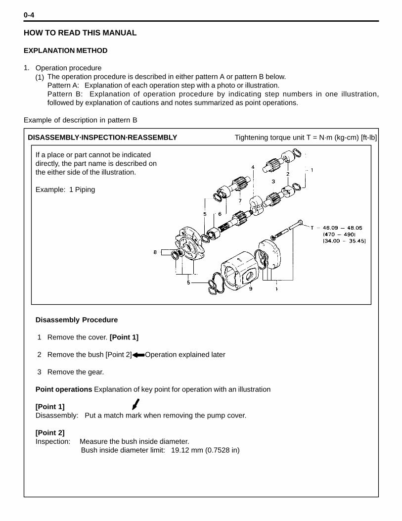
Operation procedureThe operation procedure is described in either pattern A or pattern B below.Pattern A: Explanation of each operation step with a photo or illustration.Pattern B: Explanation of operation procedure by indicating step numbers in one illustration,followed by explanation of cautions and notes summarized as point operations.
Example of description in pattern B
DISASSEMBLY·INSPECTION·REASSEMBLY Tightening torque unit T = N·m (kg-cm) [ft-lb]
If a place or part cannot be indicateddirectly, the part name is described onthe either side of the illustration.
Example: 1 Piping
Disassembly Procedure
Remove the cover. [Point 1]
Remove the bush [Point 2] Operation explained later
Remove the gear.
Point operations Explanation of key point for operation with an illustration
[Point 1]Disassembly: Put a match mark when removing the pump cover.
[Point 2]Inspection: Measure the bush inside diameter.
Bush inside diameter limit: 19.12 mm (0.7528 in)
1.(1)
1
2
3
0-5
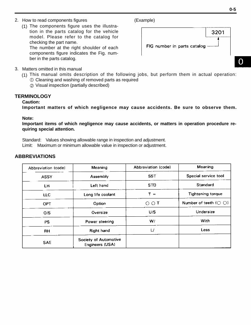
How to read components figures (Example)
Matters omitted in this manualThis manual omits description of the following jobs, but perform them in actual operation:
Cleaning and washing of removed parts as requiredVisual inspection (partially described)
TERMINOLOGYCaution:Important matters of which negligence may cause accidents. Be sure to observe them.
Note:Important items of which negligence may cause accidents, or matters in operation procedure re-quiring special attention.
Standard: Values showing allowable range in inspection and adjustment.Limit: Maximum or minimum allowable value in inspection or adjustment.
ABBREVIATIONS
The components figure uses the illustra-tion in the parts catalog for the vehiclemodel. Please refer to the catalog forchecking the part name.The number at the right shoulder of eachcomponents figure indicates the Fig. num-ber in the parts catalog.
2.
3.
(1)
(1)

0-6
CIRCUIT TESTER
Circuit testers are available in both the analog and digital types. They should be used selectively ac-cording to the purpose of measurement.Analog type: This type is convenient for observing movement during operation, but the measured
value should only be used for reference or rough judgment.
Digital type: Fairly accurate reading is possible, but it is difficult to observe the variation or move-ment.
Difference in measurement results with the digital type and analog typeThe result may be different between measurements with the analog type and digital type. Al-ways use a circuit tester according to its operation manual. Cautions when the polarities are dif-ferent between the analog type and digital type are described below.
Circuit tester range: Analog type kohm range Digital type 2 Mohm range
Forward direction Reverse direction
Measurement result example
As seen from the example above, the measurement results with the analog and digital types are re-verse. In measurement with a digital type circuit tester, therefore, use the tester probes as shown be-low.
Forward direction Reverse direction
1.*
0-7
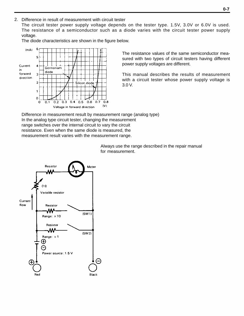
Difference in result of measurement with circuit testerThe circuit tester power supply voltage depends on the tester type. 1.5V, 3.0V or 6.0V is used.The resistance of a semiconductor such as a diode varies with the circuit tester power supplyvoltage.The diode characteristics are shown in the figure below.
Difference in measurement result by measurement range (analog type)In the analog type circuit tester, changing the measurementrange switches over the internal circuit to vary the circuitresistance. Even when the same diode is measured, themeasurement result varies with the measurement range.
Always use the range described in the repair manualfor measurement.
2.
The resistance values of the same semiconductor mea-sured with two types of circuit testers having differentpower supply voltages are different.
This manual describes the results of measurementwith a circuit tester whose power supply voltage is3.0 V.
0-8
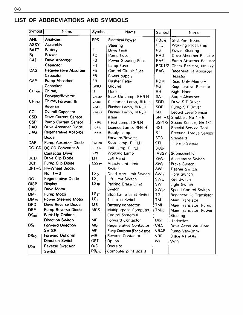
LIST OF ABBREVIATIONS AND SYMBOLS
0-9
OPERATIONAL TIPS
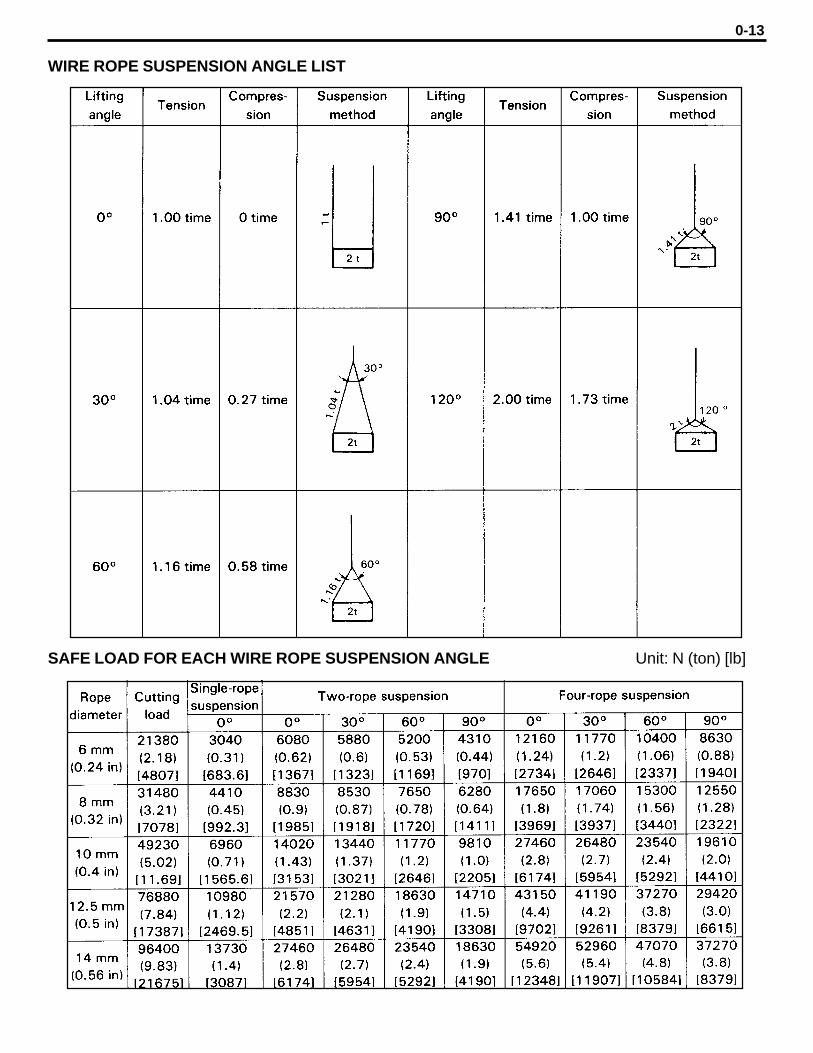
Safe operationAfter jacking up, always support with rigid stands.When hoisting the vehicle or its heavy component, use wire repe(s) with a sufficient reserve inload capacity.Always disconnect the battery plugs before the inspection or servicing of electrical parts.
Tactful operationPrepare the mechanic tools, necessary measuring instruments (circuit tester, megger, oil pres-sure gauge, etc.) and SSTs before starting operation.Before disconnecting wiring, always check the cable color and wiring state.When overhauling functional parts, complicated portions or related mechanisms, arrange the partsneatly to prevent confusion.When disassembling and inspecting such a precision part as the control valve, use clean toolsand operate in a clean location.Follow the described procedures for disassembly, inspection and reassembly.Replace, gaskets, packings and O-rings with new ones each time they are disassembled.Use genuine Toyota parts for replacement.Use specified bolts and nuts. Observe the specified tightening torque at the time of reassembly.If no tightening torque is specified, tighten the bolt or nut according to the standard tighteningtorque table.
Grasping the trouble stateWhen a trouble occurs, do not attempt immediate disassembly or replacement but first check ifthe trouble requires disassembly or replacement for remadying.
1.
2.
3.
(1)(2)
(3)
(1)
(2)(3)
(4)
(5)(6)(7)(8)
0-10
STANDARD BOLT & NUT TIGHTENING TORQUE
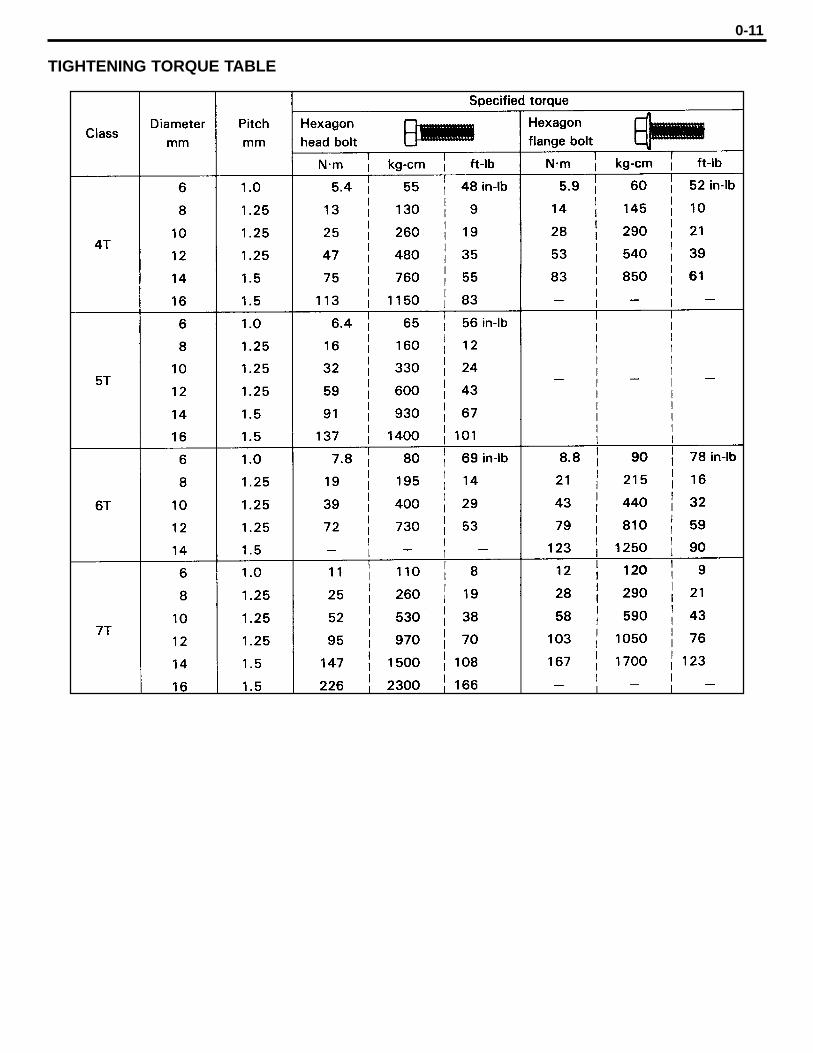
Standard bolt and tightening torques are not indicated.Judge the standard tightening torque as shown below.
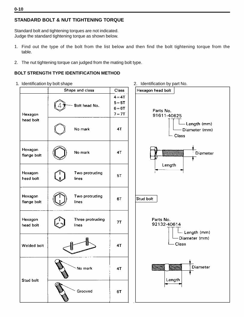
Find out the type of the bolt from the list below and then find the bolt tightening torque from thetable.
The nut tightening torque can judged from the mating bolt type.
BOLT STRENGTH TYPE IDENTIFICATION METHOD
Identification by bolt shape 2. Identification by part No.
1.
2.
1.
0-11
TIGHTENING TORQUE TABLE

0-12
HIGH PRESSURE HOSE FITTING TIGHTENING TORQUE
When connecting a high pressure hose, wipe the hose fitting and mating nipple contact surfaceswith clean cloth to remove foreign matters and dirt. Also check no dent or other damage on thecontact surfaces before installation.When connecting a high pressure hose, hold the hose to align the fitting with the nipple andtighten the fitting.The maximum tightening torque must not exceed twice the standard tightening torque.
PRECOAT BOLTS
(Bolts with seal lock agent coating on threads)
Do not use the precoat bolt as it is in either of the fol-lowing cases.
After is removed.When the precoat bolt is moved (loosened or tight-ened) by tightness check, etc.
Note:For torque check, use the lower limit of the allowable tight-ening torque range. If the bolt moves, retighten it accordingto the steps below.
Method for reuse of precoat boltsWash the bolt and threaded hole. (The threaded holemust be washed even for replacement of the bolt.)Perfectly dry the washed parts by air blowing.Coat the specified seal lock agent to the threadedportion of the bolt.
1.
2.
(a)(b)
(1)
(2)(3)
1.
2.
3.
0-13
WIRE ROPE SUSPENSION ANGLE LIST
SAFE LOAD FOR EACH WIRE ROPE SUSPENSION ANGLE Unit: N (ton) [lb]
0-14
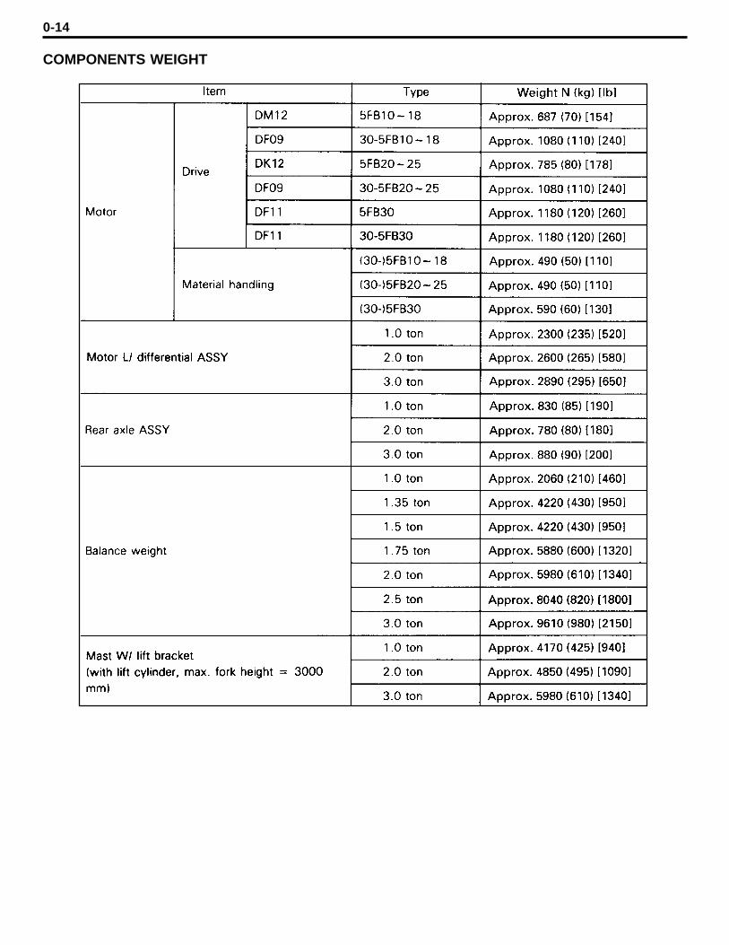
COMPONENTS WEIGHT
0-15
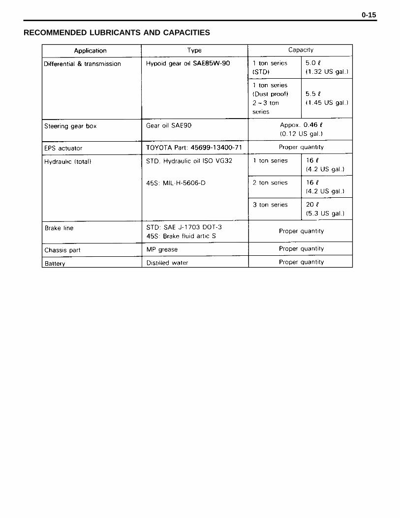
RECOMMENDED LUBRICANTS AND CAPACITIES
0-16
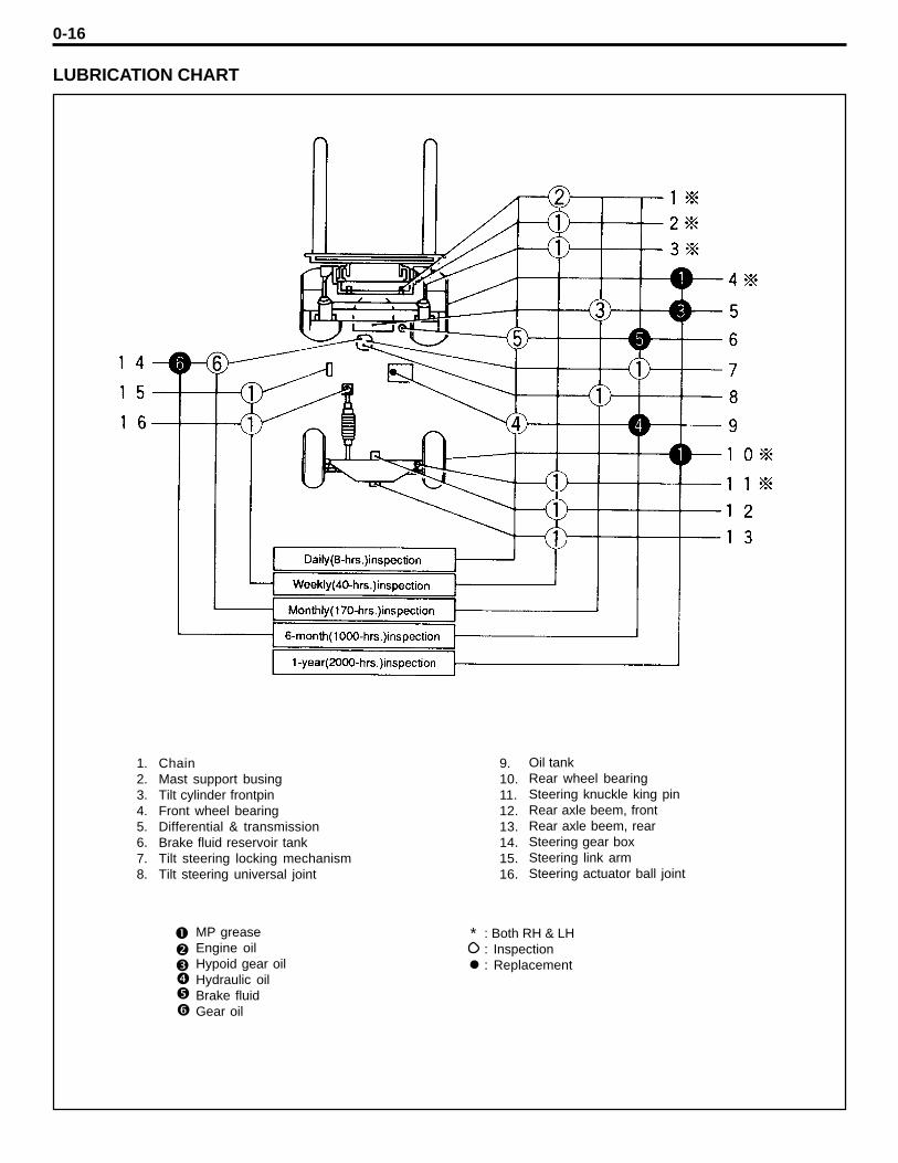
LUBRICATION CHART
ChainMast support busingTilt cylinder frontpinFront wheel bearingDifferential & transmissionBrake fluid reservoir tankTilt steering locking mechanismTilt steering universal joint
Oil tankRear wheel bearingSteering knuckle king pinRear axle beem, frontRear axle beem, rearSteering gear boxSteering link armSteering actuator ball joint
1.2.3.4.5.6.7.8.
9.10.11.12.13.14.15.16.
MP greaseEngine oilHypoid gear oilHydraulic oilBrake fluidGear oil
: Both RH & LH: Inspection: Replacement
*
l
0-17
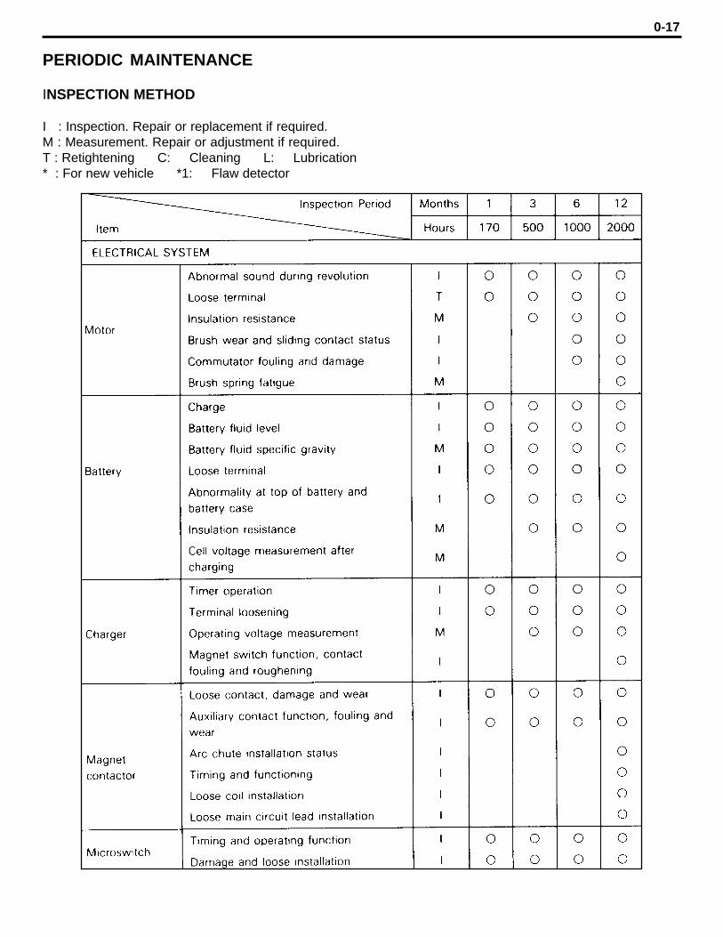
PERIODIC MAINTENANCE
INSPECTION METHOD
I : Inspection. Repair or replacement if required.M : Measurement. Repair or adjustment if required.T : Retightening C: Cleaning L: Lubrication* : For new vehicle *1: Flaw detector
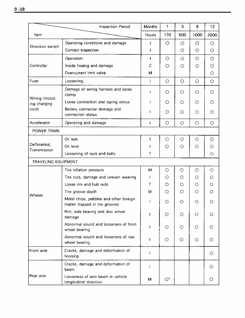
0 -18
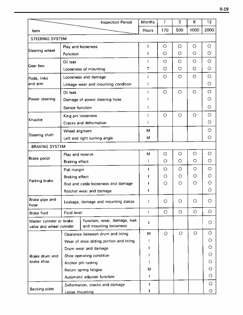
0-19

0-20

0-21
0-22
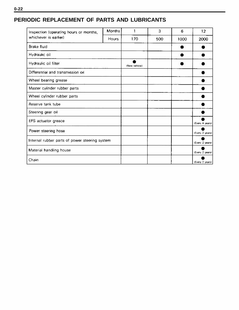
PERIODIC REPLACEMENT OF PARTS AND LUBRICANTS
2-2
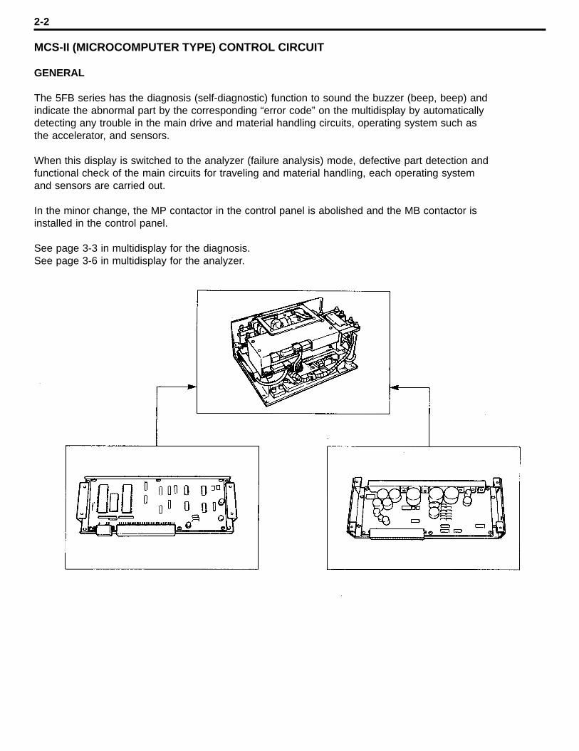
MCS-II (MICROCOMPUTER TYPE) CONTROL CIRCUIT
GENERAL
The 5FB series has the diagnosis (self-diagnostic) function to sound the buzzer (beep, beep) andindicate the abnormal part by the corresponding “error code” on the multidisplay by automaticallydetecting any trouble in the main drive and material handling circuits, operating system such asthe accelerator, and sensors.
When this display is switched to the analyzer (failure analysis) mode, defective part detection andfunctional check of the main circuits for traveling and material handling, each operating systemand sensors are carried out.
In the minor change, the MP contactor in the control panel is abolished and the MB contactor isinstalled in the control panel.
See page 3-3 in multidisplay for the diagnosis.See page 3-6 in multidisplay for the analyzer.
2-3
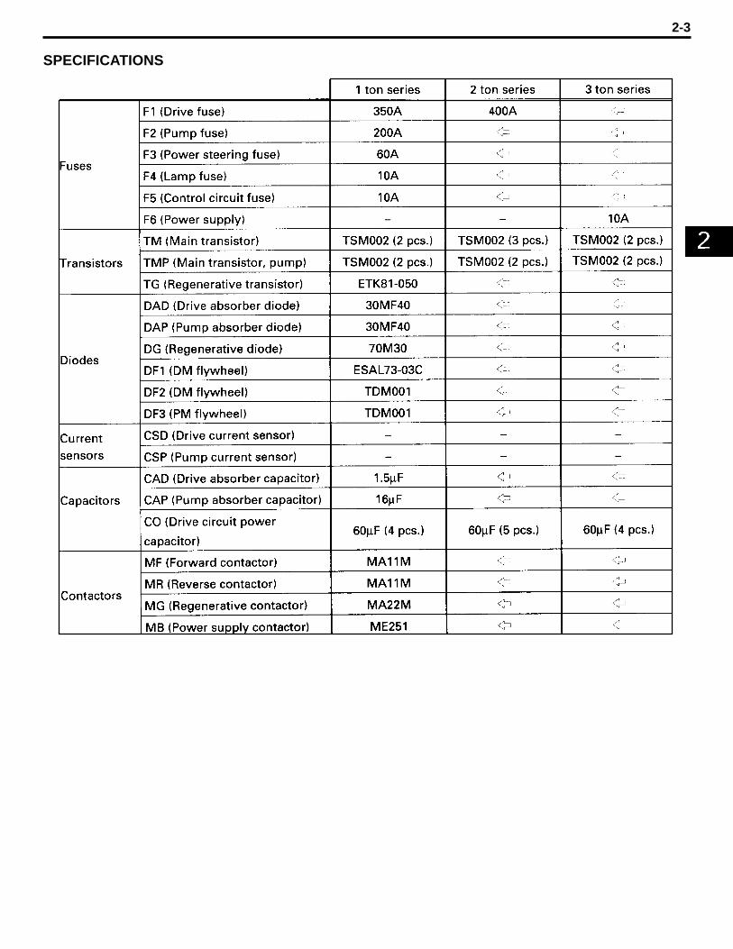
SPECIFICATIONS
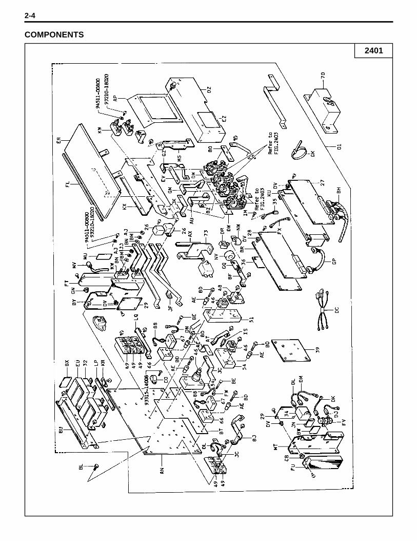
COMPONENTS
2-4
2401
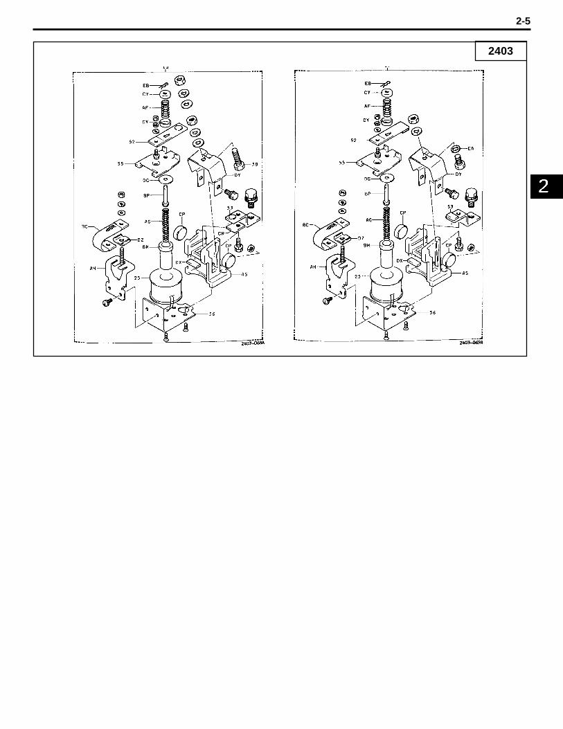
2403
2-5
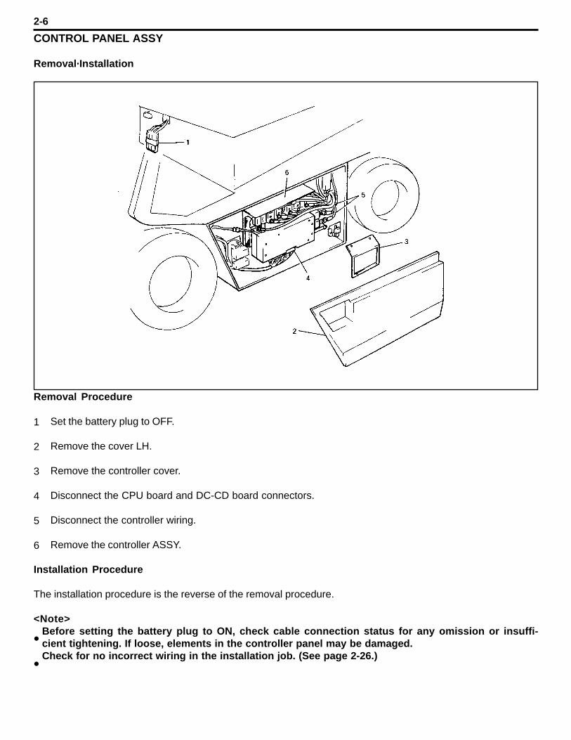
CONTROL PANEL ASSY
Removal·Installation
Removal Procedure
Set the battery plug to OFF.
Remove the cover LH.
Remove the controller cover.
Disconnect the CPU board and DC-CD board connectors.
Disconnect the controller wiring.
Remove the controller ASSY.
Installation Procedure
The installation procedure is the reverse of the removal procedure.
<Note>Before setting the battery plug to ON, check cable connection status for any omission or insuffi-cient tightening. If loose, elements in the controller panel may be damaged.Check for no incorrect wiring in the installation job. (See page 2-26.)
2-6
l
l
1
2
3
4
5
6

Inspection
Some components can be inspected without removal from the vehicle while other componentsrequire removal before inspection.The CPU board and DC-CD board are inspected on the vehicle because battery voltage applicationis necessary. (Use SST 09240-13200-71 or SST 09240-23400-71.)The description here is mainly for inspection after removing control panel from the vehicle.
Insulation resistance measurement (always inspect the insulation resistance before startingcontrol panel inspection.)
Set the battery plug to off and measure the insulation resistance between the battery plugwire harness and body.
2-7
1.
(1)
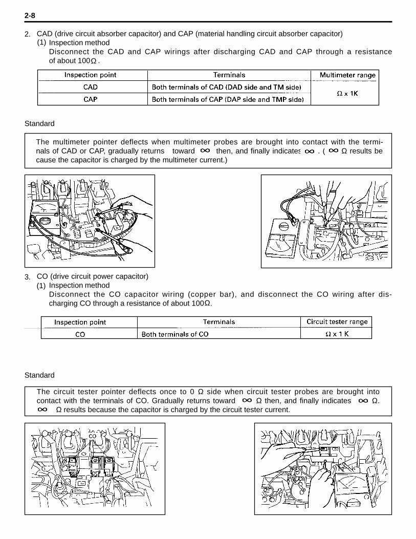
CAD (drive circuit absorber capacitor) and CAP (material handling circuit absorber capacitor)Inspection methodDisconnect the CAD and CAP wirings after discharging CAD and CAP through a resistanceof about 100 .
Standard
CO (drive circuit power capacitor)Inspection methodDisconnect the CO capacitor wiring (copper bar), and disconnect the CO wiring after dis-charging CO through a resistance of about 100 .
Standard
2-8
Ω
Ω
2.(1)
The multimeter pointer deflects when multimeter probes are brought into contact with the termi-nals of CAD or CAP, gradually returns toward then, and finally indicates . ( Ω results because the capacitor is charged by the multimeter current.)
3.(1)
The circuit tester pointer deflects once to 0 Ω side when circuit tester probes are brought intocontact with the terminals of CO. Gradually returns toward Ω then, and finally indicates Ω. Ω results because the capacitor is charged by the circuit tester current.
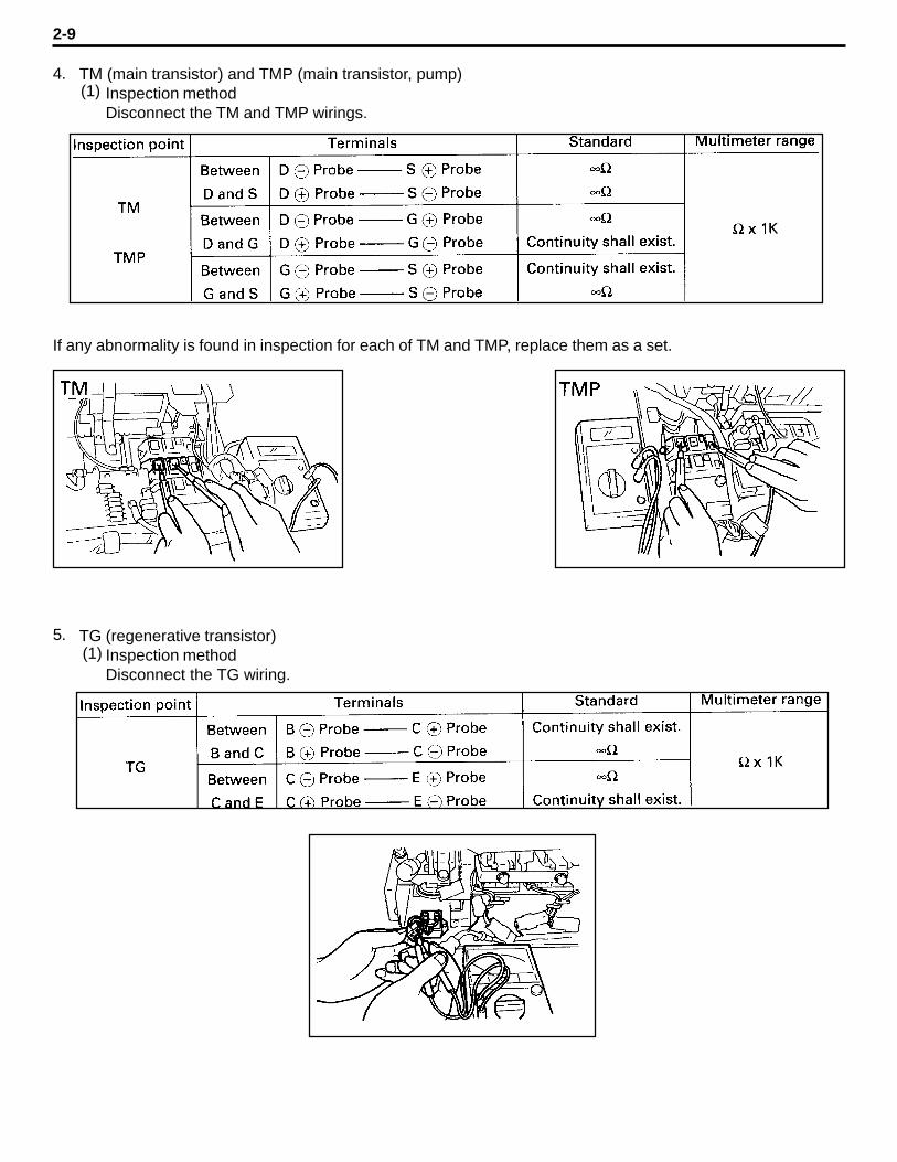
TM (main transistor) and TMP (main transistor, pump)Inspection methodDisconnect the TM and TMP wirings.
If any abnormality is found in inspection for each of TM and TMP, replace them as a set.
TG (regenerative transistor)Inspection methodDisconnect the TG wiring.
2-9
4.(1)
5.(1)
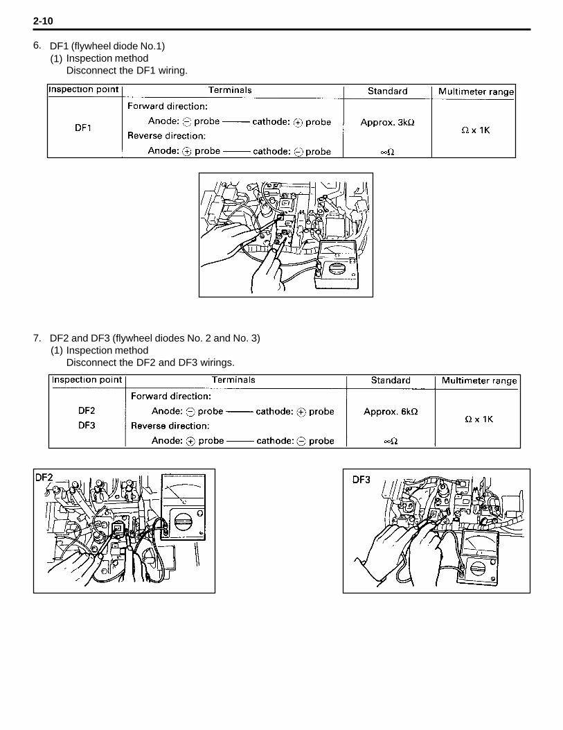
DF1 (flywheel diode No.1)Inspection methodDisconnect the DF1 wiring.
DF2 and DF3 (flywheel diodes No. 2 and No. 3)Inspection methodDisconnect the DF2 and DF3 wirings.
2-10
6.(1)
7.(1)
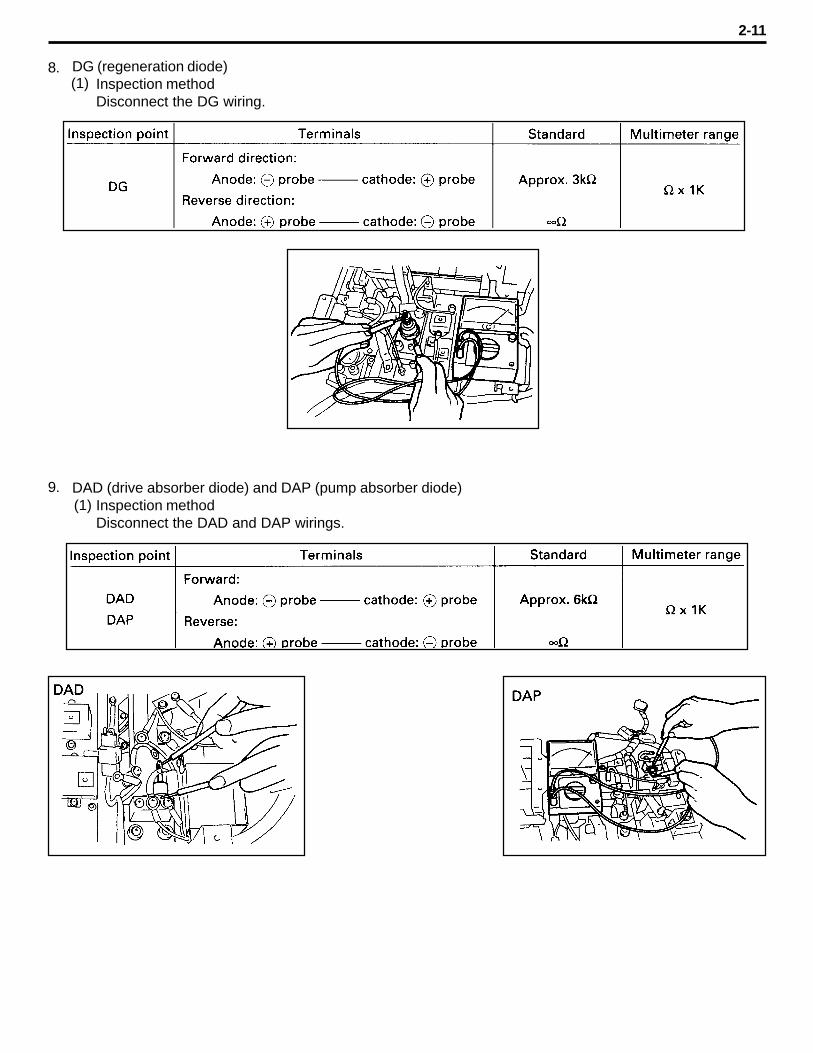
DG (regeneration diode)Inspection methodDisconnect the DG wiring.
DAD (drive absorber diode) and DAP (pump absorber diode)Inspection methodDisconnect the DAD and DAP wirings.
2-11
8.(1)
9.(1)
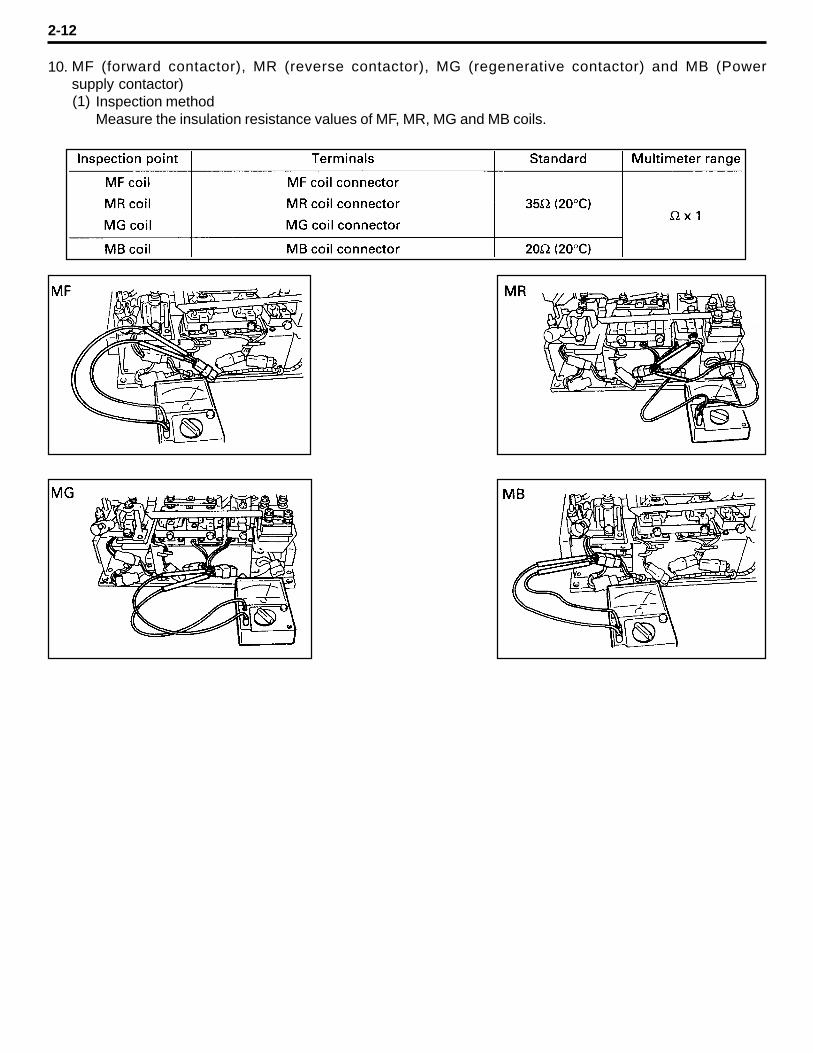
MF (forward contactor), MR (reverse contactor), MG (regenerative contactor) and MB (Powersupply contactor)
Inspection methodMeasure the insulation resistance values of MF, MR, MG and MB coils.
2-12
10.
(1)
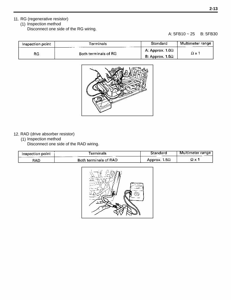
RG (regenerative resistor)Inspection methodDisconnect one side of the RG wiring.
A: 5FB10 ~ 25 B: 5FB30
RAD (drive absorber resistor)Inspection methodDisconnect one side of the RAD wiring.
2-13
11.(1)
12.(1)
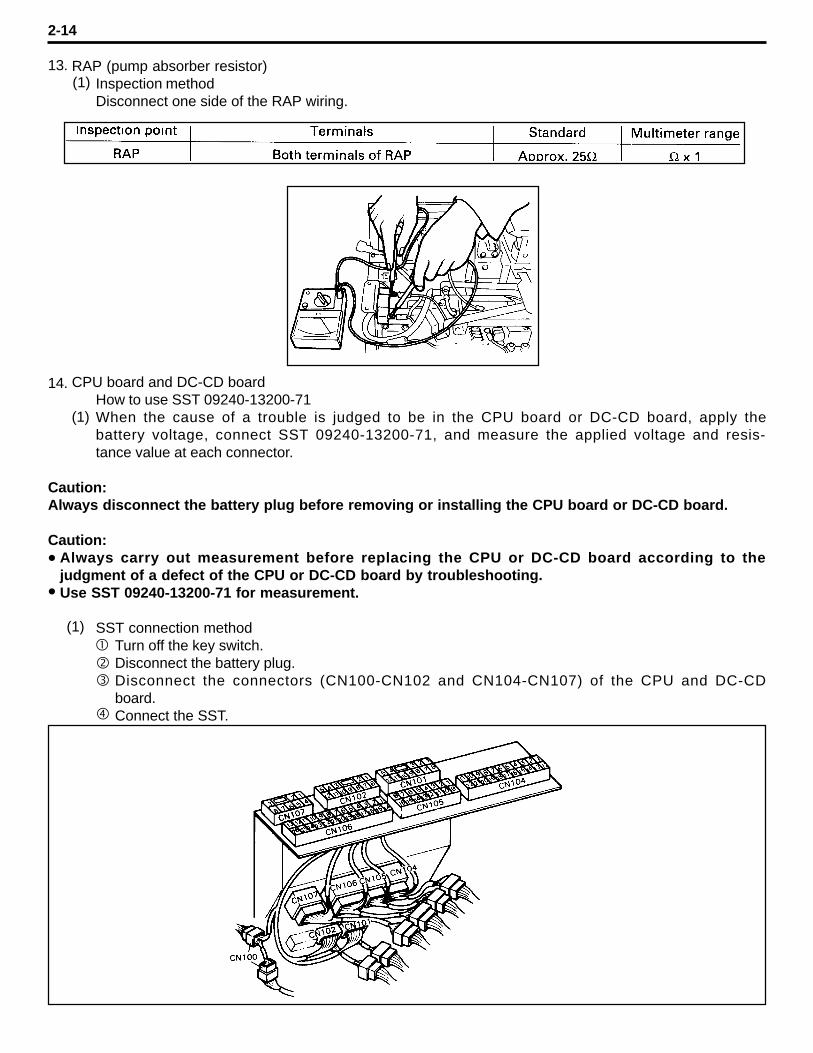
RAP (pump absorber resistor)Inspection methodDisconnect one side of the RAP wiring.
CPU board and DC-CD boardHow to use SST 09240-13200-71When the cause of a trouble is judged to be in the CPU board or DC-CD board, apply thebattery voltage, connect SST 09240-13200-71, and measure the applied voltage and resis-tance value at each connector.
Caution:Always disconnect the battery plug before removing or installing the CPU board or DC-CD board.
Caution:Always carry out measurement before replacing the CPU or DC-CD board according to thejudgment of a defect of the CPU or DC-CD board by troubleshooting.Use SST 09240-13200-71 for measurement.
SST connection methodTurn off the key switch.Disconnect the battery plug.Disconnect the connectors (CN100-CN102 and CN104-CN107) of the CPU and DC-CDboard.Connect the SST.
2-14
l
l
13.(1)
14.
(1)
(1)
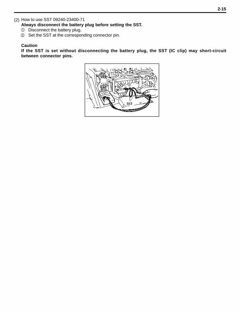
How to use SST 09240-23400-71Always disconnect the battery plug before setting the SST.
Disconnect the battery plug.Set the SST at the corresponding connector pin.
CautionIf the SST is set without disconnecting the battery plug, the SST (IC clip) may short-circuitbetween connector pins.
2-15
(2)
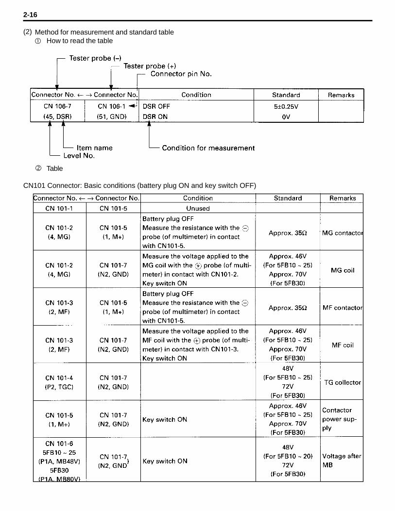
Method for measurement and standard tableHow to read the table
Table
CN101 Connector: Basic conditions (battery plug ON and key switch OFF)
2-16
(2)
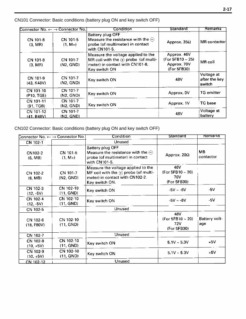
CN101 Connector: Basic conditions (battery plug ON and key switch OFF)
2-17
CN102 Connector: Basic conditions (battery plug ON and key switch OFF)
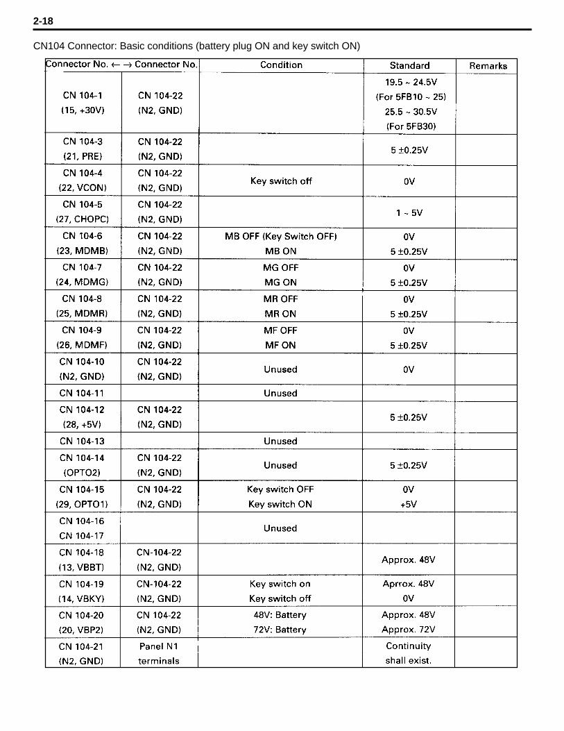
CN104 Connector: Basic conditions (battery plug ON and key switch ON)
2-18
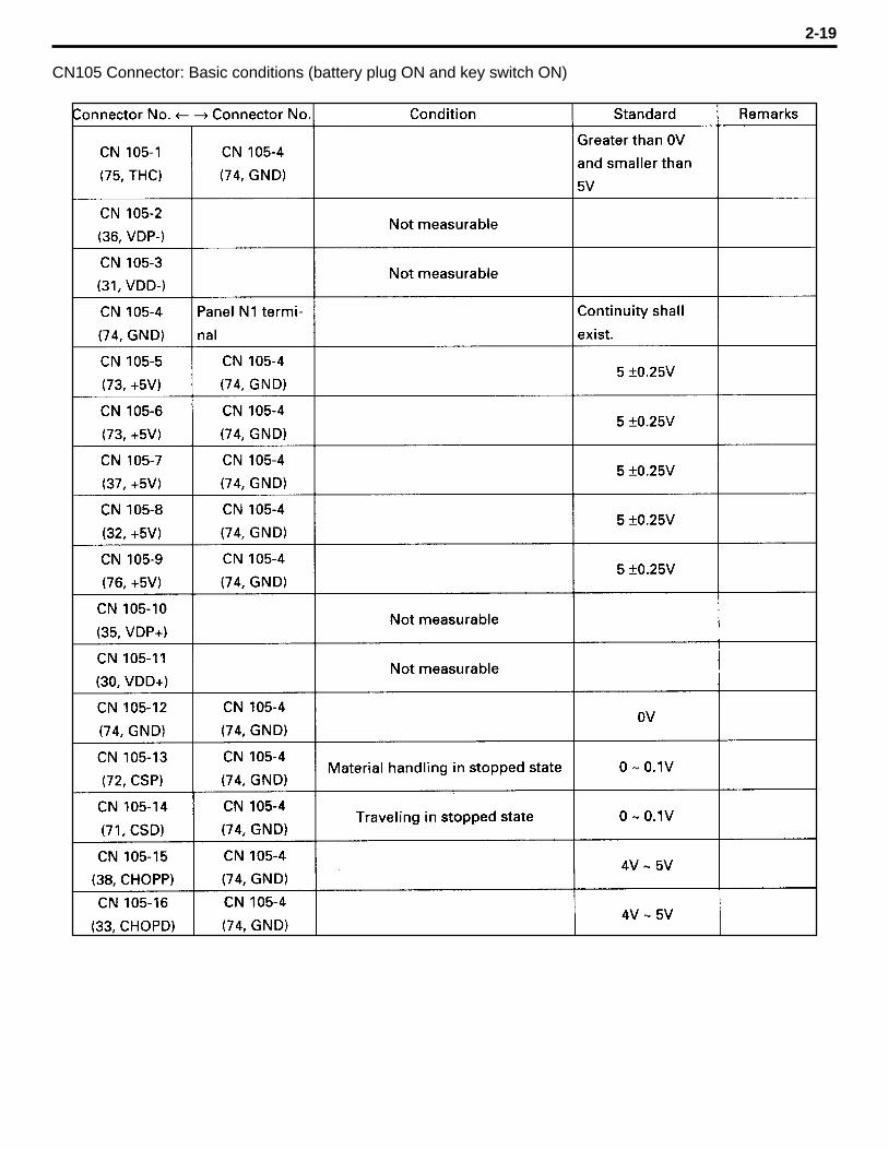
CN105 Connector: Basic conditions (battery plug ON and key switch ON)
2-19

CN106 Connector: Basic conditions (battery plug ON and key switch ON)
2-20
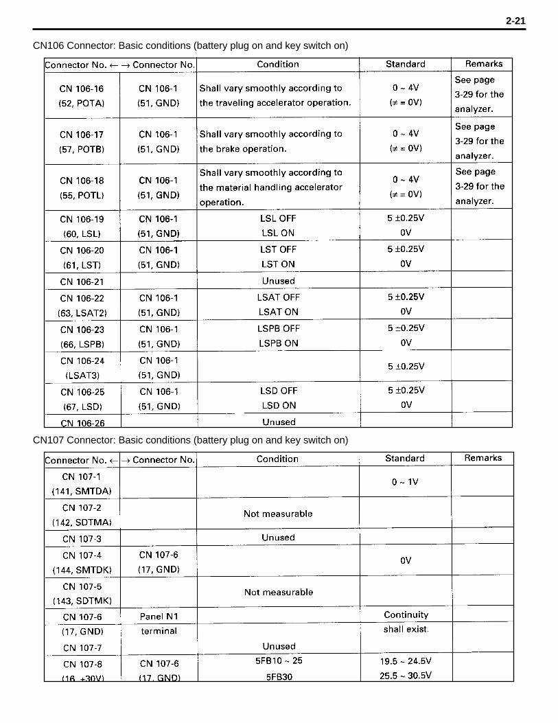
CN106 Connector: Basic conditions (battery plug on and key switch on)
2-21
CN107 Connector: Basic conditions (battery plug on and key switch on)

DisplayWhen the cause of a trouble is judged to exist in the display, apply the battery voltage andmeasure the voltages applied to each connector.
CN120 Connector: Basic condition (battery plug on)
2-22
15.
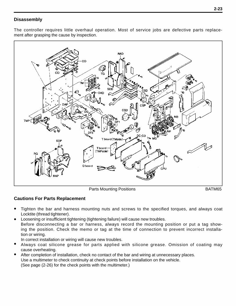
Disassembly
The controller requires little overhaul operation. Most of service jobs are defective parts replace-ment after grasping the cause by inspection.
Cautions For Parts Replacement
Tighten the bar and harness mounting nuts and screws to the specified torques, and always coatLocktite (thread tightener).Loosening or insufficient tightening (tightening failure) will cause new troubles.Before disconnecting a bar or harness, always record the mounting position or put a tag show-ing the position. Check the memo or tag at the time of connection to prevent incorrect installa-tion or wiring.In correct installation or wiring will cause new troubles.Always coat silicone grease for parts applied with silicone grease. Omission of coating maycause overheating.After completion of installation, check no contact of the bar and wiring at unnecessary places.Use a multimeter to check continuity at check points before installation on the vehicle.(See page (2-26) for the check points with the multimeter.)
2-23
l
l
l
l
Parts Mounting Positions BATM65

Thank you very much for your reading.
Please Click Here Then Get More Information.