toyota motor sales, u.s.a., inc. 19001 south western ... · 19001 south western avenue, s207...
TRANSCRIPT

TMS-NTC-14022 February 26, 2014
Toyota Motor Sales, U.S.A., Inc. 19001 South Western Avenue, S207 Torrance, CA 90509-2991
Recall Management Division National Highway Traffic Safety Administration 1200 New Jersey Avenue, SE Washington, DC 20590 Re: Toyota Safety Recall 13V-396 Dealer Notification (Remedy) To whom it may concern, Please find attached the Dealer Notification Letter (Remedy) for Toyota Safety Recall 13V-396 on the following Toyota and Lexus vehicles:
• Certain 2006 through 2010 Model Year Highlander HV • Certain 2006 to 2008 Model Year RX 400h
If you have any questions regarding this matter, please contact me at (310) 468-5316. Sincerely,
Quality Compliance Assistant Manager Attachments:
• Toyota 13V-396 (D0M) Dealer Notification (Remedy) • Lexus 13V-396 (DLF) Dealer Notification (Remedy)

To: All Toyota Dealer Principals, Service Managers, and Parts Managers
Subject: Safety Recall D0M – Remedy Available Certain 2006 through 2010 Model Year Highlander Hybrid Vehicles Intelligent Power Module (IPM) Replacement
As previously announced on September 3, 2013, Toyota filed a Defect Information Report (DIR) with the National Highway Traffic Safety Administration (NHTSA) informing the agency of our intent to conduct a voluntary Safety Recall on Certain 2006 through 2010 Model Year Highlander Hybrid Vehicles.
Toyota has completed remedy preparations and will now begin mailing the remedy owner letter.
Condition
Inside the Hybrid Inverter Assembly is an Intelligent Power Module (IPM) which contains a control board equipped with transistors. Due to variations in operating characteristics of some IPM transistors, the temperature of the transistor(s) can exceed the allowable temperature of the solder underneath the transistor. If this occurs, the solder could degrade and eventually cause heat damage to the transistor(s), illuminating various warning lights on the instrument panel. In most cases, the vehicle will enter a “fail-safe” mode, resulting in reduced power under which the vehicle can still be driven for short distances. In limited cases, the fuse of the power supply circuit could blow, causing the hybrid system to shut down. If the Hybrid System shuts down, the vehicle could stop while being driven increasing the risk of crash.
Remedy
Toyota dealers will replace the IPM at NO CHARGE to the vehicle owner. For additional information on repair procedures, please refer to TIS.
The following information is provided to inform you of the owner notification timing and your degree of involvement.
1. Owner Letter Mailing Date
Toyota has completed remedy preparations and will begin to notify owners in mid-October, 2013. A sample of the owner notification letter has been included for your reference.
Toyota tries very hard to obtain current customer name and address information when mailing owner letters. In the event your dealership receives a notice for a vehicle that was sold prior to the Safety Recall announcement, it is the dealership’s responsibility to forward the owner letter to the customer who purchased the vehicle.
Please note that only owners of the covered vehicles will be notified. If a dealer is contacted by an owner who has not yet received the notification, please instruct the dealer to verify coverage by confirming through TIS. Dealers should perform the procedure as outlined in the Technical Instructions located on TIS.
2. Dealer/Owner Lists
Summary Reports, containing the number of covered vehicles in your dealership’s primary marketing area, have been enclosed in the dealer package. (Please verify eligibility by confirming through Dealer Daily or TIS prior to performing repairs.)
3. Pre-Owned Vehicles in Dealer Stock
Toyota requests that dealers verify whether their Pre-Owned vehicles in dealer inventory are covered by this Safety Recall. If a vehicle is covered, the dealer should perform the Safety Recall remedy prior to customer delivery.

Safety Recall D0M – D – Page 2
4. Number and Identification of Covered Vehicles There are approximately 79,600 Toyota Highlander Hybrid covered by this Safety Recall in the U.S.
Model Name Model Year Production Period Number of Vehicles Toyota
Highlander Hybrid Certain 2006 through 2010 Mid February 2005 through late July 2010
Approximately 79,600 units
Please note that only owners of the covered vehicles will be notified. If your dealership is contacted by an owner who has not yet received the notification, please instruct the dealer to verify coverage by confirming through TIS. Dealers should perform the procedure as outlined in the Technical Instructions located on TIS. A UIO matrix by state is provided to inform your dealership of the number of covered vehicles in your state. STATE UIO STATE UIO STATE UIO STATE UIO STATE UIO
AK 266 HI 105 MI 1041 NV 586 UT 866AL 474 IA 615 MN 1515 NY 4090 VA 3583AR 323 ID 463 MO 934 OH 1588 VT 326AZ 1459 IL 3108 MS 181 OK 439 WA 3997CA 14990 IN 1003 MT 325 OR 2093 WI 1209CO 3822 KS 556 NC 2018 PA 2772 WV 247CT 1400 KY 631 ND 82 RI 285 WY 157DC 307 LA 347 NE 321 SC 663 DE 195 MA 2995 NH 573 SD 167 FL 2941 MD 2094 NJ 2193 TN 1000 GA 1427 ME 436 NM 739 TX 3484
5. Parts Ordering Process Orders can be placed through the dealership’s facing PDC. The kits have been placed on Dealer Ordering Solutions and will be systematically released daily based on dealer ordering criteria. Please refer to the table below and the Technical Instructions for part ordering information.
Model Application Part No. Part Name Qty/Unit
Highlander HV 04001-29148 TRANSISTER, PWR MODULE INTELLIGENT, NO.2 1 08887-02409 GREASE G747 2
IMPORTANT PARTS ORDERING UPDATE All Safety Recall, Service Campaign (SSC/LSC) and Customer Support Program (CSP) parts will be eligible for the Monthly Parts Return Program. Please refer to PANT Bulletin 2011-087 for campaign parts that are
currently returnable under the Monthly Parts Return Program and additional details.
6. Technician Training Requirements
The repair quality of covered vehicles is extremely important to Toyota. All dealership associates involved in the recall process are required to successfully complete E-Learning course SC13A. To ensure that all vehicles have the repair performed correctly; technicians performing this recall repair are required to have the following minimum certification:
• Hybrid Expert • Master Technician • Master Diagnostic Specialist
It is the dealership’s responsibility to select technicians with the above certification level or greater to perform this Safety Recall repair. Carefully review your resources, the technician skill level, and ability before assigning technicians to this repair. It is important to consider technician days off and vacation schedules to ensure there are properly trained technicians available to perform this repair at all times.

Safety Recall D0M – D – Page 3 7. Remedy Procedures
Please refer to TIS for Technical Instructions on repair.
Conduct all applicable, non-completed Safety Recall and Service Campaigns on the vehicle during the time of appointment.
8. Campaign Special Service Tools
In a separate shipment scheduled to arrive October 2, 2013, your dealership was sent a package containing special service tools for this campaign. When received, the package will have a fluorescent (green, orange, yellow, or pink) label like the sample shown below for easy identification.
Part Name Sample Qty Part Name Sample Qty
Protective Cover A
1 Protective Cover B 1
Masking Plate 1 Squeegee 1
Stud Bolt 2 Masking Plate Nut/Bolt
4
NOTE: If additional gloves are needed they can be ordered through SPX by calling 800-933-8335 (Gloves are not included in the Campaign Tool Kit)
Part Number Part Name Quantity
00002-03100-S Electrical Insulating Gloves (Small) 1 00002-03200-M Electrical Insulating Gloves (Medium)
00002-03300-L Electrical Insulating Gloves (Large)
ATTN: Service Manager SAFETY RECALL D0M
Campaign Tools

9. Warranty Reimbursement Procedure
Certain 2006 through 2010 Model Year Highlander Hybrid Vehicles
• The flat rate times include 0.1 hours for administrative cost per unit for the dealership. • Toyota Genuine Brake Cleaner and Toyota Genuine Throttle Plate Cleaner or equivalent can be
claimed as sublet type “OF” under OP Code 3530HJ, 3530HM or 3530HQ at a rate of $5.00 per vehicle(marking pens and electrical tape is also included in the sublet cost)
• Parts replaced under OP code 3530HJ, 3530HM or 3530HQ are subject to warranty parts return, any misuse of these operation codes will result in a warranty claim debit
Safety Recall
Op. Code Description Flat Rate
Hour
D0M Contact Region Rep.
Replace the IPM, DTC present after IPM replacement, replace Inverter Assembly on 2WD Models DW21A & GW21A
Contact Region Rep.
Replace the IPM, DTC present after IPM replacement, replace Inverter Assembly on AWD Models EW21A & HW21A
Contact Region Rep.
Replace the IPM, DTC present after IPM replacement, replace Inverter Assembly on AWD Models BW3EH, EW41A, EW44A & JW3EH
Contact Region Rep.
• Regional representative will provide available sublets for this operation
Important Note: If you have DTCs Present after performing the IPM replacement, please consult the Technical Instruction Appendix and repair manual for DTC diagnosis. In the event you need further assistance diagnosing the current DTCs, please contact the Technical Assistance Hotline – QA Powertrain Department at 800-233-3178. Do not file a claim for Intelligent Power Module replacement; you will need to obtain an Op. Code from your regional representative for Inverter Replacement.
Model Op. Code Description Flat Rate
Hour
06 - 07 MY 2WD 3530HJ Replace the IPM for 2WD models (DW21A & GW21A) 3.4 hr/vehicle
06 - 07 MY AWD 3530HM Replace the IPM for AWD models (EW21A & HW21A) 3.5 hr/vehicle
08 – 10 MY 3530HQ Replace the IPM for AWD models (BW3EH, EW41A, EW44A & JW3EH) 4.0 hr/vehicle

Safety Recall D0M – D – Page 5
Campaign Designation Decoder
Examples: A0D = Launched in 2010, Remedy Phase, 4th Campaign Launched in 2010 B1M = Launched in 2011, Interim Phase, 13th Campaign Launched in 2011 D0B = Launched in 2012, Remedy Phase, 1st Campaign Launched in 2013
10. Repair Quality Confirmation
The repair quality of covered vehicles is extremely important to Toyota. To help ensure that all vehicles have the repair performed correctly, please designate at least one associate (someone other than the individual who performed the repair) to verify the repair quality of every vehicle prior to customer delivery.
11. Media Contacts
If you are a dealership associate and have any questions, please contact your District Service/Parts Manager. In the event you are contacted by the News media, it is imperative that all media contacts (local and national) receive a consistent message. In this regard, all media contacts must be directed to Cindy Knight (310) 468-2170 in Toyota Corporate Communications. (Please do not provide this number to customers)
12. Customer Contacts
A FAQ is attached to help respond to any customer concerns. If the customer has any further questions, they are requested to contact the Toyota Customer Experience Center. The Toyota Customer Experience Center can be reached at 1-888-270-9371 Monday through Friday, 5:00 am to 6:00 pm, or Saturday 7:00 am through 4:00 pm Pacific Time.
Please note the attached FAQ is published on the www.Toyota.com website for customer viewing.
Please review this entire package with your Service and Parts staff to familiarize them with the proper step-by-step procedures required to implement this Safety Recall.
Thank you for your cooperation. TOYOTA MOTOR SALES, U.S.A., INC.

Page 1 of 3 © 2013 Toyota Motor Sales, USA
Safety Recall D0M - Remedy Available Certain 2006 through 2010 Model Year Highlander Hybrid Vehicles Intelligent Power Module (IPM) Replacement Background As previously announced on September 4, 2013, Toyota filed a Defect Information Report (DIR) with the National Highway Traffic Safety Administration (NHTSA) informing the agency of our intent to conduct a voluntary Safety Recall on certain 2006 through 2010 model year Highlander Hybrid vehicles. Toyota has completed remedy preparations and will now begin to notify owners. Q1: What is the condition? A1: Inside the hybrid inverter assembly is an Intelligent Power Module (IPM) which contains a control board
equipped with transistors. Due to variation in characteristics of transistors in parallel circuits, the temperature of the transistor(s) can exceed the allowable temperature of the solder underneath the transistor. If this occurs, the solder could degrade and eventually cause heat damage to the transistor(s), illuminating various warning lights on the instrument panel. In most cases, the vehicle will enter a “fail-safe” mode, resulting in reduced power under which the vehicle can still be driven for short distances. In limited instances, the fuse of the power supply circuit could blow, causing the hybrid system to shut down and resulting in the vehicle stopping while being driven. This can increase the risk of a crash.
Q1a: What is the Hybrid System Inverter? A1a: The hybrid system inverter converts high-voltage DC, stored in the HV battery, into AC for the motor
generator. It also converts AC into DC during regenerative braking for storage in the HV battery. Q2: Which Warning Lamps are illuminated on the instrument panel when the vehicle enters fail-safe
driving mode? A2: All of the following warning lights and messages will be illuminated on the instrument panel when the vehicle
enters the fail-safe driving mode. The fail-safe driving mode will result in reduced power under which the vehicle can still be driven for short distances.
Warning lights Warning messages
Master Warning Light Malfunction of VSC function is
detected.
Slip Indicator Hybrid system malfunction is
detected.
Check Engine Warning Light
All Wheel Drive system malfunction is detected.
(yellow indicator)
Electronically Controlled Brake System Warning Light
Customer Frequently Asked Questions Published Late September, 2013

Page 2 of 3 © 2013 Toyota Motor Sales, USA
Q2a: How long and what distance can a vehicle be driven when the vehicle enters fail-safe driving
mode? A2a: The distance a vehicle will continue to travel in fail-safe driving mode will vary based upon the
hybrid battery state of charge and the road conditions. If a vehicle enters fail-safe driving mode, the driver should pull-over and stop the car in a safe area. The driver should immediately contact his/her local Toyota dealer for assistance.
Q3: What is Toyota going to do? A3: In mid-October, 2013 Toyota will send an owner notification by first class mail to owners of vehicles
covered by this Safety Recall. Any authorized Toyota dealer will replace the Intelligent Power Module at No Charge to you.
Q3a: How does Toyota obtain my mailing information? A3a: Toyota uses an industry provider who works with each state’s Department of Motor Vehicles (DMV)
to receive registration or title information, based upon the DMV records. Please make sure your registration or title information is correct.
Q3b: Do I need my owner letter to have the remedy performed? A23b: You do not need an owner letter to have this recall completed; however, to assist the dealer in
confirming vehicle eligibility, we request that you present this notice at the time of your service appointment.
Q4: What steps can I take to reduce the possibility of this condition from occurring prior to the
availability of the remedy? A4: You can take the following steps to reduce the possibility of this condition from occurring until the remedy is
completed.
Inverter Coolant Reservoir
(1) Regularly confirm that the coolant level in the inverter coolant reservoir is between FULL and LOW. If the coolant level is below the LOW line, please add coolant up to the FULL line.
Toyota dealers will inspect the coolant level, and if necessary, add coolant, at no charge at the customer’s request.
Power Meter
(2) Avoid placing a high load on the Hybrid System. Drivers can do so by refraining from towing with the vehicle until the remedy is completed.
(3) Monitor your Power Meter. The Power Meter indicates the immediate output from the Hybrid System in approximate kilowatts. Keep power usage below 100kW as much as possible. Situations where the Power Meter shows output slightly over 100kW for a brief moment should not raise any concerns.

Page 3 of 3 © 2013 Toyota Motor Sales, USA
Q4a: Will this condition occur if the Power Meter shows usage above 100kW? A4a: Situations where the Power Meter shows output slightly over 100kW for a brief moment should not
raise any concerns. Drivers should refrain from driving conditions where power output exceeds 100kW continuously and/or substantially. Drivers can do so by refraining from towing with the vehicle until the remedy is completed.
Q5: Which and how many vehicles are covered? A5: There are approximately 79,600 Toyota Highlander Hybrid and approximately 53,500 Lexus RX 400h
vehicles covered by this Safety Recall in the U.S.
Model Name Model Year Production Period Number of VehiclesToyota
Highlander Hybrid Certain 2006 through 2010 Mid February 2005 through late July 2010
Approximately 79,600 units
Lexus RX 400h Certain 2006 through 2008Late February 2005
through early December 2008
Approximately 53,500 units
Q5a: Are there any other Toyota or Lexus models covered by this Safety Recall? A5a: No. There are no other Toyota or Lexus models covered by this Safety Recall.
Q6: What if my vehicle was covered by the previous Safety Recall (B0J) for 2006 and 2007 Model Year
Highlander Hybrid (HV) Vehicles Hybrid System Inverter, Intelligent Power Module? A6: If you have not had Safety Recall B0J performed, please contact any authorized Toyota dealer to schedule
an appointment to have the remedy performed as soon as possible. Q7: What if I previously paid for repairs to my vehicle for this condition? A7: Reimbursement consideration instruction will be provided in the remedy owner letter. Q8: What if I have additional questions or concerns? A8: If you have additional questions or concerns, please contact the Toyota Customer Experience Center at 1-
888-270-9371 Monday through Friday, 5:00 am to 6:00 pm, or Saturday 7:00 am through 4:00 pm Pacific Time.

SAMPLECertain 2006 through 2010 Model Year Highlander Hybrid (HV) Vehicles
Hybrid System Inverter, Intelligent Power Module IMPORTANT SAFETY RECALL
This notice applies to your vehicle: [VIN]
Dear Toyota Customer:
This notice is being sent to you in accordance with the requirements of the National Traffic and Motor Vehicle Safety Act. Toyota has decided that a defect, which relates to motor vehicle safety, exists in certain 2006 through 2010 Model Year Highlander Hybrid (HV) Vehicles.
You received this notice because our records, which are based primarily on state registration and title data, indicate that you are the current owner.
What is the condition?
Inside the hybrid inverter assembly is an Intelligent Power Module (IPM) which contains a control board equipped with transistors. Under some conditions, one or more transistors could be damaged, illuminating various warning lights on the instrument panel. In most cases, the vehicle will enter a “fail-safe” mode, resulting in reduced power under which the vehicle can still be driven for short distances. However, it is possible that the fuse of the power supply circuit could blow, causing the hybrid system to shut down and resulting in the vehicle stopping while being driven. This can increase the risk of a crash.
What is Toyota going to do?
Any authorized Toyota dealer will replace the IPM at NO CHARGE to you.
What should you do?
This is an important Safety Recall
Please contact any authorized Toyota dealer and make an appointment to have the IPM replaced. Replacement of the IPM will take approximately 4 hours. However, depending upon the dealer’s work schedule, it may be necessary to make your vehicle available for a longer period of time.
You do not need an owner letter to have this recall completed; however, to assist the dealer in confirming vehicle eligibility, we request that you present this notice at the time of your service appointment.
If you would like to update your vehicle ownership or contact information, please go to www.toyota.com/ownersupdate. You will need your full 17-digit Vehicle Identification Number (VIN) to input the new information.
What if you have other questions?
Your local Toyota dealer will be more than happy to answer any of your questions. If you require further assistance, you may contact Toyota Customer Experience Center at 1-888-270-9371 Monday through Friday, 5:00 am to 6:00 pm, Saturday 7:00 am through 4:00 pm Pacific Time.
If you believe that the dealer or Toyota has failed or is unable to remedy the defect within a reasonable time, you may submit a complaint to the Administrator, National Highway Traffic Safety Administration, 1200 New Jersey Avenue S.E., Washington, D.C. 20590, or call the toll free Vehicle Safety Hot Line at 1-888-327-4236 (TTY: 1-800-424-9153), or go to http://www.safercar.gov.
URGENT SAFETY RECALL This is an important Safety Recall. The remedy
will be performed at NO CHARGE to you.

SAMPLE
What if you have previously paid for repairs to your vehicle for this specific condition?
If you have previously paid for repair to your vehicle for this specific condition prior to receiving this letter, please mail a copy of your repair order and proof-of-payment to the following address for reimbursement consideration:
Toyota Motor Sales, U.S.A., Inc Toyota Customer Experience, WC 10
19001 South Western Avenue Torrance, CA 90509
Include your name, address, and telephone number(s) in your request. Please allow us 6-8 weeks to process your request.
Please note the dealership will need to complete the Safety Recall remedy before reimbursement consideration requests can be processed.
If you are a vehicle lessor, Federal law requires that any vehicle lessor receiving this recall notice must forward a copy of this notice to the lessee within ten days.
We have sent this notice in the interest of your continued satisfaction with our products, and we sincerely regret any inconvenience this condition may have caused you.
Thank you for driving a Toyota.
Sincerely,
TOYOTA MOTOR SALES, U.S.A., INC.

TECHNICAL INSTRUCTIONS
FOR
SAFETY RECALL D0M
INTELLIGENT POWER MODULE TRANSISTOR REPLACEMENT
CERTAIN 2006 ‒ 2010 MODEL YEAR HIGHLANDER HV
Complete D0M Technical Video Supplement
In order to perform this campaign, technician must be Hybrid Certified. If you have questions regarding certification, contact your regional representative.

I. OPERATION FLOW CHART
The flow chart is for reference only. DO NOT use it in place of the full technical instructions. Follow ALL steps as outlined in the full technical instructions to confirm the campaign is completed correctly.
Verify Vehicle Eligibility1. Check the VIN range.
2. Check the TIS Vehicle Inquiry System.
No further action required.Not Involved
Involved
Campaign complete.Return the vehicle to the customer.
Replace the Intelligent Power Module (IPM) Transistor.
Confirm and record any DTCs that may be present.
Confirm any DTCs that may be present. Use the repair manual and
the troubleshooting table in the Appendix section of the technical
instructions to diagnose.
2

II. BACKGROUND
Within the vehicle, inside the inverter assembly is an Intelligent Power Module (IPM) which contains a control board equipped with transistors. The solder underneath these transistors could degrade and eventually cause damage to them, illuminating various warning lights on the instrument panel. In most cases, the vehicle will enter a fail-safe mode, resulting in reduced motive power in which the vehicle can still be driven for short distances. In limited instances, the fuse of the power supply circuit could blow, causing the hybrid system to shut down and resulting in the vehicle stopping while being driven.
III. IDENTIFICATION OF AFFECTED VEHICLES
A. COVERED VIN RANGE
WMI Year VIN Range
VDS Range
JTE
2006
DW21A 0001012-0016473 EW21A 0001057-0033951 GW21A 0001612-0012447 HW21A 0015069-0015069
2007
DW21A 0016509-0023446 EW21A 0033956-0050060 GW21A 0016487-0023445 HW21A 0033954-0050064
2008 EW41A 2000108-2025890 EW44A 2000110-2025892
2009 EW41A 2025893-2037770 EW44A 2025894-2037778
2010 BW3EH 2037781-2048439 JW3EH 2037352-2048651
NOTE: • Check the TIS Vehicle Inquiry System to confirm the VIN is involved in this Safety Recall, and that the
campaign has not already been completed prior to dealer shipment or by another dealer. • TMS warranty will not reimburse dealers for repairs conducted on vehicles that are not affected or were
completed by another dealer.
3

IV. PREPARATION
A. PARTS
Required Parts – Necessary to complete the repair Part Number Part Description Quantity 04001-29148 Intelligent Power Module Transistor 1 08887-02409 Grease G747 2
Ancillary Parts – Only necessary if lost during the repair Part Description Part Number Part Description Part Number
91551-80610
90105-A0263
90105-A0096
90080-11255
91551-80614
B. TOOLS, SUPPLIES & EQUIPMENT
• Standard hand tools • Torque wrench • Techstream • Brake cleaner
• Marking pen • Air gun • Throttle plate cleaner 00289-1TP00
(or equivalent)
• Insulating tape • DVOM
SST – These are essential special service tools that the dealership should have. Part Number Part Name Quantity
00002-03100-S Electrical Insulating Gloves (Small) 1 00002-03200-M Electrical Insulating Gloves (Medium)
00002-03300-L Electrical Insulating Gloves (Large) NOTE: If additional gloves are needed they can be ordered through SPX by calling 800-933-8335
Campaign Tools – These tools are provided to the dealership. Part Name Sample Quantity Part Name Sample Quantity
Protective Cover A
1
Protective Cover B
1
Masking Plate
1
Squeegee
1
Stud Bolt
2 Masking Plate
Nut/Bolt 4
4

V. SAFETY PRECAUTIONS
A. SAFETY CHECKLIST & PRECAUTIONS WHEN WORKING ON THE HIGH VOLTAGE SYSTEM
• Always remember “SAFETY FIRST” • Be extremely careful when handling high voltage components • Before beginning and while working on the high voltage system, perform the following safety
check list.
1. AIR VENTILATION AND FOREIGN MATERIALS
Perform work in an area that is free of dust and other airborne matter. Do not perform the work next to a stall where grinding or spraying of chemicals is performed. When not working in the inverter, temporarily install the inverter cover to prevent foreign material entering the inverter.
2. PREVENT STATIC ELECTRICITY Static electricity can have an adverse effect on inverter components, discharge static electricity by touching a ground location on the vehicle before starting work.
3. PREVENT ELECTRICAL SHOCKS & SHORTS Confirm the auxiliary battery and the service grip have been unplugged for at least 5 minutes before beginning work on the high voltage system. Store the service grip in a secure location (in your pocket) to prevent accidental installation. To prevent short-circuiting of components, wrap tools with insulating tape before use. Do not wear metal; watches, rings, mechanical pencils, etc… When working with or around a high voltage circuit (orange connectors and cables) wear the correct electrical insulating gloves. Confirm your electrical insulating gloves are not wet, or dirty. Confirm your electrical insulating gloves are not punctured or torn.
4. USE OF AIR & POWER TOOLS Do not use air tools or power tools on any component once the inverter cover has been removed to prevent damage and foreign materials from entering the inverter.
5. HANDLING OF PARTS Keep all removed parts organized and clean. Store all removed parts so they are not contaminated or damaged when removed from the inverter.
6. HANDLING OF THE INVERTER & CONNECTORS Cover all high voltage connectors with insulating tape immediately after disconnecting the connector. Use extreme care to prevent nuts/bolts from falling into the inverter when work is performed. If a part falls into the bottom section of the inverter the entire inverter assembly may need to be removed. Use extreme care to not drop any tools in the inverter assembly.
7. CONNECTING HIGH VOLTAGE TERMINALS Confirm all terminals are clean before connecting to the inverter. Torque specifications are critical, confirm all bolts are torque as described in these instructions.
8. INTERMEDIATE INSPECTIONS Perform all intermediate inspections to prevent errors.
9. ASSIGN A SAFETY SUPERVISOR Assign a safety supervisor to be in charge of all safety precautions in the work area. Put a “Working with high voltage” warning sign on the vehicle during work.
5

6

VI. DISASSEMBLY
A. 06‒07MY - COMPONENTS
7

B. 08‒10MY - COMPONENTS
8

TORQUE SPECIFICATIONS INSIDE THE INVERTER ARE CRITICAL CONFIRM ALL BOLTS ARE TORQUED AS OUTLINED IN THESE INSTRUCTIONS
INTERNAL COMPONENTS IN THE INVERTER ARE NOT AVAILABLE AS SERVICE PARTS BE CAREFUL WHEN REMOVING, STORING, AND REINSTALLING THESE COMPONENTS
9

C. VEHICLE DISASSEMBLY ‒ There are some slight differences in vehicle disassembly between 06-07MY and 08-10MY, unique steps will be identified in these instructions.
• It is extremely important that all of the vehicle disassembly steps are followed prior to proceeding to the inverter disassembly steps. Failure to follow all steps could result in inverter damage.
• It is extremely important to prevent contamination of the inverter assembly. Confirm the work area is clean and free from airborne matter.
1. DETERMINE THE WORK PLACE
a) Choose a spot that is free of dust and debris. DO NOT work next to a place where grinding or spraying of chemicals is performed.
2. PLACE THE PROVIDED CAUTION SIGN ON THE ROOF OF THE VEHICLE
3. RECORD AUDIO AND AIR CONDITIONING SYSTEM SETTINGS
4. CHECK FOR DIAGNOSTIC TROUBLE CODES a) If any DTCs are output record the data.
5. DISCONNECT THE NEGATIVE BATTERY CABLE
6. REMOVE THE SERVICE GRIP
06-07MY
a) Disengage the 4 claws and 2 clips and remove the rear door scuff plate.
b) Disengage the 2 clips and the service grip access cover.
c) Wearing insulating gloves, remove the service grip.
08-10MY
a) Disengage the 2 claws and 3 clips and remove the rear door scuff plate.
b) Disengage the 2 clips and the service grip access cover.
c) Wearing insulating gloves, remove the service grip.
• Store the service grip in a secure location (in your pocket) to prevent accidental installation. • After removing the service grip, wait at least 5 minutes before working on the high voltage
system. • DO NOT attempt to switch the vehicle to READY ON with the service grip removed.
7. REMOVE THE ENGINE ROOM SIDE COVER LH
06-07MY
a) Remove the 5 clips and the two covers. 08-10MY
a) Lift the front of the cover to disengage the 2 front retainers, then continue to lift to disengage the rear retainer.
10
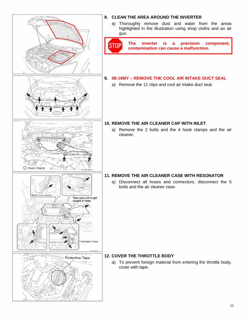
8. CLEAN THE AREA AROUND THE INVERTER
a) Thoroughly remove dust and water from the areas highlighted in the illustration using shop cloths and an air gun.
The inverter is a precision component, contamination can cause a malfunction.
9. 08-10MY ‒ REMOVE THE COOL AIR INTAKE DUCT SEAL
a) Remove the 11 clips and cool air intake duct seal.
10. REMOVE THE AIR CLEANER CAP WITH INLET
a) Remove the 2 bolts and the 4 hook clamps and the air cleaner.
11. REMOVE THE AIR CLEANER CASE WITH RESONATOR
a) Disconnect all hoses and connectors, disconnect the 5 bolts and the air cleaner case.
12. COVER THE THROTTLE BODY
a) To prevent foreign material from entering the throttle body, cover with tape.
11

13. 06-07MY ‒ REMOVE THE INVERTER BRACKET No.5
14. 06-07MY ‒ REMOVE THE POWER STEERING ECU ASSEMBLY
Wear insulating gloves when removing the power steering gear ECU, circuit voltage is approximately 42V.
a) Remove the ground wire bolt and ground wire.
b) Wrap the ground terminal with insulating tape.
c) Remove the 2 connectors as described in the illustration.
d) Wrap the terminals of the connectors with insulating tape.
e) Disconnect the 2 wire harness clamps.
f) Remove the 2 bolts and the ECU.
15. 06-07MY ‒ REMOVE THE POWER STEERING ECU BRACKET
a) Remove the bolt and bracket.
12

16. DISPLACE THE INVERTER RESERVE TANK SUB ASSEMBLY
a) Confirm the tank cap is securely tightened.
b) Plug the overflow hose, then fix the hose with tape as illustrated to prevent coolant leakage.
c) Remove the 2 bolts for the reserve tank.
d) Confirm the 2 hoses connected to the reserve tank are secure.
17. 06-07MY ‒ REMOVE THE JUNCTION BLOCK COVER
NOTE: The reserve tank cannot be displaced unless the cover is removed.
18. 08-10MY ‒ REMOVE THE No.2 UPPER RELAY BLOCK COVER
NOTE: The reserve tank cannot be displaced unless the cover is removed.
13
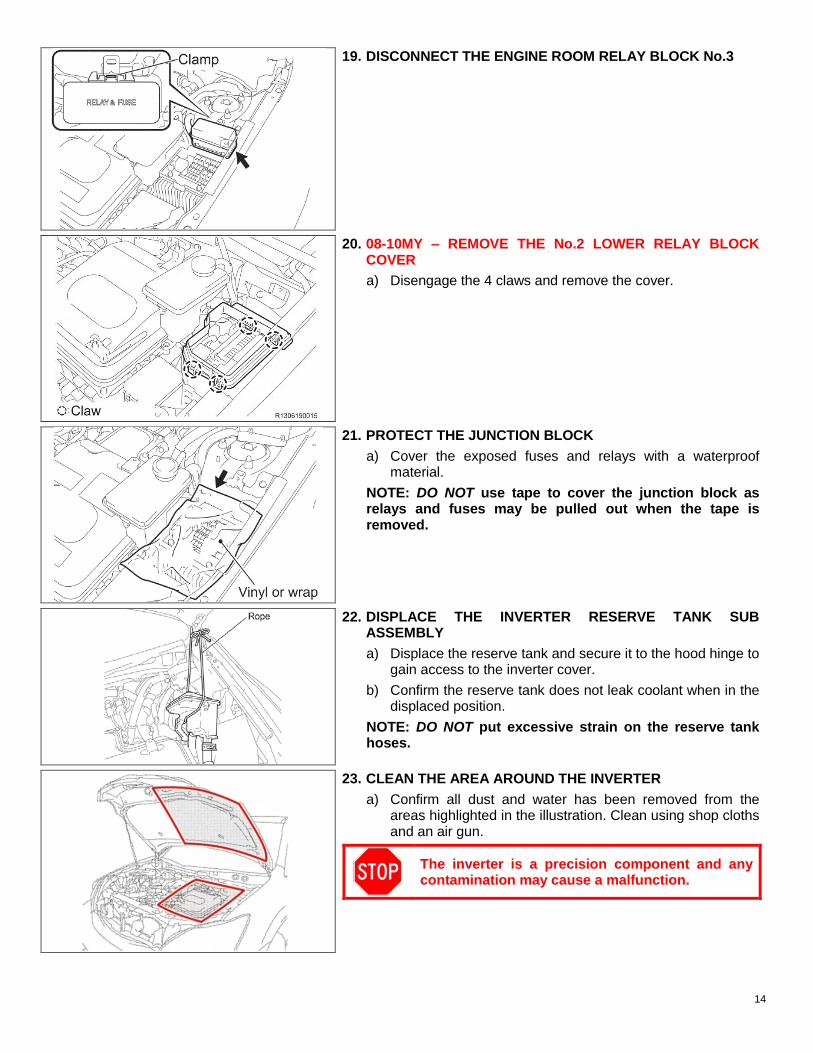
19. DISCONNECT THE ENGINE ROOM RELAY BLOCK No.3
20. 08-10MY ‒ REMOVE THE No.2 LOWER RELAY BLOCK COVER
a) Disengage the 4 claws and remove the cover.
21. PROTECT THE JUNCTION BLOCK
a) Cover the exposed fuses and relays with a waterproof material.
NOTE: DO NOT use tape to cover the junction block as relays and fuses may be pulled out when the tape is removed.
22. DISPLACE THE INVERTER RESERVE TANK SUB ASSEMBLY
a) Displace the reserve tank and secure it to the hood hinge to gain access to the inverter cover.
b) Confirm the reserve tank does not leak coolant when in the displaced position.
NOTE: DO NOT put excessive strain on the reserve tank hoses.
23. CLEAN THE AREA AROUND THE INVERTER
a) Confirm all dust and water has been removed from the areas highlighted in the illustration. Clean using shop cloths and an air gun.
The inverter is a precision component and any contamination may cause a malfunction.
14

THE FOLLOWING CONFIRMATION STEPS ARE VITAL CONFIRM THESE STEPS ARE FOLLOWED CLOSELY
PERFORM THIS INTERMEDIATE INSPECTION BEFORE BEGINNING WORK ON THE INVERTER.
1. Is the work space clear of dust and water?
2. Is the “Working with high voltage” warning sign posted?
3. Is the auxiliary battery disconnected and the service grip in a secure location (in your pocket)?
4. Is the inverter reserve tank displaced securely and free of leaks?
5. Are the areas around the inverter and the underside of the hood properly cleaned?
6. Are you wearing electrical insulating gloves that are in good condition?
7. Is the protective cover A clean and available for use?
8. Have you discharged all potential static electricity from your person?
D. INVERTER DISASSEMBLY
• It is extremely important to prevent contamination of the inverter assembly. • Confirm the work area is clean and free from airborne matter. • Be sure to wear electrical insulating gloves during the entire inverter disassembly procedure. • DO NOT use any air tools or power tools during the inverter disassembly procedure. • Confirm all tools used on HV components are insulated or wrapped with insulating tape. • Internal components in the inverter are not available as service parts, be careful when
removing, storing, and reinstalling these components.
1. REMOVE THE INVERTER COVER
a) Remove the bolt and the interlock bracket.
b) Wrap the terminal with insulating tape.
Confirm the entire cowl assembly has been removed prior to removing the inverter cover. Failure to do so could result in damage in the inverter.
c) Loosen the 12 bolts evenly in 2 increments to remove the cover.
NOTE: • DO NOT deform the cover during removal. • To prevent damage to the insulating gloves, wear work
gloves over the insulating gloves.
• Take extra precautions to prevent foreign material from entering the inverter.
• DO NOT touch the circuit board inside the inverter.
d) Store the inverter cover in a safe location to prevent damage to the inverter cover gasket.
2. PERFORM A FINAL VOLTAGE CHECK
a) Measure the voltage at the points indicated in the illustration.
Standard Voltage: 0V
NOTE: If voltage is present, confirm all previous steps to disable the high voltage system have been followed.
15

NOTE: • To prevent dropping any bolts into the inverter it may be
necessary to use a magnet to pick up bolts as they are loosened.
• If bolts are dropped into the bottom section of the inverter it may be necessary to completely remove the inverter for retrieval.
3. DISCONNECT THE MG ECU CONNECTORS
a) Remove the ground bolt.
b) Disconnect the 2 connectors and the 2 grommets.
c) 4WD − Disconnect the 3 connectors and remove the wires from the clamps. 2WD – Disconnect the 2 connectors and remove the wires from the clamps.
4. INSTALL PROTECTIVE COVER A
a) Immediately install the cover to protect the circuit board from damage and contamination.
NOTE: Use caution when installing the cover to avoid damaging the MG ECU.
16

5. PROTECT THE CONNECTORS AND HARNESS
a) Cover the disconnected connectors and terminal with insulating tape.
b) Bundle the harness and secure it away from the inverter.
NOTE: Confirm the harness is positioned so the sharp edge of the inverter case does not cut the wires.
6. REMOVE THE AIR CONDITIONER HARNESS SUB ASSEMBLY
a) Disconnect the connector.
b) Remove the 2 ground bolts.
c) Raise the tab of the fuse box to remove it from the bracket.
d) Raise the tab of the connector to remove it from the bracket.
DO NOT remove the harness until all connectors have been disconnected to prevent damaging components.
7. DISCONNECT THE ENGINE WIRE No.4
a) Cover the connector with insulating tape.
b) Remove the bolt.
c) Disconnect the grommet.
d) Disconnect the harness clamp located outside the inverter.
NOTE: DO NOT disconnect the harness clamp located inside the inverter at this time to avoid damaging the clamp or the smoothing capacitor.
8. REMOVE THE SMOOTHING CAPACITOR
a) 4WD – Remove the 11 bolts. 2WD – Remove the 9 bolts.
b) Cover the terminals with insulating tape.
NOTE: Confirm protective cover A is fully installed.
17

c) Lift the smoothing capacitor.
d) Disconnect the wire harness clamp.
e) Remove the smoothing capacitor.
NOTE: • DO NOT bend the insulation bracket. • Handle the smoothing capacitor carefully.
f) Store the smoothing capacitor with protective cover A down.
NOTE: • DO NOT store the smoothing capacitor with protective
cover A facing up. • DO NOT cover the smoothing capacitor with a shop cloth to
avoid damaging the insulation bracket. • Store the smoothing capacitor in a location that is free of
dust and other airborne matter.
9. PROTECT THE HARNESSES AND TERMINALS
a) Position the disconnected harness outside the inverter so it does not obstruct the work.
b) Cover the terminals indicated in the illustration with insulating tape.
18

c) Secure the terminal to the other harnesses at the rear of the inverter so it does not obstruct the work.
d) Secure the 2 forward terminals to the inner wall of the inverter as indicated in the illustration so they do not obstruct the work.
NOTE: DO NOT position the terminals in a way that will allow the inverter cover to pinch them when the cover is temporarily installed.
10. DISCONNECT THE HIGH VOLTAGE CABLES
a) 4WD – Remove the 15 bolts and disconnect the high voltage MG1, MG2, and MGR cables. Cover the terminals with insulating tape. 2WD – Remove the 10 bolts and disconnect the high voltage MG1 and MG2 cables. Cover the terminals with insulating tape.
To prevent contamination, DO NOT use the bolts that were removed from the outside of the inverter on the inside.
11. 2WD ONLY – INSTALL PROTECTIVE COVER B a) Position the wire harness in the groove of the inverter
case.
b) Install protective cover B using an inverter cover bolt.
NOTE: • Tighten the bolt by hand ONLY. • Protective Cover B will be installed on 4WD vehicles at
step 18.
19

12. REMOVE THE MG2 BUS BAR
a) Remove the 4 bolts and the bus bar.
13. REMOVE THE MG1 BUS BAR
a) Remove the 4 bolts and the bus bar.
14. 4WD ONLY − REMOVE THE INVERTER BRACKET
a) Remove the bolt and the bracket.
15. 4WD ONLY – REMOVE THE MGR BUS BAR
a) Remove the 5 bolts and the bus bar.
b) Cover the terminals indicated in the illustration with insulating tape.
20

16. 4WD ONLY – REMOVE THE INVERTER CURRENT SENSOR No.1
a) Disconnect the connector.
b) Remove the 2 bolts and the sensor.
17. REMOVE THE INVERTER WIRE HARNESSES
a) 4WD ONLY – Disconnect the 2 clamps and the connector and remove the harness. Attach insulating tape to the connector indicated in the illustration. 2/4WD – Disconnect the 2 clamps and the connector and remove the harness.
18. INSTALL PROTECTIVE COVER B
a) Position the wire harness in the groove of the inverter case.
b) Install protective cover B using an inverter cover bolt.
NOTE: Tighten the bolt by hand ONLY.
19. REMOVE THE HYBRID VEHICLE CAPACITOR SUB ASSEMBLY
a) Remove the 2 terminal screws.
b) Remove the 4 bolts and the capacitor.
21

20. REMOVE THE INTELLIGENT POWER MODULE (IPM) TRANSISTOR
a) Mark the IPM transistor so that it is not reused.
b) Remove the 12 bolts.
c) Lift one side of the IPM transistor to release the connection caused by the heat conductive grease.
d) Remove the IPM transistor.
DO NOT use any pry tools when removing the IPM transistor, this may damage the inverter case.
E. INVERTER CLEANING
NOTE: • DO NOT spray brake cleaner directly in the inverter. • DO NOT use an air gun in the inverter.
1. CLEAN THE INVERTER CASE
a) Use a shop cloth soaked with brake cleaner to remove the grease.
b) Wipe the grease toward the center groove in the case to avoid getting the grease in the bolt holes.
• If grease is in the bolt holes clean carefully with a shop cloth soaked in brake cleaner.
• Confirm no pieces of the shop cloth remain in the inverter.
• Confirm all electrical terminals are free from grease.
c) Confirm ALL grease is removed from the inverter case.
d) Install the 2 installation studs.
2. TEMPORARILY INSTALL THE INVERTER COVER
a) Install the inverter cover while applying grease to the new IPM transistor to prevent contamination in the inverter assembly.
NOTE: • DO NOT remove protective cover B • DO NOT pinch any harnesses between the cover and
inverter.
22

VII. GREASE APPLICATION
THE FOLLOWING CONFIRMATION STEPS ARE VITAL CONFIRM THESE STEPS ARE FOLLOWED CLOSELY
PERFORM THIS INTERMEDIATE INSPECTION BEFORE APPLYING GREASE TO THE IPM TRANSISTOR.
1. Is the smoothing capacitor stored properly with protective cover A installed?
2. Are the disconnected high voltage terminals covered with insulating tape?
3. Has the inverter case been thoroughly cleaned?
4. Is the inverter cover temporarily installed?
5. Is the grease application work space clear of dust, water and other forms of contamination?
6. Is the masking plate and squeegee clean and in good condition?
7. Have you discharged all potential static electricity from your person?
A. IPM TRANSISTOR ASSEMBLY
1. ASSEMBLE THE NEW IPM TRANSISTOR
a) Place the new IPM transistor on a clean shop cloth.
DO NOT touch the circuit board that is between the upper and lower sections of the IPM transistor.
b) Install the sub capacitor with the 4 bolts.
Torque: 6.0N∙m (61kgf∙cm, 53in. lbf)
c) Install the 2 wires with the 2 screws.
NOTE: • DO NOT attach the wires to the incorrect terminals. • Position the wires so they do not protrude past the IPM
transistor.
23

B. IPM TRANSISTOR GREASE APPLICATION
1. PLACE THE IPM TRANSISTOR UPSIDE DOWN ON A CLEAN SURFACE
2. INSPECT THE MASKING PLATE AND SQUEEGEE
a) Confirm the masking plate and squeegee are clean.
b) Confirm the masking plate and squeegee are not bent or damaged.
3. INSTALL THE MASKING PLATE
a) Place the IPM transistor so the 3 notches are at the top.
b) Align the upper left notch in the masking plate with the alignment notch in the IPM transistor.
c) Tighten the masking plate by hand using the 4 nuts/bolts provided.
NOTE: DO NOT use tools when tightening the masking plate to prevent damage.
d) Confirm the masking plate is installed in the correct position.
e) Confirm the masking plate is securely attached.
f) Confirm the masking plate is clean.
24

4. PREPARE 2 TUBES OF THERMAL CONDUCTIVE GREASE
a) Knead the tubes to confirm the grease is properly mixed. b) Clean the tubes with brake cleaner.
NOTE: The tubes may be used to apply the grease, it is critical that they are clean.
NOTE: • Two tubes of grease are necessary for each IPM transistor. • The first tube of grease will cover the upper half of the IPM transistor
and the second tube will cover the lower half as indicated in the illustration.
5. APPLY THE FIRST TUBE OF GREASE
a) Confirm the area the first tube of grease will cover.
b) Confirm the first 5mm of grease is applied on the masking plate as the initial portion of grease may not be completely mixed.
c) Apply the grease by following the target notches on the masking plate.
d) The grease should be applied in strips that are approximately 6mm wide and 2.5mm in height. (This is the size of the target notches on the masking plate)
e) Confirm grease is applied fully from start to finish in the masking plate windows.
6. APPLY THE SECOND TUBE OF GREASE
a) Confirm the area the second tube of grease will cover.
b) Confirm the first 5mm of grease is applied on the masking plate as the initial portion of grease may not be completely mixed.
c) Apply the grease by following the target notches on the masking plate.
d) The grease should be applied in strips that are approximately 6mm wide and 2.5mm in height. (This is the size of the target notches on the masking plate)
e) Confirm grease is applied fully from start to finish in the masking plate windows.
25

7. SPREAD THE GREASE
a) Position the IPM transistor so the alignment notch on the masking plate is in the upper left position.
b) Hold the squeegee at a 45 degree angle.
c) Beginning on the upper side of the IPM transistor, slide the squeegee down past the bottom of the application windows.
NOTE: To ensure all grease is used effectively, DO NOT slide the squeegee into the bolts.
d) Lift the squeegee with the grease.
e) Turn the squeegee around and slide it from the bottom of the IPM transistor up past the top of the application windows.
DO NOT remove the excess grease from the squeegee until it has been confirmed that the grease has been spread correctly.
26

THE FOLLOWING STEPS ARE VITAL CONFIRM THESE STEPS ARE FOLLOWED CLOSELY
CONFIRM THE CONDITION OF THE THERMAL CONDUCTIVE GREASE
SAMPLE CONDITION & ACTION REQUIRED
CONDITION: Smooth surface and complete coverage. ACTION: Proceed to: SECTION VIII. REASSEMBLY
CONDITION: Grease unsmooth. Metal surface of the IPM transistor NOT visible through the grease. ACTION: Proceed to: SECTION VIII. REASSEMBLY
CONDITION: Grease unsmooth. Metal surface of the IPM transistor visible through the grease. ACTION: Proceed to: STEP C #2. REAPPLY GREASE TO THE NEEDED AREAS
CONDITION: Hole or imperfection in the grease exposing the metal surface of the IPM transistor. ACTION: Proceed to: STEP C #2. REAPPLY GREASE TO THE NEEDED AREAS
CONDITION: Foreign material in the grease. ACTION: Proceed to: STEP C #1. REMOVE FOREIGN MATERIAL FROM THE GREASE
27

C. GREASE APPLICATION CORRECTION (Only perform these steps if the above inspection determines it is necessary)
1. REMOVE FOREIGN MATERIAL FROM THE GREASE
a) Use one of the tubes of grease to remove the foreign material from the grease.
NOTE: Confirm the tube is clean before use.
2. REAPPLY GREASE TO THE NEEDED AREAS
a) Collect the grease remaining on the squeegee using one of the tubes of grease.
NOTE: Confirm the tube is clean before use.
b) Apply the grease the areas with a shortage.
c) Use the squeegee as before to smooth the grease.
d) Reconfirm the condition of the grease using the confirmation steps on the previous page.
28

VIII. REASSEMBLY
A. INVERTER REASSEMBLY
TORQUE SPECIFICATIONS INSIDE THE INVERTER ARE CRITICAL CONFIRM ALL BOLTS ARE TORQUED AS OUTLINED IN THESE INSTRUCTIONS
NOTE: • To prevent dropping any bolts into the inverter it may be necessary to use a
magnet to set the bolts as they are installed. • If bolts are dropped into the bottom section of the inverter it may be
necessary to completely remove the inverter for retrieval.
1. REMOVE THE MASKING PLATE
a) Remove the 4 nuts and bolts.
b) Slowly remove the masking plate.
• DO NOT displace the grease when removing the masking plate. If the grease is scraped off when removing the plate, return to STEP B. IPM TRANSISTOR GREASE APPLICATION
2. CONFIRM THE INVERTER RESERVE TANK SUB ASSEMBLY IS NOT LEAKING
a) Before installing the IPM transistor, confirm there is no coolant leaking.
3. INSTALL THE NEW IPM TRANSISTOR
Be sure to wear electrical insulating gloves during the inverter reassembly procedure.
a) Remove the inverter cover.
• Confirm the inside of the inverter is clean. • DO NOT touch the circuit board in the IPM
transistor. • Confirm the 2 installation studs are installed.
b) Hold the front and back of the IPM transistor and place it in the inverter.
NOTE: Confirm the IPM transistor is positioned correctly before installation as it can be installed in two different positions.
29

c) Loosely install 10 bolts.
d) Remove the 2 installation studs.
e) Loosely install the 2 remaining bolts.
f) Tighten the 12 bolts in the sequence shown in the illustration.
Torque: 6N∙m (61kgf∙cm, 53 in.lbf)
NOTE: Confirm the 12 bolts are tightened in the correct sequence to ensure the grease contacts correctly.
4. 4WD ONLY −REMOVE PROTECTIVE COVER B
NOTE: Protective Cover B will be removed on STEP 11 on 2WD vehicles.
5. INSTALL THE INVERTER WIRE HARNESSES
a) 4WD ONLY – Connect the 2 clamps and 1 connectors. 2/4WD – Connect the 2 clamps and the connector.
30

6. 4WD ONLY − INSTALL THE INVERTER CURRENT SENSOR No.1
a) Install the current sensor. Confirm the sensor is installed in the locating pin.
b) Install the 2 bolts.
Torque: 8N∙m (82kgf∙cm, 71 in.lbf)
The bolts can be installed even if the locating pin is not aligned. Confirm the sensor is installed in the locating pin.
c) Connect the electrical connector.
7. 4WD ONLY – INSTALL THE MGR BUS BAR
a) Remove the insulating tape attached to the terminals and confirm they are clean.
b) Install the bus bar.
c) Install the 5 bolts in the sequence shown in the illustration.
Torque: 8N∙m (82kgf∙cm, 71in. lbf)
NOTE: DO NOT install a bolt in the sixth hole at this time, only confirm the terminal is aligned correctly.
8. 4WD ONLY − INSTALL THE INVERTER BRACKET
a) Install the bracket with 1 bolt.
Torque: 8N∙m (82kgf∙cm, 71in. lbf)
NOTE: The inverter bracket should be present on 2WD vehicles, the bracket should not have been reomved.
31

9. INSTALL THE MG1 BUS BAR
a) Confirm the terminals are clean.
b) Install the bus bar. Confirm the bus bar is installed in the locating pin.
c) Install the 4 bolts in the sequence shown in the illustration.
Torque: 8N∙m (82kgf∙cm, 71in. lbf)
The bolts can be installed even if the locating pin is not aligned. Confirm the sensor is installed in the locating pin.
10. INSTALL THE MG2 BUS BAR
a) Confirm the terminals are clean.
b) Install the bus bar. Confirm the bus bar is installed in the locating pin.
NOTE: Confirm the harnesses are routed correctly.
The bolts can be installed even if the locating pin is not aligned. Confirm the sensor is installed in the locating pin.
c) Install the 4 bolts in the sequence shown in the illustration.
Torque: 8N∙m (82kgf∙cm, 71in. lbf)
The bolts can be installed even if the locating pin is not aligned. Confirm the sensor is installed in the locating pin.
32

11. 2WD ONLY – REMOVE PROTECTIVE COVER B
NOTE: Protective Cover B was removed on STEP 4 on 4WD vehicles.
12. INSTALL THE HIGH VOLTAGE CABLES
a) Remove the insulating tape attached to the terminals and confirm they are clean.
b) 4WD – Install the 15 bolts. 2WD – Install the 10 bolts.
Torque: 10N∙m (102kgf∙cm, 84in. lbf)
NOTE: If there is difficulty installing the high voltage cables, reconfirm the bus bars are installed in their locating pins.
To prevent contamination, DO NOT use the bolts that were removed from the outside of the inverter on the inside.
13. PREPARE THE INVERTER FOR SMOOTHING CAPACITOR INSTALLATION
a) Secure the inverter harnesses so they do not interfere when installing the smoothing capacitor.
b) Move the 2 terminals that were fixed inside the inverter during the disassembly process to the outside of the inverter.
c) Remove the insulating tape attached to the terminals.
14. INSTALL THE SMOOTHING CAPACITOR
a) Hold the smoothing capacitor with protective cover A installed.
b) Carefully place the smoothing capacitor in the inverter.
• DO NOT catch any wires when installing the smoothing capacitor.
• Pay close attention to the insulating bracket, this bracket must not be bent and must be positioned between the inverter case and the IPM transistor.
c) Install the 4 bolts.
Torque: 8N∙m (82kgf∙cm, 71in. lbf)
33

d) Remove the insulating tape on the 2 wires.
e) Install the bolts.
4WD – Install the 6 bolts. 2WD – Install the 4 bolts.
Torque: 8N∙m (82kgf∙cm, 71in. lbf)
NOTE: DO NOT mistake the connection points of the terminals.
15. INSTALL THE AIR CONDITIONING HARNESS SUB ASSEMBLY
a) Install the connector.
b) Install the fuse box.
c) Confirm the harness is routed correctly.
d) Confirm the terminals are clean and install the 2 ground bolts.
Torque: 8N∙m (82kgf∙cm, 71in. lbf)
16. CONNECT THE ENGINE WIRE No.4
a) Remove the insulating tape from the terminal.
b) Connect the connector, the harness clamps, and the grommet.
c) Install the bolt.
Torque: 6N∙m (61kgf∙cm, 53in. lbf)
17. CONNECT THE MG ECU CONNECTORS
a) Remove the insulating tape from the connectors.
b) Remove protective cover A.
c) Connect the connectors following the sequence in the illustration. 4WD – 3 connectors 2WD – 2 connectors
d) Connect the 2 ground bolts.
Torque: 8N∙m (82kgf∙cm, 71in. lbf)
• Confirm that all harnesses are routed correctly and all connectors and ground bolts are secure.
• DO NOT touch the MG ECU.
34

e) Connect the 2 connectors and fit the 2 grommets.
• Cross the 2 harnesses inside the inverter. • The harnesses can be crossed in either
direction. • Confirm the grommets are clean before
installing to prevent leaks.
THE FOLLOWING CONFIRMATION STEPS ARE VITAL CONFIRM THESE STEPS ARE FOLLOWED CLOSELY
PERFORM THIS INTERMEDIATE INSPECTION BEFORE INSTALLING THE INVERTER CASE COVER. 1. Are the high voltage cables (MG1, MG2 and MGR for 4WD) connected correctly? 2. Are all of the MG ECU connectors secured and the ground bolts connected? 3. Have all components been installed correctly in the inverter assembly?
18. INSTALL THE INVERTER COVER
a) Confirm the cover gasket is set in the cover groove.
b) Confirm the cover gasket and inverter mating surface are clean.
c) Install the cover using the 12 bolts.
Torque: 10N∙m (102kgf∙cm, 84in. lbf)
NOTE: The cover gasket can be reused even if it has come out of the groove.
d) Remove the insulating tape from the interlock bracket.
e) Install the bracket with the 1 bolt.
Torque: 10N∙m (102kgf∙cm, 84in. lbf)
35

B. VEHICLE REASSEMBLY
1. CLEAN THE THROTTLE BODY
a) Use a shop cloth soaked in throttle plate cleaner to clean the throttle body.
NOTE: • DO NOT spray the throttle valve directly. • This procedure should be performed to ensure the
engine learn values are set correctly.
2. INSTALL THE COMPONENTS ILLUSTRATED BELOW
NOTE: • Install ALL air intake system components prior to
attempting READY ON; otherwise, DTCs may occur.
• Wear insulating gloves when installing the power steering ECU components on 06-07MY.
• For detailed installation information, refer to the repair manual.
3. INSTALL THE SERVICE GRIP
4. INSTALL THE NEGATIVE BATTERY CABLE
5. CONFIRM VEHICLE OPERATION
a) Turn the vehicle to READY ON.
b) Confirm the vehicle is in park.
c) Turn the air conditioner on high and allow vehicle to run for 3 minutes.
d) Confirm auxiliary battery voltage.
Specification: 13 to 15 V
e) Check for DTCs. If DTCs are output use the repair manual and the trouble shooting table in the Appendix of these instructions to diagnose.
NOTE: • If DTCs are present after IPM replacement, first confirm IPM replacement was performed correctly, if
it is determined that inverter replacement is required you MUST contact TAS (800-233-3178) to confirm your diagnosis, then contact your regional representative to obtain operation codes for dealership reimbursement.
• If DTCs that were not present prior to IPM replacement are present after IPM replacement, confirm IPM replacement was performed correctly.
36

6. INSTALL ALL REMAINING COMPONENTS
7. CHECK FOR DIAGNOSTIC TROUBLE CODES
8. TEST DRIVE THE VEHICLE
9. PERFORM SYSTEM INITIALIZATIONS
◄ VERIFY REPAIR QUALITY ► − Confirm the work area is very clean before disassembling the inverter − Confirm ALL removal steps are followed, to prevent damage DO NOT skip any steps − Confirm the inverter is cleaned thoroughly and the grease is applied correctly to the IPM transistor − Confirm ALL installation steps are followed
If you have any questions regarding this recall, please contact your regional representative
IX. APPENDIX
A. RECALL PARTS DISPOSAL
As required by Federal Regulations, please make sure all recalled parts (original parts) removed from the vehicle are disposed of in a manner in which they will not be reused, unless requested for parts recovery return.
B. TROUBLESHOOTING TABLE
Use this table if any DTCs are output after performing the campaign. If the DTC output is not listed in this table, or checking the connectors does not remedy the condition, refer to the repair manual for additional diagnostic information.
37

DTC Connector to inspect DTC Connector to inspect A B C D E F G H A B C D E F G H
B1477/71 O P0A41-245 O B1477/77 O P0A45-669 O
P0A02-719 O P0A46-671 O P0A03-720 O P0A47-670 O P0A08-264 O P0A4B-253 O P0A09-265 O P0A4C-513 O P0A10-263 O P0A4D-255 O P0A1A-151 O O O O O P0A55-687 O O P0A1A-155 O O O O O P0A60-288 O O P0A1A-156 O O O O O P0A60-289 O O P0A1A-158 O O O O O P0A60-290 O O P0A1A-166 O O O O O P0A60-292 O O P0A1A-200 O O O O O P0A60-294 O O P0A1A-658 O O O O O P0A60-501 O O P0A1A-659 O O O O O P0A63-296 O O P0A1A-791 O O O O O P0A63-297 O O P0A1A-792 O O O O O P0A63-298 O O P0A1A-793 O O O O O P0A63-300 O O P0A1B-163 O O O O O P0A63-302 O O P0A1B-164 O O O O O P0A63-502 O O P0A1B-168 O O O O O P0A69-677 O O P0A1B-192 O O O O O P0A69-679 O O P0A1B-193 O O O O O P0A69-680 O O P0A1B-195 O O O O O P0A69-683 O O P0A1B-196 O O O O O P0A69-684 O O P0A1B-198 O O O O O P0A69-688 O O P0A1B-511 O O O O O P0A6C-678 O O P0A1B-512 O O O O O P0A6C-681 O O P0A1B-661 O O O O O P0A6C-682 O O P0A1B-662 O O O O O P0A6C-685 O O P0A1B-781 O O O O O P0A6C-686 O O P0A1B-786 O O O O O P0A6C-689 O O P0A1B-788 O O O O O P0A72-326 O O P0A1B-794 O O O O O P0A72-327 O O P0A1B-795 O O O O O P0A72-328 O O P0A1B-796 O O O O O P0A72-330 O O P0A1C-706 O O O O O P0A72-333 O O P0A1C-707 O O O O O P0A72-515 O O P0A1C-708 O O O O O P0A75-334 O O P0A1C-709 O O O O O P0A75-335 O O P0A1C-710 O O O O O P0A75-336 O O P0A1C-711 O O O O O P0A75-338 O O P0A1C-713 O O O O O P0A75-341 O O P0A1C-715 O O O O O P0A75-516 O O P0A1C-797 O O O O O P0A78-278 O O P0A1C-798 O O O O O P0A78-280 O O P0A1C-799 O O O O O P0A78-283 O O P0A3F-243 O P0A78-285 O O P0A40-500 O P0A79-690 O O
38

DTC Connector to inspect A B C D E F G H
P0A79-691 O O P0A7A-321 O O P0A7A-323 O O P0A94-545 O P0A94-546 O P0A94-551 O P0A94-552 O P0A94-587 O P0AA6-526 P0AA6-613 P0AA6-614 P0AA6-655 P0AEF-275 O P0AF0-274 O P0AF4-673 O P0AF4-674 O P3222-313 O P3223-312 O P3227-583 O P3228-584 O U0110-159 O O O O O U0110-160 O O O O O U0110-656 O O O O O U0110-657 O O O O O Auxiliary battery
voltage error O
39

This document is intended as a technician aid. Carefully follow the complete D0M instructions found on TIS when performing this repair.
SAFETY RECALL D0M Intelligent Power Module Transistor Replacement
GREASE APPLICATION PROCEDURE OUTLINE − Confirm the grease application surface on the NEW IPM transistor is clean before applying grease − Confirm all original grease inside the inverter case has been completely removed − If the correct amount of grease is not applied the the new IPM, inverter failure may occur − Knead the tubes of grease before application to confirm the grease is properly mixed
1 Confirm the masking plate is in good condition, clean, installed in the correct position, and secured.
2 Two tubes of grease are necessary for each IPM transistor. Apply the first tube to the upper half of the IPM and the second tube to the lower half.
3Clean all original grease from the inverter using a rag soaked in brake cleaner.
4Begin on the upper side of the IPM and slide the squeegee down to spread the grease.
5 Slide the squeegee from the bottom of the IPM to the top to completely spread the grease.
After applying the grease you must confirm the grease coverage is sufficient. Use the sample images below to determine the condition of the grease.
CONDITION: Grease is smooth and coverage is complete. Proceed with reassembly.
CONDITION: Grease is not smooth and metal surface of IPM is not visible through grease. Proceed with reassembly.
CONDITION: Metal Surface of IPM is visible through grease. Additional grease must be applied.
INVERTER DISASSEMBLY PROCEDURE OUTLINE – These instructions provide an overview of the disassembly, order for reassembly is reverse − Torque specifications are critical, confirm all bolts are torqued correctly − Confirm the IPM transistor is torqued following the correct sequence − Confirm all safety precautions are followed when working on high voltage components
1
2
3
INVERTER COVER MG ECU CONNECTORS PROTECTIVE COVER A
4
5
6
AIR CONDITIONER HARNESS SMOOTHING CAPACITOR HIGH VOLTAGE CABLES
7
8
9 4WD ONLY
MG2 BUS BAR MG1 BUS BAR INVERTER BRACKET
10 4WD ONLY
114WD
ONLY
12
MGR BUS BAR INVERTER CURRENT SENSOR WIRE HARNESSES
13
14
15
PROTECTIVE COVER B SUB CAPACITOR IPM TRANSISTOR

October 1, 2013
Subject: Safety Recall DLF – Remedy Available Certain 2006 through 2008 Model Year RX 400h Vehicles Intelligent Power Module (IPM) Replacement Dear Dealer Principal: As previously announced on September 4, 2013, Lexus filed a Defect Information Report (DIR) with the National Highway Traffic Safety Administration (NHTSA) informing the agency of our intent to conduct a voluntary Safety Recall on certain 2006 through 2008 model year RX 400h vehicles. Lexus has completed remedy preparations and will now begin mailing the remedy owner letter.
Background Inside the Hybrid Inverter Assembly is an Intelligent Power Module (IPM) which contains a control board equipped with transistors. Due to variations in operating characteristics of some IPM transistors, the temperature of the transistor(s) can exceed the allowable temperature of the solder underneath the transistor. If this occurs, the solder could degrade and eventually cause heat damage to the transistor(s), illuminating various warning lights on the instrument panel. In most cases, the vehicle will enter a “fail-safe” mode, resulting in reduced power under which the vehicle can still be driven for short distances. In limited cases, the fuse of the power supply circuit could blow, causing the hybrid system to shut down. If the Hybrid System shuts down, the vehicle could stop while being driven increasing the risk of crash. The following information is provided to inform you and your staff of the remedy phase of this Safety Recall and your degree of involvement.
Remedy Lexus dealers will replace the Intelligent Power Module (IPM) at NO CHARGE to the vehicle owner. For additional information on the repair procedures, please refer to TIS. Owner Notification Lexus will begin mailing Safety Recall Notices by first class mail in phases beginning in mid-October, 2013. The owner letters will be spread over several weeks consistent with parts availability and service capacity. A sample owner letter is attached. Lexus tries very hard to obtain current customer name and address information when mailing owner letters. In the event your dealership receives a notice for a vehicle that was sold prior to the Safety Recall announcement, it is the dealership’s responsibility to forward the owner letter to the customer who purchased the vehicle. Pre-Owned Vehicles in Dealer Inventory Lexus requests dealers to conduct the remedy on any pre-owned vehicles currently in dealer inventory that are covered by this Safety Recall prior to delivery to the customer.

2
Also, as a reminder, Lexus CPO policy prohibits the certification of any vehicle with an outstanding Special Service Campaign or Safety Recall, such as this Safety Recall DLF Thus, no affected units may be sold or delivered as a CPO vehicle until the Safety Recall has been completed on that vehicle. Number and Identification of Covered Vehicles There are approximately 53,500 RX 400h (certain 2006 through 2008 model year) vehicles covered by this Safety Recall in the United States.
Model WMI Model Year VDS Start Finish
RX 400h JTJ
2006
GW31U 0001007 0004967 HW31U 0001106 0049412 GW31U 2000108 2000971 HW31U 2000103 2007397
2007 GW31U 2000995 2005870 HW31U 2007400 2039945
2008 GW31U 2005871 2851829 HW31U 2027573 2867597
Please note that only owners of the covered vehicles will be notified. If your dealership is contacted by an owner who has not yet received the notification, please verify coverage by confirming through Dealer Daily/TIS. Dealers should perform the procedure as outlined in the Technical Instructions located on TIS. Remedy Procedures Refer to TIS for the appropriate Technical Instructions (TI). Technical instructions will be posted on TIS on October 2, 2013. Conduct all applicable, non-completed Safety Recall and service campaigns on the vehicle during the time of the appointment. Repair Quality Confirmation The repair quality of covered vehicles is extremely important to Lexus. To help ensure that all vehicles have the repair performed correctly, please designate at least one associate (someone other than the individual who performed the repair) to verify the repair quality of every vehicle prior to customer delivery. Parts Ordering To assure sufficient availability of parts for scheduled appointments the Intelligent Power Module Transistor and grease have been placed on the Dealer Order Solution process. Please refer to the information sent by the facing PDC to each dealer’s parts manager for specific information on daily order limits.
Part Number Part Description Quantity Per Vehicle Remedied 04001-29148 Intelligent Power Module Transistor 1
08887-02409 Grease G747 2 NOTE: Grease G747 is considered a hazardous material and must be handled appropriately during order processing and shipping. As a result, additional time beyond that normally experienced for dealer parts orders receipt may be incurred. Please plan accordingly when communicating with the service department and when scheduling appointments for your customers.
IMPORTANT PARTS ORDERING UPDATE All Safety Recall, Service Campaign (SSC/LSC) and Customer Support Program (CSP) parts are eligible for the Monthly Parts Return Program. Please refer to Service and Parts Operations Communication 2011-20 for campaign parts that are currently returnable under
the Monthly Parts Return Program and additional details.

3
Technician Training Requirements The repair quality of covered vehicles is extremely important to Lexus. All dealership associates involved in the recall process are required to successfully complete E-Learning course LSC13A. To ensure that all vehicles have the repair performed correctly; technicians performing this recall repair are required to have the following minimum certification:
• Lexus Certified Senior or Master Diagnostic Specialists • Lexus Certified Senior or Master Service Technicians
and successful completion of Course L071 Lexus Hybrid Systems. It is the dealership’s responsibility to select technicians with the above certification level or greater to perform this Safety Recall repair. Carefully review your resources, the technician skill level, and ability before assigning technicians to this repair. It is important to consider technician days off and vacation schedules to ensure there are properly trained technicians available to perform this repair at all times Tools, Supplies and Equipment In a separate shipment scheduled to arrive October 2, 2013, your dealership was sent a package containing special service tools (SSTs) for this Safety Recall. When received, the package will have a fluorescent (green, orange, yellow or pink) label like the sample shown below for easy identification.
Part Name Sample Qty Part Name Sample Qty
Protective Cover A
1
Protective Cover B
1
Masking Plate
1
Squeegee
1
Stud Bolt
2 Masking Plate
Nut/Bolt 4
NOTE: If additional gloves are needed they can be ordered through SPX by calling 800-933-8335 (Gloves are not included in the Campaign Tool Kit)
Part Number Part Name Quantity
00002-03100-S Electrical Insulating Gloves (Small) 1 00002-03200-M Electrical Insulating Gloves (Medium)
00002-03300-L Electrical Insulating Gloves (Large)
ATTN: SERVICE MANAGER
SAFETY RECALL – DLF CAMPAIGN TOOLS

4
Warranty Reimbursement Procedures
Certain 2006 and 2008 Model Year RX 400h Vehicles Verify Vehicle Eligibility1. Check the VIN range.
2. Check the TIS Vehicle Inquiry System.
No further action required.Not Involved
Involved
Campaign complete.Return the vehicle to the customer.
Replace the Intelligent Power Module (IPM) Transistor.
Confirm and record any DTCs that may be present.
Confirm any DTCs that may be present. Use the repair manual and
the troubleshooting table in the Appendix section of the technical
instructions to diagnose.
Safety Recall
Opcode Description Flat Rate Hour
DLF 3530HA Replace IPM for 2WD model GW31U 3.9 hr/vehicle 3530HD Replace IPM for AWD model HW31U 4.0 hr/vehicle
• The flat rate times include 0.1 hours for administrative cost per unit for the dealership. • Toyota Genuine Brake Cleaner and Toyota Genuine Throttle Plate Cleaner or equivalent can be claimed as sublet type
“OF” under opcode 3530HA and 3530HD at a rate of $5.00 per vehicle (marking pens and electrical tape is also included in the sublet cost)
• Parts replaced under opcode 3530HA and 3530HD are subject to warranty parts return, any misuse of these operation codes will result in a warranty claim debit
Safety Recall Opcode Description Flat Rate Hour
DLF Contact Area Rep.
Replace the IPM, DTC present after IPM replacement, replace Inverter Assembly on AWD Models HW31U
Contact Area Rep.
Replace the IPM, DTC present after IPM replacement, replace Inverter Assembly on 2WD Models GW31U
Contact Area Rep.
• Area representative will provide available sublets for this operation Important Note: If you have DTCs present after performing the IPM replacement, please consult the Technical Instruction Appendix and repair manual for DTC diagnosis. In the event you need further assistance diagnosing the current DTCs please contact the Technical Assistance Hotline – QA Powertrain Department at 800-233-3178. Do not file a claim for Intelligent Power Module replacement; you will need to obtain an opcode from your Area representative for Inverter Replacement.
Lexus’ usual customer care amenities of car wash and fuel tank fill apply to this Safety Recall. Additionally, one day of rental vehicle expense (to a maximum of $45/day) or the cost of pick up and delivery of the customer’s vehicle may be claimed if required and subject to the guidelines published in the Safety Recall/Special Service Campaign/Limited Service Campaign General Procedures document on TIS.
Media Contacts It is imperative that all media contacts (local and national) receive a consistent message. In this regard, all media contacts must be directed to Cindy Knight (310) 468-2170 in Toyota Corporate Communications. (Please do not provide this number to customers. Please provide this contact to only media associates.)

5
Customer Contacts A Q&A is attached to assist you in responding to any customer questions or concerns. If the customer has any further questions they are requested to contact the Lexus Customer Assistance Center at 1-800-255-3987 Monday through Friday, 5:00 am to 6:00 pm PST, or Saturday, 7:00 am through 4:00 pm PST. Please review this notification with your entire service and parts staff to familiarize them with the proper step-by-step procedures required to implement this Safety Recall. Thank you for your understanding and cooperation.
Lexus, a Division of Toyota Motor Sales, USA, Inc. Attachments Cc: Customer Satisfaction Manager
General Manager Parts Manager Pre-owned Manager Service Manager Warranty Administrator

Page 1 of 3 © 2013 Lexus Motor Sales, USA
Safety Recall DLF- Remedy Available Certain 2006 through 2008Model Year RX 400h Vehicles Intelligent Power Module (IPM) Replacement Background As previously announced on September 4, 2013, Lexus filed a Defect Information Report (DIR) with the National Highway Traffic Safety Administration (NHTSA) informing the agency of our intent to conduct a voluntary Safety Recall on certain 2006 through 2008 model year RX 400h vehicles. Lexus has completed remedy preparations and will now begin mailing the remedy owner letter. Q1: What is the condition? A1: Inside the Hybrid Inverter Assembly is an Intelligent Power Module (IPM) which contains a control board equipped with transistors.
Due to variations in operating characteristics of some IPM transistors, the temperature of the transistor(s) can exceed the allowable temperature of the solder underneath the transistor. If this occurs, the solder could degrade and eventually cause heat damage to the transistor(s), illuminating various warning lights on the instrument panel. In most cases, the vehicle will enter a “fail-safe” mode, resulting in reduced power under which the vehicle can still be driven for short distances. In limited cases, the fuse of the power supply circuit could blow, causing the hybrid system to shut down. If the Hybrid System shuts down, the vehicle could stop while being driven increasing the risk of crash.
Q1a: What is the Hybrid System Inverter? A1a: The hybrid system inverter converts high-voltage DC, stored in the HV battery, into AC for the motor generator. It also
converts AC into DC during regenerative braking for storage in the HV battery. Q2: Which Warning Lamps are illuminated on the instrument panel when the vehicle enters fail-safe driving mode? A2: All of the following warning lights and messages will be illuminated on the instrument panel when the vehicle enters the fail-safe driving
mode. The fail-safe driving mode will result in reduced motive power in which the vehicle can still be driven for short distances. Warning lights Warning messages
Master Warning Light
Malfunction of VSC function is detected.
Slip Indicator
Hybrid system malfunction is detected.
Check Engine Warning Light
All Wheel Drive system malfunction is detected.
(yellow indicator)
Electronically Controlled Brake System Warning Light
Q2a: How long and what distance can a vehicle be driven when the vehicle enters fail-safe driving mode? A2a: The distance a vehicle will continue to travel in fail-safe driving mode will vary based upon the hybrid battery state of charge
and the road conditions. If a vehicle enters fail-safe driving mode, the driver should pull-over and stop the car in a safe area. The driver should immediately contact his/her local Lexus dealer for assistance.
Q3: What is Lexus going to do? A3: In mid-October, 2013 Lexus will send an owner notification by first class mail to owners of vehicles covered by this Safety Recall. Any authorized Lexus dealer will replace the Intelligent Power Module at No Charge to you.
Q3a: How does Lexus obtain my mailing information? A3a: Lexus uses an industry provider who works with each state’s Department of Motor Vehicles (DMV) to receive registration
or title information, based upon the DMV records. Please make sure your registration or title information is correct.

Page 2 of 3 © 2013 Lexus Motor Sales, USA
Q3b: Do I need my owner letter to have the remedy performed? A3b: You do not need an owner letter to have this recall completed; however, to assist the dealer in confirming vehicle eligibility,
we request that you present this notice at the time of your service appointment. Q4: What steps can I take to reduce the possibility of this condition from occurring prior to the availability of the remedy? A4: You may take the following steps to reduce the possibility of this condition from occurring until the remedy is completed.
Inverter Coolant Reservoir
(1) Regularly confirm that the coolant level in the inverter coolant reservoir is between FULL and LOW. If the coolant level is below the LOW line, please add coolant up to the FULL line.
Lexus dealers will inspect the coolant level, and if necessary, add coolant, at no charge at the customer’s request.
Power Meter
(2) Avoid placing a high load on the Hybrid System. Drivers may do so by refraining from towing with the vehicle until the remedy is completed.
(3) Monitor your Power Meter. The Power Meter indicates the immediate output from the Hybrid System in approximate kilowatts. Keep power usage below 100kW as much as possible. Situations where the Power Meter shows output slightly over 100kW for a brief moment should not raise any concerns.
Q4a: Will this condition occur if the Power Meter shows usage above 100kW? A4a: Situations where the Power Meter shows output slightly over 100kW for a brief moment should not raise any concerns.
Drivers should refrain from driving conditions where power output exceeds 100kW continuously and/or substantially. Drivers may do so by refraining from towing with the vehicle until the remedy is completed.
Q5: Which and how many vehicles are covered? A5: There are approximately 53,500 Lexus RX 400h vehicles and approximately 79,600 Toyota Highlander Hybrid vehicles covered
by this Safety Recall in the U.S.
Model Name Model Year Production Period Number of Vehicles
Lexus RX 400h Certain 2006 through 2008 Late February 2005
through early December 2008
Approximately 53,500 units
Toyota Highlander Hybrid Certain 2006 through 2010
Mid February 2005 through late July 2010
Approximately 79,600 units
Q5a: Are there any other Lexus or Lexus models covered by this Safety Recall? A5a: No. There are no other Lexus or Toyota models covered by this Safety Recall.

Page 3 of 3 © 2013 Lexus Motor Sales, USA
Q6: What if my vehicle was covered by the previous Safety Recall (BLD) for 2006 and 2007 Model Year RX 400h Vehicles Hybrid
System Inverter, Intelligent Power Module? A6: If you have still not had Safety Recall BLD performed, please contact any authorized Lexus dealer to schedule an appointment to
have the remedy performed as soon as possible. Q7: What if I previously paid for repairs to my vehicle for this condition? A7: Reimbursement consideration instruction will be provided in the remedy owner letter. Q8 What if I have additional questions or concerns? A8: If you have additional questions or concerns, please contact the Lexus Customer Assistance Center at 1-800-255-3987 Monday
through Friday, 5:00 am to 6:00 pm, or Saturday 7:00 am through 4:00 pm Pacific Time.

Certain 2006 through 2008 Model Year RX 400h Vehicles Hybrid System Inverter, Intelligent Power Module
IMPORTANT SAFETY RECALL NOTICE This notice applies to your vehicle: [VIN]
Dear Lexus Customer:
This notice is being sent to you in accordance with the requirements of the National Traffic and Motor Vehicle Safety Act. Lexus has decided that a defect, which relates to motor vehicle safety, exists in certain 2006 through 2008 Model Year RX 400h Vehicles.
You received this notice because our records, which are based primarily on state registration and title data, indicate that you are the current owner.
What is the condition?
Inside the hybrid inverter assembly is an Intelligent Power Module (IPM) which contains a control board equipped with transistors. Under some conditions, one or more transistors could be damaged, illuminating various warning lights on the instrument panel. In most cases, the vehicle will enter a “fail-safe” mode, resulting in reduced power under which the vehicle can still be driven for short distances. However, it is possible the fuse of the power supply circuit could blow, causing the hybrid system to shut down and resulting in the vehicle stopping while being driven. This can increase the risk of a crash.
What is Lexus going to do?
Any authorized Lexus dealer will replace the IPM at NO CHARGE to you.
What should you do?
This is an important Safety Recall
Please contact any authorized Lexus dealer and make an appointment to have the IPM replaced. Replacement of the IPM will take approximately 4 hours. However, depending upon the dealer’s work schedule, it may be necessary to make your vehicle available for a longer period of time.
You do not need an owner letter to have this recall completed; however, to assist the dealer in confirming vehicle eligibility, we request that you present this notice at the time of your service appointment.
If you would like to update your vehicle ownership or contact information, please go to www.lexus.com/ownersupdate. You will need your full 17-digit Vehicle Identification Number (VIN) to input the new information.
What if you have other questions?
Your local Lexus dealer will be more than happy to answer any of your questions and set up an appointment to perform the repair. You can find additional information and locate a Lexus dealer in your area by going online and visiting www.lexus.com. If you require further assistance, you may contact the Lexus Customer Assistance Center at 1-800-255-3987, Monday through Friday, 5:00 am to 6:00 pm, Saturday 7:00 am through 4:00 pm Pacific Time.
If you believe that the dealer or Lexus has failed or is unable to remedy the defect within a reasonable time, you may submit a complaint to the Administrator, National Highway Traffic Safety Administration, 1200 New Jersey Avenue S.E., Washington, D.C. 20590, or call the toll free Vehicle Safety Hot Line at 1-888-327-4236 (TTY: 1-800-424-9153), or go to http://www.safercar.gov.
URGENT SAFETY RECALL This is an important Safety Recall. The remedy will be
performed at NO CHARGE to you.

What if you have previously paid for repairs to your vehicle for this specific condition?
If you have previously paid for repair to your vehicle for this specific condition prior to receiving this letter, please mail a copy of your repair order and proof-of-payment to the following address for reimbursement consideration:
Lexus, a Division of Toyota Motor Sales, U.S.A., Inc Lexus Customer Assistance Center L201
19001 South Western Avenue Torrance, CA 90509
Include your name, address, and telephone number(s) in your request. Please allow us 6-8 weeks to process your request.
Please note the dealership will need to complete the Safety Recall remedy before reimbursement consideration requests can be processed.
If you are a vehicle lessor, Federal law requires that any vehicle lessor receiving this recall notice must forward a copy of this notice to the lessee within ten days.
We have sent this notice in the interest of your continued satisfaction with our products, and we sincerely regret any inconvenience this condition may have caused you.
Thank you for driving a Lexus.
Sincerely,
LEXUS, A DIVISION OF TOYOTA MOTOR SALES, U.S.A., INC.

October 1, 2013
Subject: Safety Recall DLF – Remedy Available Certain 2006 through 2008 Model Year RX 400h Vehicles Intelligent Power Module (IPM) Replacement Dear Dealer Principal: As previously announced on September 4, 2013, Lexus filed a Defect Information Report (DIR) with the National Highway Traffic Safety Administration (NHTSA) informing the agency of our intent to conduct a voluntary Safety Recall on certain 2006 through 2008 model year RX 400h vehicles. Lexus has completed remedy preparations and will now begin mailing the remedy owner letter.
Background Inside the Hybrid Inverter Assembly is an Intelligent Power Module (IPM) which contains a control board equipped with transistors. Due to variations in operating characteristics of some IPM transistors, the temperature of the transistor(s) can exceed the allowable temperature of the solder underneath the transistor. If this occurs, the solder could degrade and eventually cause heat damage to the transistor(s), illuminating various warning lights on the instrument panel. In most cases, the vehicle will enter a “fail-safe” mode, resulting in reduced power under which the vehicle can still be driven for short distances. In limited cases, the fuse of the power supply circuit could blow, causing the hybrid system to shut down. If the Hybrid System shuts down, the vehicle could stop while being driven increasing the risk of crash. The following information is provided to inform you and your staff of the remedy phase of this Safety Recall and your degree of involvement.
Remedy Lexus dealers will replace the Intelligent Power Module (IPM) at NO CHARGE to the vehicle owner. For additional information on the repair procedures, please refer to TIS. Owner Notification Lexus will begin mailing Safety Recall Notices by first class mail in phases beginning in mid-October, 2013. The owner letters will be spread over several weeks consistent with parts availability and service capacity. A sample owner letter is attached. Lexus tries very hard to obtain current customer name and address information when mailing owner letters. In the event your dealership receives a notice for a vehicle that was sold prior to the Safety Recall announcement, it is the dealership’s responsibility to forward the owner letter to the customer who purchased the vehicle. Pre-Owned Vehicles in Dealer Inventory Lexus requests dealers to conduct the remedy on any pre-owned vehicles currently in dealer inventory that are covered by this Safety Recall prior to delivery to the customer.

2
Also, as a reminder, Lexus CPO policy prohibits the certification of any vehicle with an outstanding Special Service Campaign or Safety Recall, such as this Safety Recall DLF Thus, no affected units may be sold or delivered as a CPO vehicle until the Safety Recall has been completed on that vehicle. Number and Identification of Covered Vehicles There are approximately 53,500 RX 400h (certain 2006 through 2008 model year) vehicles covered by this Safety Recall in the United States.
Model WMI Model Year VDS Start Finish
RX 400h JTJ
2006
GW31U 0001007 0004967 HW31U 0001106 0049412 GW31U 2000108 2000971 HW31U 2000103 2007397
2007 GW31U 2000995 2005870 HW31U 2007400 2039945
2008 GW31U 2005871 2851829 HW31U 2027573 2867597
Please note that only owners of the covered vehicles will be notified. If your dealership is contacted by an owner who has not yet received the notification, please verify coverage by confirming through Dealer Daily/TIS. Dealers should perform the procedure as outlined in the Technical Instructions located on TIS. Remedy Procedures Refer to TIS for the appropriate Technical Instructions (TI). Technical instructions will be posted on TIS on October 2, 2013. Conduct all applicable, non-completed Safety Recall and service campaigns on the vehicle during the time of the appointment. Repair Quality Confirmation The repair quality of covered vehicles is extremely important to Lexus. To help ensure that all vehicles have the repair performed correctly, please designate at least one associate (someone other than the individual who performed the repair) to verify the repair quality of every vehicle prior to customer delivery. Parts Ordering To assure sufficient availability of parts for scheduled appointments the Intelligent Power Module Transistor and grease have been placed on the Dealer Order Solution process. Please refer to the information sent by the facing PDC to each dealer’s parts manager for specific information on daily order limits.
Part Number Part Description Quantity Per Vehicle Remedied 04001-29148 Intelligent Power Module Transistor 1
08887-02409 Grease G747 2 NOTE: Grease G747 is considered a hazardous material and must be handled appropriately during order processing and shipping. As a result, additional time beyond that normally experienced for dealer parts orders receipt may be incurred. Please plan accordingly when communicating with the service department and when scheduling appointments for your customers.
IMPORTANT PARTS ORDERING UPDATE All Safety Recall, Service Campaign (SSC/LSC) and Customer Support Program (CSP) parts are eligible for the Monthly Parts Return Program. Please refer to Service and Parts Operations Communication 2011-20 for campaign parts that are currently returnable under
the Monthly Parts Return Program and additional details.
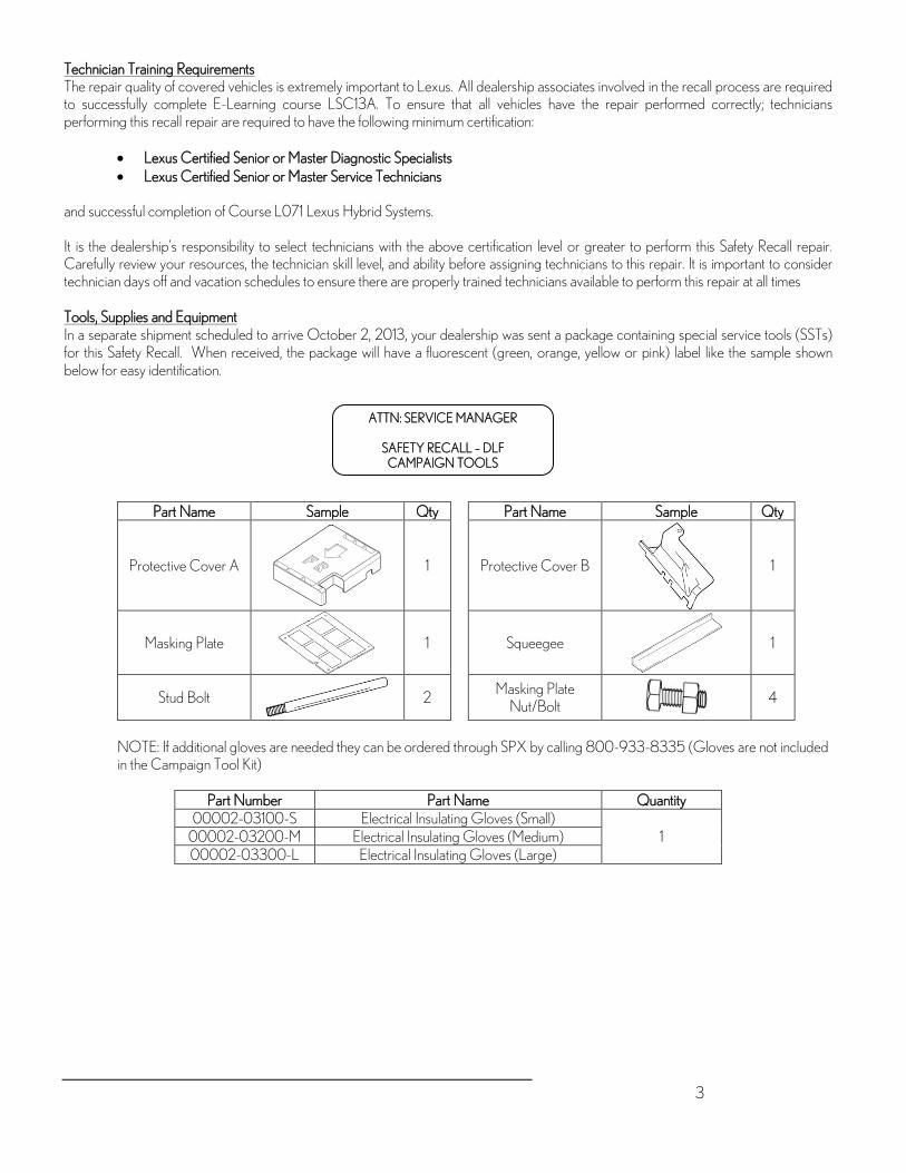
3
Technician Training Requirements The repair quality of covered vehicles is extremely important to Lexus. All dealership associates involved in the recall process are required to successfully complete E-Learning course LSC13A. To ensure that all vehicles have the repair performed correctly; technicians performing this recall repair are required to have the following minimum certification:
• Lexus Certified Senior or Master Diagnostic Specialists • Lexus Certified Senior or Master Service Technicians
and successful completion of Course L071 Lexus Hybrid Systems. It is the dealership’s responsibility to select technicians with the above certification level or greater to perform this Safety Recall repair. Carefully review your resources, the technician skill level, and ability before assigning technicians to this repair. It is important to consider technician days off and vacation schedules to ensure there are properly trained technicians available to perform this repair at all times Tools, Supplies and Equipment In a separate shipment scheduled to arrive October 2, 2013, your dealership was sent a package containing special service tools (SSTs) for this Safety Recall. When received, the package will have a fluorescent (green, orange, yellow or pink) label like the sample shown below for easy identification.
Part Name Sample Qty Part Name Sample Qty
Protective Cover A
1
Protective Cover B
1
Masking Plate
1
Squeegee
1
Stud Bolt
2 Masking Plate
Nut/Bolt 4
NOTE: If additional gloves are needed they can be ordered through SPX by calling 800-933-8335 (Gloves are not included in the Campaign Tool Kit)
Part Number Part Name Quantity
00002-03100-S Electrical Insulating Gloves (Small) 1 00002-03200-M Electrical Insulating Gloves (Medium)
00002-03300-L Electrical Insulating Gloves (Large)
ATTN: SERVICE MANAGER
SAFETY RECALL – DLF CAMPAIGN TOOLS

4
Warranty Reimbursement Procedures
Certain 2006 and 2008 Model Year RX 400h Vehicles Verify Vehicle Eligibility1. Check the VIN range.
2. Check the TIS Vehicle Inquiry System.
No further action required.Not Involved
Involved
Campaign complete.Return the vehicle to the customer.
Replace the Intelligent Power Module (IPM) Transistor.
Confirm and record any DTCs that may be present.
Confirm any DTCs that may be present. Use the repair manual and
the troubleshooting table in the Appendix section of the technical
instructions to diagnose.
Safety Recall
Opcode Description Flat Rate Hour
DLF 3530HA Replace IPM for 2WD model GW31U 3.9 hr/vehicle 3530HD Replace IPM for AWD model HW31U 4.0 hr/vehicle
• The flat rate times include 0.1 hours for administrative cost per unit for the dealership. • Toyota Genuine Brake Cleaner and Toyota Genuine Throttle Plate Cleaner or equivalent can be claimed as sublet type
“OF” under opcode 3530HA and 3530HD at a rate of $5.00 per vehicle (marking pens and electrical tape is also included in the sublet cost)
• Parts replaced under opcode 3530HA and 3530HD are subject to warranty parts return, any misuse of these operation codes will result in a warranty claim debit
Safety Recall Opcode Description Flat Rate Hour
DLF Contact Area Rep.
Replace the IPM, DTC present after IPM replacement, replace Inverter Assembly on AWD Models HW31U
Contact Area Rep.
Replace the IPM, DTC present after IPM replacement, replace Inverter Assembly on 2WD Models GW31U
Contact Area Rep.
• Area representative will provide available sublets for this operation Important Note: If you have DTCs present after performing the IPM replacement, please consult the Technical Instruction Appendix and repair manual for DTC diagnosis. In the event you need further assistance diagnosing the current DTCs please contact the Technical Assistance Hotline – QA Powertrain Department at 800-233-3178. Do not file a claim for Intelligent Power Module replacement; you will need to obtain an opcode from your Area representative for Inverter Replacement.
Lexus’ usual customer care amenities of car wash and fuel tank fill apply to this Safety Recall. Additionally, one day of rental vehicle expense (to a maximum of $45/day) or the cost of pick up and delivery of the customer’s vehicle may be claimed if required and subject to the guidelines published in the Safety Recall/Special Service Campaign/Limited Service Campaign General Procedures document on TIS.
Media Contacts It is imperative that all media contacts (local and national) receive a consistent message. In this regard, all media contacts must be directed to Cindy Knight (310) 468-2170 in Toyota Corporate Communications. (Please do not provide this number to customers. Please provide this contact to only media associates.)

5
Customer Contacts A Q&A is attached to assist you in responding to any customer questions or concerns. If the customer has any further questions they are requested to contact the Lexus Customer Assistance Center at 1-800-255-3987 Monday through Friday, 5:00 am to 6:00 pm PST, or Saturday, 7:00 am through 4:00 pm PST. Please review this notification with your entire service and parts staff to familiarize them with the proper step-by-step procedures required to implement this Safety Recall. Thank you for your understanding and cooperation.
Lexus, a Division of Toyota Motor Sales, USA, Inc. Attachments Cc: Customer Satisfaction Manager
General Manager Parts Manager Pre-owned Manager Service Manager Warranty Administrator

Page 1 of 3 © 2013 Lexus Motor Sales, USA
Safety Recall DLF- Remedy Available Certain 2006 through 2008Model Year RX 400h Vehicles Intelligent Power Module (IPM) Replacement Background As previously announced on September 4, 2013, Lexus filed a Defect Information Report (DIR) with the National Highway Traffic Safety Administration (NHTSA) informing the agency of our intent to conduct a voluntary Safety Recall on certain 2006 through 2008 model year RX 400h vehicles. Lexus has completed remedy preparations and will now begin mailing the remedy owner letter. Q1: What is the condition? A1: Inside the Hybrid Inverter Assembly is an Intelligent Power Module (IPM) which contains a control board equipped with transistors.
Due to variations in operating characteristics of some IPM transistors, the temperature of the transistor(s) can exceed the allowable temperature of the solder underneath the transistor. If this occurs, the solder could degrade and eventually cause heat damage to the transistor(s), illuminating various warning lights on the instrument panel. In most cases, the vehicle will enter a “fail-safe” mode, resulting in reduced power under which the vehicle can still be driven for short distances. In limited cases, the fuse of the power supply circuit could blow, causing the hybrid system to shut down. If the Hybrid System shuts down, the vehicle could stop while being driven increasing the risk of crash.
Q1a: What is the Hybrid System Inverter? A1a: The hybrid system inverter converts high-voltage DC, stored in the HV battery, into AC for the motor generator. It also
converts AC into DC during regenerative braking for storage in the HV battery. Q2: Which Warning Lamps are illuminated on the instrument panel when the vehicle enters fail-safe driving mode? A2: All of the following warning lights and messages will be illuminated on the instrument panel when the vehicle enters the fail-safe driving
mode. The fail-safe driving mode will result in reduced motive power in which the vehicle can still be driven for short distances. Warning lights Warning messages
Master Warning Light
Malfunction of VSC function is detected.
Slip Indicator
Hybrid system malfunction is detected.
Check Engine Warning Light
All Wheel Drive system malfunction is detected.
(yellow indicator)
Electronically Controlled Brake System Warning Light
Q2a: How long and what distance can a vehicle be driven when the vehicle enters fail-safe driving mode? A2a: The distance a vehicle will continue to travel in fail-safe driving mode will vary based upon the hybrid battery state of charge
and the road conditions. If a vehicle enters fail-safe driving mode, the driver should pull-over and stop the car in a safe area. The driver should immediately contact his/her local Lexus dealer for assistance.
Q3: What is Lexus going to do? A3: In mid-October, 2013 Lexus will send an owner notification by first class mail to owners of vehicles covered by this Safety Recall. Any authorized Lexus dealer will replace the Intelligent Power Module at No Charge to you.
Q3a: How does Lexus obtain my mailing information? A3a: Lexus uses an industry provider who works with each state’s Department of Motor Vehicles (DMV) to receive registration
or title information, based upon the DMV records. Please make sure your registration or title information is correct.

Page 2 of 3 © 2013 Lexus Motor Sales, USA
Q3b: Do I need my owner letter to have the remedy performed? A3b: You do not need an owner letter to have this recall completed; however, to assist the dealer in confirming vehicle eligibility,
we request that you present this notice at the time of your service appointment. Q4: What steps can I take to reduce the possibility of this condition from occurring prior to the availability of the remedy? A4: You may take the following steps to reduce the possibility of this condition from occurring until the remedy is completed.
Inverter Coolant Reservoir
(1) Regularly confirm that the coolant level in the inverter coolant reservoir is between FULL and LOW. If the coolant level is below the LOW line, please add coolant up to the FULL line.
Lexus dealers will inspect the coolant level, and if necessary, add coolant, at no charge at the customer’s request.
Power Meter
(2) Avoid placing a high load on the Hybrid System. Drivers may do so by refraining from towing with the vehicle until the remedy is completed.
(3) Monitor your Power Meter. The Power Meter indicates the immediate output from the Hybrid System in approximate kilowatts. Keep power usage below 100kW as much as possible. Situations where the Power Meter shows output slightly over 100kW for a brief moment should not raise any concerns.
Q4a: Will this condition occur if the Power Meter shows usage above 100kW? A4a: Situations where the Power Meter shows output slightly over 100kW for a brief moment should not raise any concerns.
Drivers should refrain from driving conditions where power output exceeds 100kW continuously and/or substantially. Drivers may do so by refraining from towing with the vehicle until the remedy is completed.
Q5: Which and how many vehicles are covered? A5: There are approximately 53,500 Lexus RX 400h vehicles and approximately 79,600 Toyota Highlander Hybrid vehicles covered
by this Safety Recall in the U.S.
Model Name Model Year Production Period Number of Vehicles
Lexus RX 400h Certain 2006 through 2008 Late February 2005
through early December 2008
Approximately 53,500 units
Toyota Highlander Hybrid Certain 2006 through 2010
Mid February 2005 through late July 2010
Approximately 79,600 units
Q5a: Are there any other Lexus or Lexus models covered by this Safety Recall? A5a: No. There are no other Lexus or Toyota models covered by this Safety Recall.

Page 3 of 3 © 2013 Lexus Motor Sales, USA
Q6: What if my vehicle was covered by the previous Safety Recall (BLD) for 2006 and 2007 Model Year RX 400h Vehicles Hybrid
System Inverter, Intelligent Power Module? A6: If you have still not had Safety Recall BLD performed, please contact any authorized Lexus dealer to schedule an appointment to
have the remedy performed as soon as possible. Q7: What if I previously paid for repairs to my vehicle for this condition? A7: Reimbursement consideration instruction will be provided in the remedy owner letter. Q8 What if I have additional questions or concerns? A8: If you have additional questions or concerns, please contact the Lexus Customer Assistance Center at 1-800-255-3987 Monday
through Friday, 5:00 am to 6:00 pm, or Saturday 7:00 am through 4:00 pm Pacific Time.

Certain 2006 through 2008 Model Year RX 400h Vehicles Hybrid System Inverter, Intelligent Power Module
IMPORTANT SAFETY RECALL NOTICE This notice applies to your vehicle: [VIN]
Dear Lexus Customer:
This notice is being sent to you in accordance with the requirements of the National Traffic and Motor Vehicle Safety Act. Lexus has decided that a defect, which relates to motor vehicle safety, exists in certain 2006 through 2008 Model Year RX 400h Vehicles.
You received this notice because our records, which are based primarily on state registration and title data, indicate that you are the current owner.
What is the condition?
Inside the hybrid inverter assembly is an Intelligent Power Module (IPM) which contains a control board equipped with transistors. Under some conditions, one or more transistors could be damaged, illuminating various warning lights on the instrument panel. In most cases, the vehicle will enter a “fail-safe” mode, resulting in reduced power under which the vehicle can still be driven for short distances. However, it is possible the fuse of the power supply circuit could blow, causing the hybrid system to shut down and resulting in the vehicle stopping while being driven. This can increase the risk of a crash.
What is Lexus going to do?
Any authorized Lexus dealer will replace the IPM at NO CHARGE to you.
What should you do?
This is an important Safety Recall
Please contact any authorized Lexus dealer and make an appointment to have the IPM replaced. Replacement of the IPM will take approximately 4 hours. However, depending upon the dealer’s work schedule, it may be necessary to make your vehicle available for a longer period of time.
You do not need an owner letter to have this recall completed; however, to assist the dealer in confirming vehicle eligibility, we request that you present this notice at the time of your service appointment.
If you would like to update your vehicle ownership or contact information, please go to www.lexus.com/ownersupdate. You will need your full 17-digit Vehicle Identification Number (VIN) to input the new information.
What if you have other questions?
Your local Lexus dealer will be more than happy to answer any of your questions and set up an appointment to perform the repair. You can find additional information and locate a Lexus dealer in your area by going online and visiting www.lexus.com. If you require further assistance, you may contact the Lexus Customer Assistance Center at 1-800-255-3987, Monday through Friday, 5:00 am to 6:00 pm, Saturday 7:00 am through 4:00 pm Pacific Time.
If you believe that the dealer or Lexus has failed or is unable to remedy the defect within a reasonable time, you may submit a complaint to the Administrator, National Highway Traffic Safety Administration, 1200 New Jersey Avenue S.E., Washington, D.C. 20590, or call the toll free Vehicle Safety Hot Line at 1-888-327-4236 (TTY: 1-800-424-9153), or go to http://www.safercar.gov.
URGENT SAFETY RECALL This is an important Safety Recall. The remedy will be
performed at NO CHARGE to you.

What if you have previously paid for repairs to your vehicle for this specific condition?
If you have previously paid for repair to your vehicle for this specific condition prior to receiving this letter, please mail a copy of your repair order and proof-of-payment to the following address for reimbursement consideration:
Lexus, a Division of Toyota Motor Sales, U.S.A., Inc Lexus Customer Assistance Center L201
19001 South Western Avenue Torrance, CA 90509
Include your name, address, and telephone number(s) in your request. Please allow us 6-8 weeks to process your request.
Please note the dealership will need to complete the Safety Recall remedy before reimbursement consideration requests can be processed.
If you are a vehicle lessor, Federal law requires that any vehicle lessor receiving this recall notice must forward a copy of this notice to the lessee within ten days.
We have sent this notice in the interest of your continued satisfaction with our products, and we sincerely regret any inconvenience this condition may have caused you.
Thank you for driving a Lexus.
Sincerely,
LEXUS, A DIVISION OF TOYOTA MOTOR SALES, U.S.A., INC.

TECHNICAL INSTRUCTIONS
FOR
SAFETY RECALL DLF
INTELLIGENT POWER MODULE TRANSISTOR REPLACEMENT
CERTAIN 2006 ‒ 2008 MODEL YEAR RX400h
Complete DLF Technical Video Supplement
In order to perform this campaign, technician must be Hybrid Certified. If you have questions regarding certification, contact your area representative.

I. OPERATION FLOW CHART
The flow chart is for reference only. DO NOT use it in place of the full technical instructions. Follow ALL steps as outlined in the full technical instructions to confirm the campaign is completed correctly.
Verify Vehicle Eligibility1. Check the VIN range.
2. Check the TIS Vehicle Inquiry System.
No further action required.Not Involved
Involved
Campaign complete.Return the vehicle to the customer.
Replace the Intelligent Power Module (IPM) Transistor.
Confirm and record any DTCs that may be present.
Confirm any DTCs that may be present. Use the repair manual and
the troubleshooting table in the Appendix section of the technical
instructions to diagnose.
2

II. BACKGROUND
Within the vehicle, inside the inverter assembly is an Intelligent Power Module (IPM) which contains a control board equipped with transistors. The solder underneath these transistors could degrade and eventually cause damage to them, illuminating various warning lights on the instrument panel. In most cases, the vehicle will enter a fail-safe mode, resulting in reduced motive power in which the vehicle can still be driven for short distances. In limited instances, the fuse of the power supply circuit could blow, causing the hybrid system to shut down and resulting in the vehicle stopping while being driven.
III. IDENTIFICATION OF AFFECTED VEHICLES
A. COVERED VIN RANGE
WMI Year VIN Range
VDS Range
JTJ
2006 GW31U
0001007-0004967 2000108-2000971
HW31U 0001106-0049412 2000103-2007397
2007 GW31U 2000995-2005870 HW31U 2007400-2039945
2008 GW31U 2005871-2851829 HW31U 2027573-2867597
NOTE: • Check the TIS Vehicle Inquiry System to confirm the VIN is involved in this Safety Recall, and that the
campaign has not already been completed prior to dealer shipment or by another dealer. • TMS warranty will not reimburse dealers for repairs conducted on vehicles that are not affected or were
completed by another dealer.
3

IV. PREPARATION
A. PARTS
Required Parts – Necessary to complete the repair Part Number Part Description Quantity 04001-29148 Intelligent Power Module Transistor 1 08887-02409 Grease G747 2
Ancillary Parts – Only necessary if lost during the repair Part Description Part Number Part Description Part Number
91551-80610
90105-A0263
90105-A0096
90080-11255
91551-80614
B. TOOLS, SUPPLIES & EQUIPMENT
• Standard hand tools • Torque wrench • Techstream • Brake cleaner
• Marking pen • Air gun • Throttle plate cleaner 00289-1TP00
(or equivalent)
• Insulating tape • DVOM
SST – These are essential special service tools that the dealership should have. Part Number Part Name Quantity
00002-03100-S Electrical Insulating Gloves (Small) 1 00002-03200-M Electrical Insulating Gloves (Medium)
00002-03300-L Electrical Insulating Gloves (Large) NOTE: If additional gloves are needed they can be ordered through SPX by calling 800-933-8335
Campaign Tools – These tools are provided to the dealership. Part Name Sample Quantity Part Name Sample Quantity
Protective Cover A
1
Protective Cover B
1
Masking Plate
1
Squeegee
1
Stud Bolt
2 Masking Plate
Nut/Bolt 4
4

V. SAFETY PRECAUTIONS
A. SAFETY CHECKLIST & PRECAUTIONS WHEN WORKING ON THE HIGH VOLTAGE SYSTEM
• Always remember “SAFETY FIRST” • Be extremely careful when handling high voltage components • Before beginning and while working on the high voltage system, perform the following safety
check list.
1. AIR VENTILATION AND FOREIGN MATERIALS
Perform work in an area that is free of dust and other airborne matter. Do not perform the work next to a stall where grinding or spraying of chemicals is performed. When not working in the inverter, temporarily install the inverter cover to prevent foreign material entering the inverter.
2. PREVENT STATIC ELECTRICITY Static electricity can have an adverse effect on inverter components, discharge static electricity by touching a ground location on the vehicle before starting work.
3. PREVENT ELECTRICAL SHOCKS & SHORTS Confirm the auxiliary battery and the service grip have been unplugged for at least 5 minutes before beginning work on the high voltage system. Store the service grip in a secure location (in your pocket) to prevent accidental installation. To prevent short-circuiting of components, wrap tools with insulating tape before use. Do not wear metal; watches, rings, mechanical pencils, etc… When working with or around a high voltage circuit (orange connectors and cables) wear the correct electrical insulating gloves. Confirm your electrical insulating gloves are not wet, or dirty. Confirm your electrical insulating gloves are not punctured or torn.
4. USE OF AIR & POWER TOOLS Do not use air tools or power tools on any component once the inverter cover has been removed to prevent damage and foreign materials from entering the inverter.
5. HANDLING OF PARTS Keep all removed parts organized and clean. Store all removed parts so they are not contaminated or damaged when removed from the inverter.
6. HANDLING OF THE INVERTER & CONNECTORS Cover all high voltage connectors with insulating tape immediately after disconnecting the connector. Use extreme care to prevent nuts/bolts from falling into the inverter when work is performed. If a part falls into the bottom section of the inverter the entire inverter assembly may need to be removed. Use extreme care to not drop any tools in the inverter assembly.
7. CONNECTING HIGH VOLTAGE TERMINALS Confirm all terminals are clean before connecting to the inverter. Torque specifications are critical, confirm all bolts are torque as described in these instructions.
8. INTERMEDIATE INSPECTIONS Perform all intermediate inspections to prevent errors.
9. ASSIGN A SAFETY SUPERVISOR Assign a safety supervisor to be in charge of all safety precautions in the work area. Put a “Working with high voltage” warning sign on the vehicle during work.
5

6

VI. DISASSEMBLY
A. COMPONENTS
7

B. COMPONENTS
8

TORQUE SPECIFICATIONS INSIDE THE INVERTER ARE CRITICAL CONFIRM ALL BOLTS ARE TORQUED AS OUTLINED IN THESE INSTRUCTIONS
INTERNAL COMPONENTS IN THE INVERTER ARE NOT AVAILABLE AS SERVICE PARTS BE CAREFUL WHEN REMOVING, STORING, AND REINSTALLING THESE COMPONENTS
9

C. VEHICLE DISASSEMBLY
• It is extremely important that all of the vehicle disassembly steps are followed prior to proceeding to the inverter disassembly steps. Failure to follow all steps could result in inverter damage.
• It is extremely important to prevent contamination of the inverter assembly. Confirm the work area is clean and free from airborne matter.
1. DETERMINE THE WORK PLACE
a) Choose a spot that is free of dust and debris. DO NOT work next to a place where grinding or spraying of chemicals is performed.
2. PLACE THE PROVIDED CAUTION SIGN ON THE ROOF OF THE VEHICLE
3. RECORD AUDIO AND AIR CONDITIONING SYSTEM SETTINGS
4. CHECK FOR DIAGNOSTIC TROUBLE CODES a) If any DTCs are output record the data.
5. DISCONNECT THE NEGATIVE BATTERY CABLE
6. REMOVE THE SERVICE GRIP
a) Disengage the 2 clips and open the cover.
b) Wearing insulating gloves, remove the service grip.
• Store the service grip in a secure location (in your pocket) to prevent accidental installation.
• After removing the service grip, wait at least 5 minutes before working on the high voltage system.
• DO NOT attempt to switch the vehicle to READY ON with the service grip removed.
7. REMOVE THE ENGINE ROOM SIDE COVER
a) Remove the 5 clips and the cover.
8. REMOVE THE ENGINE ROOM SIDE LH COVER
a) Remove the 2 clips and the engine room cover.
9. REMOVE THE ENGINE ROOM SIDE LH COVER No.2 REAR
a) Remove the 3 clips and the cover.
10

10. REMOVE THE FRONT WIPER ARMS
a) Remove the 3 nuts and the wiper arms.
11. REMOVE THE FRONT FENDER TO COWL SIDE SEALS
a) Release the tab molded in the rubber seal from the body and remove the seals.
12. REMOVE THE COWL TOP VENTILATOR LOUVER SUB ASSEMBLY
a) Remove the 2 clips, disengage the 6 tabs and remove the cowl.
13. PROTECT THE WINDSHIELD
a) Attach masking tape thickly to the bottom of the glass to prevent the windshield from being damaged.
NOTE: Be extremely careful as laminated glass is easy to break when the edge is impacted.
11

14. REMOVE THE WINDSHIELD WIPER MOTOR AND LINK ASSEMBLY
a) Disconnect the connector and harness clamps.
b) Remove the 5 bolts and the assembly.
NOTE: The bolt labeled ‘A’ in the illustration may have a temporary washer, there is no problem if the washer is lost or damaged.
15. REMOVE THE COWL TOP PANEL SUB ASSEMBLY OUTER
a) Remove the clamps and grommet of the wiper harness.
b) Remove the 4 shock absorber nuts that also attach to the cowl.
c) Remove the 4 bolts and 2 nuts and the cowl.
NOTE: DO NOT contact the windshield with the cowl during removal.
16. INSTALL THE SHOCK ABSORBER NUTS
a) Install the 4 shock absorber nuts that were removed in the previous step.
Torque: 80N∙m (816kgf∙cm, 59ft.∙lbf)
17. REMOVE THE COOL AIR INTAKE DUCT SEAL
a) Remove the 4 clips and the seal.
18. CLEAN THE AREA AROUND THE INVERTER
a) Thoroughly remove dust and water from the areas highlighted in the illustration using shop cloths and an air gun.
The inverter is a precision component, contamination can cause a malfunction.
12

19. REMOVE THE AIR CLEANER CAP WITH INLET
a) Remove the 2 bolts and the 4 hook clamps and the air cleaner.
20. REMOVE THE AIR CLEANER CASE WITH RESONATOR
a) Disconnect all hoses and connectors, disconnect the 5 bolts and the air cleaner case.
21. COVER THE THROTTLE BODY
a) To prevent foreign material from entering the throttle body, cover with tape.
22. REMOVE THE INVERTER BRACKET No.5
23. REMOVE THE POWER STEERING ECU ASSEMBLY
Wear insulating gloves when removing the power steering gear ECU, circuit voltage is approximately 42V.
a) Remove the ground wire bolt and ground wire.
b) Wrap the ground terminal with insulating tape.
13

c) Remove the 2 connectors as described in the illustration.
d) Wrap the terminals of the connectors with insulating tape.
e) Disconnect the 2 wire harness clamps.
f) Remove the 2 bolts and the ECU.
24. REMOVE THE POWER STEERING ECU BRACKET
a) Remove the bolt and bracket.
25. DISPLACE THE INVERTER RESERVE TANK SUB ASSEMBLY
a) Confirm the tank cap is securely tightened.
b) Plug the overflow hose, then fix the hose with tape as illustrated to prevent coolant leakage.
c) Remove the 2 bolts for the reserve tank.
14

d) Confirm the 2 hoses connected to the reserve tank are secure.
26. REMOVE THE JUNCTION BLOCK COVER
NOTE: The reserve tank cannot be displaced unless the cover is removed.
27. DISCONNECT THE ENGINE ROOM RELAY BLOCK No.3
28. PROTECT THE JUNCTION BLOCK
a) Cover the exposed fuses and relays with a waterproof material.
NOTE: DO NOT use tape to cover the junction block as relays and fuses may be pulled out when the tape is removed.
29. DISPLACE THE INVERTER RESERVE TANK SUB ASSEMBLY
a) Displace the reserve tank and secure it to the hood hinge to gain access to the inverter cover.
b) Confirm the reserve tank does not leak coolant when in the displaced position.
NOTE: DO NOT put excessive strain on the reserve tank hoses.
15

30. CLEAN THE AREA AROUND THE INVERTER
a) Confirm all dust and water has been removed from the areas highlighted in the illustration. Clean using shop cloths and an air gun.
The inverter is a precision component and any contamination may cause a malfunction.
THE FOLLOWING CONFIRMATION STEPS ARE VITAL CONFIRM THESE STEPS ARE FOLLOWED CLOSELY
PERFORM THIS INTERMEDIATE INSPECTION BEFORE BEGINNING WORK ON THE INVERTER.
1. Is the work space clear of dust and water?
2. Is the “Working with high voltage” warning sign posted?
3. Is the auxiliary battery disconnected and the service grip in a secure location (in your pocket)?
4. Is the inverter reserve tank displaced securely and free of leaks?
5. Are the areas around the inverter and the underside of the hood properly cleaned?
6. Are you wearing electrical insulating gloves that are in good condition?
7. Is the protective cover A clean and available for use?
8. Have you discharged all potential static electricity from your person?
D. INVERTER DISASSEMBLY
• It is extremely important to prevent contamination of the inverter assembly. • Confirm the work area is clean and free from airborne matter. • Be sure to wear electrical insulating gloves during the entire inverter disassembly procedure. • DO NOT use any air tools or power tools during the inverter disassembly procedure. • Confirm all tools used on HV components are insulated or wrapped with insulating tape. • Internal components in the inverter are not available as service parts, be careful when
removing, storing, and reinstalling these components.
1. REMOVE THE INVERTER COVER
a) Remove the bolt and the interlock bracket.
b) Wrap the terminal with insulating tape.
Confirm the entire cowl assembly has been removed prior to removing the inverter cover. Failure to do so could result in damage in the inverter.
16

c) Loosen the 12 bolts evenly in 2 increments to remove the cover.
NOTE: • DO NOT deform the cover during removal. • To prevent damage to the insulating gloves, wear work
gloves over the insulating gloves.
• Take extra precautions to prevent foreign material from entering the inverter.
• DO NOT touch the circuit board inside the inverter.
d) Store the inverter cover in a safe location to prevent damage to the inverter cover gasket.
2. PERFORM A FINAL VOLTAGE CHECK
a) Measure the voltage at the points indicated in the illustration.
Standard Voltage: 0V
NOTE: If voltage is present, confirm all previous steps to disable the high voltage system have been followed.
NOTE: • To prevent dropping any bolts into the inverter it may be necessary to use
a magnet to pick up bolts as they are loosened. • If bolts are dropped into the bottom section of the inverter it may be
necessary to completely remove the inverter for retrieval.
3. DISCONNECT THE MG ECU CONNECTORS
a) Remove the ground bolt.
b) Disconnect the 2 connectors and the 2 grommets.
17

c) 4WD − Disconnect the 3 connectors and remove the wires from the clamps. 2WD – Disconnect the 2 connectors and remove the wires from the clamps.
4. INSTALL PROTECTIVE COVER A
a) Immediately install the cover to protect the circuit board from damage and contamination.
NOTE: Use caution when installing the cover to avoid damaging the MG ECU.
5. PROTECT THE CONNECTORS AND HARNESS
a) Cover the disconnected connectors and terminal with insulating tape.
b) Bundle the harness and secure it away from the inverter.
NOTE: Confirm the harness is positioned so the sharp edge of the inverter case does not cut the wires.
6. REMOVE THE AIR CONDITIONER HARNESS SUB ASSEMBLY
a) Disconnect the connector.
b) Remove the 2 ground bolts.
c) Raise the tab of the fuse box to remove it from the bracket.
d) Raise the tab of the connector to remove it from the bracket.
DO NOT remove the harness until all connectors have been disconnected to prevent damaging components.
7. DISCONNECT THE ENGINE WIRE No.4
a) Cover the connector with insulating tape.
b) Remove the bolt.
c) Disconnect the grommet.
d) Disconnect the harness clamp located outside the inverter.
NOTE: DO NOT disconnect the harness clamp located inside the inverter at this time to avoid damaging the clamp or the smoothing capacitor.
18

8. REMOVE THE SMOOTHING CAPACITOR
a) 4WD – Remove the 11 bolts. 2WD – Remove the 9 bolts.
b) Cover the terminals with insulating tape.
NOTE: Confirm protective cover A is fully installed.
c) Lift the smoothing capacitor.
d) Disconnect the wire harness clamp.
e) Remove the smoothing capacitor.
NOTE: • DO NOT bend the insulation bracket. • Handle the smoothing capacitor carefully.
f) Store the smoothing capacitor with protective cover A down.
NOTE: • DO NOT store the smoothing capacitor with protective
cover A facing up. • DO NOT cover the smoothing capacitor with a shop cloth to
avoid damaging the insulation bracket. • Store the smoothing capacitor in a location that is free of
dust and other airborne matter.
19

9. PROTECT THE HARNESSES AND TERMINALS
a) Position the disconnected harness outside the inverter so it does not obstruct the work.
b) Cover the terminals indicated in the illustration with insulating tape.
c) Secure the terminal to the other harnesses at the rear of the inverter so it does not obstruct the work.
d) Secure the 2 forward terminals to the inner wall of the inverter as indicated in the illustration so they do not obstruct the work.
NOTE: DO NOT position the terminals in a way that will allow the inverter cover to pinch them when the cover is temporarily installed.
10. DISCONNECT THE HIGH VOLTAGE CABLES
a) 4WD – Remove the 15 bolts and disconnect the high voltage MG1, MG2, and MGR cables. Cover the terminals with insulating tape. 2WD – Remove the 10 bolts and disconnect the high voltage MG1 and MG2 cables. Cover the terminals with insulating tape.
To prevent contamination, DO NOT use the bolts that were removed from the outside of the inverter on the inside.
20

11. 2WD ONLY – INSTALL PROTECTIVE COVER B a) Position the wire harness in the groove of the inverter
case.
b) Install protective cover B using an inverter cover bolt.
NOTE: • Tighten the bolt by hand ONLY. • Protective Cover B will be installed on 4WD vehicles at
step 18.
12. REMOVE THE MG2 BUS BAR
a) Remove the 4 bolts and the bus bar.
13. REMOVE THE MG1 BUS BAR
a) Remove the 4 bolts and the bus bar.
14. 4WD ONLY − REMOVE THE INVERTER BRACKET
a) Remove the bolt and the bracket.
15. 4WD ONLY – REMOVE THE MGR BUS BAR
a) Remove the 5 bolts and the bus bar.
b) Cover the terminals indicated in the illustration with insulating tape.
21

16. 4WD ONLY – REMOVE THE INVERTER CURRENT SENSOR No.1
a) Disconnect the connector.
b) Remove the 2 bolts and the sensor.
17. REMOVE THE INVERTER WIRE HARNESSES
a) 4WD ONLY – Disconnect the 2 clamps and the connector and remove the harness. Attach insulating tape to the connector indicated in the illustration. 2/4WD – Disconnect the 2 clamps and the connector and remove the harness.
18. INSTALL PROTECTIVE COVER B
a) Position the wire harness in the groove of the inverter case.
b) Install protective cover B using an inverter cover bolt.
NOTE: Tighten the bolt by hand ONLY.
19. REMOVE THE HYBRID VEHICLE CAPACITOR SUB ASSEMBLY
a) Remove the 2 terminal screws.
b) Remove the 4 bolts and the capacitor.
22

20. REMOVE THE INTELLIGENT POWER MODULE (IPM) TRANSISTOR
a) Mark the IPM transistor so that it is not reused.
b) Remove the 12 bolts.
c) Lift one side of the IPM transistor to release the connection caused by the heat conductive grease.
d) Remove the IPM transistor.
DO NOT use any pry tools when removing the IPM transistor, this may damage the inverter case.
E. INVERTER CLEANING
NOTE: • DO NOT spray brake cleaner directly in the inverter. • DO NOT use an air gun in the inverter.
1. CLEAN THE INVERTER CASE
a) Use a shop cloth soaked with brake cleaner to remove the grease.
b) Wipe the grease toward the center groove in the case to avoid getting the grease in the bolt holes.
• If grease is in the bolt holes clean carefully with a shop cloth soaked in brake cleaner.
• Confirm no pieces of the shop cloth remain in the inverter.
• Confirm all electrical terminals are free from grease.
c) Confirm ALL grease is removed from the inverter case.
d) Install the 2 installation studs.
2. TEMPORARILY INSTALL THE INVERTER COVER
a) Install the inverter cover while applying grease to the new IPM transistor to prevent contamination in the inverter assembly.
NOTE: • DO NOT remove protective cover B • DO NOT pinch any harnesses between the cover and
inverter.
23

VII. GREASE APPLICATION
THE FOLLOWING CONFIRMATION STEPS ARE VITAL CONFIRM THESE STEPS ARE FOLLOWED CLOSELY
PERFORM THIS INTERMEDIATE INSPECTION BEFORE APPLYING GREASE TO THE IPM TRANSISTOR.
1. Is the smoothing capacitor stored properly with protective cover A installed?
2. Are the disconnected high voltage terminals covered with insulating tape?
3. Has the inverter case been thoroughly cleaned?
4. Is the inverter cover temporarily installed?
5. Is the grease application work space clear of dust, water and other forms of contamination?
6. Is the masking plate and squeegee clean and in good condition?
7. Have you discharged all potential static electricity from your person?
A. IPM TRANSISTOR ASSEMBLY
1. ASSEMBLE THE NEW IPM TRANSISTOR
a) Place the new IPM transistor on a clean shop cloth.
DO NOT touch the circuit board that is between the upper and lower sections of the IPM transistor.
b) Install the sub capacitor with the 4 bolts.
Torque: 6.0N∙m (61kgf∙cm, 53in. lbf)
c) Install the 2 wires with the 2 screws.
NOTE: • DO NOT attach the wires to the incorrect terminals. • Position the wires so they do not protrude past the IPM
transistor.
24

B. IPM TRANSISTOR GREASE APPLICATION
1. PLACE THE IPM TRANSISTOR UPSIDE DOWN ON A CLEAN SURFACE
2. INSPECT THE MASKING PLATE AND SQUEEGEE
a) Confirm the masking plate and squeegee are clean.
b) Confirm the masking plate and squeegee are not bent or damaged.
3. INSTALL THE MASKING PLATE
a) Place the IPM transistor so the 3 notches are at the top.
b) Align the upper left notch in the masking plate with the alignment notch in the IPM transistor.
c) Tighten the masking plate by hand using the 4 nuts/bolts provided.
NOTE: DO NOT use tools when tightening the masking plate to prevent damage.
d) Confirm the masking plate is installed in the correct position.
e) Confirm the masking plate is securely attached.
f) Confirm the masking plate is clean.
25

4. PREPARE 2 TUBES OF THERMAL CONDUCTIVE GREASE
a) Knead the tubes to confirm the grease is properly mixed. b) Clean the tubes with brake cleaner.
NOTE: The tubes may be used to apply the grease, it is critical that they are clean.
NOTE: • Two tubes of grease are necessary for each IPM transistor. • The first tube of grease will cover the upper half of the IPM transistor
and the second tube will cover the lower half as indicated in the illustration.
5. APPLY THE FIRST TUBE OF GREASE
a) Confirm the area the first tube of grease will cover.
b) Confirm the first 5mm of grease is applied on the masking plate as the initial portion of grease may not be completely mixed.
c) Apply the grease by following the target notches on the masking plate.
d) The grease should be applied in strips that are approximately 6mm wide and 2.5mm in height. (This is the size of the target notches on the masking plate)
e) Confirm grease is applied fully from start to finish in the masking plate windows.
6. APPLY THE SECOND TUBE OF GREASE
a) Confirm the area the second tube of grease will cover.
b) Confirm the first 5mm of grease is applied on the masking plate as the initial portion of grease may not be completely mixed.
c) Apply the grease by following the target notches on the masking plate.
d) The grease should be applied in strips that are approximately 6mm wide and 2.5mm in height. (This is the size of the target notches on the masking plate)
e) Confirm grease is applied fully from start to finish in the masking plate windows.
26

7. SPREAD THE GREASE
a) Position the IPM transistor so the alignment notch on the masking plate is in the upper left position.
b) Hold the squeegee at a 45 degree angle.
c) Beginning on the upper side of the IPM transistor, slide the squeegee down past the bottom of the application windows.
NOTE: To ensure all grease is used effectively, DO NOT slide the squeegee into the bolts.
d) Lift the squeegee with the grease.
e) Turn the squeegee around and slide it from the bottom of the IPM transistor up past the top of the application windows.
DO NOT remove the excess grease from the squeegee until it has been confirmed that the grease has been spread correctly.
27

THE FOLLOWING STEPS ARE VITAL CONFIRM THESE STEPS ARE FOLLOWED CLOSELY
CONFIRM THE CONDITION OF THE THERMAL CONDUCTIVE GREASE
SAMPLE CONDITION & ACTION REQUIRED
CONDITION: Smooth surface and complete coverage. ACTION: Proceed to: SECTION VIII. REASSEMBLY
CONDITION: Grease unsmooth. Metal surface of the IPM transistor NOT visible through the grease. ACTION: Proceed to: SECTION VIII. REASSEMBLY
CONDITION: Grease unsmooth. Metal surface of the IPM transistor visible through the grease. ACTION: Proceed to: STEP C #2. REAPPLY GREASE TO THE NEEDED AREAS
CONDITION: Hole or imperfection in the grease exposing the metal surface of the IPM transistor. ACTION: Proceed to: STEP C #2. REAPPLY GREASE TO THE NEEDED AREAS
CONDITION: Foreign material in the grease. ACTION: Proceed to: STEP C #1. REMOVE FOREIGN MATERIAL FROM THE GREASE
28

C. GREASE APPLICATION CORRECTION (Only perform these steps if the above inspection determines it is necessary)
1. REMOVE FOREIGN MATERIAL FROM THE GREASE
a) Use one of the tubes of grease to remove the foreign material from the grease.
NOTE: Confirm the tube is clean before use.
2. REAPPLY GREASE TO THE NEEDED AREAS
a) Collect the grease remaining on the squeegee using one of the tubes of grease.
NOTE: Confirm the tube is clean before use.
b) Apply the grease the areas with a shortage.
c) Use the squeegee as before to smooth the grease.
d) Reconfirm the condition of the grease using the confirmation steps on the previous page.
29

VIII. REASSEMBLY
A. INVERTER REASSEMBLY
TORQUE SPECIFICATIONS INSIDE THE INVERTER ARE CRITICAL CONFIRM ALL BOLTS ARE TORQUED AS OUTLINED IN THESE INSTRUCTIONS
NOTE: • To prevent dropping any bolts into the inverter it may be necessary to use a
magnet to set the bolts as they are installed. • If bolts are dropped into the bottom section of the inverter it may be
necessary to completely remove the inverter for retrieval.
1. REMOVE THE MASKING PLATE
a) Remove the 4 nuts and bolts.
b) Slowly remove the masking plate.
• DO NOT displace the grease when removing the masking plate. If the grease is scraped off when removing the plate, return to STEP B. IPM TRANSISTOR GREASE APPLICATION
2. CONFIRM THE INVERTER RESERVE TANK SUB ASSEMBLY IS NOT LEAKING
a) Before installing the IPM transistor, confirm there is no coolant leaking.
3. INSTALL THE NEW IPM TRANSISTOR
Be sure to wear electrical insulating gloves during the inverter reassembly procedure.
a) Remove the inverter cover.
• Confirm the inside of the inverter is clean. • DO NOT touch the circuit board in the IPM
transistor. • Confirm the 2 installation studs are installed.
b) Hold the front and back of the IPM transistor and place it in the inverter.
NOTE: Confirm the IPM transistor is positioned correctly before installation as it can be installed in two different positions.
30

c) Loosely install 10 bolts.
d) Remove the 2 installation studs.
e) Loosely install the 2 remaining bolts.
f) Tighten the 12 bolts in the sequence shown in the illustration.
Torque: 6N∙m (61kgf∙cm, 53 in.lbf)
NOTE: Confirm the 12 bolts are tightened in the correct sequence to ensure the grease contacts correctly.
4. 4WD ONLY −REMOVE PROTECTIVE COVER B
NOTE: Protective Cover B will be removed on STEP 11 on 2WD vehicles.
5. INSTALL THE INVERTER WIRE HARNESSES
a) 4WD ONLY – Connect the 2 clamps and 1 connectors. 2/4WD – Connect the 2 clamps and the connector.
31

6. 4WD ONLY − INSTALL THE INVERTER CURRENT SENSOR No.1
a) Install the current sensor. Confirm the sensor is installed in the locating pin.
b) Install the 2 bolts.
Torque: 8N∙m (82kgf∙cm, 71 in.lbf)
The bolts can be installed even if the locating pin is not aligned. Confirm the sensor is installed in the locating pin.
c) Connect the electrical connector.
7. 4WD ONLY – INSTALL THE MGR BUS BAR
a) Remove the insulating tape attached to the terminals and confirm they are clean.
b) Install the bus bar.
c) Install the 5 bolts in the sequence shown in the illustration.
Torque: 8N∙m (82kgf∙cm, 71in. lbf)
NOTE: DO NOT install a bolt in the sixth hole at this time, only confirm the terminal is aligned correctly.
8. 4WD ONLY − INSTALL THE INVERTER BRACKET
a) Install the bracket with 1 bolt.
Torque: 8N∙m (82kgf∙cm, 71in. lbf)
NOTE: The inverter bracket should be present on 2WD vehicles, the bracket should not have been reomved.
32

9. INSTALL THE MG1 BUS BAR
a) Confirm the terminals are clean.
b) Install the bus bar. Confirm the bus bar is installed in the locating pin.
c) Install the 4 bolts in the sequence shown in the illustration.
Torque: 8N∙m (82kgf∙cm, 71in. lbf)
The bolts can be installed even if the locating pin is not aligned. Confirm the sensor is installed in the locating pin.
10. INSTALL THE MG2 BUS BAR
a) Confirm the terminals are clean.
b) Install the bus bar. Confirm the bus bar is installed in the locating pin.
NOTE: Confirm the harnesses are routed correctly.
The bolts can be installed even if the locating pin is not aligned. Confirm the sensor is installed in the locating pin.
c) Install the 4 bolts in the sequence shown in the illustration.
Torque: 8N∙m (82kgf∙cm, 71in. lbf)
The bolts can be installed even if the locating pin is not aligned. Confirm the sensor is installed in the locating pin.
33

11. 2WD ONLY – REMOVE PROTECTIVE COVER B
NOTE: Protective Cover B was removed on STEP 4 on 4WD vehicles.
12. INSTALL THE HIGH VOLTAGE CABLES
a) Remove the insulating tape attached to the terminals and confirm they are clean.
b) 4WD – Install the 15 bolts. 2WD – Install the 10 bolts.
Torque: 10N∙m (102kgf∙cm, 84in. lbf)
NOTE: If there is difficulty installing the high voltage cables, reconfirm the bus bars are installed in their locating pins.
To prevent contamination, DO NOT use the bolts that were removed from the outside of the inverter on the inside.
13. PREPARE THE INVERTER FOR SMOOTHING CAPACITOR INSTALLATION
a) Secure the inverter harnesses so they do not interfere when installing the smoothing capacitor.
b) Move the 2 terminals that were fixed inside the inverter during the disassembly process to the outside of the inverter.
c) Remove the insulating tape attached to the terminals.
14. INSTALL THE SMOOTHING CAPACITOR
a) Hold the smoothing capacitor with protective cover A installed.
b) Carefully place the smoothing capacitor in the inverter.
• DO NOT catch any wires when installing the smoothing capacitor.
• Pay close attention to the insulating bracket, this bracket must not be bent and must be positioned between the inverter case and the IPM transistor.
c) Install the 4 bolts.
Torque: 8N∙m (82kgf∙cm, 71in. lbf)
34

d) Remove the insulating tape on the 2 wires.
e) Install the bolts.
4WD – Install the 6 bolts. 2WD – Install the 4 bolts.
Torque: 8N∙m (82kgf∙cm, 71in. lbf)
NOTE: DO NOT mistake the connection points of the terminals.
15. INSTALL THE AIR CONDITIONING HARNESS SUB ASSEMBLY
a) Install the connector.
b) Install the fuse box.
c) Confirm the harness is routed correctly.
d) Confirm the terminals are clean and install the 2 ground bolts.
Torque: 8N∙m (82kgf∙cm, 71in. lbf)
16. CONNECT THE ENGINE WIRE No.4
a) Remove the insulating tape from the terminal.
b) Connect the connector, the harness clamps, and the grommet.
c) Install the bolt.
Torque: 6N∙m (61kgf∙cm, 53in. lbf)
17. CONNECT THE MG ECU CONNECTORS
a) Remove the insulating tape from the connectors.
b) Remove protective cover A.
c) Connect the connectors following the sequence in the illustration. 4WD – 3 connectors 2WD – 2 connectors
d) Connect the 2 ground bolts.
Torque: 8N∙m (82kgf∙cm, 71in. lbf)
• Confirm that all harnesses are routed correctly and all connectors and ground bolts are secure.
• DO NOT touch the MG ECU.
35

e) Connect the 2 connectors and fit the 2 grommets.
• Cross the 2 harnesses inside the inverter. • The harnesses can be crossed in either
direction. • Confirm the grommets are clean before
installing to prevent leaks.
THE FOLLOWING CONFIRMATION STEPS ARE VITAL CONFIRM THESE STEPS ARE FOLLOWED CLOSELY
PERFORM THIS INTERMEDIATE INSPECTION BEFORE INSTALLING THE INVERTER CASE COVER. 1. Are the high voltage cables (MG1, MG2 and MGR for 4WD) connected correctly? 2. Are all of the MG ECU connectors secured and the ground bolts connected? 3. Have all components been installed correctly in the inverter assembly?
18. INSTALL THE INVERTER COVER
a) Confirm the cover gasket is set in the cover groove.
b) Confirm the cover gasket and inverter mating surface are clean.
c) Install the cover using the 12 bolts.
Torque: 10N∙m (102kgf∙cm, 84in. lbf)
NOTE: The cover gasket can be reused even if it has come out of the groove.
d) Remove the insulating tape from the interlock bracket.
e) Install the bracket with the 1 bolt.
Torque: 10N∙m (102kgf∙cm, 84in. lbf)
36

B. VEHICLE REASSEMBLY
1. CLEAN THE THROTTLE BODY
a) Use a shop cloth soaked in throttle plate cleaner to clean the throttle body.
NOTE: • DO NOT spray the throttle valve directly. • This procedure should be performed to ensure the
engine learn values are set correctly.
2. INSTALL THE COMPONENTS ILLUSTRATED BELOW
At this time, DO NOT install: • Cool air intake duct seal • Engine room covers • Cowl assembly • Windshield wiper assembly
NOTE: • Install ALL air intake system components
prior to attempting READY ON; otherwise, DTCs may occur.
• Wear insulating gloves when installing the power steering ECU components.
• For detailed installation information, refer to the repair manual.
3. INSTALL THE SERVICE GRIP
4. INSTALL THE NEGATIVE BATTERY CABLE
5. CONFIRM VEHICLE OPERATION
a) Turn the vehicle to READY ON.
b) Confirm the vehicle is in park.
c) Turn the air conditioner on high and allow vehicle to run for 3 minutes.
d) Confirm auxiliary battery voltage.
Specification: 13 to 15 V
e) Check for DTCs. If DTCs are output use the repair manual and the trouble shooting table in the Appendix of these instructions to diagnose.
NOTE: • If DTCs are present after IPM replacement, first confirm IPM replacement was performed correctly, if
it is determined that inverter replacement is required you MUST contact TAS (800-233-3178) to confirm your diagnosis, then contact your regional representative to obtain operation codes for dealership reimbursement.
• If DTCs that were not present prior to IPM replacement are present after IPM replacement, confirm IPM replacement was performed correctly.
37

6. INSTALL ALL REMAINING COMPONENTS
7. CHECK FOR DIAGNOSTIC TROUBLE CODES
8. TEST DRIVE THE VEHICLE
9. PERFORM SYSTEM INITIALIZATIONS
◄ VERIFY REPAIR QUALITY ► − Confirm the work area is very clean before disassembling the inverter − Confirm ALL removal steps are followed, to prevent damage DO NOT skip any steps − Confirm the inverter is cleaned thoroughly and the grease is applied correctly to the IPM transistor − Confirm ALL installation steps are followed
If you have any questions regarding this recall, please contact your regional representative
IX. APPENDIX
A. RECALL PARTS DISPOSAL
As required by Federal Regulations, please make sure all recalled parts (original parts) removed from the vehicle are disposed of in a manner in which they will not be reused, unless requested for parts recovery return.
B. TROUBLESHOOTING TABLE
Use this table if any DTCs are output after performing the campaign. If the DTC output is not listed in this table, or checking the connectors does not remedy the condition, refer to the repair manual for additional diagnostic information.
38

DTC Connector to inspect DTC Connector to inspect A B C D E F G H A B C D E F G H
B1477/71 O P0A41-245 O B1477/77 O P0A45-669 O
P0A02-719 O P0A46-671 O P0A03-720 O P0A47-670 O P0A08-264 O P0A4B-253 O P0A09-265 O P0A4C-513 O P0A10-263 O P0A4D-255 O P0A1A-151 O O O O O P0A55-687 O O P0A1A-155 O O O O O P0A60-288 O O P0A1A-156 O O O O O P0A60-289 O O P0A1A-158 O O O O O P0A60-290 O O P0A1A-166 O O O O O P0A60-292 O O P0A1A-200 O O O O O P0A60-294 O O P0A1A-658 O O O O O P0A60-501 O O P0A1A-659 O O O O O P0A63-296 O O P0A1A-791 O O O O O P0A63-297 O O P0A1A-792 O O O O O P0A63-298 O O P0A1A-793 O O O O O P0A63-300 O O P0A1B-163 O O O O O P0A63-302 O O P0A1B-164 O O O O O P0A63-502 O O P0A1B-168 O O O O O P0A69-677 O O P0A1B-192 O O O O O P0A69-679 O O P0A1B-193 O O O O O P0A69-680 O O P0A1B-195 O O O O O P0A69-683 O O P0A1B-196 O O O O O P0A69-684 O O P0A1B-198 O O O O O P0A69-688 O O P0A1B-511 O O O O O P0A6C-678 O O P0A1B-512 O O O O O P0A6C-681 O O P0A1B-661 O O O O O P0A6C-682 O O P0A1B-662 O O O O O P0A6C-685 O O P0A1B-781 O O O O O P0A6C-686 O O P0A1B-786 O O O O O P0A6C-689 O O P0A1B-788 O O O O O P0A72-326 O O P0A1B-794 O O O O O P0A72-327 O O P0A1B-795 O O O O O P0A72-328 O O P0A1B-796 O O O O O P0A72-330 O O P0A1C-706 O O O O O P0A72-333 O O P0A1C-707 O O O O O P0A72-515 O O P0A1C-708 O O O O O P0A75-334 O O P0A1C-709 O O O O O P0A75-335 O O P0A1C-710 O O O O O P0A75-336 O O P0A1C-711 O O O O O P0A75-338 O O P0A1C-713 O O O O O P0A75-341 O O P0A1C-715 O O O O O P0A75-516 O O P0A1C-797 O O O O O P0A78-278 O O P0A1C-798 O O O O O P0A78-280 O O P0A1C-799 O O O O O P0A78-283 O O P0A3F-243 O P0A78-285 O O P0A40-500 O P0A79-690 O O
39

DTC Connector to inspect A B C D E F G H
P0A79-691 O O P0A7A-321 O O P0A7A-323 O O P0A94-545 O P0A94-546 O P0A94-551 O P0A94-552 O P0A94-587 O P0AA6-526 P0AA6-613 P0AA6-614 P0AA6-655 P0AEF-275 O P0AF0-274 O P0AF4-673 O P0AF4-674 O P3222-313 O P3223-312 O P3227-583 O P3228-584 O U0110-159 O O O O O U0110-160 O O O O O U0110-656 O O O O O U0110-657 O O O O O Auxiliary battery
voltage error O
40

This document is intended as a technician aid. Carefully follow the complete DLF instructions found on TIS when performing this repair.
SAFETY RECALL DLF Intelligent Power Module Transistor Replacement
GREASE APPLICATION PROCEDURE OUTLINE − Confirm the grease application surface on the NEW IPM transistor is clean before applying grease − Confirm all original grease inside the inverter case has been completely removed − If the correct amount of grease is not applied the the new IPM, inverter failure may occur − Knead the tubes of grease before application to confirm the grease is properly mixed
1 Confirm the masking plate is in good condition, clean, installed in the correct position, and secured.
2 Two tubes of grease are necessary for each IPM transistor. Apply the first tube to the upper half of the IPM and the second tube to the lower half.
3Clean all original grease from the inverter using a rag soaked in brake cleaner.
4Begin on the upper side of the IPM and slide the squeegee down to spread the grease.
5 Slide the squeegee from the bottom of the IPM to the top to completely spread the grease.
After applying the grease you must confirm the grease coverage is sufficient. Use the sample images below to determine the condition of the grease.
CONDITION: Grease is smooth and coverage is complete. Proceed with reassembly.
CONDITION: Grease is not smooth and metal surface of IPM is not visible through grease. Proceed with reassembly.
CONDITION: Metal Surface of IPM is visible through grease. Additional grease must be applied.
INVERTER DISASSEMBLY PROCEDURE OUTLINE – These instructions provide an overview of the disassembly, order for reassembly is reverse − Torque specifications are critical, confirm all bolts are torqued correctly − Confirm the IPM transistor is torqued following the correct sequence − Confirm all safety precautions are followed when working on high voltage components
1
2
3
INVERTER COVER MG ECU CONNECTORS PROTECTIVE COVER A
4
5
6
AIR CONDITIONER HARNESS SMOOTHING CAPACITOR HIGH VOLTAGE CABLES
7
8
9 4WD ONLY
MG2 BUS BAR MG1 BUS BAR INVERTER BRACKET
10 4WD ONLY
114WD
ONLY
12
MGR BUS BAR INVERTER CURRENT SENSOR WIRE HARNESSES
13
14
15
PROTECTIVE COVER B SUB CAPACITOR IPM TRANSISTOR