tr 101 562-1 - v1.3.1 - powerline telecommunications (plt ... · etsi 6 etsi tr 101 562-1 v1.3.1...
TRANSCRIPT

ETSI TR 101 562-1 V1.3.1 (2012-02)
PowerLine Telecommunications (PLT); MIMO PLT;
Part 1: Measurement Methods of MIMO PLT
Technical Report

ETSI
ETSI TR 101 562-1 V1.3.1 (2012-02)2
Reference RTR/PLT-00036
Keywords MIMO, powerline
ETSI
650 Route des Lucioles F-06921 Sophia Antipolis Cedex - FRANCE
Tel.: +33 4 92 94 42 00 Fax: +33 4 93 65 47 16
Siret N° 348 623 562 00017 - NAF 742 C
Association à but non lucratif enregistrée à la Sous-Préfecture de Grasse (06) N° 7803/88
Important notice
Individual copies of the present document can be downloaded from: http://www.etsi.org
The present document may be made available in more than one electronic version or in print. In any case of existing or perceived difference in contents between such versions, the reference version is the Portable Document Format (PDF).
In case of dispute, the reference shall be the printing on ETSI printers of the PDF version kept on a specific network drive within ETSI Secretariat.
Users of the present document should be aware that the document may be subject to revision or change of status. Information on the current status of this and other ETSI documents is available at
http://portal.etsi.org/tb/status/status.asp
If you find errors in the present document, please send your comment to one of the following services: http://portal.etsi.org/chaircor/ETSI_support.asp
Copyright Notification
No part may be reproduced except as authorized by written permission. The copyright and the foregoing restriction extend to reproduction in all media.
© European Telecommunications Standards Institute 2012.
All rights reserved.
DECTTM, PLUGTESTSTM, UMTSTM and the ETSI logo are Trade Marks of ETSI registered for the benefit of its Members. 3GPPTM and LTE™ are Trade Marks of ETSI registered for the benefit of its Members and
of the 3GPP Organizational Partners. GSM® and the GSM logo are Trade Marks registered and owned by the GSM Association.

ETSI
ETSI TR 101 562-1 V1.3.1 (2012-02)3
Contents
Intellectual Property Rights ................................................................................................................................ 5
Foreword ............................................................................................................................................................. 5
Introduction ........................................................................................................................................................ 5
1 Scope ........................................................................................................................................................ 6
2 References ................................................................................................................................................ 6
2.1 Normative references ......................................................................................................................................... 6
2.2 Informative references ........................................................................................................................................ 6
3 Symbols and abbreviations ....................................................................................................................... 7
3.1 Symbols .............................................................................................................................................................. 7
3.2 Abbreviations ..................................................................................................................................................... 7
3.2.1 Abbreviations Used for Feeding Styles ........................................................................................................ 8
4 Major Project Phases ................................................................................................................................ 9
5 Motivation ................................................................................................................................................ 9
6 Worldwide Evaluation of the Presence of the Protective Earth (PE) Wire in Residential Dwellings .... 10
6.1 Grounding Systems .......................................................................................................................................... 10
6.1.1 TN Networks .............................................................................................................................................. 11
6.1.1.1 TN−S ..................................................................................................................................................... 12
6.1.1.2 TN−C .................................................................................................................................................... 12
6.1.1.3 TN−C−S ................................................................................................................................................ 12
6.1.2 TT Network ................................................................................................................................................ 13
6.1.3 IT Network.................................................................................................................................................. 14
6.1.4 Regulations of Earthing Networks .............................................................................................................. 14
6.2 Wall Socket Types Used in Various Countries ................................................................................................ 15
6.2.1 3 Pin Type Sockets ..................................................................................................................................... 15
6.2.2 Countries in which PE Grounding is Not in Use ........................................................................................ 17
6.2.3 Countries where PE Type Sockets are Exclusively Used ........................................................................... 18
6.3 Regulation Approach to Estimate Presence of Protective Earth ....................................................................... 18
6.3.1 European Countries..................................................................................................................................... 18
6.3.2 United States ............................................................................................................................................... 20
6.3.3 Canada ........................................................................................................................................................ 21
6.3.4 More Detailed Information about a few Countries ..................................................................................... 21
6.3.4.1 Presence of PE Wire in Belgium ........................................................................................................... 21
6.3.4.2 Presence of PE Wire in France .............................................................................................................. 22
6.3.4.2.1 Historical PE relative standards ....................................................................................................... 22
6.3.4.2.2 Statistical Data ................................................................................................................................. 23
6.3.4.3 Presence of PE Wire in Switzerland...................................................................................................... 25
6.3.4.4 Presence of PE Wire in the US .............................................................................................................. 25
6.3.4.5 Presence of PE Wire in Spain ............................................................................................................... 27
6.3.4.5.1 Electrical Regulations Data for Spain .............................................................................................. 27
6.3.4.5.2 Spanish Housing Data ..................................................................................................................... 27
6.3.4.5.3 New Housing built in Spain Since 1974 .......................................................................................... 28
6.3.4.5.4 Data on Housing Renovations ......................................................................................................... 29
6.3.4.5.5 Summary Figures: Housing, Renewals and PE Installations ........................................................... 30
6.3.4.5.6 Variation in the Rate of PE Installations in Renovated Housing ..................................................... 30
6.3.4.5.7 Conclusion: Electrical Installation Practices in Spain ..................................................................... 30
6.4 Secondary Information for Estimating the Presence of PE .............................................................................. 30
6.5 Survey of Worldwide Electrical Standardization Committees and Engineering Clubs .................................... 30
6.5.1 Information Collection Methodology ......................................................................................................... 30
6.6 Worldwide Earthing Situation by Country - an Estimation Table .................................................................... 35
7 Measurement Description of Joint Equipment from Channel, Noise and EMI Measurements ............. 50
7.1 MIMO PLT Universal Coupler ........................................................................................................................ 51
ETSI
ETSI TR 101 562-1 V1.3.1 (2012-02)4
7.1.1 Safety Note ................................................................................................................................................. 51
7.1.2 Objectives of the MIMO PLT (STF 410) Design ....................................................................................... 52
7.1.3 Technical Data of Couplers ........................................................................................................................ 52
7.1.3.1 Impedance Conditions ........................................................................................................................... 52
7.1.3.2 Insertion Loss ........................................................................................................................................ 53
7.1.4 Operation .................................................................................................................................................... 53
7.1.4.1 SISO Transmit and SISO Receive (Example P-N to P-N) .................................................................... 53
7.1.4.2 MIMO Symmetric Transmit (Example N-E), MIMO Receive Star Plus CM ....................................... 54
7.1.4.3 MIMO Asymmetric Transmit (Example N-E), MIMO Receive Star Plus CM..................................... 54
7.1.4.4 SISO Common Mode Transmit and SISO Common Mode Receive .................................................... 55
7.1.4.5 Alternative MIMO Mode Using Dual Wire Feed ................................................................................. 56
7.1.5 Circuit Diagram .......................................................................................................................................... 57
7.1.6 Measurement Results of STF410 Coupler Verification .............................................................................. 60
7.1.6.1 SISO ...................................................................................................................................................... 60
7.1.6.2 MIMO Symmetric ................................................................................................................................. 61
7.1.6.3 MIMO Delta Transmit to Star Receive ................................................................................................. 62
7.1.6.4 Common Mode Reception .................................................................................................................... 64
7.1.6.5 Alternative MIMO Modes (Dual Wire Feed) ........................................................................................ 65
7.2 Coaxial Cables .................................................................................................................................................. 65
7.3 Network Analyzer ............................................................................................................................................ 66
7.3.1 Agilent E5071B .......................................................................................................................................... 66
7.3.2 Agilent E5071C .......................................................................................................................................... 67
7.3.3 Rohde & Schwarz ZVB4 ............................................................................................................................ 67
7.4 LISN or Filter to Isolate Measurement Devices from Mains ........................................................................... 68
7.5 Mains Filter ...................................................................................................................................................... 68
7.5.1 Schematic Diagram ..................................................................................................................................... 69
7.5.2 Typical Impedances of Decoupling Components ....................................................................................... 69
7.5.2.1 R/L Combinations - Mains Side ............................................................................................................ 69
7.5.2.2 Common Mode Choke - Instrument (NWA) Side (4 turns) .................................................................. 69
7.5.3 Figures of Mains Filter ............................................................................................................................... 69
7.6 Ground Plane .................................................................................................................................................... 70
Annex A: Bibliography .......................................................................................................................... 71
History .............................................................................................................................................................. 72

ETSI
ETSI TR 101 562-1 V1.3.1 (2012-02)5
Intellectual Property Rights IPRs essential or potentially essential to the present document may have been declared to ETSI. The information pertaining to these essential IPRs, if any, is publicly available for ETSI members and non-members, and can be found in ETSI SR 000 314: "Intellectual Property Rights (IPRs); Essential, or potentially Essential, IPRs notified to ETSI in respect of ETSI standards", which is available from the ETSI Secretariat. Latest updates are available on the ETSI Web server (http://ipr.etsi.org).
Pursuant to the ETSI IPR Policy, no investigation, including IPR searches, has been carried out by ETSI. No guarantee can be given as to the existence of other IPRs not referenced in ETSI SR 000 314 (or the updates on the ETSI Web server) which are, or may be, or may become, essential to the present document.
Foreword This Technical Report (TR) has been produced by ETSI Technical Committee Powerline Telecommunications (PLT).
The present document is part 1 of a multi-part deliverable covering the MIMO PLT as identified below:
Part 1: "Measurement Methods of MIMO PLT";
Part 2: "Setup and Statistical Results of MIMO PLT EMI Measurements";
Part 3: "Setup and Statistical Results of MIMO PLT Channel and Noise Measurements".
Introduction In order to study and compare MIMO (Multiple Input Multiple Output) characteristics of the LVDN network in different countries, the STF 410 (Special Task Force) was set up. The present document is one of three parts of TR 101 562 which present the findings of STF 410 research.
ETSI
ETSI TR 101 562-1 V1.3.1 (2012-02)6
1 Scope Convential PLT modems (SISO) use only the phase and neutral wire of the mains grid. MIMO PLT utilizes additionally the protective earth wire.
The present document is an overview of the prevalence of the third wire in private homes and a description of the measurement setup and equipment used to perform EMI, channel and noise measurements.
2 References References are either specific (identified by date of publication and/or edition number or version number) or non-specific. For specific references, only the cited version applies. For non-specific references, the latest version of the reference document (including any amendments) applies.
Referenced documents which are not found to be publicly available in the expected location might be found at http://docbox.etsi.org/Reference.
NOTE: While any hyperlinks included in this clause were valid at the time of publication, ETSI cannot guarantee their long term validity.
2.1 Normative references The following referenced documents are necessary for the application of the present document.
Not applicable.
2.2 Informative references The following referenced documents are not necessary for the application of the present document but they assist the user with regard to a particular subject area.
[i.1] Sartenaer, T. & Delogne, P., "Powerline Cables Modelling for Broadband Communications", ISPLC 2001, pp. 331-337.
[i.2] R. Hashmat, P. Pagani, A; Zeddam, T. Chonavel, "MIMO Communications for Inhome PLC Networks: Measurements and Results up to 100 MHz", IEEE International Symposium on Power Line Communications and its Applications (ISPLC), Rio, Brasil, March 2010.
[i.3] A. Schwager, "Powerline Communications: Significant Technologies to Become Ready for Integration" Doctoral Thesis at University of Duisburg-Essen, May 2010.
[i.4] ETSI TR 102 175 (V1.1.1): "PowerLine Telecommunications (PLT); Channel characterization and measurement methods".
[i.5] Housing Statistics in the European Union 2010; The Hague: Ministry of the Interior and Kingdom Relations; Edited by Kees Dol and Marietta Haffner, OTB Research Institute for the Built Environment, Delft University of Technology; September 2010.
NOTE: Available at http://abonneren.rijksoverheid.nl/article/kennisplein-wwi/nieuwsbrief-kennisplein-wwi-december-2010/housing-statistics-in-the-european-union-2010/428/3384?mode=html-mail.
[i.6] How we are housed: Results from the 1999 American Housing Survey; Summary of U.S. housing market conditions (30 Aug. 2011).
NOTE: Available at http://www.huduser.org/periodicals/ushmc/fall00/summary-2.html.
ETSI
ETSI TR 101 562-1 V1.3.1 (2012-02)7
[i.7] Canadian Housing Observer 2006; CMHC, ISBN 0-662-44559-7, adapted from Statistics Canada (Census of Canada) (30 Aug. 2011).
NOTE: Available at http://www.cmhc-schl.gc.ca/odpub/pdf/65102.pdf.
[i.8] Wikipedia, free encyclopedia; 2010/2011.
NOTE: Available at http://en.wikipedia.org.
[i.9] ETSI TR 101 562-2 (V1.2.1): "Powerline Telecommunications (PLT); MIMO PLT; Part 2: Setup and Statistical Results of MIMO PLT EMI Measurements".
[i.10] ETSI TR 101 562-3 (V1.1.1): "PowerLine Telecommunications (PLT); MIMO PLT; Part 3: Setup and Statistical Results of MIMO PLT Channel and Noise Measurements".
[i.11] IEC 60906-1: "IEC system of plugs and socket-outlets for household and similar purposes - Part 1: Plugs and socket-outlets 16 A 250 V a.c.".
[i.12] Directive 2006/95/EC of the European Parliament and of the Council of 12 December 2006 on the harmonisation of the laws of Member States relating to electrical equipment designed for use within certain voltage limits.
[i.13] IEC 60364-1: "Low-voltage electrical installations - Part 1: Fundamental principles, assessment of general characteristics, definitions".
3 Symbols and abbreviations
3.1 Symbols For the purposes of the present document, the following symbols apply:
dB decibel (logarithmic unit) dBm 10 * log10 (P / 1 mW)
Hz Hertz L Inductance m meter MHz Mega Hz nF nanoFarads nH nanoHenry R Resistor Ω Ohm Z Impedance
3.2 Abbreviations For the purposes of the present document, the following abbreviations apply:
AC Alternating Current AMN Artificial Mains Network BCA Building & Construction Authority BNC Bayonet Nut Connector BS British Standard BSI British Standards International C "Center point" of the Coupler CEE Conformity certification of Electrical Equipment CIS Commonwealth of Independent States CM Common Mode DC Direct Current DM Differential Mode E Protective Earth Contact

ETSI
ETSI TR 101 562-1 V1.3.1 (2012-02)8
EC European Commission EMI Electro Magnetic Interference EP Connection E to P EU European Union GFCI Ground-Fault Circuit Interrupters HSE Health and Safety Executive IEC International Electrotechnical Commission IF Intermediate frequency IS International Standard LISN Line Impedance Stabilization Network LVDN Low Voltage Distribution Network MEN Multiple Earthed Neutral MIMO Multiple Input Multiple Output N Neutral NE Connection N to E NEC National Electric Code NWA Network Analyzer P Phase PE Protective Earth PLC PowerLine Communication PLT PowerLine Telecommunications PME Protective Multiple Earthing PN Connection P to N PVC PolyVinyl Chloride RCD Residual Current Device Rx Receive S Switch SABS South African Bureau of Standardization SI International System of Units SISO Single Input Single Output STF Special Task Force T Transformer t Turns TTL Transverse Transfer Loss Tx Transmit USSR Union of Soviet Socialist Republics
3.2.1 Abbreviations Used for Feeding Styles
APN Signal feed mode: Dual wire feed (version C of clause 7.1.4.5) to input P||N E in figure 28 CM Signal feed mode: Common mode, P, N, E terminated to ground EP Signal feed mode: DELTA (differential) between E and P, PN and NE terminated EP-NET Signal feed mode: Differential between E and P, only NE terminated EPNT Signal feed mode: DELTA (differential) between E and P, PN and NE not terminated NE Signal feed mode: DELTA (differential) between N and E, PN and EP terminated NE-EPT Signal feed mode: Differential between N and E, only EP terminated NENT Signal feed mode: DELTA (differential) between N and E, PN and EP not terminated PN Signal feed mode: DELTA (differential) between P and N, NE and EP terminated PNE Signal feed mode: Dual wire feed (version C of clause 7.1.4.5) to input PN in figure 28 PNNT Signal feed mode: DELTA (differential) between P and N, NE and EP not terminated (SISO)
ETSI
ETSI TR 101 562-1 V1.3.1 (2012-02)9
4 Major Project Phases Table 1
No. Period Topic Event 01 Sept. 2010 Project organization
Definition of targets, what and how to measure STF 410 preparatory meeting Stuttgart, Germany
02 Nov 2010 Setup of MIMO PLT measurements (EMI, Channel and Noise)
Several STF 410 phone conferences. Drafting of measurement specification
03 Dec. 2010 1st version of the STF410 couplers Coupler to send and receive MIMO PLT signals developed
04 Jan 2011 and later Verification of couplers and filters developed for STF410.14 identical couplers are manufactured and shipped to the STF experts
Couplers are used by STF410 experts in field measurements in private homes
05 March 2011 Agreement on STF410 logistics, when and where to perform field measurements
06 April 2011 Approval of 1st TR on STF410 couplers ETSI PLT#59 07 March 2011 to
June 2011 Field measurements in Spain, Germany, France, Belgium and the United Kingdom
08 June 2011 Statistical evaluation of results Several STF 410 phone conferences 09 July 2011 Approval of 2nd TR on EMI results ETSI PLT #60 10 Oct. 2010 to
August 2011 Evaluation of the presence of PE wire worldwide
11 June to August 2011
Drafting and STF 410 review and approval process
12 Sept. 2011 Presentation of Channel and Noise readings to ETSI PLT plenary
ETSI PLT #61
13 Oct 2011 Content of the 3 TR parts is revised and rearranged.
14 Nov 2012 Approval of all 3 parts of TR 101 562 ETSI PLT #62
5 Motivation PLT systems available today use only one transmission path between two outlets. It is the differential mode channel between the phase (or live) and neutral contact of the mains. These systems are called SISO (Single Input Single Output) modems. In contrast, MIMO PLT systems make use of the third wire, PE (Protective Earth), which provides several transmission combinations for feeding and receiving signals into and from the LVDN. Various research publications [i.1], [i.2], [i.3] describe up to 8 transmission paths that might be used simultaneously.
Channel measurements, as described in these publications, are verified by STF410. New electricity installations in many countries of the world use 3 wires for connecting a single plug. Clause 6 provides information about the presence of the PE wire.
All flats protected with RCD (residual current devices) must have a separate protective earth wire installed. In Germany, for example, the protective earth has been mandatory for all new installations since the early 1970's. As MIMO PLT modems also utilize the protective earth, they are able to alternately feed from phase to neutral (P - N), phase to protective earth (P - PE) and neutral to protective earth (N - PE). The protective earth may be grounded inside (e.g. at the foundations) or outside (at the transformer station) the building and provides low impedance for the 50 Hz AC power. However, high frequency signal measurements show the PE wire to be a rather excellent communication path which by no means represents a ground. This is due to the inductivity of the grounding wires.
If the differentially fed signals are converted to common mode, they propagate over the network, as well. For each pair of outlets, the DM (Differential Mode) and the TTL (Transverse Transfer Loss) [i.4] attenuation is measured and statistical comparisons are provided.

ETSI
ETSI TR 101 562-1 V1.3.1 (2012-02)10
P - N
N - PE
P - PE
P - N
N - PE
P - PE
CM
Feeding ReceivingPLT MIMO Channel:
Today: only PN PN
P - NP - N
Figure 1: MIMO PLT Channel Matrix
Figure 1 shows the individual physical paths in a MIMO PLC channel. The DM path P-N at transmitter to P-N at receiver is the traditional channel between two SISO modems. All other paths contribute to multiple input and multiple output.
6 Worldwide Evaluation of the Presence of the Protective Earth (PE) Wire in Residential Dwellings
Before evaluating the properties of the protective earth wire in private homes, it is important to consider where and with which probability the third wire is likely to be found in a given country. Unfortunately this information is not available in a harmonized way for all countries, so several different approaches were employed to collect this information:
• Study of individual grounding systems and investigations into which grounding systems are used in which countries
• Creation of a list of AC wall socket types and where which one is used
• Researches when the regulation for the installation of the protective earth went into effect and produced an estimate of how many electrical installations have taken place since then
• Searches for secondary information, e.g. worldwide sales numbers of RCDs
• Worldwide survey of data from electrical standardization committees and engineering clubs for each country
A map is presented at the end of this clause, which summarizes the presence of the PE wire in each country based on the research mentioned above. It has to be noted that the results here do not reflect a complete, comprehensive and comparable overview of the probability of PE wire installations.
The information collected in this clause was frequently derived from [i.8]. This reference is not given at all locations where it is used.
6.1 Grounding Systems In electricity supply systems, a "grounding system" defines the electrical potential of the conductors relative to that of the Earth's conductive surface. The choice of grounding system has implications for the safety and electromagnetic compatibility of the power supply. Note that regulations for grounding systems vary considerably among different countries.
A protective earth connection ensures that all exposed conductive surfaces are at the same electrical potential as the surface of the Earth, to avoid the risk of electric shock if a person touches a device in which an insulation fault has occurred. It ensures, that in the case of an insulation fault (a "short circuit"), a very high current will surge, which will trigger an over-current protection device (fuse, circuit breaker) that disconnects the power supply.
ETSI
ETSI TR 101 562-1 V1.3.1 (2012-02)11
A functional earth connection may carry a current during the normal operation of a device. Examples of such devices are surge suppression and electromagnetic interference filters, some types of antennas and various measurement instruments. Generally the protective earth is also used as a functional earth, though this requires care in some situations.
International Standard IEC 60364-1 [i.13] distinguishes three families of grounding arrangements, using the two-letter codes TN, TT and IT.
The first letter indicates the connection between earth and the power-supply equipment (generator or transformer):
T Direct connection of a point with earth (Latin: terra);
I No point is connected with earth (isolation), except perhaps via high impedance.
The second letter indicates the connection between earth and the electrical device being supplied:
T Direct connection of a point with earth;
N Direct connection to neutral at the origin of installation, which is connected to the earth.
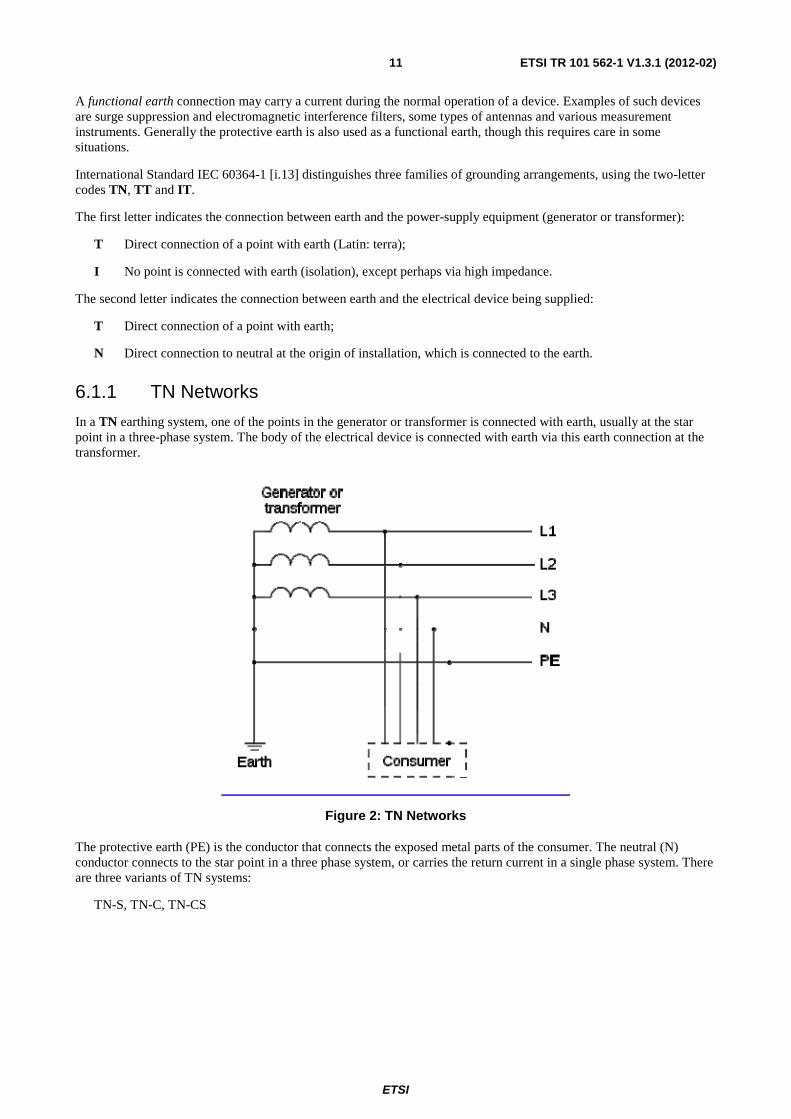
6.1.1 TN Networks
In a TN earthing system, one of the points in the generator or transformer is connected with earth, usually at the star point in a three-phase system. The body of the electrical device is connected with earth via this earth connection at the transformer.
Figure 2: TN Networks
The protective earth (PE) is the conductor that connects the exposed metal parts of the consumer. The neutral (N) conductor connects to the star point in a three phase system, or carries the return current in a single phase system. There are three variants of TN systems:
TN-S, TN-C, TN-CS
ETSI
ETSI TR 101 562-1 V1.3.1 (2012-02)12
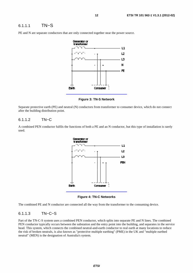
6.1.1.1 TN−S
PE and N are separate conductors that are only connected together near the power source.
Figure 3: TN-S Network
Separate protective earth (PE) and neutral (N) conductors from transformer to consumer device, which do not connect after the building distribution point.
6.1.1.2 TN−C
A combined PEN conductor fulfils the functions of both a PE and an N conductor, but this type of installation is rarely used.
Figure 4: TN-C Networks
The combined PE and N conductor are connected all the way from the transformer to the consuming device.
6.1.1.3 TN−C−S
Part of the TN-C-S system uses a combined PEN conductor, which splits into separate PE and N lines. The combined PEN conductor typically occurs between the substation and the entry point into the building, and separates in the service head. This system, which connects the combined neutral-and-earth conductor to real earth at many locations to reduce the risk of broken neutrals, is also known as "protective multiple earthing" (PME) in the UK and "multiple earthed neutral" (MEN) is the designation of Australia's system.
ETSI
ETSI TR 101 562-1 V1.3.1 (2012-02)13
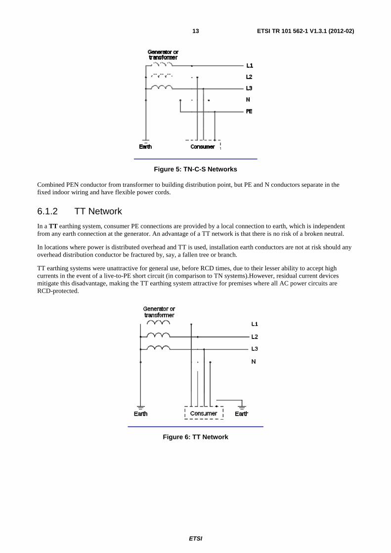
Figure 5: TN-C-S Networks
Combined PEN conductor from transformer to building distribution point, but PE and N conductors separate in the fixed indoor wiring and have flexible power cords.
6.1.2 TT Network
In a TT earthing system, consumer PE connections are provided by a local connection to earth, which is independent from any earth connection at the generator. An advantage of a TT network is that there is no risk of a broken neutral.
In locations where power is distributed overhead and TT is used, installation earth conductors are not at risk should any overhead distribution conductor be fractured by, say, a fallen tree or branch.
TT earthing systems were unattractive for general use, before RCD times, due to their lesser ability to accept high currents in the event of a live-to-PE short circuit (in comparison to TN systems).However, residual current devices mitigate this disadvantage, making the TT earthing system attractive for premises where all AC power circuits are RCD-protected.
Figure 6: TT Network
ETSI
ETSI TR 101 562-1 V1.3.1 (2012-02)14
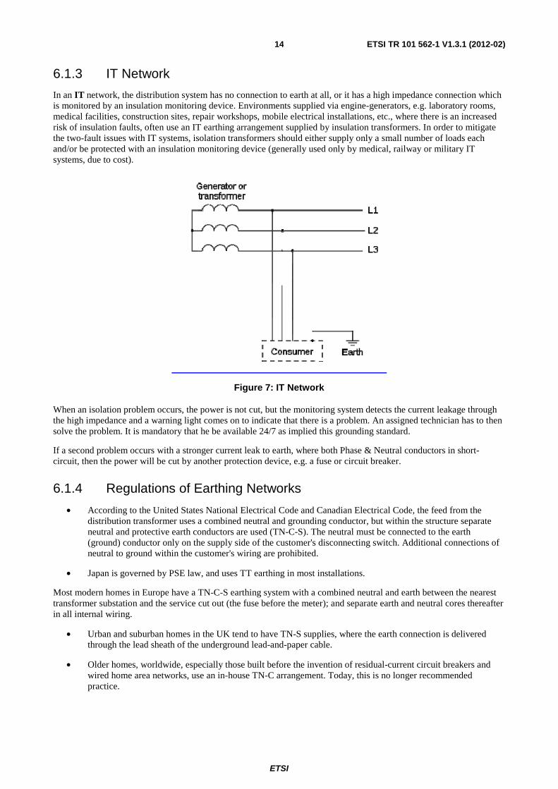
6.1.3 IT Network
In an IT network, the distribution system has no connection to earth at all, or it has a high impedance connection which is monitored by an insulation monitoring device. Environments supplied via engine-generators, e.g. laboratory rooms, medical facilities, construction sites, repair workshops, mobile electrical installations, etc., where there is an increased risk of insulation faults, often use an IT earthing arrangement supplied by insulation transformers. In order to mitigate the two-fault issues with IT systems, isolation transformers should either supply only a small number of loads each and/or be protected with an insulation monitoring device (generally used only by medical, railway or military IT systems, due to cost).
Figure 7: IT Network
When an isolation problem occurs, the power is not cut, but the monitoring system detects the current leakage through the high impedance and a warning light comes on to indicate that there is a problem. An assigned technician has to then solve the problem. It is mandatory that he be available 24/7 as implied this grounding standard.
If a second problem occurs with a stronger current leak to earth, where both Phase & Neutral conductors in short-circuit, then the power will be cut by another protection device, e.g. a fuse or circuit breaker.
6.1.4 Regulations of Earthing Networks
• According to the United States National Electrical Code and Canadian Electrical Code, the feed from the distribution transformer uses a combined neutral and grounding conductor, but within the structure separate neutral and protective earth conductors are used (TN-C-S). The neutral must be connected to the earth (ground) conductor only on the supply side of the customer's disconnecting switch. Additional connections of neutral to ground within the customer's wiring are prohibited.
• Japan is governed by PSE law, and uses TT earthing in most installations.
Most modern homes in Europe have a TN-C-S earthing system with a combined neutral and earth between the nearest transformer substation and the service cut out (the fuse before the meter); and separate earth and neutral cores thereafter in all internal wiring.
• Urban and suburban homes in the UK tend to have TN-S supplies, where the earth connection is delivered through the lead sheath of the underground lead-and-paper cable.
• Older homes, worldwide, especially those built before the invention of residual-current circuit breakers and wired home area networks, use an in-house TN-C arrangement. Today, this is no longer recommended practice.
ETSI
ETSI TR 101 562-1 V1.3.1 (2012-02)15
• In remote areas, where the cost of an additional PE conductor outweighs the cost of a local earth connection, TT networks are commonly used in some countries, especially in older properties or in rural areas, where safety might otherwise be threatened by the fracture of an overhead PE conductor(e.g. by a fallen tree branch). Within areas that mainly utilize TN-C-S systems, individual properties can be seen to have a TT supply, if the property is considered unsuitable for TN-C-S.
• Australia and Israel both use the TN-C-S systems. However, additional wiring rules require that each customer have separate connections to earth via a water pipe bond (where metallic water pipes enter the consumer's premises) and a dedicated earth electrode. In Australia, new installations must also be bonded to the concrete in the foundation in order to reinforce the connection to the earth conductor (AS3000) under areas of the premises which might become wet, such as bathrooms; typically, this increases the earthing size and creates an equipotential plane. It is not uncommon to only find the water pipe bond in older installations, which is allowed to remain as such, until upgrade and renovation work is done, in which case the additional earth electrode must be installed. Protective earth and neutral conductors are combined up until the consumer's neutral link (located on the customer's side of the electricity meter's neutral connection) - beyond this point, the protective earth and neutral conductors are separate.
6.2 Wall Socket Types Used in Various Countries AC power plugs and sockets are devices for connecting removable, electrically operated consumer devices to a power supply.
A plug connects mechanically to a matching socket. Plugs are mostly or completely male, while sockets are mostly or completely female; the plug has protruding prongs or pins that fit into matching slots or holes in the socket. Generally, a plug is the movable connector attached to the power cord of an electrically operated device, and the socket is a fixture on equipment or a building structure. Wall-mounted sockets are also called receptacles, outlets, or power points.
To reduce the risk of electric shock, plug and socket systems can incorporate a variety of safety features. For example, sockets can be designed to accept only compatible plugs and reject all others, whereas others are designed so that a dangerous voltage is never present on an exposed contact. Exposed contacts in some sockets are used for grounding.
Every commonly-used power outlet has two or three wired contacts. The contacts may be steel or brass, and may be plated with zinc, tin, or nickel. Both live and neutral contacts typically carry current from the source to the load and from the load to the source, changing direction 50-60 times per second, since alternating current (AC) is predominantly used in energy distribution networks vs. direct current (DC = unidirectional). However only the neutral contact remains at or very near the voltage potential of the earth, while the potential of the live contact changes sinusoidally, for example -320 V to +320 V (peak-to-peak). Many outlets and plugs also have a third contact for a connection to earth ground, intended to protect against insulation failure of the connected device. A common approach is for electrical sockets to have three holes, which can accommodate either 3-pin earthed or 2-pin non-earthed plugs.
6.2.1 3 Pin Type Sockets
The types B, H, I, J, K and L use PE third pin (type B accepts type A plugs and types H, J, K and L accept type C). The "Europlug" (type C) will fit type E and F sockets, and the earthed type E/F 2-pin plugs will fit type C (and certain hybrid) sockets, without making earthing contact. Types D, G and M plugs are exclusively 3-pin, used for both earthed and non-earthed appliances.

ETSI
ETSI TR 101 562-1 V1.3.1 (2012-02)16
Table 2: Comparison of Sockets
Type Socket standard Power rating Grounded Polarised Fused Insulated pins
A NEMA 1-15 unpolarised 15 A/125 V No No No No
NEMA 1-15 polarised 15 A/125 V No Yes No No
JIS C 8303, Class II 15 A/100 V No No No No
B
NEMA 5-15 15 A/125 V Yes (Note 1) Yes No No
NEMA 5-20 20 A/125 V Yes (Note 1) Yes No No
JIS C 8303, Class I 15 A/100 V Yes (Note 1) Yes No No
C
CEE 7/16 (Europlug) 2.5 A/250 V No No No Yes
CEE 7/17 16 A/250 V No No (Note 1) No No
GOST 7396 C 1 6 A/250 V 16 A/250 V No No No No
D
BS 546 (2 pin) 2 A/250 V 5 A/250 V = BS 4573 No No No No
BS 546 (3 pin) 2 A/250 V 5 A/250 V 15 A/250 V = SABS 164 30 A/250 V
Yes Yes No No
E CEE 7/5 16 A/250 V Yes (Note 1) Yes No No
(Note 1)
F CEE 7/4 (Schuko) 16 A/250 V Yes (Note 1) No No No
(Note 1)
E+F CEE 7/7 16 A/250 V Yes (Note 1)
Yes (Note 3) No No
(Note 1)
G BS 1363, IS 401 & 411, MS 589, SS 145 13 A/230-240 V Yes Yes Yes Yes
H SI 32 16 A/250 V Yes
(Note 3) Yes No No
TIS 166-2549 16 A/250 V Yes Yes No Yes
I AS/NZS 3112
10 A/240 V 15 A/240 V 20 A/240 V 25 A/240 V 32 A/240 V
Yes (Note 1) Yes No Yes
CPCS-CCC 10 A/250 V Yes Yes No No
IRAM 2073 10 A/250 V Yes Yes No No
J SEV 1011 10 A/250 V 16 A/250 V
Yes (Note 1) Yes No No
K Section 107-2-D1 13 A/250 V Yes (Note 1) Yes No No
L CEI 23-16/VII 10 A/250 V 16 A/250 V
Yes (Note 1) No No Yes
- IEC 60906-1 [i.11] (2 pin) 10 A and 20 A/250 V No No No Yes
IEC 60906-1 [i.11] (3 pin) 10 A and 20 A/250 V Yes (Note 1) Yes No Yes
NOTE 1: There are common ungrounded plugs that work with the grounded sockets of this type. NOTE 2: Deep-wall socket prevents human contact with pins. NOTE 3: Plug can only be inserted one way with French socket of type E, but lack of wiring convention means that the
type is not polarized in practice. NOTE 4: There are some CEE 7/17 plugs with a special shape which are polarized when used with the French socket of
type E (mechanically only). NOTE 5: Newer sockets can accept ungrounded Type C Europlugs.
ETSI
ETSI TR 101 562-1 V1.3.1 (2012-02)17
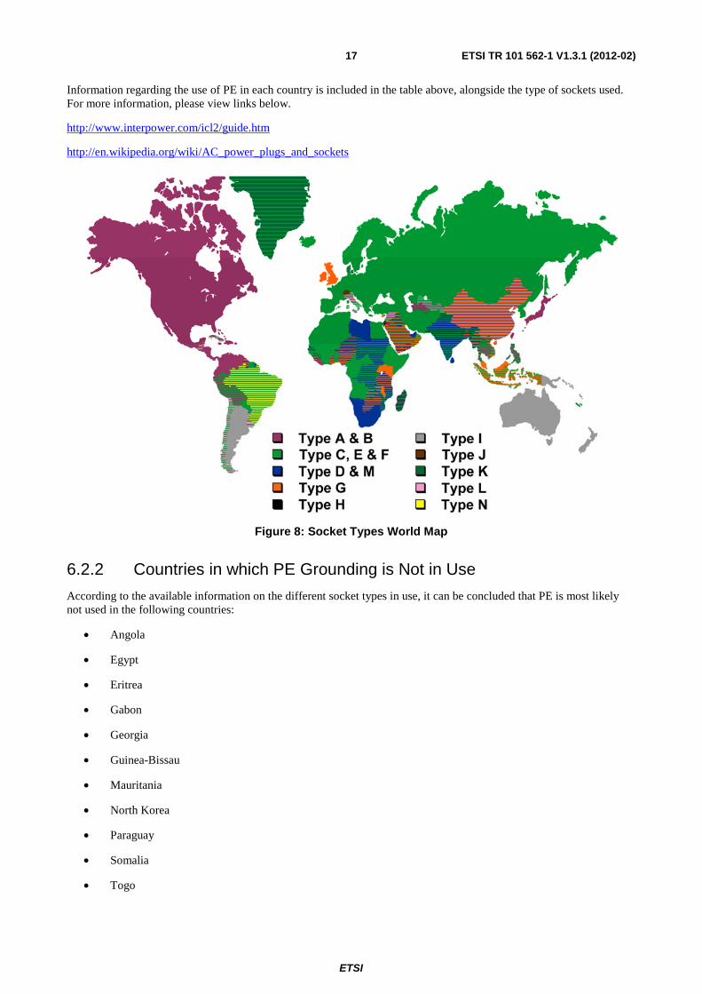
Information regarding the use of PE in each country is included in the table above, alongside the type of sockets used. For more information, please view links below.
http://www.interpower.com/icl2/guide.htm
http://en.wikipedia.org/wiki/AC_power_plugs_and_sockets
Figure 8: Socket Types World Map
6.2.2 Countries in which PE Grounding is Not in Use
According to the available information on the different socket types in use, it can be concluded that PE is most likely not used in the following countries:
• Angola
• Egypt
• Eritrea
• Gabon
• Georgia
• Guinea-Bissau
• Mauritania
• North Korea
• Paraguay
• Somalia
• Togo
ETSI
ETSI TR 101 562-1 V1.3.1 (2012-02)18
6.2.3 Countries where PE Type Sockets are Exclusively Used
It can also be concluded that PE should be exclusively used in the following countries which use D, I, G and J type sockets:
Australia, Bahrain, Bhutan, Botswana, Brunei, Chad, Cook Islands, Cyprus, Dominica, Falkland Islands, Fiji, Gambia, Ghana, Gibraltar, Grenada, Hong Kong, Ireland, Isle of Man, Kenya, Kiribati, Kuwait, Lesotho, Libya, Macau (China), Malawi, Malta, Mauritius, Namibia, Nauru, New Caledonia, New Zealand, Nigeria, Papua New Guinea, Qatar, Reunion Island (France), St Lucia, St Pierre and Miquelon (France), Samoa, Seychelles islands, Sierra Leone, Sri Lanka, Swaziland, Tanzania, Tonga, Turkmenistan, Uganda, United Kingdom, Vanuatu, Zimbabwe.
For these countries, it can be assumed that the percentage of dwellings equipped with Protective Earth wire is high (around 100 %).
6.3 Regulation Approach to Estimate Presence of Protective Earth
In the following clause information from some countries are collected in a harmonized way. Further information on a few countries is given later by STF 410 experts, who have had access to more in depth information. Please see the individual sources for this information.
6.3.1 European Countries
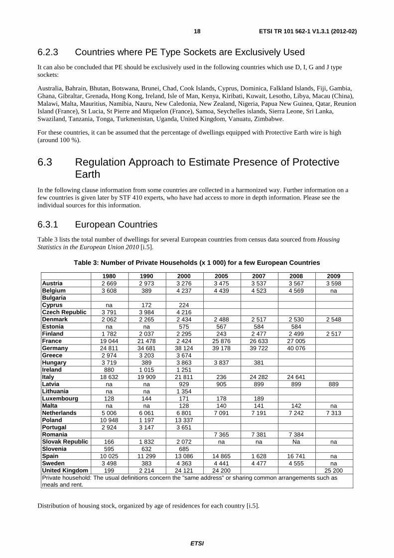
Table 3 lists the total number of dwellings for several European countries from census data sourced from Housing Statistics in the European Union 2010 [i.5].
Table 3: Number of Private Households (x 1 000) for a few European Countries
1980 1990 2000 2005 2007 2008 2009 Austria 2 669 2 973 3 276 3 475 3 537 3 567 3 598 Belgium 3 608 389 4 237 4 439 4 523 4 569 na Bulgaria Cyprus na 172 224 Czech Republic 3 791 3 984 4 216 Denmark 2 062 2 265 2 434 2 488 2 517 2 530 2 548 Estonia na na 575 567 584 584 Finland 1 782 2 037 2 295 243 2 477 2 499 2 517 France 19 044 21 478 2 424 25 876 26 633 27 005 Germany 24 811 34 681 38 124 39 178 39 722 40 076 Greece 2 974 3 203 3 674 Hungary 3 719 389 3 863 3 837 381 Ireland 880 1 015 1 251 Italy 18 632 19 909 21 811 236 24 282 24 641 Latvia na na 929 905 899 899 889 Lithuania na na 1 354 Luxembourg 128 144 171 178 189 Malta na na 128 140 141 142 na Netherlands 5 006 6 061 6 801 7 091 7 191 7 242 7 313 Poland 10 948 1 197 13 337 Portugal 2 924 3 147 3 651 Romania 7 365 7 381 7 384 Slovak Republic 166 1 832 2 072 na na Na na Slovenia 595 632 685 Spain 10 025 11 299 13 086 14 865 1 628 16 741 na Sweden 3 498 383 4 363 4 441 4 477 4 555 na United Kingdom 199 2 214 24 121 24 200 25 200 Private household: The usual definitions concern the "same address" or sharing common arrangements such as meals and rent.
Distribution of housing stock, organized by age of residences for each country [i.5].
ETSI
ETSI TR 101 562-1 V1.3.1 (2012-02)19
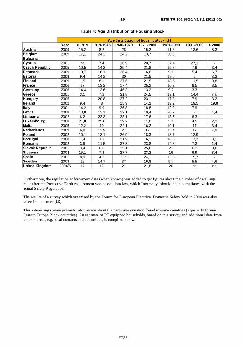
Table 4: Age Distribution of Housing Stock
Age distribution of housing stock (%)
Year < 1919 1919-1945 1946-1970 1971-1980 1981-1990 1991-2000 > 2000 Austria 2009 15,2 8,2 28 15,2 11,5 13,6 8,3 Belgium 2009 17,1 24,2 24,2 13,7 20,8 Bulgaria Cyprus 2001 na 7,4 16,9 20,7 27,4 27,1 - Czech Republic 2005 10,5 14,2 25,4 21,8 15,8 7,9 3,4 Denmark 2009 19,7 16,1 26,4 16,6 9,1 5,4 6,7 Estonia 2009 9,4 14,2 30 21,5 19,6 2 3,3 Finland 2009 1,5 8,1 27,6 21,5 18,5 11,5 9,8 France 2006 17 13,2 17,4 25,2 10,2 8,5 8,5 Germany 2006 14,4 13,6 46,3 13,2 9,2 3,3 Greece 2001 3,1 7,2 31,8 24,5 19,1 14,4 na Hungary 2005 - 20,8 27,2 23,1 17,8 7,9 3,2 Ireland 2002 9,4 8 15,9 14,2 13,2 19,5 19,8 Italy 2001 14,2 9,9 36,8 18,8 12,2 7,9 - Latvia 2008 13,8 13,1 22,1 19,4 20,2 7 4,4 Lithuania 2002 6,2 23,3 33,1 17,6 13,5 6,3 - Luxembourg 2008 21,8 25,6 29,2 11,6 5,1 4,5 2,2 Malta 2005 12,2 10 22,1 16,2 19,1 17 3,4 Netherlands 2009 6,9 13,9 27 17 15,4 12 7,9 Poland 2002 10,1 13,1 26,9 18,3 18,7 12,9 - Portugal 2008 7,4 10 21,9 16,1 18,8 17,7 8,1 Romania 2002 3,9 11,5 37,3 23,8 14,8 7,3 1,4 Slovak Republic 2001 3,4 6,6 35,1 25,6 21 6,2 0,6 Slovenia 2004 15,1 7,8 27,7 23,2 16 6,9 3,4 Spain 2001 8,9 4,2 33,5 24,1 13,6 15,7 - Sweden 2008 12 14,7 37 16,8 9,4 5,5 4,6 United Kingdom 2004/5 17 17 21 21,8 20 na na
Furthermore, the regulation enforcement date (when known) was added to get figures about the number of dwellings built after the Protective Earth requirement was passed into law, which "normally" should be in compliance with the actual Safety Regulation.
The results of a survey which organized by the Forum for European Electrical Domestic Safety held in 2004 was also taken into account [i.5].
This interesting survey presents information about the particular situation found in some countries (especially former Eastern Europe Block countries). An estimate of PE equipped households, based on this survey and additional data from other sources, e.g. local contacts and authorities, is compiled below.
ETSI
ETSI TR 101 562-1 V1.3.1 (2012-02)20
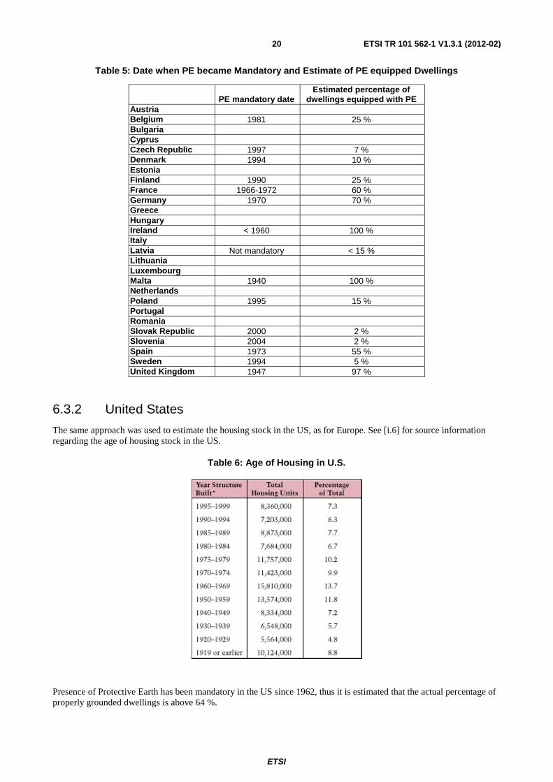
Table 5: Date when PE became Mandatory and Estimate of PE equipped Dwellings
PE mandatory date Estimated percentage of
dwellings equipped with PE Austria Belgium 1981 25 % Bulgaria Cyprus Czech Republic 1997 7 % Denmark 1994 10 % Estonia Finland 1990 25 % France 1966-1972 60 % Germany 1970 70 % Greece Hungary Ireland < 1960 100 % Italy Latvia Not mandatory < 15 % Lithuania Luxembourg Malta 1940 100 % Netherlands Poland 1995 15 % Portugal Romania Slovak Republic 2000 2 % Slovenia 2004 2 % Spain 1973 55 % Sweden 1994 5 % United Kingdom 1947 97 %
6.3.2 United States
The same approach was used to estimate the housing stock in the US, as for Europe. See [i.6] for source information regarding the age of housing stock in the US.
Table 6: Age of Housing in U.S.
Presence of Protective Earth has been mandatory in the US since 1962, thus it is estimated that the actual percentage of properly grounded dwellings is above 64 %.

ETSI
ETSI TR 101 562-1 V1.3.1 (2012-02)21
6.3.3 Canada
The same approach was used to estimate the status in Canada. Source: [i.7].
Table 7: Number and Age of Housing in Canada
Tenure and Period of construction # of households % by age Built after 1960 1945 or before 1 661 635 14,3
1946-1960 1 819 730 15,7 PE mandatory after 1960 1961-1970 1 833 290 15,9 15,9 1971-1980 2 460 455 21,3 21,3 1981-1985 1 001 665 8,7 8,7 1986-1990 1 079 075 9,3 9,3 1991-1995 887 255 7,7 7,7 1996-2001 819 865 7,1 7,1
11 562 970 100 69,9
Presence of Protective Earth has been mandatory since around 1960 (depending on provinces), thus we have estimated the actual percentage of properly grounded dwellings to be above 70 %.
6.3.4 More Detailed Information about a few Countries
6.3.4.1 Presence of PE Wire in Belgium
Figure 9: Number of dwellings erected over time in some European countries

ETSI
ETSI TR 101 562-1 V1.3.1 (2012-02)22
Figure 10: Number of New Dwellings per 1 000 Inhabitants
In Belgium, electrical installations fall under the national regulation of the so called AREI (Algemeen reglement op de Elektrische Installaties). The present document describes the electrical installation including transport of high voltage, distribution, industrial and household installation and is available in Dutch and French only (RGIE).
The present document also outlines the PE and its requirements, how it should behave and how it should be installed (maximum earth resistance, materials, wire sections and colors, installation practices, etc.).
Additional and specific PE requirements may exist according to the "machine directive" in industrial environments.
From 1982 on, a PE has been mandatory for all new installations, but old, and (non-renovated private) houses are exempt (it is estimated that 1,5 million houses in Belgium still do not have a PE, or at least no PE which is "state of the art" and in compliance with AREI regulations).
6.3.4.2 Presence of PE Wire in France
6.3.4.2.1 Historical PE relative standards
This clause presents the main standards related to PE over the past years in France.

ETSI
ETSI TR 101 562-1 V1.3.1 (2012-02)23
Table 8: Historical Development of Standards Requesting Earthing in France
Year Standard Comments
1935 4th August 1935 decree This decree introduces the fact that, due to possible lack of isolation, equipment ground shall be connected to earth. No details regarding earth connector, earth connection. Earthing is not associated to circuit breaker. Not applicable decree due to lack of technical and mechanical information.
1962 Decree 62-1454 November 14th 1962
Main decree that introduced protective earth concept with protection circuit (circuit breaker) and clearly identified PE wire. This decree only applied to electricians working on power supply installation.
1966 Minute 66-32 August 17th 1966
Application of decree 62-1454 for new building: PE wire is mandatory.
1971 SEC/EL n°14 March 10th 1971
Technical note given rules regarding PE installation on new building
1972 UTE 5-120 February 10th 1972
UTE (Electro-technical French standardization) published practical guide of wiring PE wire inside new building. This guide is the technical and practical aspects of the Minute 66-32. PE wire is mandatory and shall be installed according to this guide.
1972 NF C15-120 June 21st 1972
Technical note that give recommendation regarding reinforced concrete that shall be connected to Earth.
From this historical data, we can sum up that the PE wire has been mandatory since 1966, but it is not technically applicable due to lack of recommendations and technical information.
Since 1972 and publication of technical information, new buildings are equipped with common rules for PE wire installations.
6.3.4.2.2 Statistical Data
Now, based on statistical data, we will try to calculate the number of premises equipped with PE wire.
6.3.4.2.2.1 New Housing since 1972
The INSEE (French statistical institute) provides relevant information regarding the number of new residences since 1974 for various countries in Europe. (http://www.insee.fr/fr/ffc/docs_ffc/es343b.pdf)

ETSI
ETSI TR 101 562-1 V1.3.1 (2012-02)24
NOTE: X-axis: Year; Y-axis: Thousands of new housing for different countries.
Figure 11: Number of Dwellings Erected over Time in some European Countries
We can assume an average number of 350 k new residences per year. That means that about 13,3 million residences equipped with PE wiring have been built since 1972.
6.3.4.2.2.2 Average people per housing
The same document from INSEE (http://www.insee.fr/fr/ffc/docs_ffc/es343b.pdf) claims about 2,4 people (average) per new housing.
NOTE: X-axis: Number of People per Household; Y-axis: Number of New Residences per one thousand People.
Figure 12: Number of People per Household vs. Number of New Residences in some European Countries
Based on these figures we can estimate that 2,4*13,3=31,92 million French people live in a PE equipped home.

ETSI
ETSI TR 101 562-1 V1.3.1 (2012-02)25
6.3.4.2.2.3 French Population
According to INSEE (http://www.insee.fr/fr/themes/tableau.asp?reg_id=0&ref_id=NATTEF02133) the French population is about 64 million.
6.3.4.2.2.4 Premises Renovation
We could not find any statistical information related to the renovation of older, privately owned buildings (built before 1972). We only found that roughly 1 % of social premises are renewed per year (http://www.insee.fr/fr/themes/tableau.asp?ref_id=NATnon11413&id=0).
If we suppose that only 0,25 % of the private premises are renewed per year, then, about 10 % of old premises (before 1972) are now equipped with PE wire.
6.3.4.2.2.5 Conclusion of French Wiring Practices
According to the number of new housing since 1972, about 50 % of the French population is equipped with the PE wire.
According to the estimated figure of renovation, 20 % of the French population is living in an old but renewed premise with a PE wire.
So we can estimate that 60 % of the French population is equipped with the PE wire.
6.3.4.3 Presence of PE Wire in Switzerland
Following information given by Electrosuisse:
• Separate wiring of protective earth is mandatory in Switzerland since the 1960's.
• It is believed that more than 90 % (likely more than 95 %) of the apartments are wired this way today.
6.3.4.4 Presence of PE Wire in the US
Following figures (table 9) on housing building permits in the US was found on the web.
ETSI
ETSI TR 101 562-1 V1.3.1 (2012-02)26
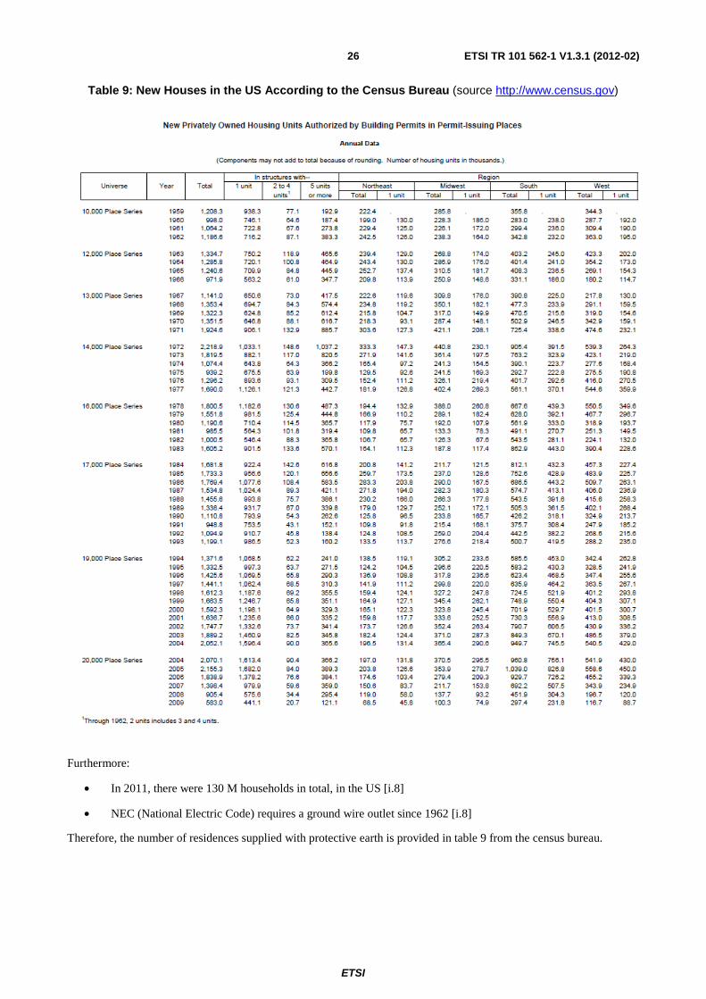
Table 9: New Houses in the US According to the Census Bureau (source http://www.census.gov)
Furthermore:
• In 2011, there were 130 M households in total, in the US [i.8]
• NEC (National Electric Code) requires a ground wire outlet since 1962 [i.8]
Therefore, the number of residences supplied with protective earth is provided in table 9 from the census bureau.
ETSI
ETSI TR 101 562-1 V1.3.1 (2012-02)27
6.3.4.5 Presence of PE Wire in Spain
6.3.4.5.1 Electrical Regulations Data for Spain
The low voltage installations in Spain are regulated by the "Reglamento Electrotécnico para Baja Tensión" (RBT) (Low Voltage Electrotechnical Regulation).
The regulation of internal electrical installations (see note 1) was published on 5th July 1933. This regulation was in effect until 1955 and no further investigation has been done as this regulation does not require the installation of a PE wire inside residences.
In 1955 (see note 2) the RBT was published, effectively overriding the regulation of 1933, and mandatory until 1973. The 1955 version of RBT does not make explicit mention of PE installations inside housing, but states that the metallic parts of several appliances must be earthed: "it is advisable that all the frequently used electrical appliances and placed on tile or cement floor, like kitchen, stove, water boilers, etc., must have its metallic parts earthed."
In 1973 the RBT was revised (see note 3) to include the mandatory installation of PE in low voltage installations for all new housing constructed, as well as for renovated housing where a low voltage installation is present.
As mentioned above, the first regulation requiring the installation of PE appeared in 1973 and was not enforced until the end of December that same year. For this reason, we will take into account that buildings began to have PE installations in new constructions starting in 1974.
NOTE 1: R. 983 y Diccionario 7049 (Regulation 983 and Diccionary 7049).
NOTE 2: Approved by decree of 3rd June of 1955.
NOTE 3: Approved by decree 2413/1973 of 20th September (published in the B.O.E. number 242 of 9th October 1973).
6.3.4.5.2 Spanish Housing Data
The following data has been obtained from the Bank of Spain (www.bde.es) (see note), the Statistics National Institute of Spain (www.ine.es) and the Ministry of Housing of Spain (www.mviv.es).
16 165 923 houses were constructed in the time frame from January 1971 until December 2009.
The total number of houses in Spain at the end of 2009 was 26 768 715.
The average number of houses built per year is 414 511.
NOTE: Except for the figures for 1950 and 1960, these figures have been obtained from the Wikipedia's link: http://es.wikipedia.org/wiki/Anexo:Vivienda_en_España.
ETSI
ETSI TR 101 562-1 V1.3.1 (2012-02)28
Evolution of Housing Stock in Spain (cumulated)
0
5.000.000
10.000.000
15.000.000
20.000.000
25.000.000
30.000.000
1950
1952
1954
1956
1958
1960
1962
1964
1966
1968
1970
1972
1974
1976
1978
1980
1982
1984
1986
1988
1990
1992
1994
1996
1998
2000
2002
2004
2006
2008
Year
Num
ber
of h
ousi
ngs
(cum
ula
Total of housings
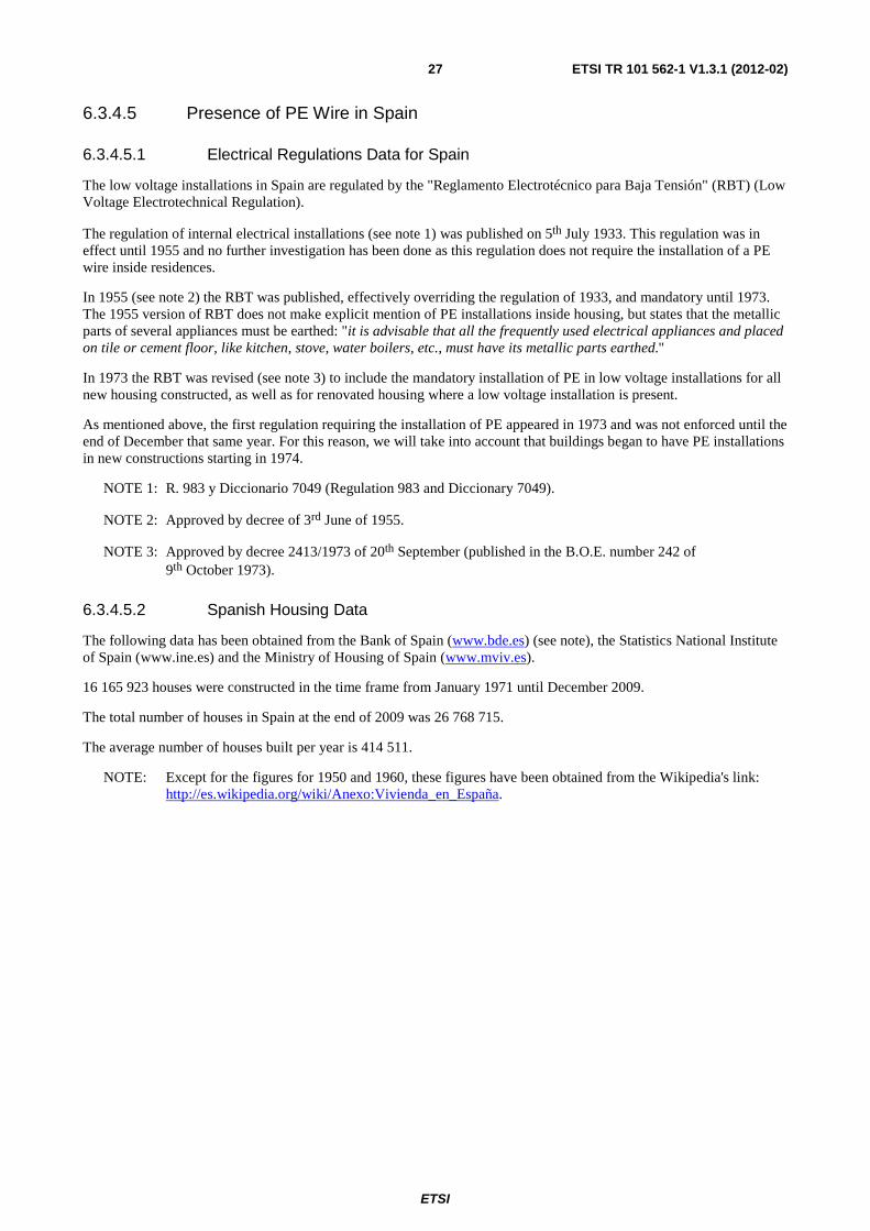
Figure 13: Cumulated Number of New Housing in Spain
Annual Evolution of Housing Stock in Spain
0
100000
200000
300000
400000
500000
600000
700000
800000
900000
1950
1952
1954
1956
1958
1960
1962
1964
1966
1968
1970
1972
1974
1976
1978
1980
1982
1984
1986
1988
1990
1992
1994
1996
1998
2000
2002
2004
2006
2008
Year
Num
ber
of h
ousi
ngs
(cum
ula
Annual Evolution
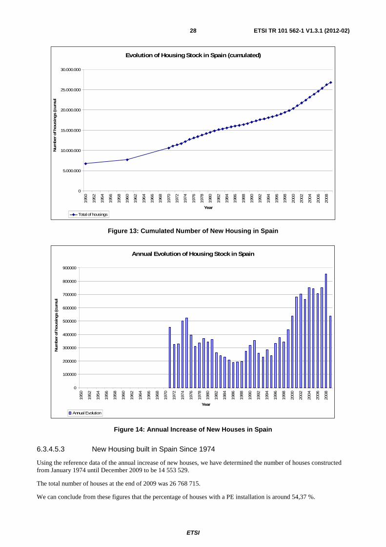
Figure 14: Annual Increase of New Houses in Spain
6.3.4.5.3 New Housing built in Spain Since 1974
Using the reference data of the annual increase of new houses, we have determined the number of houses constructed from January 1974 until December 2009 to be 14 553 529.
The total number of houses at the end of 2009 was 26 768 715.
We can conclude from these figures that the percentage of houses with a PE installation is around 54,37 %.

ETSI
ETSI TR 101 562-1 V1.3.1 (2012-02)29
6.3.4.5.4 Data on Housing Renovations
The data obtained regarding housing renewal and renovation (see note) is more difficult to interpret because the source does not specify whether the electrical wiring was included in the renovation or if the premise already had a PE installation.
NOTE: Data about renewal (housings and buildings) was taken from the statistical information of Ministry of Promotion of Spain (Ministerio de Fomento: www.fomento.es) and Ministry of Housing of Spain (Ministerio de la Vivienda: http://www.mviv.es/).
Renewed Houses
0
5.000
10.000
15.000
20.000
25.000
2000 2001 2002 2003 2004 2005 2006 2007 2008 2009
Years
House
s
Renewed Houses
Figure 15: Renewed Houses in Spain from 2000 to 2009
Data involving building renewal and renovation, although unspecific, is also presented here as it is reasonable to assume, that a percentage of those renewals involve changes to the electrical wiring and PE circuit installations.
Renewed Buildings
0
5.000
10.000
15.000
20.000
25.000
30.000
35.000
40.000
2000 2001 2002 2003 2004 2005 2006 2007 2008 2009
Years
Build
ings
Renewed Buildings
Figure 16: Renewed Buildings in Spain from 2000 to 2009
ETSI
ETSI TR 101 562-1 V1.3.1 (2012-02)30
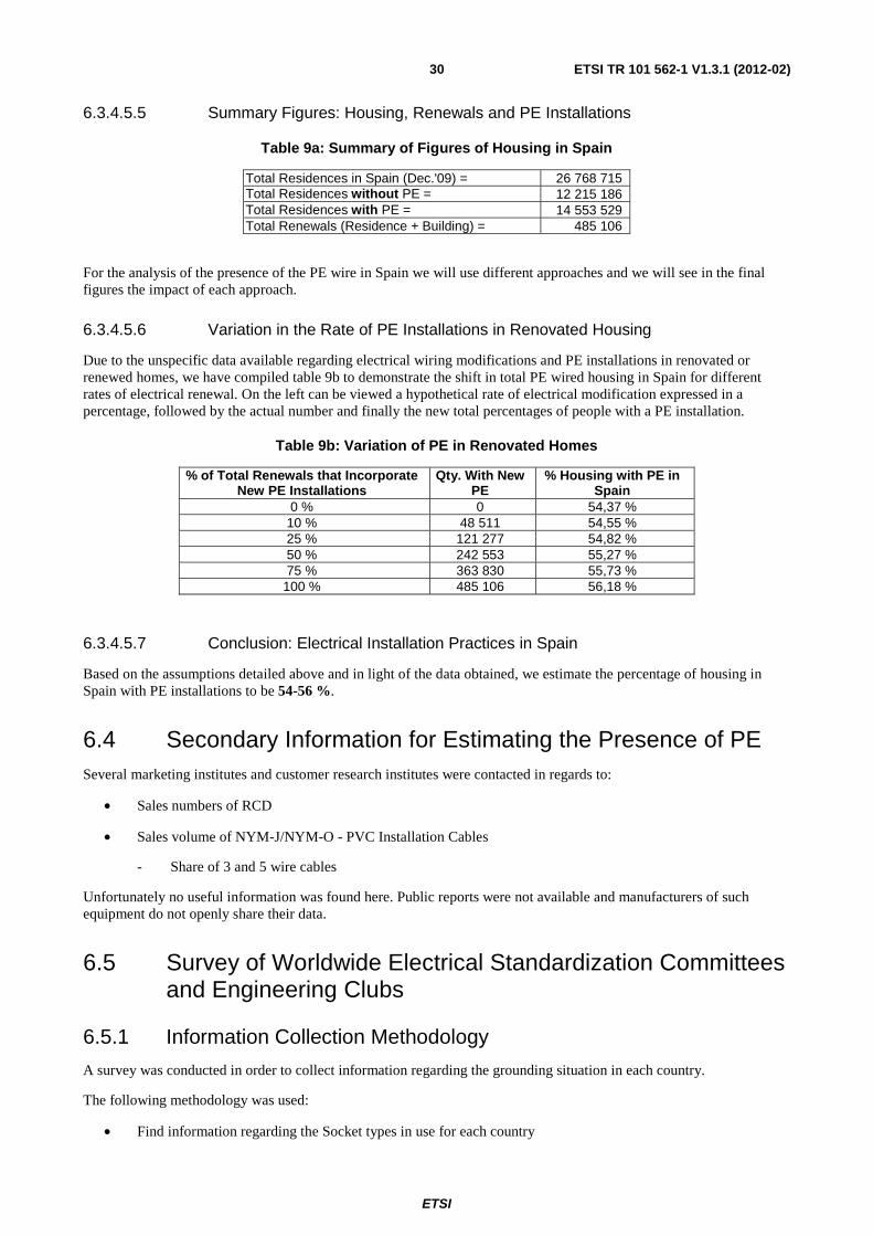
6.3.4.5.5 Summary Figures: Housing, Renewals and PE Installations
Table 9a: Summary of Figures of Housing in Spain
Total Residences in Spain (Dec.'09) = 26 768 715 Total Residences without PE = 12 215 186 Total Residences with PE = 14 553 529 Total Renewals (Residence + Building) = 485 106
For the analysis of the presence of the PE wire in Spain we will use different approaches and we will see in the final figures the impact of each approach.
6.3.4.5.6 Variation in the Rate of PE Installations in Renovated Housing
Due to the unspecific data available regarding electrical wiring modifications and PE installations in renovated or renewed homes, we have compiled table 9b to demonstrate the shift in total PE wired housing in Spain for different rates of electrical renewal. On the left can be viewed a hypothetical rate of electrical modification expressed in a percentage, followed by the actual number and finally the new total percentages of people with a PE installation.
Table 9b: Variation of PE in Renovated Homes
% of Total Renewals that Incorporate New PE Installations
Qty. With New PE
% Housing with PE in Spain
0 % 0 54,37 % 10 % 48 511 54,55 % 25 % 121 277 54,82 % 50 % 242 553 55,27 % 75 % 363 830 55,73 %
100 % 485 106 56,18 %
6.3.4.5.7 Conclusion: Electrical Installation Practices in Spain
Based on the assumptions detailed above and in light of the data obtained, we estimate the percentage of housing in Spain with PE installations to be 54-56 %.
6.4 Secondary Information for Estimating the Presence of PE Several marketing institutes and customer research institutes were contacted in regards to:
• Sales numbers of RCD
• Sales volume of NYM-J/NYM-O - PVC Installation Cables
- Share of 3 and 5 wire cables
Unfortunately no useful information was found here. Public reports were not available and manufacturers of such equipment do not openly share their data.
6.5 Survey of Worldwide Electrical Standardization Committees and Engineering Clubs
6.5.1 Information Collection Methodology
A survey was conducted in order to collect information regarding the grounding situation in each country.
The following methodology was used:
• Find information regarding the Socket types in use for each country

ETSI
ETSI TR 101 562-1 V1.3.1 (2012-02)31
• Cross-check and verify the above data with socket manufacturer's
• Identify countries that exclusively use "3 pin socket types" (probable that the grounding proportion in these countries will be high)
• Identify countries where only "2 pin socket types" are used (No grounding is used)
• Contact member representatives of IEC countries and request them to provide information where available. Following items are requested:
• Is Protective Earth mandatory for new dwellings built in countries worldwide (as of today)?
• Since when? (When was the PE requirement stated into law for each country?)
• What is the proportion (percentage) of dwellings equipped with PE in each country?
• Any statistics regarding the number of older dwellings which do not comply with the grounding requirements.
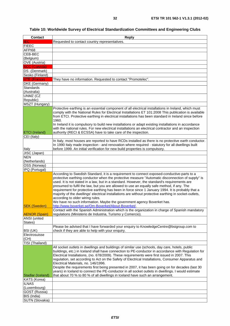
Table 10 shows who was contacted and the reply status.
Color key:
Red: Replied, but no information available.
Orange: Incomplete information was given.
Green: Useful information was provided.
White: Reply Pending.
ETSI
ETSI TR 101 562-1 V1.3.1 (2012-02)32
Table 10: Worldwide Survey of Electrical Standardization Committees and Engineering Clubs Contact Reply
IEC Requested to contact country representatives. FIEEC AFPI68 CEB-BEC (Belgium) OVE (Austria) SCC (Canada) DS -(Denmark) Sesko (Finland) UTE (France) They have no information. Requested to contact "Promotelec". DKE (Germany) Standards (Australia) UNMZ (CZ Republic) MSZT (Hungary)
ETCI (Ireland)
Protective earthing is an essential component of all electrical installations in Ireland, which must comply with the National Rules for Electrical Installations ET 101:2008 This publication is available from ETCI. Protective earthing in electrical installations has been standard in Ireland since before 1960. In Ireland it is compulsory to build new installations or adapt existing installations in accordance with the national rules. For new electrical installations an electrical contractor and an inspection authority (RECI & ECSSA) have to take care of the inspection.
CEI (Italy)
Italy
In Italy, most houses are reported to have RCDs installed as there is no protective earth conductor. In 1990 Italy made inspection - and renovation where required - statutory for all dwellings built before 1999. An initial verification for new build properties is compulsory.
JISC (Japan) NEN (Netherlands) OSS (Norway) IPQ (Portugal)
SEK (Sweden)
According to Swedish Standard, it is a requirement to connect exposed-conductive-parts to a protective earthing conductor when the protective measure "Automatic disconnection of supply" is used. It is not stated in a law, but in a standard. However, the standard's requirements are presumed to fulfil the law, but you are allowed to use an equally safe method, if any. The requirement for protective earthing has been in force since 1 January 1994. It is probably that a majority of the dwellings' electrical installations are without protective earthing in socket-outlets, according to older wiring rules. We have no such information. Maybe the government agency Boverket has. http://www.boverket.se/Om-Boverket/About-Boverket/.
AENOR (Spain) Contact with the Spanish Administration which is the organization in charge of Spanish mandatory regulations (Ministerio de Industria, Turismo y Comercio).
ANSI (united States)
BSI (UK) Please be advised that I have forwarded your enquiry to [email protected] to check if they are able to help with your enquiry.
Electrosuisse (CH) TISI (Thailand)
Stadlar (Iceland)
All socket outlets in dwellings and buildings of similar use (schools, day care, hotels, public buildings, etc.) in Iceland shall have connection to PE-conductor in accordance with Regulation for Electrical Installations, (no. 678/2009). These requirements were first issued in 2007. This regulation, set according to Act on the Safety of Electrical Installations, Consumer Apparatus and Electrical Materials, no. 146/1996. Despite the requirements first being presented in 2007, it has been going on for decades (last 30 years) in Iceland to connect the PE-conductor in all socket outlets in dwellings. I would estimate that about 70 % to 80 % of all dwellings in Iceland have such an arrangement.
KATS (Korea) ILNAS (Luxembourg) GOST (Russia) BIS (India) SUTN (Slovakia)
ETSI
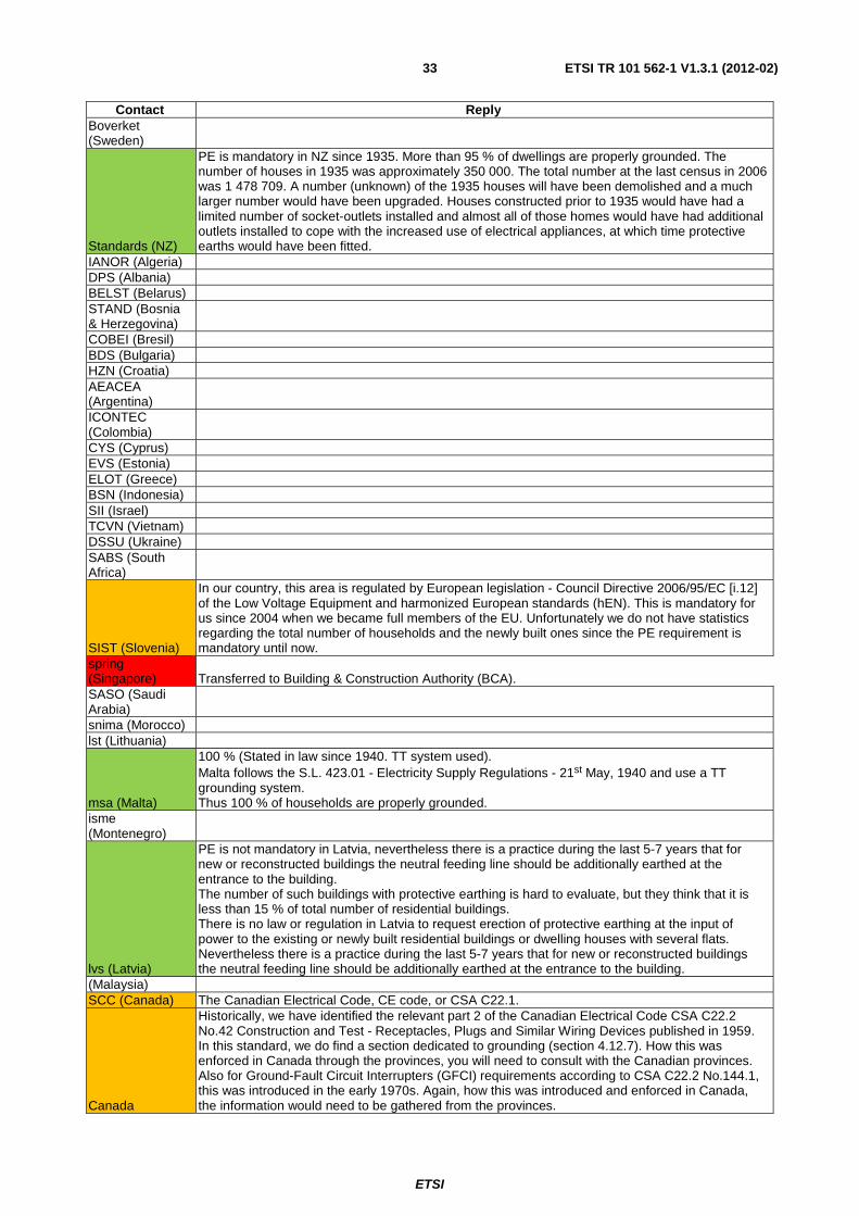
ETSI TR 101 562-1 V1.3.1 (2012-02)33
Contact Reply Boverket (Sweden)
Standards (NZ)
PE is mandatory in NZ since 1935. More than 95 % of dwellings are properly grounded. The number of houses in 1935 was approximately 350 000. The total number at the last census in 2006 was 1 478 709. A number (unknown) of the 1935 houses will have been demolished and a much larger number would have been upgraded. Houses constructed prior to 1935 would have had a limited number of socket-outlets installed and almost all of those homes would have had additional outlets installed to cope with the increased use of electrical appliances, at which time protective earths would have been fitted.
IANOR (Algeria) DPS (Albania) BELST (Belarus) STAND (Bosnia & Herzegovina) COBEI (Bresil) BDS (Bulgaria) HZN (Croatia) AEACEA (Argentina) ICONTEC (Colombia) CYS (Cyprus) EVS (Estonia) ELOT (Greece) BSN (Indonesia) SII (Israel) TCVN (Vietnam) DSSU (Ukraine) SABS (South Africa)
SIST (Slovenia)
In our country, this area is regulated by European legislation - Council Directive 2006/95/EC [i.12] of the Low Voltage Equipment and harmonized European standards (hEN). This is mandatory for us since 2004 when we became full members of the EU. Unfortunately we do not have statistics regarding the total number of households and the newly built ones since the PE requirement is mandatory until now.
spring (Singapore) Transferred to Building & Construction Authority (BCA). SASO (Saudi Arabia) snima (Morocco) lst (Lithuania)
msa (Malta)
100 % (Stated in law since 1940. TT system used). Malta follows the S.L. 423.01 - Electricity Supply Regulations - 21st May, 1940 and use a TT grounding system. Thus 100 % of households are properly grounded.
isme (Montenegro)
lvs (Latvia)
PE is not mandatory in Latvia, nevertheless there is a practice during the last 5-7 years that for new or reconstructed buildings the neutral feeding line should be additionally earthed at the entrance to the building. The number of such buildings with protective earthing is hard to evaluate, but they think that it is less than 15 % of total number of residential buildings. There is no law or regulation in Latvia to request erection of protective earthing at the input of power to the existing or newly built residential buildings or dwelling houses with several flats. Nevertheless there is a practice during the last 5-7 years that for new or reconstructed buildings the neutral feeding line should be additionally earthed at the entrance to the building.
(Malaysia) SCC (Canada) The Canadian Electrical Code, CE code, or CSA C22.1.
Canada
Historically, we have identified the relevant part 2 of the Canadian Electrical Code CSA C22.2 No.42 Construction and Test - Receptacles, Plugs and Similar Wiring Devices published in 1959. In this standard, we do find a section dedicated to grounding (section 4.12.7). How this was enforced in Canada through the provinces, you will need to consult with the Canadian provinces. Also for Ground-Fault Circuit Interrupters (GFCI) requirements according to CSA C22.2 No.144.1, this was introduced in the early 1970s. Again, how this was introduced and enforced in Canada, the information would need to be gathered from the provinces.

ETSI
ETSI TR 101 562-1 V1.3.1 (2012-02)34
Contact Reply
HSE (UK)
The Health and Safety Executive (HSE) are a government body that enforces UK health and safety legislation in the workplace and are concerned with the control of risks to people's health and safety arising from work activities in the UK. The Health and Safety Executive (HSE) has no direct involvement with any requirement for protective earth in domestic properties and so would not hold the information you require.
Inspectapedia (US) NFPA (US) NFPA statistics focuses on FIRE. They do not have stats related to the equipment of households. Consuel (France) Consuel has no statistics about the situation in France. sgs (certification in many countries) EnergieNed (Netherlands) No information (requested to contact NEN). ZVEH (Germany) ESFI (US/Canada) Worldwide? GRESEL (France) Redirected to Promotelec.
France
NFC 15.100 is the French standard. GRESEL & Consuel are important organisations for electrical safety. In France, all houses and flats are required to have RCDs of 500 mA at entry to the installation to protect against fires. French national wiring codes recommend that all properties in France should have a 30 mA RCD installed to protect against the risk of electrocution in bathrooms. Since 1991, it has been obligatory for new electrical installations to be protected against overload and earth leakage currents. It has been estimated that at least one million new homes in France have this type of protection. An initial verification for new build properties is compulsory. Mandatory inspection at change of ownership of electrical installations older than 15 years by law (2010).
Promotelec (France)
Italy
The installation of a protection system has become mandatory in Italy since 1990 (that is, with the entry into force of Law 46/90 on the safety of electrical installations, later replaced by Decree 37/08, which has enlarged the scope of application). With regard to the percentage of non-compliant plants, the available data show that 60 % of homes built before 1990 are not in accordance with (unless of successive restoration) and that currently the properties with non-compliant implants are estimated around 12 million. Difficult to give an exact percentage of total homes since not all properties are intended for residential use, but an estimate could be around 30 %. The earth system used in Italy is TT type. The inspection checks have been provided since 1990, but in reality, due to various reasons, primarily those related to economic aspects, a true check campaign on national basis has never been made.
Spain Complete information provided (see above). Finland See Tukes (Finland). Denmark 10 %. Netherlands
Poland
Found information that the TN-S earthing system is mandatory since beginning of 1995. So all buildings built after that date have additional wire. Before that there was TN-C earthing system with grounding pin bridged to neutral wire in each wall socket. I have also attached the statistics of residential buildings from 1991-2010 period. According to it more than 1,7 M new buildings were built with new system.
Czeck Rep
1) Yes PE is mandatory for new households. It is given by Czech technical standard CSN 332000. 2) Partly it is in force from 1997, the latest update is from 2009. 3) Any official data on proportion are not available, currently it seems that 80 % of dwellings are not equipped with PE.
Hungary Turkey Austria Belgium
Sweden
SEK is responsible for standardisation in Sweden in the field of electricity. The organisation also co-ordinates Swedish participation in European and other international standardisation work as a member of the IEC and CENELEC.

ETSI
ETSI TR 101 562-1 V1.3.1 (2012-02)35
Contact Reply
Tukes (Finland)
It is compulsory now in Finland, and has been from the mid-90's. (Before that it was required only in places with conducting floor and similar, but not in common living rooms or bedrooms.) Old installations can still be repaired and even modified using unearthed (class 0) socket-outlets. No statistics exist on the proportions. A lifetime of a dwelling building is very long, so I would assume that at least more than 50 % are still without protective contact in socket-outlets. Perhaps 70-80 %, as a very rough personal guess. Standardized type used in Finland is the Schuko-type.
dsb (Norway) sik (Denmark) Earthing mandatory for new buildings since April 1st 1994. BCA (Singapore) SGS (Belgium) No stats available about dwellings situation. CEBEC (Belgium) FEEDS contact of the "Towards improved electrical installations in European homes" survey
China
The outlet is either C/A type or I type and the power level is 220V/50Hz. The ratio between2-wire and 3-wire is about 1:1 according to statistics collected from our employee in China office - most houses have these two types of outlets at the same time. Please be advised that, since the number of surveyed houses is quite limited, this ratio in China can only serve as a rough reference only. Unfortunately, there are no official documents at hand for your further reference. In China, the 2-wire and 3-wire outlets always come in pair. In other words, a C/A type and an I type outlet could be found on the same panel. In such circumstances, should we say 50 % or 100 % in China? It depends on interpretation of availability of 3-wire outlet. The Chinese Standard "Design code for residential buildings; GB 50096-1999" specifies how many outlets (incl. the outlet contacts) are mandatory for each room in private homes.
Taiwan
In Taiwan, all outlets in a family home are either 2-wire (A type) for 110V home appliances or 3-wire (H type) for 220V home appliances. The 220V home appliances include refrigerator and air conditioner (i.e. heavy power consumption devices/equipments). All other home appliances use 110V power (i.e. 2-wire) by default. The (A type) is the majority in Taiwan. Note: some 110V power output might use H type as well, depending on request by the family host, for certain purposes. 10 % or less should be fair enough for Taiwan as a statistical probability of meeting a PE wire.
Russia
In Russia and former USSR (and CIS), the country's situation is very unclear and difficult. The Rules of Exploitation of Electro installations (published in 1988, last edited in 1998) said that one of protective countermeasures allowed: x.x.x.x. This document was edited in 1999 and now it includes the clear recommendation to have TN-S or TN-C-S system (even during reconstruction of building). At the same time allowed combining N and PE in five-wires system (in four-wired it is prohibited to combine N and PE). The general idea - we have to increase the degree of harmonization of national situation with worldwide requirements. In the past - (until 1990-th) there was no ground at all. All houses had two-wired mains. Currently - all new buildings (and old ones - during reconstruction) must have four or five-wires mains.
6.6 Worldwide Earthing Situation by Country - an Estimation Table
Table 11 shows the estimated situation regarding the presence of the PE in countries worldwide (based on the available information).
Color key:
Red: Replied, but no information available.
Orange: Incomplete information was given.
Green: Useful information was provided.
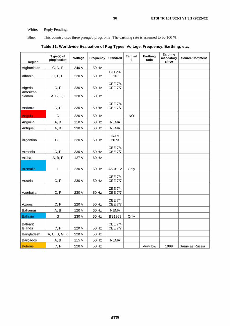
ETSI
ETSI TR 101 562-1 V1.3.1 (2012-02)36
White: Reply Pending.
Blue: This country uses three pronged plugs only. The earthing rate is assumed to be 100 %.
Table 11: Worldwide Evaluation of Pug Types, Voltage, Frequency, Earthing, etc.
Region
Type(s) of plug/socket Voltage Frequency Standard Earthed
? Earthing
ratio
Earthing mandatory
since Source/Comment
Afghanistan C, D, F 240 V 50 Hz
Albania C, F, L 220 V 50 Hz CEI 23-
16
Algeria C, F 230 V 50 Hz CEE 7/4 CEE 7/7
American Samoa A, B, F, I 120 V 60 Hz
Andorra C, F 230 V 50 Hz CEE 7/4 CEE 7/7
Angola C 220 V 50 Hz NO
Anguilla A, B 110 V 60 Hz NEMA
Antigua A, B 230 V 60 Hz NEMA
Argentina C, I 220 V 50 Hz IRAM 2073
Armenia C, F 230 V 50 Hz CEE 7/4 CEE 7/7
Aruba A, B, F 127 V 60 Hz
Australia I 230 V 50 Hz AS 3112 Only
Austria C, F 230 V 50 Hz CEE 7/4 CEE 7/7
Azerbaijan C, F 230 V 50 Hz CEE 7/4 CEE 7/7
Azores C, F 220 V 50 Hz CEE 7/4 CEE 7/7
Bahamas A, B 120 V 60 Hz NEMA
Bahrain G 230 V 50 Hz BS1363 Only
Balearic Islands C, F 220 V 50 Hz
CEE 7/4 CEE 7/7
Bangladesh A, C, D, G, K 220 V 50 Hz
Barbados A, B 115 V 50 Hz NEMA
Belarus C, F 220 V 50 Hz Very low 1999 Same as Russia

ETSI
ETSI TR 101 562-1 V1.3.1 (2012-02)37
Region
Type(s) of plug/socket Voltage Frequency Standard Earthed
? Earthing
ratio
Earthing mandatory
since Source/Comment
Belgium C, E 230 V 50 Hz CEE 7/5 CEE 7/7 25 % 1981
An initial verification for newly built properties is compulsory + 25 years "Periodic Inspection" + mandatory inspection of electrical installations in dwellings at change of ownership from 01.01.07
Belize A, B, G
110 V
60 Hz
and
220 V
Benin C, E 220 V 50 Hz CEE 7/5 CEE 7/7
Bermuda A, B 120 V 60 Hz NEMA
Bhutan D, F, G, M 230 V 50 Hz Only
Bolivia A, C 220 V 50 Hz
Bonaire 127 V 50 Hz
Bosnia C, F 220 V 50 Hz CEE 7/4 CEE 7/7
Botswana D, G, M 230 V 50 Hz Only
Brazil
A, B, C, I - Older C,
NBR14136:2002/
IEC 60906-1 [i.11] - Newer
devices
127 V
60 Hz NBR
14136
2002 ?
and
220 V
Brunei G 240 V 50 Hz BS1363 Only
Bulgaria C, F 230 V 50 Hz CEE 7/4 CEE 7/7
Burkina Faso C, E 220 V 50 Hz CEE 7/5 CEE 7/7
Burundi C, E 220 V 50 Hz CEE 7/5 CEE 7/7
Cambodia A, C, G 230 V 50 Hz
Cameroon C, E 220 V 50 Hz CEE 7/5 CEE 7/7
Canada A, B 120 V 60 Hz NEMA > 70 % 1959 ?
Tbc Canary Islands C, E, F, L 220 V 50 Hz
Cape Verde C, F 220 V 50 Hz CEE 7/4 CEE 7/7
Cayman Islands A, B 120 V 60 Hz NEMA

ETSI
ETSI TR 101 562-1 V1.3.1 (2012-02)38
Region
Type(s) of plug/socket Voltage Frequency Standard Earthed
? Earthing
ratio
Earthing mandatory
since Source/Comment
Central African Republic C, E 220 V 50 Hz
CEE 7/5 CEE 7/7
Chad D, E, F 220 V 50 Hz Only Channel Islands C, G 230 V 50 Hz
Chile C, L 220 V 50 Hz CEI 23-
16
China, People's Republic of A, C, I 220 V 50 Hz
GB1002, GB2099
China, Republic of Taiwan A, B 110 V 60 Hz NEMA
Colombia A, B 120 V 60 Hz NEMA
Comoros C, E 220 V 50 Hz CEE 7/5 CEE 7/7
Congo-Brazzaville C, E 230 V 50 Hz
CEE 7/5 CEE 7/7
Congo-Kinshasa C, D 220 V 50 Hz BS 546
Cook Islands I 240 V 50 Hz AS 3112 Only
Costa Rica A, B 120 V 60 Hz NEMA
Côte d'Ivoire C, E 230 V 50 Hz CEE 7/5 CEE 7/7
Croatia C, F 230 V 50 Hz CEE 7/4 CEE 7/7
Cuba A, B 110 V 60 Hz NEMA
Cyprus G 240 V 50 Hz BS 1363 Only
High (Same as
UK ?)
Czech Republic C, E 230 V 50 Hz
CEE 7/5 CEE 7/7 20 % 1997
Denmark C, E, K 230 V 50 Hz
AFSNIT 107-2-
D1
April 1st 1994 (For
kitchens and bath-
rooms since April
1975)
Djibouti C, E 220 V 50 Hz CEE 7/5 CEE 7/7
Dominica D, G 230 V 50 Hz BS546
BS1363 Only
Dominican Republic A, B 110 V 60 Hz NEMA
East Timor C, E, F, I 220 V 50 Hz
Ecuador A, B 120 V 60 Hz NEMA
Egypt C 220 V 50 Hz NO

ETSI
ETSI TR 101 562-1 V1.3.1 (2012-02)39
Region
Type(s) of plug/socket Voltage Frequency Standard Earthed
? Earthing
ratio
Earthing mandatory
since Source/Comment
El Salvador A, B 115 V 60 Hz NEMA
Equatorial Guinea C, E 220 V 50 Hz
CEE 7/5 CEE 7/7
Eritrea C 230 V 50 Hz NO
Estonia C, F 230 V 50 Hz CEE 7/4 CEE 7/7
Ethiopia C, E, F, L 220 V 50 Hz CEI 23-
16
Faroe Islands C, K 220 V 50 Hz
AFSNIT 107-2-
D1 Falkland Islands G 240 V 50 Hz BS1363 Only
Fiji I 240 V 50 Hz AS 3112 Only
Finland C, F 230 V 50 Hz CEE 7/4 CEE 7/7 > 25 % Mid 1990
France C, E
230 V (formerly 220 V) 50 Hz
CEE 7/5 CEE 7/7 >60 %
Between 1966-1972
French Guiana C, D, E 220 V 50 Hz
Gaza Strip C, H 230 V 50 Hz
Gabon C 220 V 50 Hz No
Gambia G 230 V 50 Hz BS1363 Only
Georgia C 220 V 50 Hz NO
Germany C, F
230 V (formerly 220 V) 50 Hz
CEE 7/4 CEE 7/7 70 % 1970
Ghana D, G 230 V 50 Hz BS546
BS1363 Only
Gibraltar G, K 240 V 50 Hz Only
High (Same as
UK ?)
Greece
C, F, (older)"Tripoliko" similar to type J and post-1989
type H
230 V (formerly 220 V) 50 Hz
Greenland C, K 220 V 50 Hz
AFSNIT 107-2-
D1
Grenada G 230 V 50 Hz BS1363 Only
High (Same as
UK ?)
Guadeloupe C, D, E 230 V 50 Hz CEE 7/5 CEE 7/7
Guam A, B 110 V 60 Hz NEMA
Guatemala A, B 120 V 60 Hz NEMA
Guinea C, F, K 220 V 50 Hz Guinea-Bissau C 220 V 50 Hz NO

ETSI
ETSI TR 101 562-1 V1.3.1 (2012-02)40
Region
Type(s) of plug/socket Voltage Frequency Standard Earthed
? Earthing
ratio
Earthing mandatory
since Source/Comment
Guyana A, B, D, G 240 V 60 Hz
Haiti A, B 110 V 60 Hz NEMA
Honduras A, B 110 V 60 Hz NEMA
Hong Kong
G is used in almost all products, while M is
(rarely) used when
required current rating
is between 13~15A. D is now obsolete
in Hong Kong. 220 V 50 Hz BS 1363 Only
High (Same as
UK ?)
Hungary C, F 230 V 50 Hz CEE 7/4 CEE 7/7
Iceland C, F 230 V 50 Hz CEE 7/4 CEE 7/7
70 %to 80 % 2007
India C, D, M 230 V 50 Hz
IS 1293 BS546
BS1363
Indonesia C, F, G 220 V 50 Hz
Iran C, F 220 V 50 Hz CEE 7/4 CEE 7/7
Iraq C, D, G 230 V 50 Hz
Ireland
G (obsolete or specialist installations may be D
and M (as in the UK) or F)
230 V (formerly 220 V) 50 Hz BS 1363 Only 100 % < 1960
Isle of Man G 240 V 50 Hz BS1363 Only
Israel C, H, M 230 V 50 Hz SI32
Italy C, F, L
230 V (formerly 220 V) 50 Hz
CEI 23-16
Jamaica A, B
110 V and
220 V 50 Hz NEMA
Japan A, B 100 V
50 Hz
JIS C 8303
Low
and
60 Hz
Jordan B, C, D, F, G,
J 230 V 50 Hz
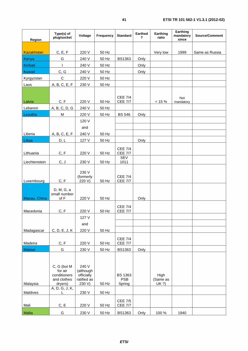
ETSI
ETSI TR 101 562-1 V1.3.1 (2012-02)41
Region
Type(s) of plug/socket Voltage Frequency Standard Earthed
? Earthing
ratio
Earthing mandatory
since Source/Comment
Kazakhstan C, E, F 220 V 50 Hz Very low 1999 Same as Russia
Kenya G 240 V 50 Hz BS1363 Only
Kiribati I 240 V 50 Hz Only
Kuwait C, G 240 V 50 Hz Only
Kyrgyzstan C 220 V 50 Hz
Laos A, B, C, E, F 230 V 50 Hz
Latvia C, F 220 V 50 Hz CEE 7/4 CEE 7/7 < 15 %
Not mandatory
Lebanon A, B, C, D, G 240 V 50 Hz
Lesotho M 220 V 50 Hz BS 546 Only
Liberia A, B, C, E, F
120 V
50 Hz
and
240 V
Libya D, L 127 V 50 Hz Only
Lithuania C, F 220 V 50 Hz CEE 7/4 CEE 7/7
Liechtenstein C, J 230 V 50 Hz SEV 1011
Luxembourg C, F
230 V (formerly 220 V) 50 Hz
CEE 7/4 CEE 7/7
Macau, China
D, M, G, a small number
of F 220 V 50 Hz Only
Macedonia C, F 220 V 50 Hz CEE 7/4 CEE 7/7
Madagascar C, D, E, J, K
127 V
50 Hz
and
220 V
Madeira C, F 220 V 50 Hz CEE 7/4 CEE 7/7
Malawi G 230 V 50 Hz BS1363 Only
Malaysia
C, G (but M for air
conditioners and clothes
dryers)
240 V (although officially
ratified as 230 V) 50 Hz
BS 1363 PSB
Spring
High (Same as
UK ?)
Maldives A, D, G, J, K,
L 230 V 50 Hz
Mali C, E 220 V 50 Hz CEE 7/5 CEE 7/7
Malta G 230 V 50 Hz BS1363 Only 100 % 1940

ETSI
ETSI TR 101 562-1 V1.3.1 (2012-02)42
Region
Type(s) of plug/socket Voltage Frequency Standard Earthed
? Earthing
ratio
Earthing mandatory
since Source/Comment
Martinique C, D, E 220 V 50 Hz CEE 7/5 CEE 7/7
Mauritania C 220 V 50 Hz NO
Mauritius C, G 230 V 50 Hz BS1363 Only
High (Same as
UK ?)
Mexico A, B 127 V 60 Hz NEMA
Micronesia A, B 120 V 60 Hz NEMA
Moldova C, F 220 V 50 Hz CEE 7/4 CEE 7/7
Monaco C, D, E, F
127 V
50 Hz
CEE 7/4 CEE 7/5 CEE 7/7
and
220 V
Mongolia C, E 220 V 50 Hz CEE 7/5 CEE 7/7
Montenegro C, F 220 V 50 Hz CEE 7/4 CEE 7/7
Montserrat (Leeward Is.) A, B 230 V 60 Hz NEMA
Morocco C, E
127 V
50 Hz CEE 7/5 CEE 7/7
and
220 V
Mozambique C, F, M 220 V 50 Hz
Myanmar/Burma C, D, F, G 230 V 50 Hz
Namibia D, M 220 V 50 Hz Only
Nauru I 240 V 50 Hz AS 3112 Only
Nepal C, D, M 230 V 50 Hz
Netherlands C, F
230 V (formerly 220 V) 50 Hz
CEE 7/4 CEE 7/7 1962 ?
Should comply with NEN1010 norm (1st issue 1940, maybe applied from 1962)
Netherlands Antilles A, B, F
127 V
50 Hz
and
220 V
New Caledonia E 220 V 50 Hz
CEE 7/5 CEE 7/7 Only
New Zealand I 230 V 50 Hz AS 3112 Only > 95 % 1935
Nicaragua A, B 120 V 60 Hz NEMA
Niger A, B, C, D, E,
F 220 V 50 Hz
Nigeria D, G 240 V 50 Hz BS546
BS1363 Only
North Korea C 220 V 60 Hz NO
Norway C, F 230 V 50 Hz CEE 7/4
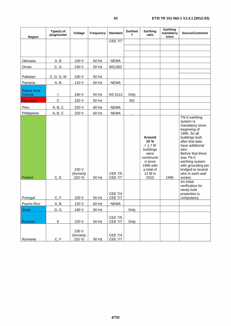
ETSI
ETSI TR 101 562-1 V1.3.1 (2012-02)43
Region
Type(s) of plug/socket Voltage Frequency Standard Earthed
? Earthing
ratio
Earthing mandatory
since Source/Comment
CEE 7/7
Okinawa A, B 100 V 60 Hz NEMA
Oman C, G 240 V 50 Hz BS1363
Pakistan C, D, G, M 230 V 50 Hz
Panama A, B 110 V 60 Hz NEMA
Papua New Guinea I 240 V 50 Hz AS 3112 Only
Paraguay C 220 V 50 Hz NO
Peru A, B, C 220 V 60 Hz NEMA
Philippines A, B, C 220 V 60 Hz NEMA
Poland C, E
230 V (formerly 220 V) 50 Hz
CEE 7/5 CEE 7/7
Around 15 %
> 1,7 M buildings
were constructe
d since 1995 with a total of 12 M in 2010 1995
TN-S earthing system is mandatory since beginning of 1995. So all buildings built after that date have additional wire. Before that there was TN-C earthing system with grounding pin bridged to neutral wire in each wall socket.
Portugal C, F 220 V 50 Hz CEE 7/4 CEE 7/7
An initial verification for newly built properties is compulsory.
Puerto Rico A, B 120 V 60 Hz NEMA
Qatar D, G 240 V 50 Hz Only
Réunion E 220 V 50 Hz CEE 7/5 CEE 7/7 Only
Romania C, F
230 V (formerly 220 V) 50 Hz
CEE 7/4 CEE 7/7

ETSI
ETSI TR 101 562-1 V1.3.1 (2012-02)44
Region
Type(s) of plug/socket Voltage Frequency Standard Earthed
? Earthing
ratio
Earthing mandatory
since Source/Comment
Russian Federation C, F 220 V 50 Hz
GOST 7396
Around 10 %
(only new buildings
since 1999 and
renewed ones if owner
wants to add PE) 1999
Rwanda C, J 230 V 50 Hz SEV 1011
St. Kitts and Nevis A, B, D, G
110 V
60 Hz
and
230 V
St. Lucia (Windward Is.) G 240 V 50 Hz BS1363 Only
High (Same as
UK ?)
Saint Pierre and Miquelon E 230 V 50 Hz
CEE 7/5 CEE 7/7 Only
St. Vincent (Windward Is.)
A, C, E, G, I, K 230 V 50 Hz
High (Same as
UK ?)
Samoa I 230 V 50 Hz AS 3112 Only
São Tomé and Príncipe C, F 220 V 50 Hz
CEE 7/4 CEE 7/7
Saudi Arabia A, B, F, G
127 V
60 Hz SASO 2203
and
220 V
Senegal C, D, E, K 230 V 50 Hz
Serbia C, F 220 V 50 Hz CEE 7/4 CEE 7/7
Seychelles G 240 V 50 Hz BS1363 Only
Sierra Leone D, G 230 V 50 Hz Only
High (Same as
UK ?)
Singapore C, G 230 V 50 Hz
BS 1363 PSB
Spring
High (Same as
UK ?)
Buildings including residential developments must comply with the Singapore Standard SS 555: 2010 - Code of Practice for Protection Against Lightning. I got no information about sockets grounding, so far.
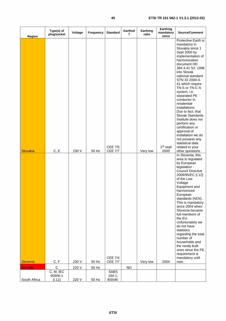
ETSI
ETSI TR 101 562-1 V1.3.1 (2012-02)45
Region
Type(s) of plug/socket Voltage Frequency Standard Earthed
? Earthing
ratio
Earthing mandatory
since Source/Comment
Slovakia C, E 230 V 50 Hz CEE 7/5 CEE 7/7 Very low
1st sept 2000
Protective Earth is mandatory in Slovakia since 1 Sept 2000 by implementation of harmonization document HD 384.4.41 S2: 1996 into Slovak national standard STN 33 2000-4-41 which require TN-S or TN-C-S system, i.e. separated PE conductor in residential installations. Due to fact, that Slovak Standards Institute does not perform any certification or approval of installation we do not possess any statistical data related to your other questions.
Slovenia C, F 230 V 50 Hz CEE 7/4 CEE 7/7 Very low 2004
In Slovenia, this area is regulated by European legislation - Council Directive 2006/95/EC [i.12] of the Low Voltage Equipment and harmonized European standards (hEN) . This is mandatory since 2004 when Slovenia became full members of the EU. Unfortunately we do not have statistics regarding the total number of households and the newly built ones since the PE requirement is mandatory until now.
Somalia C 220 V 50 Hz NO
South Africa
C, M, IEC 60906-1
[i.11] 220 V 50 Hz
SABS 164-1, BS546

ETSI
ETSI TR 101 562-1 V1.3.1 (2012-02)46
Region
Type(s) of plug/socket Voltage Frequency Standard Earthed
? Earthing
ratio
Earthing mandatory
since Source/Comment
South Korea
A, B, C, F (Types A & B are used for
110-volt installations and/or found in very old buildings.
Types C & F are used for 220 Volts.) 220 V 60 Hz
KS C 8305
Spain C, F
230 V (formerly 220 V) 50 Hz
CEE 7/4 CEE 7/7 > 55 % 1973
PE is mandatory in Spain since technical instructions published by the Spanish government at the end of 1973 "Instrucciones RBT 1973". Electrical installations are regulated in the Reglamento Electrotécnico de Baja Tensión (REBT), approved by Real Decreto of august 2 of 2002, and its Complementary Technical Instructions (ITC-BT). PRIE - Platform For Periodic Inspection of Electrical Installations - Draft guide for periodic inspections of electrical installations. An initial verification for newly built properties is compulsory.
Sri Lanka D, M, G 230 V 50 Hz Only
High (Same as
UK ?)
Sudan C, D 230 V 50 Hz
Suriname C, F 127 V 60 Hz CEE 7/4 CEE 7/7
Swaziland M 230 V 50 Hz Only
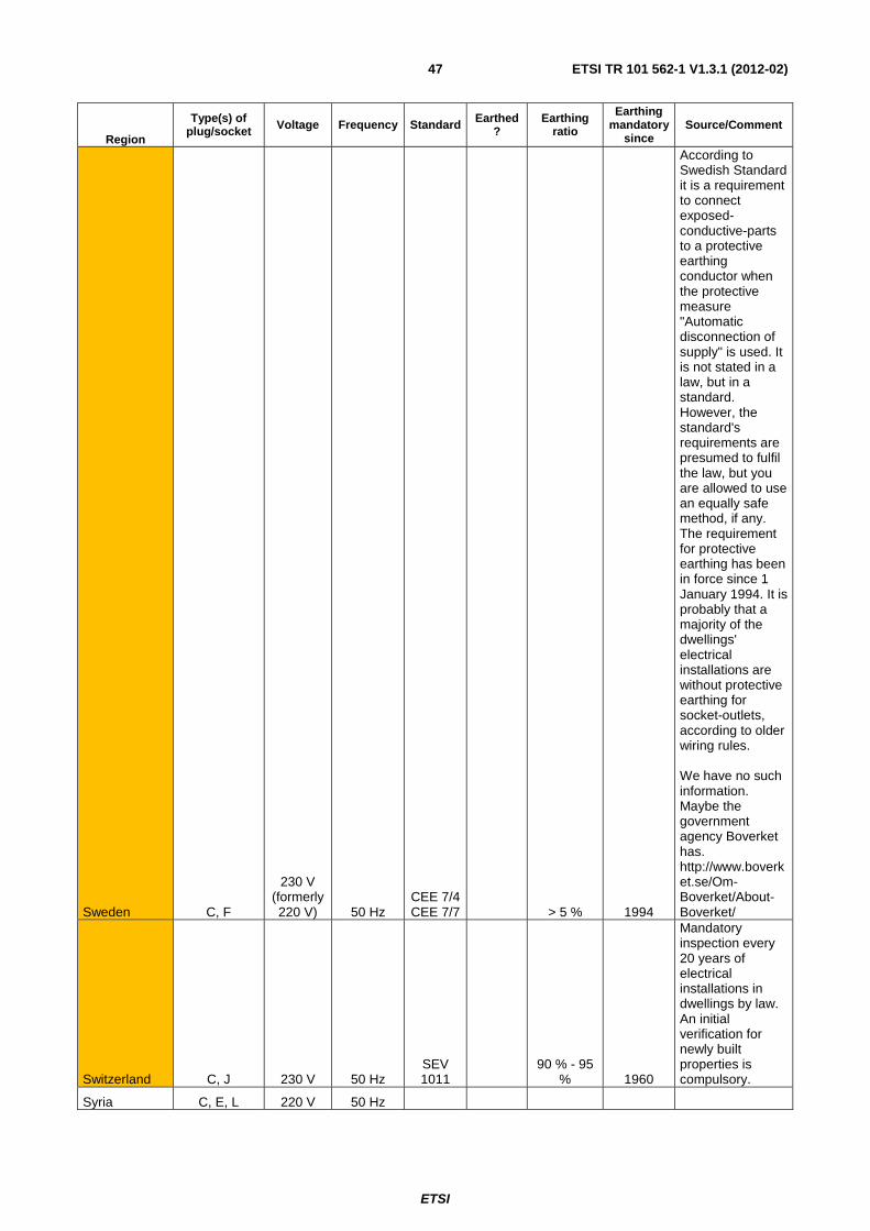
ETSI
ETSI TR 101 562-1 V1.3.1 (2012-02)47
Region
Type(s) of plug/socket Voltage Frequency Standard Earthed
? Earthing
ratio
Earthing mandatory
since Source/Comment
Sweden C, F
230 V (formerly 220 V) 50 Hz
CEE 7/4 CEE 7/7 > 5 % 1994
According to Swedish Standard it is a requirement to connect exposed-conductive-parts to a protective earthing conductor when the protective measure "Automatic disconnection of supply" is used. It is not stated in a law, but in a standard. However, the standard's requirements are presumed to fulfil the law, but you are allowed to use an equally safe method, if any. The requirement for protective earthing has been in force since 1 January 1994. It is probably that a majority of the dwellings' electrical installations are without protective earthing for socket-outlets, according to older wiring rules. We have no such information. Maybe the government agency Boverket has. http://www.boverket.se/Om-Boverket/About-Boverket/
Switzerland C, J 230 V 50 Hz SEV 1011
90 % - 95 % 1960
Mandatory inspection every 20 years of electrical installations in dwellings by law. An initial verification for newly built properties is compulsory.
Syria C, E, L 220 V 50 Hz
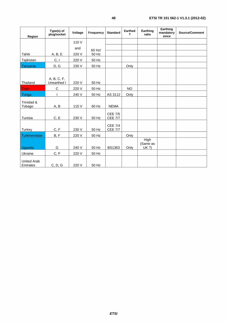
ETSI
ETSI TR 101 562-1 V1.3.1 (2012-02)48
Region
Type(s) of plug/socket Voltage Frequency Standard Earthed
? Earthing
ratio
Earthing mandatory
since Source/Comment
Tahiti A, B, E
110 V
60 Hz/ 50 Hz
and
220 V
Tajikistan C, I 220 V 50 Hz
Tanzania D, G 230 V 50 Hz Only
Thailand A, B, C, F,
Unearthed I 220 V 50 Hz
Togo C 220 V 50 Hz NO
Tonga I 240 V 50 Hz AS 3112 Only
Trinidad & Tobago A, B 115 V 60 Hz NEMA
Tunisia C, E 230 V 50 Hz CEE 7/5 CEE 7/7
Turkey C, F 230 V 50 Hz CEE 7/4 CEE 7/7
Turkmenistan B, F 220 V 50 Hz Only
Uganda G 240 V 50 Hz BS1363 Only
High (Same as
UK ?)
Ukraine C, F 220 V 50 Hz
United Arab Emirates C, D, G 220 V 50 Hz
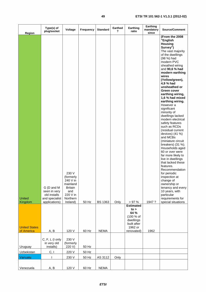
ETSI
ETSI TR 101 562-1 V1.3.1 (2012-02)49
Region
Type(s) of plug/socket Voltage Frequency Standard Earthed
? Earthing
ratio
Earthing mandatory
since Source/Comment
United Kingdom
G (D and M seen in very old installs
and specialist applications)
230 V (formerly 240 V in mainland
Britain and
220 V in Northern Ireland) 50 Hz BS 1363 Only > 97 % 1947 ?
(From the 2008 "English Housing Survey") The vast majority of the dwellings (98 %) had modern PVC sheathed wiring and 90,6 % had modern earthing wires (Yellow/green), 4,9 % had unsheathed or Green cover earthing wiring, 1,6 % had mixed earthing wiring. However a significant minority of dwellings lacked modern electrical safety features such as RCDs (residual current devices) (41 %) and MCBs (miniature circuit breakers) (31 %). Households aged 60 or over were far more likely to live in dwellings that lacked these features. Recommendation for periodic inspection at change of ownership or tenancy and every 10 years, with particular requirements for special situations
United States of America A, B 120 V 60 Hz NEMA
Estimated to > 64 %
(100 % of dwellings built after 1962 or
renovated) 1962
Uruguay
C, F, L (I only in very old
installs)
230 V (formerly 220 V) 50 Hz
Uzbekistan C, I 220 V 50 Hz
Vanuatu I 230 V 50 Hz AS 3112 Only
Venezuela A, B 120 V 60 Hz NEMA

ETSI
ETSI TR 101 562-1 V1.3.1 (2012-02)50
Region
Type(s) of plug/socket Voltage Frequency Standard Earthed
? Earthing
ratio
Earthing mandatory
since Source/Comment
Vietnam A, C, G 220 V 50 Hz
Virgin Islands A, B 110 V 60 Hz NEMA
Yemen A, D, G 230 V 50 Hz
Zambia C, D, G 230 V 50 Hz BS546
BS1363
Zimbabwe D, G 220 V 50 Hz BS546
BS1363 Only
Figure 17 shows the probability of PE wire installations. Countries which exclusively use three pronged plugs (and shaded blue in table 11) are assumed to have 100 % of the outlets equipped with the 3rd wire. Unfortunately, STF410 could not collect any data on countries presented with a white background.
Figure 17: Map showing the Probability of PE Wire Installations
7 Measurement Description of Joint Equipment from Channel, Noise and EMI Measurements
This clause describes the measurement equipment used for all STF410 activities including the channel, Noise and EMI measurements. The special description of the EMI records, how to setup the equipment, how to perform the measurements and the statistical evaluation of the results can be found in TR 101 562-2 [i.9]. A detailed description of the channel and noise records, how to set up the equipment, how to perform the measurements and the statistical evaluation of the results can be found in TR 101 562-3 [i.10].

ETSI
ETSI TR 101 562-1 V1.3.1 (2012-02)51
7.1 MIMO PLT Universal Coupler
Figure 18: Photograph of Coupler from Top
Figure 19: Photograph of Coupler, Case Opened
Figure 18 and figure 19 show photographs of the STF410 coupler from top and with opened case.
7.1.1 Safety Note
• STF 410 MIMO couplers are designed and built with great care.
• STF 410 couplers have to be used exclusively for tests carried out by instructed personnel.
• It is recognized that the connection of the Protective Earth of the STF 410 MIMO couplers does not comply with safety standards for commercial products.
• For best protection of the connected instruments, it is recommended:
- to first switch off all interfaces;
- then to connect the instruments;
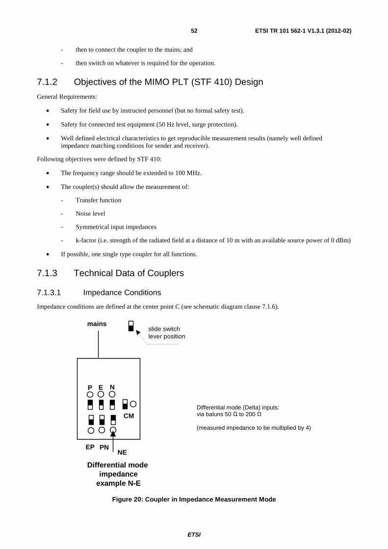
ETSI
ETSI TR 101 562-1 V1.3.1 (2012-02)52
- then to connect the coupler to the mains; and
- then switch on whatever is required for the operation.
7.1.2 Objectives of the MIMO PLT (STF 410) Design
General Requirements:
• Safety for field use by instructed personnel (but no formal safety test).
• Safety for connected test equipment (50 Hz level, surge protection).
• Well defined electrical characteristics to get reproducible measurement results (namely well defined impedance matching conditions for sender and receiver).
Following objectives were defined by STF 410:
• The frequency range should be extended to 100 MHz.
• The coupler(s) should allow the measurement of:
- Transfer function
- Noise level
- Symmetrical input impedances
- k-factor (i.e. strength of the radiated field at a distance of 10 m with an available source power of 0 dBm)
• If possible, one single type coupler for all functions.
7.1.3 Technical Data of Couplers
7.1.3.1 Impedance Conditions
Impedance conditions are defined at the center point C (see schematic diagram clause 7.1.6).
P E N
EPNE
PN
CM
Differential mode impedance
example N-E
mainsslide switchlever position
Differential mode (Delta) inputs: via baluns 50 Ω to 200 Ω (measured impedance to be multiplied by 4)
Figure 20: Coupler in Impedance Measurement Mode

ETSI
ETSI TR 101 562-1 V1.3.1 (2012-02)53
Common Mode (CM) inputs:
• via balun 50 Ω to 200 Ω.
Star inputs (P, N, E):
• direct 50 Ω in each leg.
Characteristic impedance of mains cable, third conductor open circuited:
• approximately 80 Ω.
Characteristic impedance of common mode transformer windings:
• third conductor open circuited:
- approximately 80 Ω.
Test pad: A test or calibration pad was realized to verify impedances of the probes.
Figure 21: Test pad: Schematic and Photo
Characteristic impedance of test pad, (without cables and Schuko connectors):
• third connection open circuited:
- 80 Ω.
7.1.3.2 Insertion Loss
See measurement results in clause 7.1.6.
7.1.4 Operation
The following figures show the connections to MIMO sender and receiver and the position of the slide switches for the different operation modes.
7.1.4.1 SISO Transmit and SISO Receive (Example P-N to P-N)
The setup to connect two couplers in SISO mode is shown below.

ETSI
ETSI TR 101 562-1 V1.3.1 (2012-02)54
SISO PN
P E N P E N
EP NE
PN
IN OUT
PN
EP NE
CM CM
slide switchlever position
channel
SISO transmit / receive P-N
Figure 22: Coupler in SISO Attenuation Measurement Mode
7.1.4.2 MIMO Symmetric Transmit (Example N-E), MIMO Receive Star Plus CM
Figure 23 shows the setup to connect two couplers in a MIMO example mode.
MIMO sym transmit N-E
P E N
P E N
EP NE
PNSender
PNEP NE
CMCM
50 50
channel
Rec
eive
r
slide switchlever position
Figure 23: Coupler in MIMO Symmetric Transmit and MIMO Receive (Star Plus CM) Mode
7.1.4.3 MIMO Asymmetric Transmit (Example N-E), MIMO Receive Star Plus CM
Figure 24 shows the setup to connect two couplers in a MIMO example mode where one port is not terminated.
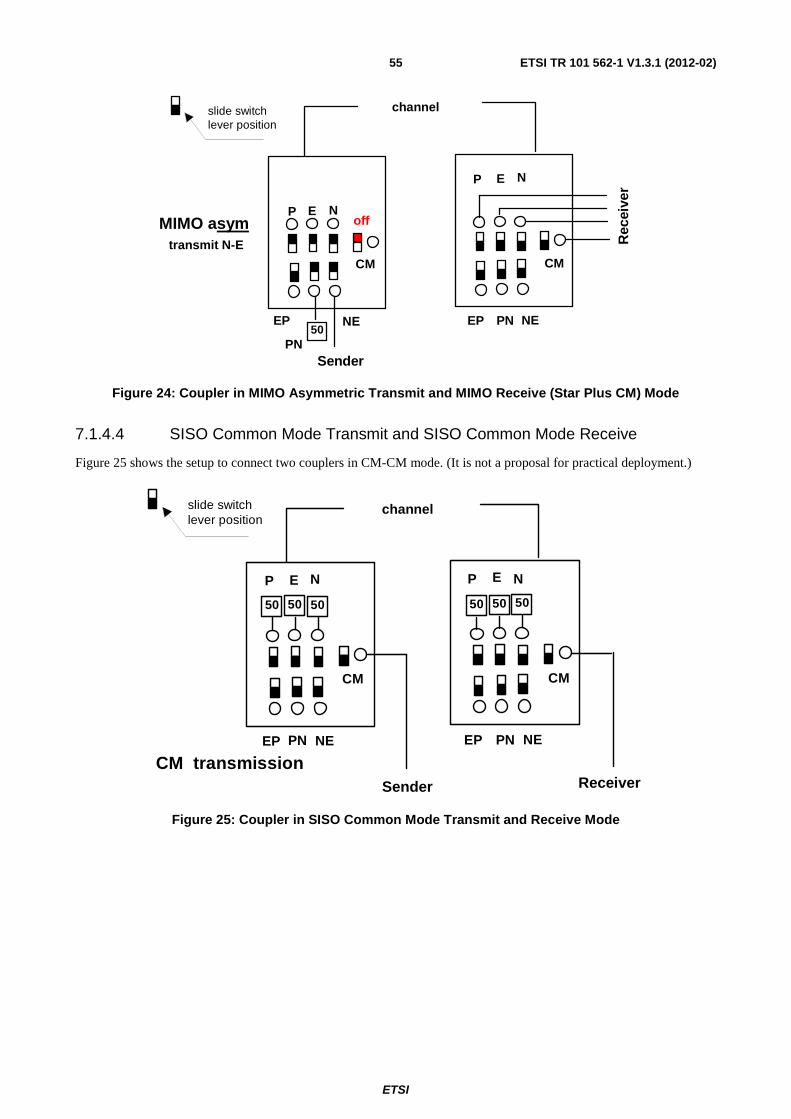
ETSI
ETSI TR 101 562-1 V1.3.1 (2012-02)55
MIMO asym transmit N-E
P E N
P E N
EP NE
PNSender
PNEP NE
CMCM
50
channel
Rec
eive
r
off
slide switchlever position
Figure 24: Coupler in MIMO Asymmetric Transmit and MIMO Receive (Star Plus CM) Mode
7.1.4.4 SISO Common Mode Transmit and SISO Common Mode Receive
Figure 25 shows the setup to connect two couplers in CM-CM mode. (It is not a proposal for practical deployment.)
CM transmission
P E N P E N
EP NEPN
Sender
PNEP NE
CMCM
channel
Receiver
50 50 50 50 50 50
slide switchlever position
Figure 25: Coupler in SISO Common Mode Transmit and Receive Mode

ETSI
ETSI TR 101 562-1 V1.3.1 (2012-02)56
7.1.4.5 Alternative MIMO Mode Using Dual Wire Feed
Figure 26: Coupler in Dual Wire Feed Mode
Version A:
• The short circuit between P and N is not perfect, because the balun represents a transmission line of about 34 cm of electrical length and Zo = 200 Ω at the secondary. At 30 MHz P and N are "shorted" with about j 43 Ω, at 80 MHz with j 115 Ω.
Version B:
• There is enough space inside the Schuko plug of the coupler, to mount a 4,7 nF capacitor inside. For frequencies above 5 MHz this type of short circuit is more effective. The internal coupling to the open third wire is small due to the symmetric construction of the coupler. It should be negligible.
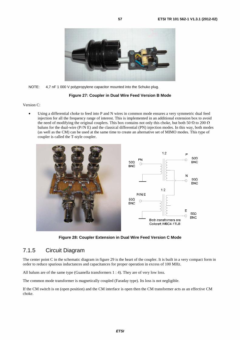
ETSI
ETSI TR 101 562-1 V1.3.1 (2012-02)57
NOTE: 4,7 nF 1 000 V polypropylene capacitor mounted into the Schuko plug.
Figure 27: Coupler in Dual Wire Feed Version B Mode
Version C:
• Using a differential choke to feed into P and N wires in common mode ensures a very symmetric dual feed injection for all the frequency range of interest. This is implemented in an additional extension box to avoid the need of modifying the original couplers. This box contains not only this choke, but both 50 Ω to 200 Ω baluns for the dual-wire (P//N E) and the classical differential (PN) injection modes. In this way, both modes (as well as the CM) can be used at the same time to create an alternative set of MIMO modes. This type of coupler is called the T-style coupler.
Figure 28: Coupler Extension in Dual Wire Feed Version C Mode
7.1.5 Circuit Diagram
The center point C in the schematic diagram in figure 29 is the heart of the coupler. It is built in a very compact form in order to reduce spurious inductances and capacitances for proper operation in excess of 100 MHz.
All baluns are of the same type (Guanella transformers 1 : 4). They are of very low loss.
The common mode transformer is magnetically coupled (Faraday type). Its loss is not negligible.
If the CM switch is on (open position) and the CM interface is open then the CM transformer acts as an effective CM choke.

ETSI
ETSI TR 101 562-1 V1.3.1 (2012-02)58
If the CM switch is off (closed position) then the impedance of the common mode transformer is decreased. The instruments connected to the coupler are protected in several ways:
• gas discharge and varistor between P and N;
• surge protection diodes on P, N and PE;
• switches S1 to S7 that allow the instruments to disconnect.

ETSI
ETSI TR 101 562-1 V1.3.1 (2012-02)59
Universal SISO / MIMO Coupler
4.7nDE37-501M
820k
820k
P
ERZ-V07D471
NPE
3x
BNC50 Ohm
BNC
P
N
E
Schuko
T4
CM
4 t
4 t
4 t
3 x50
Ohm
4.7n
4.7n
GBLC08C-LF
BNC
50Ohm
BNC
50Ohm
BNC
50Ohm
E-P
N-E
P-N
4 t
T4
S7
balun 50 / 200 Ohm
balun 50 / 200 Ohm
balun 50 / 200 Ohm
balun 50 / 200 Ohm
Mains
TR
AN
SM
IT in
terf
ace
(Del
ta)
RE
CE
IVE
inte
rfac
e (s
tar)
cable 1 m3 x 1 mm 2
S1
S2
S3
T1
T2
T3
7 t
7 t
2.2k
2.2k
2.2k
18p
18p
18p
S4
S5
S6
C
CM on
3 x 150
3 x 150
3 x 180
DM calibration pad 20 dB Zo = 80 Ohm
STF 410
7 t
CM - interface(common mode)
on
on
on
on
on
on
common mode transformer
Figure 29: Coupler Schematic

ETSI
ETSI TR 101 562-1 V1.3.1 (2012-02)60
7.1.6 Measurement Results of STF410 Coupler Verification
7.1.6.1 SISO
Figure 30 shows the coupler's verification setup for SISO.
SISO PN
P E N P E N
EP NE
PN
IN OUT
PN
EP NE
CM CM
19.2 dB
Zo = 80 Ohm
Insertion loss with ideal coupler:
total: a = 21,0 dB
Excess insertion loss per coupler:
3 MHz < 0,4 dB
30 MHz < 0,3 dB
60 MHz < 0,5 dB
80 MHz < 0,7 dB
100 MHz < 2,4 dB
Figure 30: Coupler Settings: SISO
Table 12
Coupler Pad
MHz 3 10 30 60 80 100
01 to 02 -S21 PN-PN (dB) 21,7 21,7 21,4 21,8 23,5 25,2 A -S21 NE-NE (dB) 21,7 21,8 21,5 21,7 22,6 24,1 -S21 EP-EP (dB) 21,8 21,8 21,6 21,8 22,6 24,2
03 to 04 -S21 PN-PN (dB) 21,7 21,7 21,5 21,9 23,3 25,3 B -S21 NE-NE (dB) 21,8 21,8 21,5 21,6 22,6 24,2 -S21 EP-EP (dB) 21,8 21,8 21,6 21,7 22,4 24,1
05 to 06 -S21 PN-PN (dB) 21,8 21,8 21,5 21,9 23,6 25,7 C -S21 NE-NE (dB) 21,8 21,8 21,6 21,8 22,8 24,4 -S21 EP-EP (dB) 21,8 21,8 21,7 21,9 22,7 24,1
07 to 08 -S21 PN-PN (dB) 21,7 21,7 21,4 21,7 23,0 24,9 D -S21 NE-NE (dB) 21,7 21,8 21,5 21,5 22,3 23,8 -S21 EP-EP (dB) 21,8 21,8 21,7 21,8 22,3 23,6
09 to 10 -S21 PN-PN (dB) 21,7 21,7 21,4 21,9 23,3 24,3 E -S21 NE-NE (dB) 21,8 21,7 21,5 21,4 22,1 23,5 -S21 EP-EP (dB) 21,8 21,8 21,7 21,7 22,3 23,7
11 to 12 -S21 PN-PN (dB) 21,7 21,7 21,4 21,9 23,3 25,3 F -S21 NE-NE (dB) 21,8 217 21,5 21,4 22,1 23,5 -S21 EP-EP (dB) 21,8 21,8 21,7 21,8 22,3 23,7
13 to 14 -S21 PN-PN (dB) 21,8 21,8 21,5 21,9 23,3 25,2 G -S21 NE-NE (dB) 21,8 218 21,6 21,6 22,2 23,6 -S21 EP-EP (dB) 21,8 21,8 21,7 21,9 22,6 24,0
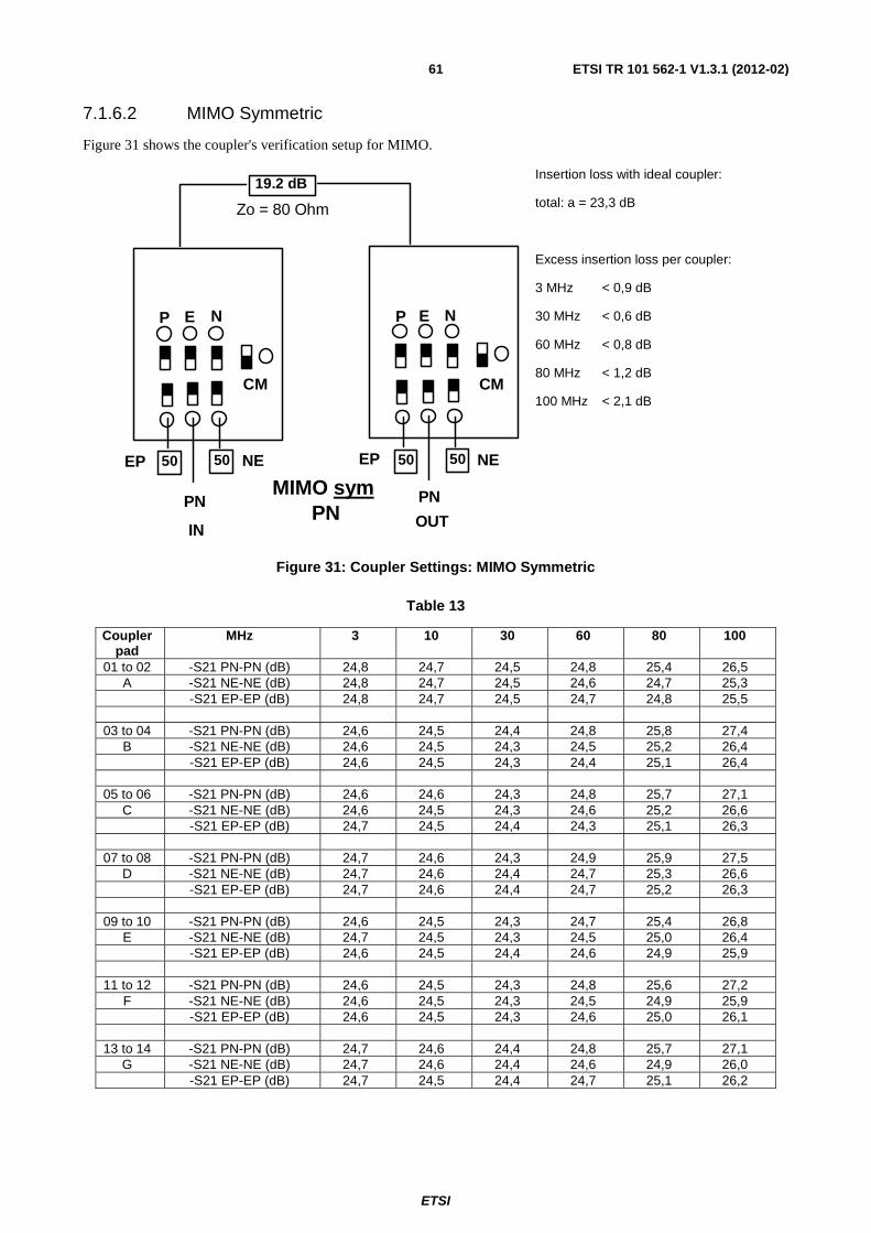
ETSI
ETSI TR 101 562-1 V1.3.1 (2012-02)61
7.1.6.2 MIMO Symmetric
Figure 31 shows the coupler's verification setup for MIMO.
MIMO sym PN
50 5050 50
P E N P E N
EP NE
PN
IN OUT
PN
EP NE
CM CM
19.2 dB
Zo = 80 Ohm
Insertion loss with ideal coupler:
total: a = 23,3 dB
Excess insertion loss per coupler:
3 MHz < 0,9 dB
30 MHz < 0,6 dB
60 MHz < 0,8 dB
80 MHz < 1,2 dB
100 MHz < 2,1 dB
Figure 31: Coupler Settings: MIMO Symmetric
Table 13
Coupler pad
MHz 3 10 30 60 80 100
01 to 02 -S21 PN-PN (dB) 24,8 24,7 24,5 24,8 25,4 26,5 A -S21 NE-NE (dB) 24,8 24,7 24,5 24,6 24,7 25,3 -S21 EP-EP (dB) 24,8 24,7 24,5 24,7 24,8 25,5
03 to 04 -S21 PN-PN (dB) 24,6 24,5 24,4 24,8 25,8 27,4 B -S21 NE-NE (dB) 24,6 24,5 24,3 24,5 25,2 26,4 -S21 EP-EP (dB) 24,6 24,5 24,3 24,4 25,1 26,4
05 to 06 -S21 PN-PN (dB) 24,6 24,6 24,3 24,8 25,7 27,1 C -S21 NE-NE (dB) 24,6 24,5 24,3 24,6 25,2 26,6 -S21 EP-EP (dB) 24,7 24,5 24,4 24,3 25,1 26,3
07 to 08 -S21 PN-PN (dB) 24,7 24,6 24,3 24,9 25,9 27,5 D -S21 NE-NE (dB) 24,7 24,6 24,4 24,7 25,3 26,6 -S21 EP-EP (dB) 24,7 24,6 24,4 24,7 25,2 26,3
09 to 10 -S21 PN-PN (dB) 24,6 24,5 24,3 24,7 25,4 26,8 E -S21 NE-NE (dB) 24,7 24,5 24,3 24,5 25,0 26,4 -S21 EP-EP (dB) 24,6 24,5 24,4 24,6 24,9 25,9
11 to 12 -S21 PN-PN (dB) 24,6 24,5 24,3 24,8 25,6 27,2 F -S21 NE-NE (dB) 24,6 24,5 24,3 24,5 24,9 25,9 -S21 EP-EP (dB) 24,6 24,5 24,3 24,6 25,0 26,1
13 to 14 -S21 PN-PN (dB) 24,7 24,6 24,4 24,8 25,7 27,1 G -S21 NE-NE (dB) 24,7 24,6 24,4 24,6 24,9 26,0 -S21 EP-EP (dB) 24,7 24,5 24,4 24,7 25,1 26,2
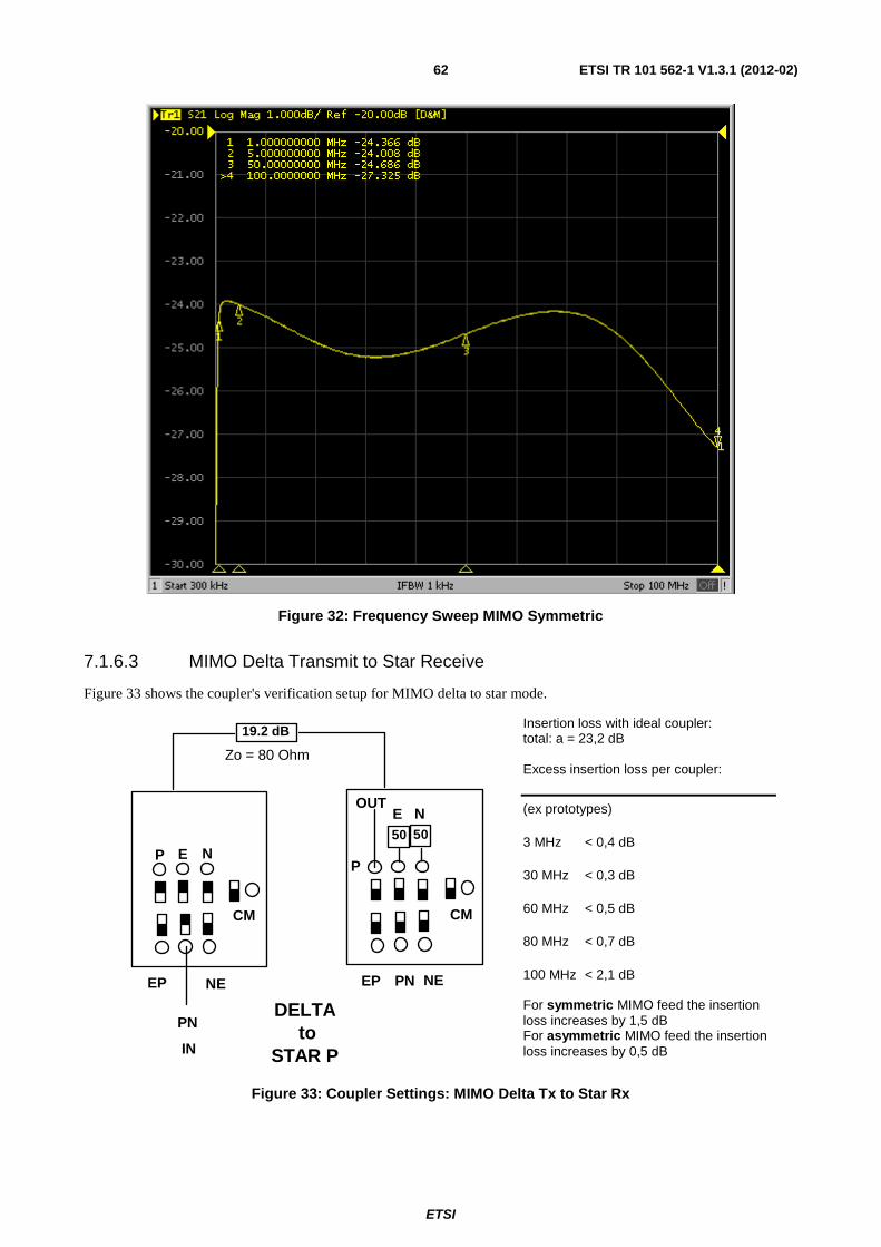
ETSI
ETSI TR 101 562-1 V1.3.1 (2012-02)62
Figure 32: Frequency Sweep MIMO Symmetric
7.1.6.3 MIMO Delta Transmit to Star Receive
Figure 33 shows the coupler's verification setup for MIMO delta to star mode.
DELTA to
STAR P
P E NP
E N
EP NE
PN
IN
OUT
PNEP NE
50 50
CMCM
19.2 dB
Zo = 80 Ohm
Insertion loss with ideal coupler: total: a = 23,2 dB Excess insertion loss per coupler:
(ex prototypes)
3 MHz < 0,4 dB
30 MHz < 0,3 dB
60 MHz < 0,5 dB
80 MHz < 0,7 dB
100 MHz < 2,1 dB For symmetric MIMO feed the insertion loss increases by 1,5 dB For asymmetric MIMO feed the insertion loss increases by 0,5 dB
Figure 33: Coupler Settings: MIMO Delta Tx to Star Rx

ETSI
ETSI TR 101 562-1 V1.3.1 (2012-02)63
Table 14
Coupler pad
MHz 3 10 30 60 80 100
01 to 02 -S21 PN to P (dB) 25,4 25,2 25,3 25,5 26,7 27,3 A -S21 PN to N (dB) 25,4 25,3 25,3 25,2 26,3 26,8
prototype -S21 PN to E (dB) 69 67 63 59 58 56
03 to 04 -S21 PN to P (dB) 23,7 23,7 23,5 24,5 25,6 27,2 B -S21 PN to N (dB) 23,9 23,9 23,5 24,3 25,6 27,3 -S21 PN to E (dB) 58 57 51 44 43 42
05 to 06 -S21 PN to P (dB) 23,7 23,7 23,6 24,5 25,3 26,8 C -S21 PN to N (dB) 23,9 23,9 23,6 24,3 25,4 26,9 -S21 PN to E (dB) 58 59 54 44 43 44
07 to 08 -S21 PN to P (dB) 23,8 23,7 23,7 24,5 25,8 27,4 D -S21 PN to N (dB) 24,0 23,9 23,6 24,4 25,4 27,0 -S21 PN to E (dB) 59 63 67 53 52 50
09 to 10 -S21 PN to P (dB) 23,7 23,7 23,7 24,6 25,5 27,3 E -S21 PN to N (dB) 23,9 23,9 23,6 23,9 24,2 25,4 -S21 PN to E (dB) 58 61 57 49 45 42
11 to 12 -S21 PN to P (dB) 23,7 23,7 23,6 24,7 25,8 27,4 F -S21 PN to N (dB) 24,0 23,9 23,6 24,3 24,3 26,9 -S21 PN to E (dB) 62 61 59 65 55 51
13 to 14 -S21 PN to P (dB) 23,7 23,7 23,6 24,6 25,7 27,3 G -S21 PN to N (dB) 24,0 24,0 23,7 24,2 25,0 26,4 -S21 PN to E (dB) 61 74 64 59 67 60
Figure 34: Frequency Sweep MIMO Delta Tx to Star Rx

ETSI
ETSI TR 101 562-1 V1.3.1 (2012-02)64
7.1.6.4 Common Mode Reception
Figure 35 shows the coupler's verification setup for CM reception.
P E N
EP NEPN
CM
50 50 50G
50 Ohm internal
100 Ohm Schuko
out
Insertion loss with ideal coupler: total: a = 5,3 dB Absorption and mismatch per coupler: (ex prototypes) 3 MHz < 3,3 dB 30 MHz < 3,4 dB 60 MHz < 4,2 dB 80 MHz < 5,2 dB 100 MHz < 5,8 dB This loss has no impact on the receiver function!
Figure 35: Coupler Settings: CM Reception
Table 15
Coupler MHz 3 10 30 60 80 100 01 -S21 9,2 8,7 9,2 9,7 10,5 11,0 02 -S21 9,2 8,7 9,2 9,9 10,8 11,4 03 -S21 8,6 8,1 8,7 9,4 10,4 11,0 04 -S21 8,6 8,1 8,6 9,4 10,4 10,9 05 -S21 8,6 8,1 8,6 9,4 10,2 10,8 06 -S21 8,6 8,1 8,6 9,4 10,4 11,0 07 -S21 8,6 8,1 8,6 9,3 10,1 10,7 08 -S21 8,6 8,1 8,6 9,4 10,2 10,9 09 -S21 8,6 8,1 8,6 9,2 10,1 10,6 10 -S21 8,6 8,1 8,6 9,5 10,5 11,1 11 -S21 8,6 8,1 8,6 9,4 10,2 10,8 12 -S21 8,6 8,1 8,7 9,3 10,2 10,8 13 -S21 8,6 8,1 8,6 9,5 10,5 11,1 14 -S21 8,6 8,1 8,6 9,4 10,3 10,9
Figure 36: Probe in CM Reception Mode
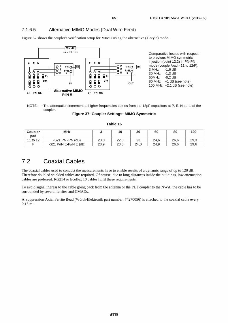
ETSI
ETSI TR 101 562-1 V1.3.1 (2012-02)65
7.1.6.5 Alternative MIMO Modes (Dual Wire Feed)
Figure 37 shows the coupler's verification setup for MIMO using the alternative (T-style) mode.
Comparative losses with respect to previous MIMO symmetric injection (point 12.2) in PN-PN mode (coupler/pad - 11 to 12/F): 3 MHz -1,6 dB 30 MHz -1,3 dB 60MHz -0,2 dB 80 MHz +1 dB (see note) 100 MHz +2,1 dB (see note)
NOTE: The attenuation increment at higher frequencies comes from the 18pF capacitors at P, E, N ports of the coupler.
Figure 37: Coupler Settings: MIMO Symmetric
Table 16
Coupler pad
MHz 3 10 30 60 80 100
11 to 12 -S21 PN -PN (dB) 23,0 22,8 23 24,6 26,6 29,3 F -S21 P//N E-P//N E (dB) 23,9 23,8 24,0 24,9 26,6 29,6
7.2 Coaxial Cables The coaxial cables used to conduct the measurements have to enable results of a dynamic range of up to 120 dB. Therefore doubled shielded cables are required. Of course, due to long distances inside the buildings, low attenuation cables are preferred. RG214 or Ecoflex 10 cables fulfil these requirements.
To avoid signal ingress to the cable going back from the antenna or the PLT coupler to the NWA, the cable has to be surrounded by several ferrites and CMADs.
A Suppression Axial Ferrite Bead (Würth-Elektronik part number: 74270056) is attached to the coaxial cable every 0,15 m.
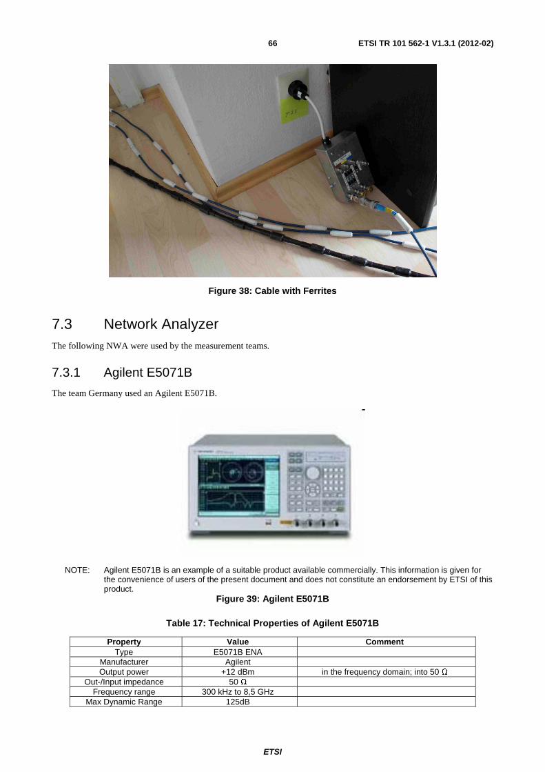
ETSI
ETSI TR 101 562-1 V1.3.1 (2012-02)66
Figure 38: Cable with Ferrites
7.3 Network Analyzer The following NWA were used by the measurement teams.
7.3.1 Agilent E5071B
The team Germany used an Agilent E5071B.
NOTE: Agilent E5071B is an example of a suitable product available commercially. This information is given for the convenience of users of the present document and does not constitute an endorsement by ETSI of this product.
Figure 39: Agilent E5071B
Table 17: Technical Properties of Agilent E5071B
Property Value Comment Type E5071B ENA
Manufacturer Agilent Output power +12 dBm in the frequency domain; into 50 Ω
Out-/Input impedance 50 Ω Frequency range 300 kHz to 8,5 GHz
Max Dynamic Range 125dB

ETSI
ETSI TR 101 562-1 V1.3.1 (2012-02)67
7.3.2 Agilent E5071C
The teams Belgium and France, Lannion used an Agilent E5071C ENA Network Analyzer.
NOTE: Agilent E5071C is an example of a suitable product available commercially. This information is given for the convenience of users of the present document and does not constitute an endorsement by ETSI of this product.
Figure 40: Agilent E5071C
Table 18: Technical Properties of Agilent E5071C
Property Value Comment Type E5071C ENA
Manufacturer Agilent Output power +10 dBm in the frequency domain; into 50 Ω
Out-/Input impedance 50 Ω Frequency range 9 kHz to 6,5 GHz
Max Dynamic Range 123 dB
7.3.3 Rohde & Schwarz ZVB4
The team in Spain used a Rohde & Schwarz ZVB4 Network Analyzer.
NOTE: Rohde & Schwarz ZVB4 is an example of a suitable product available commercially. This information is given for the convenience of users of the present document and does not constitute an endorsement by ETSI of this product.
Figure 41: Rohde & Schwarz ZVB4
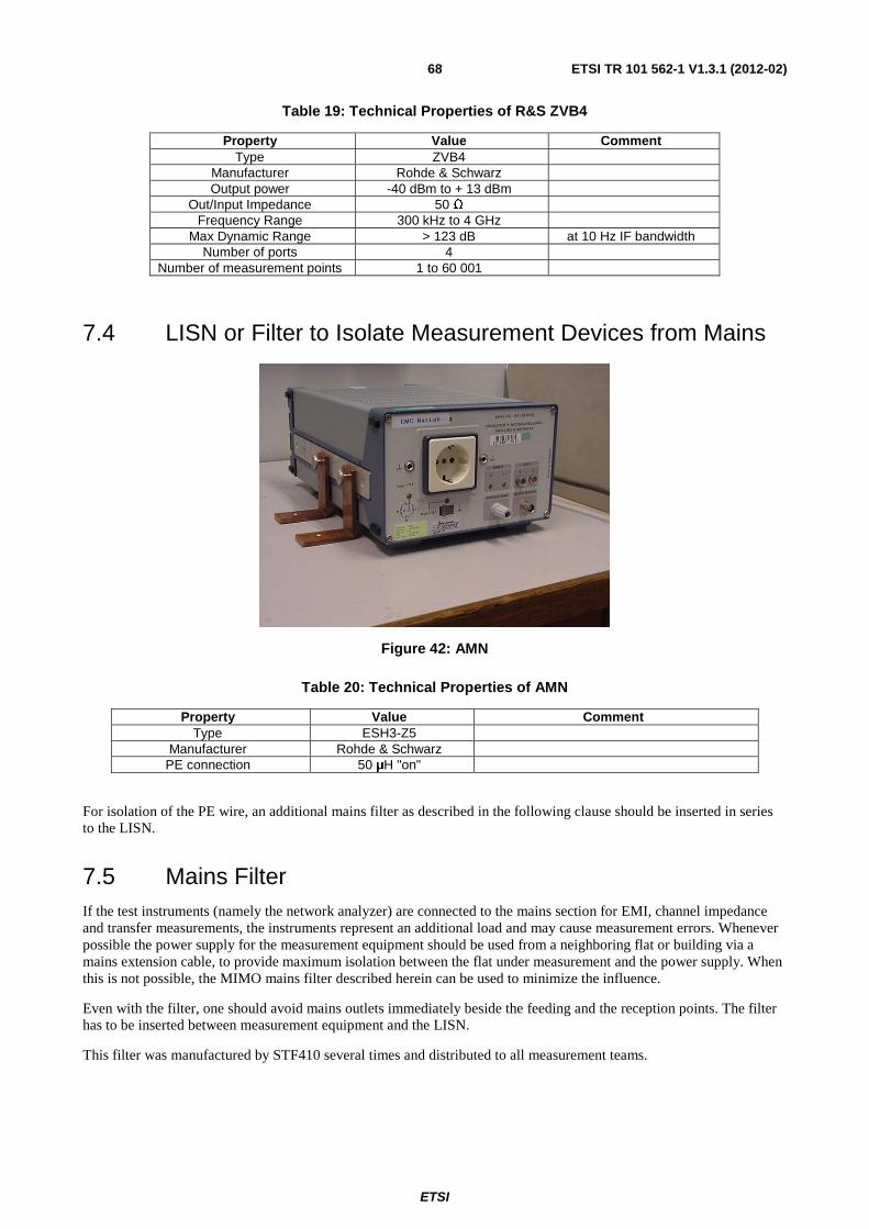
ETSI
ETSI TR 101 562-1 V1.3.1 (2012-02)68
Table 19: Technical Properties of R&S ZVB4
Property Value Comment Type ZVB4
Manufacturer Rohde & Schwarz Output power -40 dBm to + 13 dBm
Out/Input Impedance 50 Ω Frequency Range 300 kHz to 4 GHz
Max Dynamic Range > 123 dB at 10 Hz IF bandwidth Number of ports 4
Number of measurement points 1 to 60 001
7.4 LISN or Filter to Isolate Measurement Devices from Mains
Figure 42: AMN
Table 20: Technical Properties of AMN
Property Value Comment Type ESH3-Z5
Manufacturer Rohde & Schwarz PE connection 50 μH "on"
For isolation of the PE wire, an additional mains filter as described in the following clause should be inserted in series to the LISN.
7.5 Mains Filter If the test instruments (namely the network analyzer) are connected to the mains section for EMI, channel impedance and transfer measurements, the instruments represent an additional load and may cause measurement errors. Whenever possible the power supply for the measurement equipment should be used from a neighboring flat or building via a mains extension cable, to provide maximum isolation between the flat under measurement and the power supply. When this is not possible, the MIMO mains filter described herein can be used to minimize the influence.
Even with the filter, one should avoid mains outlets immediately beside the feeding and the reception points. The filter has to be inserted between measurement equipment and the LISN.
This filter was manufactured by STF410 several times and distributed to all measurement teams.

ETSI
ETSI TR 101 562-1 V1.3.1 (2012-02)69
7.5.1 Schematic Diagram
A mains filter also attenuating the PE wire is shown below.
NWAmains
CM choke
> 10 uH
P
N
PE
22 // 22 uH // 1,2 k
22 // 22 uH // 1,2 k
3 x 10 nF
max 6 A
P
NPE
820 k
820 k
Figure 43: Schematic of Mains Filter
7.5.2 Typical Impedances of Decoupling Components
7.5.2.1 R/L Combinations - Mains Side
Table 21: Impedance R, L Circuit on Mains Side of STF410 Mains Filter
MHz 1,59 3 10 30 60 80 100 Z 79 135 450 1 100 650 440 340 Ω φ 58 58 64 - 4 - 50 - 60 - 60 degree
7.5.2.2 Common Mode Choke - Instrument (NWA) Side (4 turns)
Table 22: Impedance of CM Choke in STF410 Mains Filter
MHz 1,59 3 10 30 60 80 100 Z 110 240 610 850 580 400 310 Ω φ 89 82 42 - 16 - 51 - 62 - 64 degree
7.5.3 Figures of Mains Filter
Figure 44: Mains Filter with Closed Lid

ETSI
ETSI TR 101 562-1 V1.3.1 (2012-02)70
Figure 45: Filter View Inside
7.6 Ground Plane To achieve a low impedance or high capacity connection to ground, a huge ground plane is necessary. Especially for reproducibility of the received CM signal; the ground plane is essential. The size of the ground plane is sufficiently large when human contact no longer influences measurement results.
Figure 46: Ground Plane with PLC Coupler Connected Tight

ETSI
ETSI TR 101 562-1 V1.3.1 (2012-02)71
Annex A: Bibliography
• Terms of Reference for Specialist Task Force STF 410 (TC PLT) on "Measurements to Verify Feasibility of MIMO PLT". Version: 1.1, 6 May 2010.
ETSI
ETSI TR 101 562-1 V1.3.1 (2012-02)72
History
Document history
V1.1.1 May 2011 Publication as TR 101 562 (Historical)
V1.2.1 August 2011 Publication
V1.3.1 February 2012 Publication