tr 126 912 - v4.0.0 - universal mobile telecommunications … · b.2 test procedure ... b.3.4 data...
TRANSCRIPT

ETSI TR 126 912 V4.0.0 (2001-03)Technical Report
Universal Mobile Telecommunications System (UMTS);QoS for Speech and Multimedia Codec;
Quantitative performance evaluation of H.324 Annex C over 3G(3GPP TR 26.912 version 4.0.0 Release 4)

1
ETSI
ETSI TR 126 912 V4.0.0 (2001-03)3GPP TR 26.912 version 4.0.0 Release 4
ReferenceRTR/TSGS-0426912Uv4
KeywordsUMTS
ETSI
650 Route des LuciolesF-06921 Sophia Antipolis Cedex - FRANCE
Tel.: +33 4 92 94 42 00 Fax: +33 4 93 65 47 16
Siret N° 348 623 562 00017 - NAF 742 CAssociation à but non lucratif enregistrée à laSous-Préfecture de Grasse (06) N° 7803/88
Important notice
Individual copies of the present document can be downloaded from:http://www.etsi.org
The present document may be made available in more than one electronic version or in print. In any case of existing orperceived difference in contents between such versions, the reference version is the Portable Document Format (PDF).
In case of dispute, the reference shall be the printing on ETSI printers of the PDF version kept on a specific network drivewithin ETSI Secretariat.
Users of the present document should be aware that the document may be subject to revision or change of status.Information on the current status of this and other ETSI documents is available at http://www.etsi.org/tb/status/
If you find errors in the present document, send your comment to:[email protected]
Copyright Notification
No part may be reproduced except as authorized by written permission.The copyright and the foregoing restriction extend to reproduction in all media.
© European Telecommunications Standards Institute 2001.
All rights reserved.

2
ETSI
ETSI TR 126 912 V4.0.0 (2001-03)3GPP TR 26.912 version 4.0.0 Release 4
Intellectual Property RightsIPRs essential or potentially essential to the present document may have been declared to ETSI. The informationpertaining to these essential IPRs, if any, is publicly available for ETSI members and non-members, and can be foundin ETSI SR 000 314: "Intellectual Property Rights (IPRs); Essential, or potentially Essential, IPRs notified to ETSI inrespect of ETSI standards", which is available from the ETSI Secretariat. Latest updates are available on the ETSI Webserver (http://www.etsi.org/ipr).
Pursuant to the ETSI IPR Policy, no investigation, including IPR searches, has been carried out by ETSI. No guaranteecan be given as to the existence of other IPRs not referenced in ETSI SR 000 314 (or the updates on the ETSI Webserver) which are, or may be, or may become, essential to the present document.
ForewordThis Technical Report (TR) has been produced by the ETSI 3rd Generation Partnership Project (3GPP).
The present document may refer to technical specifications or reports using their 3GPP identities, UMTS identities orGSM identities. These should be interpreted as being references to the corresponding ETSI deliverables.
The cross reference between GSM, UMTS, 3GPP and ETSI identities can be found under www.etsi.org/key .
ETSI
ETSI TR 126 912 V4.0.0 (2001-03)
3
3GPP TR 26.912 version 4.0.0 Release 4
Contents
Foreword............................................................................................................................................................ 5
1 Scope ....................................................................................................................................................... 6
2 References ............................................................................................................................................... 6
3 Definitions and abbreviations.................................................................................................................. 6 3.1 Definitions ..........................................................................................................................................................6 3.2 Abbreviations .....................................................................................................................................................7
4 3GPP Configuration of H.324 annex C................................................................................................... 8
5 Performance............................................................................................................................................. 9 5.1 Audio..................................................................................................................................................................9 5.1.1 Introduction...................................................................................................................................................9 5.1.2 Results...........................................................................................................................................................9 5.2 Video ................................................................................................................................................................11 5.2.1 Introduction.................................................................................................................................................11 5.2.2 Test environment ........................................................................................................................................11 5.2.3 Results.........................................................................................................................................................12 5.2.3.1 Subjective results ..................................................................................................................................12 5.2.3.2 Objective results....................................................................................................................................14
Annex A: Quality degradation as a function of the FER and RBER in presence of background noise ................................................................................................................. 17
A.1 Results in Car Noise: ............................................................................................................................. 17
A.2 Results in Street Noise: ......................................................................................................................... 18
A.3 Results in Office Noise.......................................................................................................................... 19
Annex B: Simulation test of a video multimedia codec...................................................................... 20
B.1 Introduction ........................................................................................................................................... 20
B.2 Test Procedure....................................................................................................................................... 21 B.2.1 Simulation Model .............................................................................................................................................21 B.2.2 Source materials ...............................................................................................................................................22 B.2.3 Source encoding ...............................................................................................................................................22 B.2.3.1 Speech.........................................................................................................................................................22 B.2.3.2 Video...........................................................................................................................................................23 B.2.4 Multiplexing .....................................................................................................................................................23 B.2.5 Bit error injection .............................................................................................................................................23 B.2.5.1 Error pattern files ........................................................................................................................................23 B.2.5.2 Error pattern segments to be used at the simulation....................................................................................24 B.2.5.3 Injection of bit errors ..................................................................................................................................25 B.2.6 De-multiplexing ..........................................................................................................................................25 B.2.7 Video decoding.................................................................................................................................................25 B.2.8 Constraints and regulations ..............................................................................................................................25 B.2.8.1 Delay...........................................................................................................................................................25 B.2.8.1.1 Video.....................................................................................................................................................26 B.2.9 Statistical data to be reported............................................................................................................................26 B.2.9.1 Video coding bitrate [%6,2f kbps] and MUX overhead [%6,2f kbps]........................................................26 B.2.9.2 Speech coding bitrate [%6,2f kbps] and frame length [%d ms]..................................................................26 B.2.9.3 Video initial delay [%6,1f ms] ....................................................................................................................26 B.2.9.4 PSNR related data .......................................................................................................................................26 B.2.9.4.1 Total average PSNR, i.e., PSNRtotal [%6.2f dB] ....................................................................................26 B.2.9.4.2 Average PSNR for representative run, i.e., PSNRk* [%6.2f dB] ...........................................................26 B.2.9.4.3 Average PSNR in error-free case, i.e., PSNRfree [%6.2f dB].................................................................27 B.2.9.4.4 Standard deviation of PSNR, i.e., Sigma [%6.2f dB]............................................................................27

ETSI
ETSI TR 126 912 V4.0.0 (2001-03)
4
3GPP TR 26.912 version 4.0.0 Release 4
B.2.9.5 Coding frame rate [%5.2f frames/sec] ........................................................................................................27 B.2.9.6 Average dropframe rate [%6.2f %].............................................................................................................27 B.2.9.7 Out of delay constraints rate [%6.2f %]......................................................................................................27 B.2.9.8 Definition of video stationary delay............................................................................................................27 B.2.9.9 Decoded video of representative run ..........................................................................................................28
B.3 Subjective quality evaluation ................................................................................................................ 28 B.3.1 Structure of test ................................................................................................................................................28 B.3.1.1 Program.......................................................................................................................................................28 B.3.1.2 Training session ..........................................................................................................................................28 B.3.1.3 Scoring session ...........................................................................................................................................28 B.3.1.4 Video sequence ...........................................................................................................................................28 B.3.1.5 Structure of program...................................................................................................................................29 B.3.2 Editing process .................................................................................................................................................29 B.3.2.1 Producing training session ..........................................................................................................................29 B.3.2.2 Randomization ............................................................................................................................................29 B.3.3 Assessment .......................................................................................................................................................29 B.3.3.1 Test subjects................................................................................................................................................29 B.3.3.2 Facilities and equipment for test .................................................................................................................30 B.3.3.3 Score sheet ..................................................................................................................................................30 B.3.4 Data processing ................................................................................................................................................30 B.3.4.1 MOS [%4.2f] ..............................................................................................................................................31 B.3.4.2 Standard deviation of OS, i.e., os [%4.2f]..................................................................................................31
B.4 Test results and observations................................................................................................................. 31 B.4.1 Test results........................................................................................................................................................31 B.4.2 Observations.....................................................................................................................................................31
B.5 List of video/speech codecs and multiplexers employed in the simulation........................................... 32
B.6 Test results............................................................................................................................................. 33
Annex C: Change history ..................................................................................................................... 38

ETSI
ETSI TR 126 912 V4.0.0 (2001-03)
5
3GPP TR 26.912 version 4.0.0 Release 4
Foreword This Technical Report has been produced by the 3rd Generation Partnership Project (3GPP).
The contents of the present document are subject to continuing work within the TSG and may change following formal TSG approval. Should the TSG modify the contents of the present document, it will be re-released by the TSG with an identifying change of release date and an increase in version number as follows:
Version x.y.z
where:
x the first digit:
1 presented to TSG for information;
2 presented to TSG for approval;
3 or greater indicates TSG approved document under change control.
y the second digit is incremented for all changes of substance, i.e. technical enhancements, corrections, updates, etc.
z the third digit is incremented when editorial only changes have been incorporated in the document.
ETSI
ETSI TR 126 912 V4.0.0 (2001-03)
6
3GPP TR 26.912 version 4.0.0 Release 4
1 Scope The present document is meant to function as guidance in the work of other 3GPP work groups or work items. Such work may include conclusion on how to achieve detailed Stage 1 service requirements or suggestion of a set of recommended RAB parameters giving satisfactory user-to-user quality for a circuit switched multimedia service using 3G-324M.
2 References The following documents contain provisions which, through reference in this text, constitute provisions of the present document.
• References are either specific (identified by date of publication, edition number, version number, etc.) or non-specific.
• For a specific reference, subsequent revisions do not apply.
• For a non-specific reference, the latest version applies. In the case of a reference to a 3GPP document (including a GSM document), a non-specific reference implicitly refers to the latest version of that document in the same Release as the present document.
[1] "Volume 3; Specifications of air-interface for 3G mobile system (Version 1.0-0.3)", IMT-2000 Study Committee, Air-Interface WG/SWG2, Nov. 18th, 1998.
[2] "Volume 8; Codec specification for use in a 3G mobile system (Version 0.5.2)", IMT-2000 Study Committee, Codec WG (ARIB), July 21st, 1998.
[3] International Standard ISO/IEC 14494-2: "Information technology - Generic coding of audio-visual object - Part 2: Visual, 1999".
[4] ITU-T Recommendation H.263: "Video coding for low bit rate communication".
[5] ITU-T Recommendation H.245: "Control protocol for multimedia communication".
[6] ITU-T Recommendation H.223: "Multiplexing protocol for low bitrate multimedia communication".
[7] ITU-T Recommendation H.324: "Terminal for low bit rate multimedia communication".
[8] 3GPP TR 21.905: "3G Vocabulary".
[9] 3GPP TR 26.975: "Performance characterization of the AMR speech codec Version 1.1.0. Release 1999".
3 Definitions and abbreviations
3.1 Definitions For the purposes of the present document, the following terms and definitions apply.
Codec: a single media coder/decoder, or a multimedia system specific coder & decoder system. For example, 3GPP AMR (speech codec), ITU-T H.263 [4] (video codec) or ITU-T H.32x (multimedia system with included media codecs) are understood to fulfil the definition of a codec.
3GPP TS 21.905 [8] provides the definitions not listed in this clause.

ETSI
ETSI TR 126 912 V4.0.0 (2001-03)
7
3GPP TR 26.912 version 4.0.0 Release 4
3.2 Abbreviations For the purposes of the present document, the following abbreviations apply:
3G Third Generation Mobile Network 5DQS 5 step Discrete Quality Scale AC/DC Alternate Current/Direct Current AL1-AL3 Adaptation Layer 1-3 AL-SDU Adaptation Layer – Service Data Unit AMR Adaptive Multi-Rate Speech Codec ARIB Association of Radio Industries and Businesses BER residual Bit Error Ratio BT 500-8 ITU-R Recommendation, "Methodology for the subjective assessment of the quality of television
pictures" CCSRL Control Channel Segmentation and Reassembly Layer CIF Common Image Format (352x288 pixel) CRC Cyclic Redundancy Code FEC Forward Error Correction FER Frame Error Ratio GSM Global System for Mobile-communications H.223 ITU-T Recommendation, "Multiplexing protocol for low bit rate multimedia communication" H.245 ITU-T Recommendation, "Control protocol for multimedia communication" H.324 ITU-T Recommendation, "Terminal l for low bit rate multimedia communication" IEC International Electrotechnical Commission IMT-2000 International Mobile Telecommunications - 2000 ISO International Organization for Standardization ITU-R International Telecommunication Union – Radiocommunications Standardisation Sector ITU-T International Telecommunication Union – Telecommunications Standardisation Sector I-VOP Intra Video Object Plane kbps Kilo bits per second (used in Annex B) LAPM Link Access Procedure for Modem LCD Liquid Crystal Panel MOS Mean Opinion Score MPEG Moving Picture Expert Group MUX-PDU MUltipleX – Protocol Data Unit PLMN Public Land Mobile Network PSNR Peak Signal to Noise Ratio P-VOP Predicted Video Object Plane QCIF Quarter Common Image Format (176x144 pixel) QoS Quality of Service SS Single Stimulus TM-5 Test Model 5 VLC Variable Length Code WCDMA Wideband Code Division Multiple Access

ETSI
ETSI TR 126 912 V4.0.0 (2001-03)
8
3GPP TR 26.912 version 4.0.0 Release 4
4 3GPP Configuration of H.324 annex C
Figure 1
Figure 1 shows the main building block of a 3G-324M terminal. The standards inside […] are not mandatory. The configuration actually used for each of the four performances evaluations (Audio, Video, Control and Data) will be described under each heading.
Video I/O Equipment
Video Codec
H.263, [MPEG-4,
Audio I/O Equipment
Speech Codec AMR, [G.723.1 …] Optional
Receive Path Delay
Multiplex/
Demultiplex
H.223,
H.223 Annex A, H.223 Annex B, [H.223 Annex C, H.223 Annex D]
User Data Applications
Data Protocols
[V.14, LAPM, …]
System Control
H.245
3GPP Network
CCSRL NSRP [LAPM/V.4
Scope of TS 26.111
Call Set-up
Scope of TS 26.112

ETSI
ETSI TR 126 912 V4.0.0 (2001-03)
9
3GPP TR 26.912 version 4.0.0 Release 4
5 Performance
5.1 Audio
5.1.1 Introduction
This clause provides a subset of the AMR Characterisation test results expressed as speech quality degradation (in ∆MOS or ∆DMOS) compared to the EFR speech codec in error free conditions, as a function of the FER (Frame Error Rate) and RBER( Residual Bit Error Rate as defined for GSM). It is believed that these results would also apply to H.324M channel with equivalent error conditions. Additional results are provided in Annex A for test conditions under background noise (Car noise, Street noise and Office noise). The original test results are included in the AMR characterisation report (3GPP TR 26.975 [9]). They relate to a channel condition GSM TU3 IFH (Typical Urban 3 km/h Ideal Frequency Hopping).
These results could be updated once the AMR 3G Characterisation tests are completed.
Quality performances of audio codecs in H.324M channels should be included in future versions of this document, as these results become available.
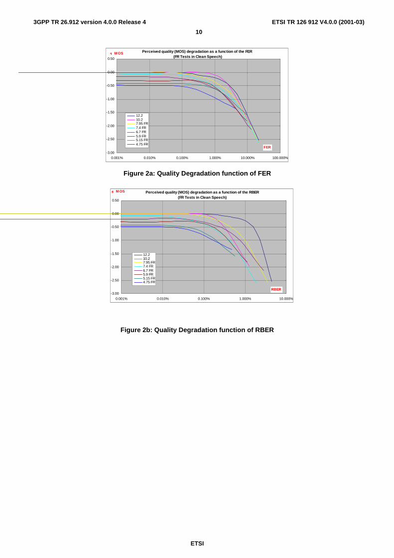
5.1.2 Results
The following diagrams present the speech quality degradation in clean speech (expressed in ∆MOS) for the different AMR codec modes, as a function of the FER and RBER, when compared to the EFR speech codec in error free condition. In all cases, the results represent the average scores obtained over all tests performed for each experiment as compiled in the GSM AMR Characterization report (3GPP TR 26.975 [9]). The EFR reference is taken from the score obtained by the EFR speech codec in error free in the same experiment.
The actual results were slightly altered to smoothen the curves’ shape.
Finally, it should also be noted that the diagrams function of the FER are actually affected by the Residual Bit Error Rate for each test condition, while the diagrams function of the RBER are also function of the FER present for each test condition. The two sets of diagrams cannot be considered totally independent. They are a reflection of the channel coding scheme selected for the GSM radio channels.
Finally, it should be pointed out that the FER and RBER estimates used to derive these diagrams are based on the limited number of error patterns used for the AMR characterization phase. These could be affected by some inaccuracies that could explain the difference in shapes between the different speech codec modes.
WARNING: These results are representative of the test conditions used for the GSM AMR characterization phase and may not be representative of the codec performances in other test conditions. When analyzing the original experiments, it was usually found that a difference in MOS lower than 0.2 was not statistically significant. For the following results, the confidence interval should also be increased by the uncertainty introduced in the estimation of the FER or RBER.
ETSI
ETSI TR 126 912 V4.0.0 (2001-03)
10
3GPP TR 26.912 version 4.0.0 Release 4
Perceived quality (MOS) degradation as a function of the FER (FR Tests in Clean Speech)
-3.00
-2.50
-2.00
-1.50
-1.00
-0.50
0.00
0.50
0.001% 0.010% 0.100% 1.000% 10.000% 100.000%
FER
' M OS
12.210.27.95 FR7.4 FR6.7 FR5.9 FR5.15 FR4.75 FR
Figure 2a: Quality Degradation function of FER
Perceived quality (MOS) degradation as a function of the RBER(FR Tests in Clean Speech)
-3.00
-2.50
-2.00
-1.50
-1.00
-0.50
0.00
0.50
0.001% 0.010% 0.100% 1.000% 10.000%
RBER
' M OS
12.210.27.95 FR7.4 FR6.7 FR5.9 FR5.15 FR4.75 FR
Figure 2b: Quality Degradation function of RBER

ETSI
ETSI TR 126 912 V4.0.0 (2001-03)
11
3GPP TR 26.912 version 4.0.0 Release 4
Comments on the previous results:
In clean speech, it appears that all AMR codec modes do not show any significant quality degradation when the Frame Erasure Rate is lower than 0.5%. In some instances, the range can even be extended to 1% FER without any quality degradation.
It is also interesting to note that at 1% FER degradation, the highest codec modes (12.2 and 10.2) are still equivalent to the second tier of codec modes (7.95 to 5.9) in error free. Similarly, the middle range codec modes (7.95 to 5.9) present the same quality at 1% FER than the lower rate codec modes (5.15 and 4.75) in error free conditions.
The results as a function of the RBER are quite similar with a different range of acceptable RBER. The AMR codec modes do not present any significant quality degradation when the RBER is below 0.1%.
Similar results under background noise conditions are provided in Annex A.
5.2 Video
5.2.1 Introduction
Qualitative evaluation of H.324 [7] Annex C over a simulated WCDMA Channel was carried out by ARIB (Association of Radio Industries and Businesses) IMT-2000 Study committee March 1999. The purpose of the test was to clarify the relationship between source/channel codec parameters and the channel bit-error conditions. A short description of the evaluation and a presentation of the results are included. The full test report is included in Annex B.
5.2.2 Test environment
The ARIB simulation was carried out as follows:
• source video sequences come into a video encoder;
• speech dummy data and video bitstreams are generated;
• the bitstreams are multiplexed into a single multiplexed bitstream in the form of MUX-PDU;
• bit errors are injected into the multiplexed bitstream (’1’ in error pattern file represents error);
• contaminated bitstream is de-multiplexed into speech and video bitstreams;
• de-multiplexed video bitstream is decoded by a video decoder;
• decoded video sequences are evaluated subjectively.
A layered overview of the test set up is shown in table 1.
Table 1
Layer Entity Instance Video Codec ISO MPEG-4 Simple Profile or ITU-T H.263 [4] Ver.2
Application Layer
Speech Codec Dummy data Mux Layer
Multiplexer De-multiplexer
H.223 [6]/M (mobile extension of ITU-T H.223 [6] multiplexing protocol)
Physical Layer
Simulated Wideband CDMA-channel
Error pattern files bitrate: 32 Kbit/s, 64 Kbit/s and 128 Kbit/s channel error condition BER: 1e-3, 1e-4 and 1e-6 velocity (model): 3km/h (Vehicular-A) and 120km/h (Vehicular-A)

ETSI
ETSI TR 126 912 V4.0.0 (2001-03)
12
3GPP TR 26.912 version 4.0.0 Release 4
5.2.3 Results
The results presented below should be used carefully. The subjective evaluation performed by ARIB provides good insight into the quality aspects of 3G-324M. However, attention should be paid to the following shortcomings: the test lacks a well known reference which makes it hard to asses the absolute picture quality furthermore the test methodology for low quality video is not very well developed which might be the reason for the high deviation in the results.
The objective results presented should also be used carefully. It is very hard to map objective measurements to subjective quality. However high objective quality generally does mean that the subjective quality is good and vice versa.
5.2.3.1 Subjective results
The following graphs are built from a subset of the data found in table in Clause B.6 of Annex B. Each codecs shown in the graphs had been tested for every error cases for each channel bit-rate. Since the evaluation lacked a known reference the MOS-values should be used very carefully. It is not the absolute value that is interesting but more the tendency.
For all three of the following graphs are the error channel described in the following way:
M64-10-3 where:
M means Mobile-to-Mobile Channel, it could also be an F for a Fix-to-Mobile channel
64 stands for the total bitrate on the channel i.e. 64 Kbit/s, 128 means 128 Kbit/s
10 is the interleaving depth in ms, other possibilities is 20 and 80 ms
3 bit-error-rate i.e. 10e-3, other tested bit-error-rates are 10e-4 and 10e-6
Results from two different sequences are shown: Overtime and Australia. Overtime is a typical "head and shoulder" scene while Australia is a multi-person conference scene with camera motion. The later is known, from the MPEG4 verification tests, to be difficult to code. The Overtime sequence has QCIF and the Australia CIF resolution. The coded video frame rate was not fixed in the test, however most of the experimenter used a frame rate around 10 Hz. Full information about the test to be found in Annex B.
MOS versus bit-error-rate, 64kps, Overtime
1
1,5
2
2,5
3
3,5
4
4,5
5
F64-10-6 M64-10-6 F64-20-4 M64-20-4 F64-10-3 M64-10-3
MPEG4 simple profile, H.223Level 1, 8kbps Audio
MPEG4 Simple profile, H.223Level 2, 8kbps Audio
H.263 Annex D, F, I, J, N, T,H.223 Level 2, 7.6 kbps Audio
MPEG4 simple profile, H.223Level 2, 7.6 kbps Audio
H.263 Annex D, F, N, R, H.223Level 2, 6.4 kbps Audio
MPEG4 simple profile, H223Level 3, 8.12 kbps Audio
Figure 3

ETSI
ETSI TR 126 912 V4.0.0 (2001-03)
13
3GPP TR 26.912 version 4.0.0 Release 4
Mos versus bit-error-rate, 64kps, Australia
1
1,5
2
2,5
3
3,5
4
4,5
5
F64-10-6 M64-10-6 F64-20-4 M64-20-4 F64-10-3 M64-10-3
H.263 Annex D, F, I, J, N, T,H.223 Level 2, 7.6 kbps Audio
MPEG4 simple profile, H.223Level 2, 7.6 kbps
MPEG4 simple profile, H.223Level 3wRS, 8 kbps
Figure 4
MOS versus bit-error-rate, 128 kps, Australia
1
1,5
2
2,5
3
3,5
4
4,5
5
F128-10.-6 M128-10-6 F128-20-4 M128-20-4 F120-10-3 M128-10-3
MPEG4 simple profile,H.223Level 2, 8 kbps Audio
MPEG4 simple profile,H.223Level 3wRS, 8 kbps Audio
Figure 5

ETSI
ETSI TR 126 912 V4.0.0 (2001-03)
14
3GPP TR 26.912 version 4.0.0 Release 4
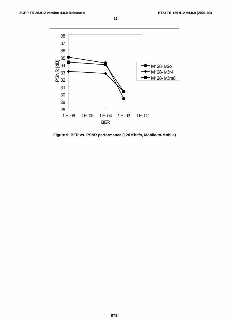
5.2.3.2 Objective results
As a comparison to the subjective results above, some objective data are presented for the same test cases. The tested sequence is Australia, two different bitrates are used (64 and 128 Kbit/s). Graphs for both Fix-to-Mobile and Mobile-to-Mobile are shown.
In these results, three different multiplex levels of H.223 [6] were used for each condition. The description of the error channel is the same as 5.3.2.1. Additional description for multiplex levels is as following:
Lv2o: Level 2 with optional header,
Lv3r4: Level 3 with FEC (convolutional code with a rate of 8/12),
Lv3rs8: Level 3 with FEC (Reed Solomon code with 8 symbol correction).
28
29
30
31
32
33
34
35
36
37
38
1.E-06 1.E-05 1.E-04 1.E-03 1.E-02BER
PSNR[dB]
F64-lv2oF64-lv3r4F64-lv3rs8
Figure 6: BER vs. PSNR performance (64 Kbit/s, Fix-to-Mobile)

ETSI
ETSI TR 126 912 V4.0.0 (2001-03)
15
3GPP TR 26.912 version 4.0.0 Release 4
��
��
��
��
��
��
��
��
�
�
��
��� � ��� �� ��� �� ��� �� ��� ��
���
�������
��
���� �������� ��������� ������
Figure 7: BER vs. PSNR performance (128 Kbit/s, Fix-to-Mobile)
��
��
��
��
��
��
��
��
�
�
��
��� � ��� �� ��� �� ��� �� ��� ��
���
�������
��
�� ������ ������� ������
Figure 8: BER vs. PSNR performance (64 Kbit/s, Mobile-to-Mobile)
ETSI
ETSI TR 126 912 V4.0.0 (2001-03)
16
3GPP TR 26.912 version 4.0.0 Release 4
��
��
��
��
��
��
��
��
�
�
��
��� � ��� �� ��� �� ��� �� ��� ��
���
�������
��
���� �������� ��������� ������
Figure 9: BER vs. PSNR performance (128 Kbit/s, Mobile-to-Mobile)

ETSI
ETSI TR 126 912 V4.0.0 (2001-03)
17
3GPP TR 26.912 version 4.0.0 Release 4
Annex A: Quality degradation as a function of the FER and RBER in presence of background noise The following diagrams are provided in complement to the AMR speech codec quality performance included in subclause 5.1. They show the quality degradation induced by the different speech codec modes as a function of the FER and RBER in presence of background noise (car noise in Figures A1a & A1b, street noise in Figures A2a & A2b and Office noise in Figures A3a & A3b).
The same comments on the origin of the test results as provided in subclause 5.1 also apply to the following diagrams.
A.1 Results in Car Noise:
Perceived quality (DMOS) degradation as a function of the FER (FR Tests in Car Noise)
-3.00
-2.50
-2.00
-1.50
-1.00
-0.50
0.00
0.50
0.001% 0.010% 0.100% 1.000% 10.000% 100.000%
FER
' DM OS
12.210.27.95 FR7.4 FR6.7 FR5.9 FR5.15 FR4.75 FR
Figure A.1a: Quality Degradation function of FER
Perceived quality (DMOS) degradation as a function of the RBER(FR Tests in Car Noise)
-3.00
-2.50
-2.00
-1.50
-1.00
-0.50
0.00
0.50
0.001% 0.010% 0.100% 1.000% 10.000%
RBER
' DM OS
12.210.27.95 FR7.4 FR6.7 FR5.9 FR5.15 FR4.75 FR
Figure A.1b: Quality Degradation function of RBER
In car noise, no significant degradation is observed when the FER stays below 1% and the difference in quality between the different codecs is slightly amplified compared to the results clean speech.
ETSI
ETSI TR 126 912 V4.0.0 (2001-03)
18
3GPP TR 26.912 version 4.0.0 Release 4
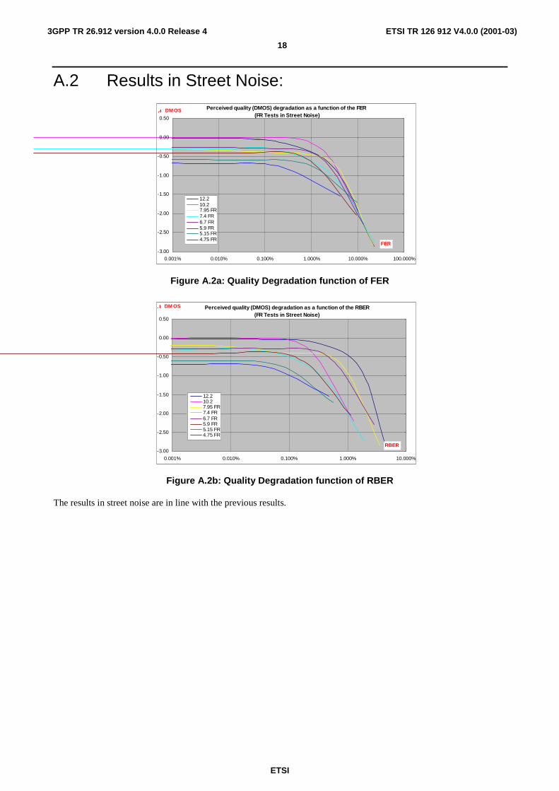
A.2 Results in Street Noise:
Perceived quality (DMOS) degradation as a function of the FER (FR Tests in Street Noise)
-3.00
-2.50
-2.00
-1.50
-1.00
-0.50
0.00
0.50
0.001% 0.010% 0.100% 1.000% 10.000% 100.000%
FER
' DM OS
12.210.27.95 FR7.4 FR6.7 FR5.9 FR5.15 FR4.75 FR
Figure A.2a: Quality Degradation function of FER
Perceived quality (DMOS) degradation as a function of the RBER(FR Tests in Street Noise)
-3.00
-2.50
-2.00
-1.50
-1.00
-0.50
0.00
0.50
0.001% 0.010% 0.100% 1.000% 10.000%
RBER
' DM OS
12.210.27.95 FR7.4 FR6.7 FR5.9 FR5.15 FR4.75 FR
Figure A.2b: Quality Degradation function of RBER
The results in street noise are in line with the previous results.

ETSI
ETSI TR 126 912 V4.0.0 (2001-03)
19
3GPP TR 26.912 version 4.0.0 Release 4
A.3 Results in Office Noise
Perceived quality (DMOS) degradation as a function of the FER (FR Tests in Office Noise)
-3.00
-2.50
-2.00
-1.50
-1.00
-0.50
0.00
0.50
0.001% 0.010% 0.100% 1.000% 10.000% 100.000%
FER
' DM OS
12.210.27.95 FR7.4 FR6.7 FR5.9 FR5.15 FR4.75 FR
Figure A.3a: Quality Degradation function of FER
Perceived quality (DMOS) degradation as a function of the RBER(FR Tests in Office Noise)
-3.00
-2.50
-2.00
-1.50
-1.00
-0.50
0.00
0.50
0.001% 0.010% 0.100% 1.000% 10.000%
RBER
' DM OS
12.210.27.95 FR7.4 FR6.7 FR5.9 FR5.15 FR4.75 FR
Figure A.3b: Quality Degradation function of RBER
Same comment for the results in Office Noise.

ETSI
ETSI TR 126 912 V4.0.0 (2001-03)
20
3GPP TR 26.912 version 4.0.0 Release 4
Annex B: Simulation test of a video multimedia codec
B.1 Introduction This Annex describes the simulation test of a real time, bi-directional video multimedia codec. It is a shorter version of the "Report of ARIB IMT-2000 Video Multimedia Codec Simulation Test" found in reference [2].
The purpose of the test is to clarify the relationship between source/channel codec parameters and the channel QoS (Quality of Service) parameters of available bearer channel set. While the source and channel codecs are specified with algorithms, tools, options and parameters, the channel QoS parameters include bitrate, BER (bit error rate) and delay. Resulting video associated with a certain combination of source/channel codec parameters and the channel QoS parameters is subjectively evaluated in terms of quality.
Twelve experimenters, that is, companies conducted the simulations. The experimenters individually and independently carry out the simulation using video codec and multiplexer prepared by each organization.
ETSI
ETSI TR 126 912 V4.0.0 (2001-03)
21
3GPP TR 26.912 version 4.0.0 Release 4
B.2 Test Procedure
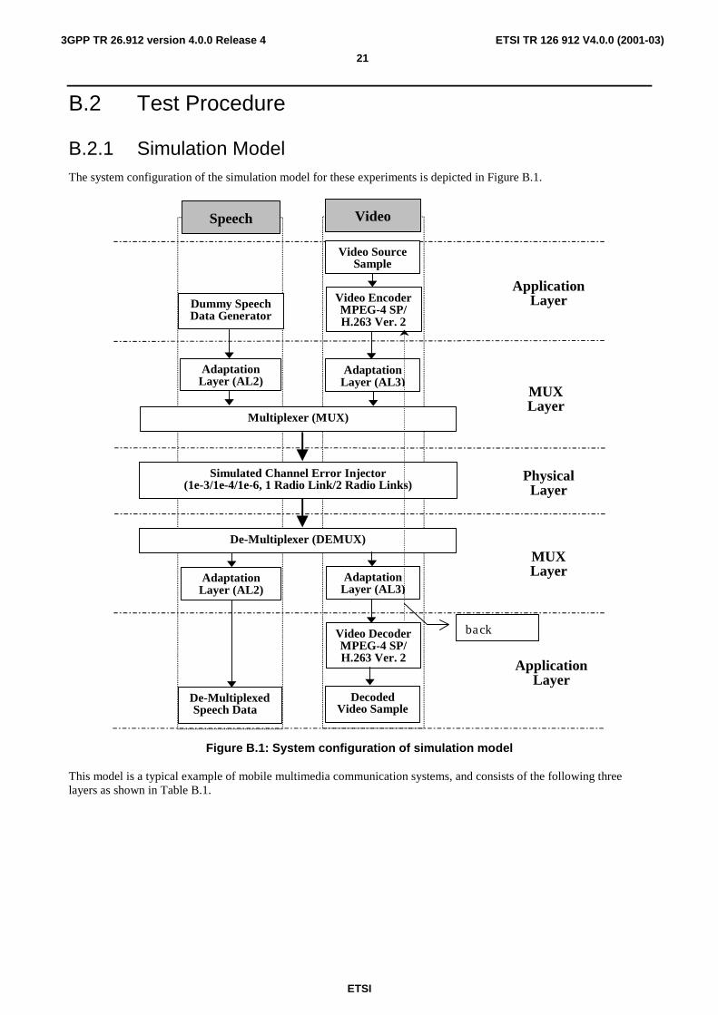
B.2.1 Simulation Model The system configuration of the simulation model for these experiments is depicted in Figure B.1.
Multiplexer (MUX)
Simulated Channel Error Injector(1e-3/1e-4/1e-6, 1 Radio Link/2 Radio Links)
De-Multiplexer (DEMUX)
AdaptationLayer (AL2)
Dummy SpeechData Generator
AdaptationLayer (AL2)
De-Multiplexed Speech Data
Speech
ApplicationLayer
ApplicationLayer
MUXLayer
MUXLayer
PhysicalLayer
Video EncoderMPEG-4 SP/H.263 Ver. 2
AdaptationLayer (AL3)
Video SourceSample
AdaptationLayer (AL3)
Video DecoderMPEG-4 SP/H.263 Ver. 2
DecodedVideo Sample
Video
back
Figure B.1: System configuration of simulation model
This model is a typical example of mobile multimedia communication systems, and consists of the following three layers as shown in Table B.1.

ETSI
ETSI TR 126 912 V4.0.0 (2001-03)
22
3GPP TR 26.912 version 4.0.0 Release 4
Table B.1: Layer structure of simulation model
Layer Entity Instance Video Codec ISO MPEG-4 Simple Profile or ITU-T H.263 [4] Ver.2
Application Layer
Speech Codec dummy data Mux Layer
Multiplexer De-multiplexer
H.223[6]/M (mobile extension of ITU-T H.223 [6] multiplexing protocol)
Physical Layer
IMT-2000 Air- Interface spec. (Vol. 3 Ver. 0.5)
error pattern files - bitrate: 32kbps, 64kbps and 128kbps - channel error condition BER: 1e-3, 1e-4 and 1e-6 - velocity (model): 3km/h (Vehicular-A) and 120km/h (Vehicular-A)
The simulation is generally carried out as follows:
• source video sequences come into a video encoder,
• speech dummy data and video bitstreams are generated,
• the bitstreams are multiplexed into a single multiplexed bitstream in the form of MUX-PDU,
• bit errors are injected into the multiplexed bitstream (’1’ in error pattern file represents error),
• contaminated bitstream is de-multiplexed into speech and video bitstreams,
• de-multiplexed video bitstream is decoded by a video decoder,
• decoded video sequences are evaluated subjectively.
B.2.2 Source materials
In the simulation two video sequences as shown in Table B.2 are used.
Table B.2: Video source material
Feature Name Provider Spatial
Resolution Temporal
Resolution Length [sec] Service
assumed Motion Scene Change
Overtime NTT DoCoMo
QCIF*1 30 fps 60 video telephony
low no
Australia France Telecom
QCIF*1
or CIF*2 25 fps 60
(72*3) video conference
middle twice
NOTE *1 QCIF: 176 (width) x 144 (height), 4:2:0 chroma format. *2 CIF : 352 (width) x 288 (height), 4:2:0 chroma format. *3 Australia is handled as 60 sec sequence of 30 fps, though it’s originally 72 sec of 25 fps.
B.2.3 Source encoding Clause B.5 shows the list of video/speech codecs and multiplexers employed by experimenters for the simulation.
B.2.3.1 Speech
Dummy random data, which are generated by each experimenter, are used to simulate encoded speech bitstream. The assumed coding bitrate and frame lengths of dummy speech data are left at the experimenter’s discretion.

ETSI
ETSI TR 126 912 V4.0.0 (2001-03)
23
3GPP TR 26.912 version 4.0.0 Release 4
B.2.3.2 Video
Either ISO MPEG-4 Video Simple Profile or ITU-TRecommendation H.263 [4] Ver. 2 is employed as a video codec. There are some optional tools and parameters that can be set at the encoder for both specifications. Each experimenter taking speech coding bitrate and MUX overhead into account shall decide the bitrate allocated to video coding. A typical example is 8 kbps speech, 48 kbps video and 8 kbps MUX overhead, which results in 64 kbps in total.
Some coding parameters are fixed to facilitate the simulation and demonstration by reducing the number of simulation conditions:
• coding bitrate; 32 kbps and 64 kbps for Overtime, 64 kbps and 128 kbps for Australia,
• spatial resolution of test sequence; QCIF for Overtime, CIF for Australia 128 kbps coding, and QCIF or CIF for Australia 64 kbps coding,
• initial frame alignment; the 1st frame of test sequence shall be encoded as 1st intra-coded frame. It is noted that coding frame rate is left at the experimenter’s discretion.
B.2.4 Multiplexing ITU-T Recommendation H.223 [6]/M (mobile extension) with its annexes namely Annex A, Annex B, Annex C and Annex D is used as a multiplexing protocol. As for the adaptation layer, AL3 is used for video and AL2 for speech. The use of the optional tools like control field, re-transmission and the optional header field in the Annex B is up to the experimenters.
B.2.5 Bit error injection
B.2.5.1 Error pattern files
The bit error patterns are generated based on Vol. 3 Ver. 0.5 (ARIB IMT-2000 A/IF specification) [1] issued on Nov. 18th, 1998 [Ed. Note, This is a WCDMA channel]. The frame structure of the bit error file is shown in Figure B.2, which is identical to the air channel frame assumed. The frame is in 10-msec unit, and each frame is composed of CRC (16 bits) and INFO bits (10-msec worth of user bitrate). The multiplexed or encoded bitstream is assumed to be transmitted as INFO bits on a frame basis. The 16-bit CRC is originally designed to detect errors in the corresponding INFO bits at the physical layer. It can, however, be exploited at the application layer (e.g., source codec and MUX). In this simulation, the CRC is not used, hence, the 16-bit CRC should be merely discarded. It shall be noted that the CRC may be able to improve the performance of use applications. This is left for further study.
CRC16
INFONch_info
CRC16
INFONch_info
CRC16
INFONch_info
)U DPH� XQL W � � ��PV�
givenBit Error Pattern
Ncodec_infoNcodec_info
INFONcodec_info
INFONcodec_info
Bit Errors added to Encoded bit-stream.
Figure B.2: Frame structure of bit error pattern file
The bit error patterns in binary format are then provided as summarized in Table B.3. Among them, the error pattern files of Vehicular-A, 120km/h propagation model are used for the test of mobile-to-land mode. The mobile-to-mobile (M2M) error pattern files weren’t provided. M2M files was thus generated by XORing (exclusive OR) forward link and reverse link appropriately. Unfortunately reverse link files are available only for 32kbps, 1e-3 case. Therefore, error pattern of M2M mode are synthesized by XORing two forward link files that are the same in bitrate, BER and interleave length but only differ in propagation model. The two propagation models used are 3km/h and 120km/h of vehicular-A.

ETSI
ETSI TR 126 912 V4.0.0 (2001-03)
24
3GPP TR 26.912 version 4.0.0 Release 4
Table B.3: Bit error pattern files
Radio Channel Type Ref.
File Name FL/ RL
Bitrate [kbps]
Interleave Size
[msec]
BER File
Length [sec]
Speed [km/h]
Propagation model
Eb/Io [dB] SG4/VMG
File#
F32-10-3-V3a FL 32 10 1e-3 300 3 Veh-A 2.57 SG4-7 F32-10-3-V120a 120 Veh-A 3.93 SG4-10
F32-20-4-V3 20 1e-4 300 3 Veh-A 2.59 VMG-1 F32-20-4-V120 120 Veh-A 3.90 VMG-2 F32-10-6-V3 10 1e-6 5000 3 Veh-A 3.96 SG4-41
F32-10-6-V120a 120 Veh-A 5.63 SG4-43 F32-80-6-V3 80 3 Veh-A 2.42 SG4-45
F32-80-6-V120a 120 Veh-A 3.66 SG4-47 F64-10-3-V3a 64 10 1e-3 300 3 Veh-A 2.18 SG4-13
F64-10-3-V120a 120 Veh-A 3.39 SG4-16 F64-20-4-V3 20 1e-4 300 3 Veh-A 2.16 VMG-3
F64-20-4-V120 120 Veh-A 3.47 VMG-4 F64-10-6-V3 10 1e-6 5000 3 Veh-A 3.63 SG4-25
F64-10-6-V120a 120 Veh-A 5.06 SG4-27 F64-80-6-V3 80 3200 3 Veh-A 2.00 SG4-29
F64-80-6-V120a 120 Veh-A 3.28 SG4-31
F128-10-3-V3 128 10 1e-3 300 3 Veh-A 0.93 VMG-5 F128-10-3-V120 120 Veh-A 2.21 VMG-6 F128-20-4-V3 20 1e-4 300 3 Veh-A VMG-7
F128-20-4-V120 120 Veh-A VMG-8 F128-10-6-V3 10 1e-6 3000 3 Veh-A 2.24 SG4-49
F128-10-6-V120a
120 Veh-A 3.91 SG4-51
F128-80-6-V3 80 1600 3 Veh-A 0.99 SG4-53 F128-80-6-
V120a 120 Veh-A 1.98 SG4-55
R32-10-3-V3 RL 32 10 1e-3 300 3 Veh-A 2.48 VMG-9 R32-10-3-V120 120 Veh-A 3.86 VMG-10
B.2.5.2 Error pattern segments to be used at the simulation
Multiple-run simulation leads to more reliable results. Therefore it was decided to use 20 runs per error pattern file, i.e., parent file. It should be noted that the successive processes namely de-multiplexing and source decoding are repeated 20 times accordingly. An extracted file is denoted "error pattern segment", so 20 error pattern segments (denoted as seg#0 - seg#19) are extracted from each error pattern file. Note that duration of error pattern segments must be identical to that of test sequence, hence, 60 seconds for both Overtime and Australia. These error pattern segments, which shall represent respective test condition, are extracted as follows.
• In case of 1e-3 and 1e-4 BERs, 20 error pattern segments, initial frame of which are equally distributed over 5-min error pattern file, are extracted. Each segment is composed of successive frames in an error pattern file. The initial frame number of seg#0 is zero, and those of the following segments fall with fixed interval; 1200 frames (12 seconds).
• In case of 1e-6 BER, an intermediate file of 20 segments worth length, whose actual BER is as close to 1e-6 as possible, is sought over an error pattern file. Then 20 segments are extracted from the intermediate file. The initial frame of seg#0 collocates that of the intermediate file. As to the rest, they are extracted in the way that seg#N (where N=1,...,19) immediately follows seg#N-1.
• Firstly, 20 error pattern segments are extracted for each propagation model. The M2M error pattern segments are generated by XORing these extracted segments. In this process segment number must be matched, that is, XORing seg#N (where N=0,...,19) of 3km/h model and seg#N of 120km/h model yields seg#N of M2M model.

ETSI
ETSI TR 126 912 V4.0.0 (2001-03)
25
3GPP TR 26.912 version 4.0.0 Release 4
B.2.5.3 Injection of bit errors
To simulate the noisy channel, those bit errors are injected into multiplexed bitstream. This process is done by XOR in bit-wise fashion. But the initial error free period is tailored to protect the important part of the bitstream, since errors on such portion probably cause fatal damages in the source decoding process. Therefore the initial 100 bytes from the beginning of the multiplexed bitstream, which is denoted error-free period, are enforced to be error-free. So bit errors are injected immediately after the error-free period in multiplexed bitstream (Precisely the 1st bit of error patterns shall collocate 801st bit (both counting from one) of the multiplexed bitstream). If multiplexed bitstream is longer than error pattern segment plus 100 bytes, no error is applied to the tail part of the bitstream exceeding the length of error pattern segment plus 100 bytes. ITU-T Recommendation H.245 [5] Version 5 is designed to perform a capability exchange prior to the transmission of data streams. With this technique, the initial error-free period can be realized by means of re-transmission.
B.2.6 De-multiplexing
The multiplexed bitstream is de-multiplexed at the receiver side. This process comes out with de-multiplexed speech bitstream and de-multiplexed video bitstream in the form of AL-SDU. Errors may be detected in some units of those bitstream with error detection capability of the multiplexing protocol. In that case it is up to the experimenter to decide whether erroneous AL-SDUs are delivered to the AL user, i.e., video decoder, or simply discarded. When erroneous AL-SDUs are delivered to respective AL user, it is possible that the AL user is notified of the presence of errors in delivered AL-SDU by the de-multiplexer
B.2.7 Video decoding The de-multiplexed video bitstream is decoded. The video decoder has less freedom in selecting optional tools compared to the encoder, but has more freedom of operation outside of the standard, e.g., error detection, error recovery, error concealment and post processing. The use of these non-normative tools and proprietary schemes is up to the experimenters. To align the spatial resolution at subjective evaluation test, "Australia" sequence encoded at QCIF size shall be up-sampled to CIF size. Then "Overtime" and "Australia" sequences are displayed at the size of QCIF and CIF, respectively. For QCIF-to-CIF conversion, the up-sampling filter [FILTER] employed at MPEG-4 experiments is used.
B.2.8 Constraints and regulations
B.2.8.1 Delay
In considering adequate combination of bearer radio channel and codec parameters, both channel and codec affect the delay. Therefore the delay constraints shall be investigated in both aspects simultaneously. Table B.4 summarizes the delay constraints to meet. It shall be noted that delay due to multiplexing/de-multiplexing heavily depends on the system configuration. Given that processing power of MUX related components are high enough, the delay at MUX layer can be absorbed into the video delay. So in the simulation, it is assumed that the delay at MUX layer is negligible, i.e., zero.
Table B.4: Delay constraints
Total allowable
delay
Allowable delay for air interface,
network
Allowable delay for codec and MUX
Associated BER
10x2*,50 330 1e-3, 1e-6 20x2*,50 310 1e-4
400 ms
80x2*,50 190 1e-6 NOTE: * Multiplying by 2 means two links for mobile-to-mobile.
ETSI
ETSI TR 126 912 V4.0.0 (2001-03)
26
3GPP TR 26.912 version 4.0.0 Release 4
B.2.8.1.1 Video
The video delay is classified into two; initial delay and stationary delay. The former is defined with coding bits consumed at the 1st intra-coded frame, and is quantified by the coding bits divided by video coding bitrate. In the subjective test, when the initial delay exceeds 600 ms, mid-gray background is displayed with duration identical to the initial delay before presenting decoded video sequence. The latter is the one calculated based on the delay model described in B.2.9.8. It is, however, found difficult and impractical to always keep the stationary delay below the prescribed values shown in Table B.4 considering a variety of natures of input video sequences. While the experimenters are yet strongly encouraged to obey the above constraints, they are exceptionally allowed not to do. It is noted that such violation is admitted only when it is essential and rather practical than obeying the constraints.
B.2.9 Statistical data to be reported The following items shall be reported on a test condition basis, i.e., one per error pattern file.
B.2.9.1 Video coding bitrate [%6,2f kbps] and MUX overhead [%6,2f kbps]
B.2.9.2 Speech coding bitrate [%6,2f kbps] and frame length [%d ms]
B.2.9.3 Video initial delay [%6,1f ms]
The video initial delay is calculated as coding bits for initial intra-coded frame divided by video coding bitrate
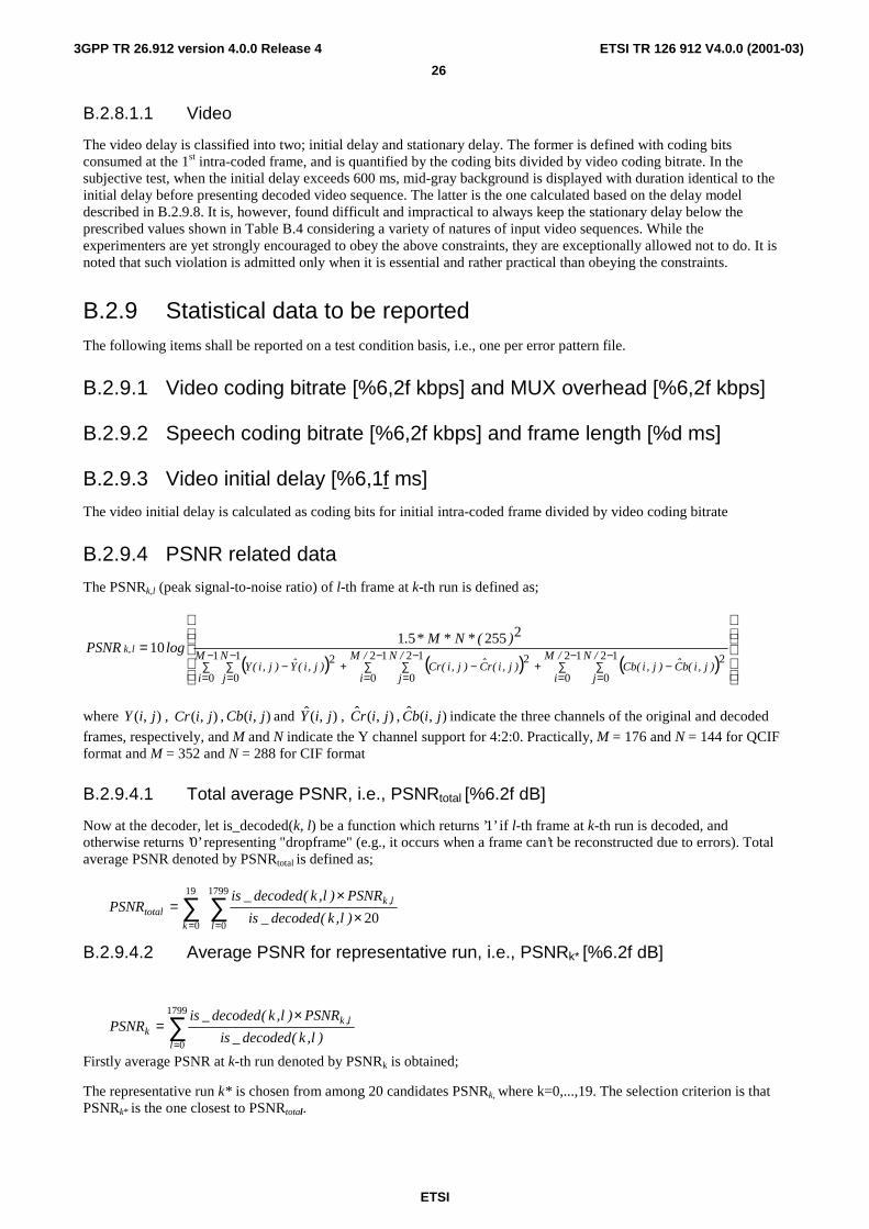
B.2.9.4 PSNR related data
The PSNRk,l (peak signal-to-noise ratio) of l-th frame at k-th run is defined as;
( ) ( ) ( )
=∑−
=∑−
=∑
−
=∑
−
=−+∑
−
=∑
−
=−+−
1
0
1
0
12
0
12
0
212
0
12
0
22
22555110
M
i
N
j
/M
i
/N
j)j,i(bC)j,i(Cb
/M
i
/N
j)j,i(rC)j,i(Cr)j,i(Y)j,i(Y
)(*N*M*.logPSNR lk,
where ),( jiY , ),( jiCr , ),( jiCb and ),(ˆ jiY , ),(ˆ jirC , ),(ˆ jibC indicate the three channels of the original and decoded
frames, respectively, and M and N indicate the Y channel support for 4:2:0. Practically, M = 176 and N = 144 for QCIF format and M = 352 and N = 288 for CIF format
B.2.9.4.1 Total average PSNR, i.e., PSNRtotal [%6.2f dB]
Now at the decoder, let is_decoded(k, l) be a function which returns ’1’ if l-th frame at k-th run is decoded, and otherwise returns ’0’ representing "dropframe" (e.g., it occurs when a frame can’t be reconstructed due to errors). Total average PSNR denoted by PSNRtotal is defined as;
B.2.9.4.2 Average PSNR for representative run, i.e., PSNRk* [%6.2f dB]
Firstly average PSNR at k-th run denoted by PSNRk is obtained;
The representative run k* is chosen from among 20 candidates PSNRk, where k=0,...,19. The selection criterion is that PSNRk* is the one closest to PSNRtotal.
∑∑== ×
×=
1799
0
19
020
l
l,k
ktotal )l,k(decoded_is
PSNR)l,k(decoded_isPSNR
∑=
×=
1799
0l
l,kk )l,k(decoded_is
PSNR)l,k(decoded_isPSNR

ETSI
ETSI TR 126 912 V4.0.0 (2001-03)
27
3GPP TR 26.912 version 4.0.0 Release 4
B.2.9.4.3 Average PSNR in error-free case, i.e., PSNRfree [%6.2f dB]
The average PSNR in error-free case represented by PSNRfree is obtained in the similar way above. To precisely define the term, it is the average PSNR calculated when decoding error-free video bitstream.
B.2.9.4.4 Standard deviation of PSNR, i.e., Sigma [%6.2f dB]
The Sigma is represented as;
B.2.9.5 Coding frame rate [%5.2f frames/sec]
Like is_decoded(k, l), let is_encoded( l) denote a function which returns ’1’ if l-th frame is encoded at the encoder, and
otherwise returns ’0’. The coding frame rate is expressed as;
B.2.9.6 Average dropframe rate [%6.2f %]
The average dropframe rate is defined as;
B.2.9.7 Out of delay constraints rate [%6.2f %]
Let is_outofdelay(l) represent a function which returns ’1’ if the delay constraints can not be observed at l-th frame, and otherwise returns ’0’. Note is_outofdelay(l) is meaningful only when the l-th frame is encoded, i.e., is_encoded(l)=1.
Now the out of delay constraints rate is defined as;
B.2.9.8 Definition of video stationary delay
The video stationary delay, Dn, for the n-th (n = 1, 2, ...) coded frame in the transmitted sequence is defined as follows (the delay model defined has no relation between the buffering model described in the MPEG-4 [3] or H.263 [4] specification):
Dn = Tn - On,
where On denotes the time when the n-th coded frame occurs, and Tn denotes the time when the last bit of the coded information related to the n-th coded frame is transmitted from the transmitting side.
For example, when the video information is coded at the fixed bitrate of R bits/s, Dn is defined as follows:
n
n
i
i
n OR
B
OD −+=∑
=11 ,
∑=
−=
19
0
2
19k
ktotal )PSNRPSNR(Sigma
∑=
=1799
060
l
)l(encoded_israte_frame_coding
∑∑==
−×=
1799
0
19
0
100lk
)l(encoded_is
)l,k(decoded_is)l(encoded_israte_dropframe_average
∑=
×=1799
0
100l
)l(encoded_is
)l(outofdelay_is&)l(encoded_israte_sintconstra_delay_of_out

ETSI
ETSI TR 126 912 V4.0.0 (2001-03)
28
3GPP TR 26.912 version 4.0.0 Release 4
where Bn is the number of transmitted bits for the n-th coded frame.
The encoder shall encode a frame which occurred before the transmission of the information related to the previous coded frame is finished. This condition is described as:
On ≤ Tn-1 .
In the fixed bitrate case, this equation is rewritten as:
R
B
OO
n
ii
n
∑−
=+≤
1
11 .
B.2.9.9 Decoded video of representative run
The decoded video sequence shall ideally be displayed as it is demonstrated using actual real time codec. It is, however, found difficult for all experimenters to tailor such real time codec. Therefore, experimenters shall submit the decoded video of representative run. For simplicity sake, the decoded video is displayed according to the time stamp of encoded frames, assuming the time stamp is not so much deviated from presentation time at decoder.
B.3 Subjective quality evaluation The video subjective quality evaluation test is performed based on so-called SS-5DQS, that is, single stimulus (SS) method with a 5-point discrete quality scale (5DQS) referred to as ITU-R BT 500-8. However, the test is not designed to be fully compliant to SS-5DQS, but is rather simplified. There are five grades; excellent, good, fair, poor and bad. It shall be noted that the grading is made under the assumption that those video sequences, hence, associated video codecs are employed for prospective IMT-2000 mobile terminals. In this context, LCD monitors are employed as display since the mobile terminal for video related services will most likely be equipped with LCD monitors.
B.3.1 Structure of test
B.3.1.1 Program
The subjective test is composed of several programs. A program is designed to be 20-40 minute long taking account of concentration duration of test subjects. A program is comprised of a training session followed by a scoring session. "Overtime" and "Australia" are handled separately in this level.
B.3.1.2 Training session
In order for test subjects to establish their own criteria on video subjective quality, a training session is tailored prior to actual evaluation. A training session consists of five video sequences, and there are two training sessions; one for "Overtime" and another for "Australia". These two are commonly used to every program in respective category. No score is put to sequences in a training session. A training session begins with 5-second indication notifying the beginning of the session. 5-second break is inserted between video sequences.
B.3.1.3 Scoring session
A scoring session is composed of multiple sequences, all of which are to be subjectively assessed. 10-second break is inserted between successive sequences. Test subject should mark a grade to a sequence during break which immediately follow the said sequence.
B.3.1.4 Video sequence
A video sequence, or sequence, represents a series of decoded images which is of 1-minute long.

ETSI
ETSI TR 126 912 V4.0.0 (2001-03)
29
3GPP TR 26.912 version 4.0.0 Release 4
B.3.1.5 Structure of program
A structure of a program is given in Table B.5.
Table B.5: Structure of program
Session Components Contents Duration [s] Time elapsed Indication training session 5 training #1 video sequence 60
Break gray image 5 training #2 video sequence 60
Break gray image 5 ���
Training
training #5 video sequence 60 5’25" indication scoring session 10
evaluation #1 video sequence 60 score and break gray image 10
evaluation #2 video sequence 60 score and break gray image 10
��� evaluation #23* video sequence 60
Scoring
score gray image 10 32’25" NOTE The total number of sequences in a scoring session ranges from 21 to 23
depending on program.
B.3.2 Editing process The decoded video sequences submitted by experimenters are to be edited, i.e., re-organized complying with a simplified SS-5DQS method.
B.3.2.1 Producing training session
Five sequences, each for "Overtime" and "Australia", are to be picked up. Two extremes, one in the best quality class and one in the worst quality class shall be included in a training session. The other three are to be picked up covering various classes in video quality.
B.3.2.2 Randomization
"Overtime" and "Australia" sequences are dealt with separately, and those related programs are denoted like "O1" which represents the first program of "Overtime". Firstly the number of programs are determined taking account of the total number of sequences. Since there are 91 and 64 sequences for "Overtime" and "Australia", respectively, 4 programs for "Overtime" and 3 programs for "Australia" are generated. Secondly sequential number is put to sequences properly. Then video sequences are classified into those programs using random numbers.
B.3.3 Assessment
B.3.3.1 Test subjects
According to an ITU-R recommendation, reliable MOS data can be obtained with 10 expert test subjects or with 20 non-expert test subjects or more. In this test, 15 (12 experts, 1 semi-expert and 2 non-experts)and 14 (11 experts, 2 semi-experts and 1 non-expert) test subjects are employed for evaluation of Overtime and Australia sequences, respectively.

ETSI
ETSI TR 126 912 V4.0.0 (2001-03)
30
3GPP TR 26.912 version 4.0.0 Release 4
Table B.6: Time schedule of test
Time Test Subject Group A Test Subject Group B Test Administrators
09:20 – 10:10 Equipment Set-up
10:10 – 10:30 Explanation of the Test Preparation for O1
10:33 – 11:06 Evaluation (Program O1) Break
11:06 – 11:12 Break Preparation for A1
11:12 – 11:44 Evaluation (Program A1)
11:44 – 11:52 Lunch Break Preparation for O2 11:52 – 12:25 Evaluation (Program O2)
12:25 – 13:00 Lunch Break Preparation for A2������
13:00 – 13:33 Evaluation (Program A2)
13:33 – 13:40 Break Preparation for O3
13:40 – 14:13 Evaluation (Program O3)
14:13 – 14:20 Break Preparation for A3
14:20 – 14:53 Evaluation (Program A3)
14:53 – 15:00 Dismissal (after above) Preparation for O4
15:00 – 15:33 Evaluation (Program O4)
Dismissal (after above)
15:33 – 16:00 Equipment Take-down
B.3.3.2 Facilities and equipment for test
As many as 15 test subjects shall conduct the evaluation at the same time in the subjective test. From among several possible solutions the following equipment is deployed for the test. One set capable of handing four LCD monitors (including one parent PC) is composed of; 1) one high-performance PC, 2) one Dsub15-to-BNC video interface (Umezawa, ITF-400), 3) one 1BNC-to-3BNC video splitter (Umezawa, UM-4700A), 4) three BNC-to-Dsub15 conversion boxes (Umezawa, ADA-400) and 5) three LCD monitors. Given that two test subjects share an LCD, two sets of above are necessary and can synchronously display video on up to 8 LCDs (including two parent PCs).
B.3.3.3 Score sheet
Score sheet is made on a program basis, and given to test subjects prior to each program. The format of score sheet is depicted in Figure B.3, which exemplifies the case of "A1-01" marked "Good" and "A1-02" marked "Fair".
No. Excellent Good Fair Poor Bad
A1-01 A1-02
Figure B.3: Format of score sheet (example of "A1-01" marked "Good" and "A1-02" marked "Fair"
The following instruction is described on a score sheet; "Test subject shall subjectively judge how well quality of video sequence meets the quality test subject expects for IMT-2000 real time video communication services assumed. The best and worst quality sequences don’t necessarily correspond to the grades excellent and bad, respectively."
B.3.4 Data processing
MOS (mean opinion score) and its standard deviation denoted by os are calculated and to be reported as subjective test results.

ETSI
ETSI TR 126 912 V4.0.0 (2001-03)
31
3GPP TR 26.912 version 4.0.0 Release 4
B.3.4.1 MOS [%4.2f]
Let M and OS[i] denote the number of test subjects and the opinion score of i-th test subject. Note that OS[i] is associated with integers as below and so converted.
Excellent: 5 / Good: 4 / Fair: 3 / Poor: 2 / Bad: 1
Now the MOS is calculated as;
B.3.4.2 Standard deviation of OS, i.e., os [%4.2f]
The standard deviation of OS (opinion score) is expressed as;
B.4 Test results and observations
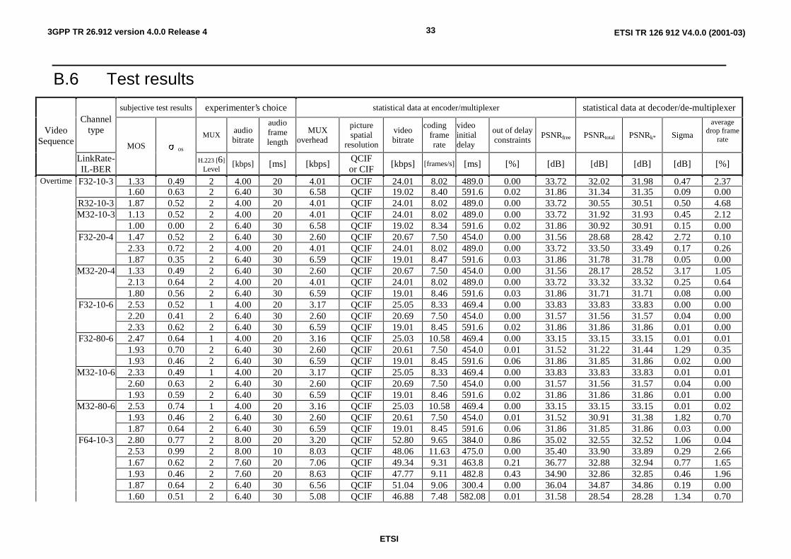
B.4.1 Test results The test results including both opinion scores and statistical data are shown in the table of in clause B.6. Both the subjective test results and statistical data obtained through the simulation test are tabulated there in terms of channel type.
B.4.2 Observations The characteristics of the residual errors on the simulated channels are considerably different from that of the ARIB IMT-2000 first video multimedia codec simulation test conducted in May-June 1998. The error density in the residual error burst is significantly lower this time probably due to the use of Turbo Codes [OBSERVE]. The effects of the used error correcting code, the residual error characteristic and its influence on the multimedia codec system have to be further investigated.
∑=
=M
iM
]i[OSMOS
1
∑= −
−=
M
iM
)MOS]i[OS(
1
2
os1
σ
ETSI
ETSI TR 126 912 V4.0.0 (2001-03)323GPP TR 26.912 version 4.0.0 Release 4
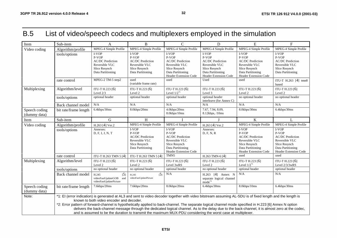
B.5 List of video/speech codecs and multiplexers employed in the simulation Item Sub-item A B C D E F
Algorithm/profile MPEG-4 Simple Profile MPEG-4 Simple Profile MPEG-4 Simple Profile MPEG-4 Simple Profile MPEG-4 Simple Profile MPEG-4 Simple Profile
tools/options I-VOP P-VOP AC/DC Prediction Reversible VLC Slice Resynch Data Partitioning
I-VOP P-VOP AC/DC Prediction Reversible VLC Slice Resynch Data Partitioning
I-VOP P-VOP AC/DC Prediction Reversible VLC Slice Resynch Data Partitioning Header Extension Code
I-VOP P-VOP AC/DC Prediction Reversible VLC Slice Resynch Data Partitioning Header Extension Code
I-VOP P-VOP AC/DC Prediction Reversible VLC Slice Resynch Data Partitioning Header Extension Code
I-VOP P-VOP AC/DC Prediction Reversible VLC Slice Resynch Data Partitioning
Video coding
rate control MPEG-2 TM-5 step2 used (variable frame rate)
used Used used ITU-T H.263 [4] tmn8 based
Algorithm/level ITU-T H.223 [6] Level 2/3
ITU-T H.223 [6] Level 2
ITU-T H.223 [6] Level 1/2*1
ITU-T H.223 [6] Level 3
ITU-T H.223 [6] Level 2
ITU-T H.223 [6] Level 2
tools/options optional header optional header optional header optional header interleave (for Annex C)
no optional header no optional header
Multiplexing
Back channel model N/A N/A N/A N/A N/A N/A
Speech coding (dummy data)
bit rate/frame length 6.4kbps/30ms 8.0kbps/20ms 4.0kbps/20ms 8.0kbps/10ms
7.67, 7.94, 8.09, 8.12kbps, /10ms
8.0kbps/30ms 6.4kbps/30ms
Item Sub-item G H I J K L Algorithm/profile H.263 [4] Ver.2 MPEG-4 Simple Profile MPEG-4 Simple Profile H.263 [4] Ver.2 MPEG-4 Simple Profile MPEG-4 Simple Profile
tools/options Annexes: D, F, I, J, N, T
I-VOP P-VOP AC/DC Prediction Reversible VLC Slice Resynch Data Partitioning
I-VOP P-VOP AC/DC Prediction Reversible VLC Slice Resynch Data Partitioning Header Extension Code
Annexes: D, F, N, R
I-VOP P-VOP AC/DC Prediction Reversible VLC Slice Resynch Data Partitioning Header Extension Code
I-VOP P-VOP AC/DC Prediction Reversible VLC Slice Resynch Data Partitioning Header Extension Code
Video coding
rate control ITU-T H.263 TMN 5 [4] ITU-T H.263 TMN 5 [4] TMN5 H.263 TMN-6 [4] used used
Algorithm/level ITU-T H.223 [6] Level 2
ITU-T H.223 [6] Level 2
ITU-T H.223 [6] Level 3wRS
ITU-T H.223 [6] Level 2
ITU-T H.223 [6] Level 1/2*1
ITU-T H.223 [6] Level 2/3/3wRS
tools/options no optional header no optional header optional header no optional header optional header optional header
Multiplexing
Back channel model H.245 [5] videoFastUpdateGOB and videoFastUpdatePicture
H.245 [5] videoFastUpdatePicture
N/A H.263 [4] Annex N separate logical channel mode*2
N/A N/A
Speech coding (dummy data)
bit rate/frame length 7.6kbps/20ms
7.6kbps/20ms 8.0kbps/20ms 6.4kbps/30ms 8.0kbps/10ms 6.4kbps/30ms
Note: *1: EI (error indication) is generated at AL3 and sent to video decoder together with video bitstream assuming AL-SDU is of fixed length and the length is known to both video encoder and decoder.
*2: Error pattern of forward-channel is hypothetically applied to back-channel. The separate logical channel mode specified in H.223 [6] Annex N option delivers the back-channel message through the dedicated logical channel. As to the delay due to the back-channel, it is almost zero at the codec, and is assumed to be the duration to transmit the maximum MUX-PDU considering the worst case at multiplexer.
ETSI
ETSI TR 126 912 V4.0.0 (2001-03)333GPP TR 26.912 version 4.0.0 Release 4
B.6 Test results
subjective test results experimenter’s choice statistical data at encoder/multiplexer statistical data at decoder/de-multiplexer Channel
type MUX audio
bitrate
audio frame length
MUX overhead
picture spatial
resolution
video bitrate
coding frame rate
video initial delay
out of delay constraints PSNRfree PSNRtotal PSNRk* Sigma
average drop frame
rate Video
Sequence
LinkRate-IL-BER
MOS os H.223 [6]
Level [kbps] [ms] [kbps]
QCIF or CIF
[kbps] [frames/s] [ms] [%] [dB] [dB] [dB] [dB] [%]
Overtime F32-10-3 1.33 0.49 2 4.00 20 4.01 QCIF 24.01 8.02 489.0 0.00 33.72 32.02 31.98 0.47 2.37 1.60 0.63 2 6.40 30 6.58 QCIF 19. 02 8.40 591.6 0.02 31.86 31.34 31.35 0.09 0.00 R32-10-3 1.87 0.52 2 4.00 20 4.01 QCIF 24.01 8.02 489.0 0.00 33.72 30.55 30.51 0.50 4.68 M32-10-3 1.13 0.52 2 4.00 20 4.01 QCIF 24.01 8.02 489.0 0.00 33.72 31.92 31.93 0.45 2.12 1.00 0.00 2 6.40 30 6.58 QCIF 19.02 8.34 591.6 0.02 31.86 30.92 30.91 0.15 0.00 F32-20-4 1.47 0.52 2 6.40 30 2.60 QCIF 20.67 7.50 454.0 0.00 31.56 28.68 28.42 2.72 0.10 2.33 0.72 2 4.00 20 4.01 QCIF 24.01 8.02 489.0 0.00 33.72 33.50 33.49 0.17 0.26 1.87 0.35 2 6.40 30 6.59 QCIF 19.01 8.47 591.6 0.03 31.86 31.78 31.78 0.05 0.00 M32-20-4 1.33 0.49 2 6.40 30 2.60 QCIF 20.67 7.50 454.0 0.00 31.56 28.17 28.52 3.17 1.05 2.13 0.64 2 4.00 20 4.01 QCIF 24.01 8.02 489.0 0.00 33.72 33.32 33.32 0.25 0.64 1.80 0.56 2 6.40 30 6.59 QCIF 19.01 8.46 591.6 0.03 31.86 31.71 31.71 0.08 0.00 F32-10-6 2.53 0.52 1 4.00 20 3.17 QCIF 25.05 8.33 469.4 0.00 33.83 33.83 33.83 0.00 0.00 2.20 0.41 2 6.40 30 2.60 QCIF 20.69 7.50 454.0 0.00 31.57 31.56 31.57 0.04 0.00 2.33 0.62 2 6.40 30 6.59 QCIF 19.01 8.45 591.6 0.02 31.86 31.86 31.86 0.01 0.00 F32-80-6 2.47 0.64 1 4.00 20 3.16 QCIF 25.03 10.58 469.4 0.00 33.15 33.15 33.15 0.01 0.01 1.93 0.70 2 6.40 30 2.60 QCIF 20.61 7.50 454.0 0.01 31.52 31.22 31.44 1.29 0.35 1.93 0.46 2 6.40 30 6.59 QCIF 19.01 8.45 591.6 0.06 31.86 31.85 31.86 0.02 0.00 M32-10-6 2.33 0.49 1 4.00 20 3.17 QCIF 25.05 8.33 469.4 0.00 33.83 33.83 33.83 0.01 0.01 2.60 0.63 2 6.40 30 2.60 QCIF 20.69 7.50 454.0 0.00 31.57 31.56 31.57 0.04 0.00 1.93 0.59 2 6.40 30 6.59 QCIF 19.01 8.46 591.6 0.02 31.86 31.86 31.86 0.01 0.00 M32-80-6 2.53 0.74 1 4.00 20 3.16 QCIF 25.03 10.58 469.4 0.00 33.15 33.15 33.15 0.01 0.02 1.93 0.46 2 6.40 30 2.60 QCIF 20.61 7.50 454.0 0.01 31.52 30.91 31.38 1.82 0.70 1.87 0.64 2 6.40 30 6.59 QCIF 19.01 8.45 591.6 0.06 31.86 31.85 31.86 0.03 0.00 F64-10-3 2.80 0.77 2 8.00 20 3.20 QCIF 52.80 9.65 384.0 0.86 35.02 32.55 32.52 1.06 0.04 2.53 0.99 2 8.00 10 8.03 QCIF 48.06 11.63 475.0 0.00 35.40 33.90 33.89 0.29 2.66 1.67 0.62 2 7.60 20 7.06 QCIF 49.34 9.31 463.8 0.21 36.77 32.88 32.94 0.77 1.65 1.93 0.46 2 7.60 20 8.63 QCIF 47.77 9.11 482.8 0.43 34.90 32.86 32.85 0.46 1.96 1.87 0.64 2 6.40 30 6.56 QCIF 51.04 9.06 300.4 0.00 36.04 34.87 34.86 0.19 0.00 1.60 0.51 2 6.40 30 5.08 QCIF 46.88 7.48 582.08 0.01 31.58 28.54 28.28 1.34 0.70

ETSI
ETSI TR 126 912 V4.0.0 (2001-03)343GPP TR 26.912 version 4.0.0 Release 4
subjective test results experimenter’s choice statistical data at encoder/multiplexer statistical data at decoder/de-multiplexer Channel
type MUX audio
bitrate
audio frame length
MUX overhead
picture spatial
resolution
video bitrate
coding frame rate
video initial delay
out of delay constraints PSNRfree PSNRtotal PSNRk* Sigma
average drop frame
rate Video
Sequence
LinkRate-IL-BER
MOS os H.223 [6]
Level [kbps] [ms] [kbps]
QCIF or CIF
[kbps] [frames/s] [ms] [%] [dB] [dB] [dB] [dB] [%]
1.40 0.51 3 6.40 30 20.10 QCIF 34.07 7.42 561.371 0.07 30.69 28.11 28.46 1.31 0.29 1.60 0.63 3wRS 6.40 30 20.33 QCIF 34.07 7.42 561.371 0.07 30.69 28.41 28.39 1.33 0.30 M64-10-3 1.87 0.64 2 8.00 20 3.20 QCIF 52.80 9.65 384.0 1.21 35.02 30.99 30.89 1.00 0.00 1.53 0.52 2 8.00 10 8.03 QCIF 48.06 11.63 475.0 0.00 35.40 32.91 32.90 0.28 4.99 1.33 0.49 2 7.60 20 7.04 QCIF 49.36 9.30 463.5 0.22 36.77 31.57 31.55 0.83 2.80 1.13 0.35 2 7.60 20 8.53 QCIF 47.87 9.14 465.4 0.41 34.90 31.08 30.97 1.13 3.03 1.60 0.51 2 6.40 30 6.56 QCIF 51.04 9.06 300.4 0.00 36.04 34.20 34.20 0.15 0.00 1.47 0.64 2 6.40 30 5.08 QCIF 46.88 7.48 582.0 0.01 31.58 25.90 25.42 1.49 1.25 1.60 0.63 3 8.12 10 32.65 QCIF 24.27 6.25 599.0 11.47 33.39 31.85 31.89 0.55 6.89 1.27 0.59 3 6.40 30 20.10 QCIF 34.07 7.42 561.371 0.07 30.69 26.31 26.68 1.36 0.46 1.40 0.51 3wRS 6.40 30 20.33 QCIF 34.07 7.42 561.371 0.07 30.69 27.77 28.17 1.29 0.48 F64-20-4 3.33 0.62 2 8.00 20 3.20 QCIF 52.80 9.65 384.0 1.21 35.02 34.60 34.54 0.66 0.00 2.87 0.92 2 8.00 10 8.03 QCIF 48.06 11.63 475.0 0.00 35.40 35.20 35.20 0.13 0.31 3.67 0.72 2 8.00 30 7.35 QCIF 48.07 10.40 545.3 1.44 38.74 37.58 37.41 0.81 0.06 2.93 0.88 2 7.60 20 6.84 QCIF 49.56 9.38 461.6 0.18 36.77 35.25 35.24 0.36 0.19 2.87 0.83 2 7.60 20 8.17 QCIF 48.23 9.23 473.6 0.33 34.90 34.40 34.38 0.78 0.47 3.47 0.64 2 6.40 30 6.57 QCIF 51.03 9.05 300.4 0.00 36.04 35.89 35.89 0.09 0.00 3.40 0.74 2 6.40 30 5.08 QCIF 46.88 7.48 582.0 0.04 31.58 31.38 31.37 0.40 0.14 2.73 0.70 3 6.40 30 24.60 QCIF 32.39 7.50 325.0 0.00 33.87 31.32 32.81 3.18 2.80 2.80 0.68 3 8.12 10 32.50 QCIF 24.25 6.30 598.3 11.38 33.45 33.38 33.39 0.14 1.44 2.53 0.52 3 6.40 30 19.30 QCIF 33.00 7.40 561.371 0.11 30.83 30.70 30.67 0.39 0.06 2.60 0.63 3wRS 6.40 30 19.70 QCIF 33.00 7.40 561.371 0.11 30.83 30.81 30.81 0.14 0.00 M64-20-4 2.73 0.88 2 8.00 20 3.20 QCIF 52.80 9.65 384.0 2.76 35.02 34.21 34.25 0.82 0.00 3.07 0.88 2 8.00 10 8.03 QCIF 48.06 11.63 475.0 0.00 35.40 35.05 35.07 0.15 0.69 3.33 0.72 2 8.00 30 7.35 QCIF 48.07 10.40 545.3 1.44 38.74 36.08 36.24 1.75 0.17 2.73 0.70 2 7.60 20 6.95 QCIF 49.45 9.35 462.7 0.18 36.77 34.75 34.74 0.81 0.35 3.20 1.01 2 7.60 20 8.90 QCIF 47.50 9.08 485.6 0.35 34.90 34.32 34.35 0.22 0.72 3.40 0.74 2 6.40 30 6.56 QCIF 51.04 9.05 300.4 0.00 36.04 35.73 35.74 0.09 0.00 3.20 0.94 2 6.40 30 5.08 QCIF 46.88 7.48 582.0 0.04 31.58 30.64 30.81 1.05 0.19 2.60 0.51 3 6.40 30 24.60 QCIF 32.39 7.50 325.0 0.00 33.87 29.69 29.27 3.17 4.95 2.80 0.77 3 8.12 10 32.50 QCIF 24.25 6.30 598.3 11.38 33.45 33.22 33.19 1.88 2.20 2.07 0.96 3 6.40 30 19.30 QCIF 33.00 7.40 561.371 0.11 30.83 30.57 30.60 0.43 0.10

ETSI
ETSI TR 126 912 V4.0.0 (2001-03)353GPP TR 26.912 version 4.0.0 Release 4
subjective test results experimenter’s choice statistical data at encoder/multiplexer statistical data at decoder/de-multiplexer Channel
type MUX audio
bitrate
audio frame length
MUX overhead
picture spatial
resolution
video bitrate
coding frame rate
video initial delay
out of delay constraints PSNRfree PSNRtotal PSNRk* Sigma
average drop frame
rate Video
Sequence
LinkRate-IL-BER
MOS os H.223 [6]
Level [kbps] [ms] [kbps]
QCIF or CIF
[kbps] [frames/s] [ms] [%] [dB] [dB] [dB] [dB] [%]
F64-10-6 3.67 0.82 1 8.00 10 6.31 QCIF 50.04 15.63 490.2 0.00 34.42 34.35 34.35 0.00 0.01 3.60 0.99 2 8.00 20 3.20 QCIF 52.80 9.65 384.0 0.86 35.02 35.02 35.02 0.01 0.03 4.40 0.83 2 7.60 20 7.04 QCIF 49.37 9.53 500.8 0.17 36.77 36.73 36.74 0.09 0.00 3.87 1.06 2 7.60 20 8.17 QCIF 48.23 9.23 461.9 0.32 34.90 34.84 34.85 0.09 0.29 3.47 0.99 2 6.40 30 6.56 QCIF 51.04 9.05 300.4 0.00 36.04 36.04 36.04 0.01 0.00 3.20 0.77 3 6.40 30 24.60 QCIF 32.41 7.50 325.0 0.00 33.88 33.52 33.88 1.64 0.35 3.67 0.72 3 8.12 10 17.28 QCIF 39.50 6.53 530.5 8.42 36.49 36.49 36.49 0.03 0.00 F64-80-6 3.60 0.91 1 8.00 10 6.31 QCIF 50.04 15.63 490.2 0.00 34.42 34.35 34.35 0.01 0.01 3.67 0.90 2 8.00 20 3.20 QCIF 52.80 9.65 384.0 9.67 35.02 35.01 35.02 0.05 0.01 4.33 0.82 2 7.60 20 6.81 QCIF 49.59 9.58 498.5 1.67 36.77 36.65 36.65 0.17 0.12 3.93 0.80 2 7.60 20 8.45 QCIF 47.95 9.17 470.0 5.08 34.90 34.83 34.82 0.09 0.35 3.73 0.70 2 6.40 30 6.57 QCIF 51.03 9.05 300.4 0.00 36.04 36.03 36.04 0.03 0.00 2.60 0.63 3 6.40 30 24.60 QCIF 32.33 7.50 325.0 0.03 33.84 33.84 33.84 0.01 0.00 4.07 0.59 3 7.94 10 16.28 QCIF 39.30 6.65 518.6 16.79 36.31 36.31 36.31 0.00 0.00 M64-10-6 3.53 0.99 1 8.00 10 6.31 QCIF 50.04 15.63 490.2 0.00 34.42 34.35 34.35 0.01 0.01 4.40 0.83 2 8.00 20 3.20 QCIF 52.80 9.65 384.0 1.21 35.02 35.02 35.02 0.02 0.00 4.33 0.72 2 7.60 20 6.95 QCIF 49.45 9.55 499.9 0.17 36.77 36.74 36.73 0.07 0.01 3.87 0.74 2 7.60 20 8.67 QCIF 47.73 9.13 472.5 0.28 34.90 34.83 34.82 0.07 0.28 3.87 0.74 2 6.40 30 6.57 QCIF 51.03 9.05 300.4 0.00 36.04 36.04 36.03 0.01 0.00 3.13 0.74 3 6.40 30 24.60 QCIF 32.41 7.50 325.0 0.00 33.88 33.52 33.88 1.64 0.35 3.67 0.90 3 8.12 10 17.28 QCIF 39.50 6.53 530.5 8.42 36.49 36.46 36.48 0.08 0.00 M64-80-6 3.33 0.90 1 8.00 10 6.31 QCIF 50.04 15.63 490.2 0.00 34.42 34.35 34.35 0.02 0.02 3.60 0.99 2 8.00 20 3.20 QCIF 52.80 9.65 384.0 56.13 35.02 35.01 35.01 0.05 0.00 3.67 0.72 2 7.60 20 6.85 QCIF 49.55 9.58 498.9 1.47 36.77 36.37 36.29 0.65 0.02 3.80 0.94 2 7.60 20 8.39 QCIF 48.01 9.17 481.2 5.14 34.90 34.78 34.78 0.18 0.35 3.87 0.99 2 6.40 30 6.57 QCIF 51.03 9.05 300.4 0.00 36.04 36.01 36.03 0.05 0.00 2.53 0.64 3 6.40 30 24.60 QCIF 32.33 7.50 325.0 0.03 33.84 33.84 33.84 0.01 0.00 4.00 0.93 3 7.94 10 16.28 QCIF 39.30 6.65 518.6 16.79 36.31 36.30 36.31 0.02 0.00
Australia F64-10-3 1.21 0.43 2 6.40 30 4.65 CIF 52.38 6.45 0.0 33.49 29.40 29.99 2.00 1.52 1.64 0.63 2 7.60 20 7.01 QCIF 49.39 9.23 251.8 0.09 36.39 32.91 32.88 0.69 1.71 1.50 0.52 2 7.60 20 8.32 QCIF 48.08 9.13 228.8 0.23 35.05 32.31 32.31 1.14 1.89 1.50 0.52 3 7.67 10 30.39 QCIF 24.29 6.18 503.0 11.32 34.15 31.95 31.98 0.65 5.35

ETSI
ETSI TR 126 912 V4.0.0 (2001-03)363GPP TR 26.912 version 4.0.0 Release 4
subjective test results experimenter’s choice statistical data at encoder/multiplexer statistical data at decoder/de-multiplexer Channel
type MUX audio
bitrate
audio frame length
MUX overhead
picture spatial
resolution
video bitrate
coding frame rate
video initial delay
out of delay constraints PSNRfree PSNRtotal PSNRk* Sigma
average drop frame
rate Video
Sequence
LinkRate-IL-BER
MOS os H.223 [6]
Level [kbps] [ms] [kbps]
QCIF or CIF
[kbps] [frames/s] [ms] [%] [dB] [dB] [dB] [dB] [%]
M64-10-3 1.21 0.43 2 6.40 30 4.72 CIF 52.40 6.43 388.9 0.0 33.48 27.75 27.95 1.49 3.76 1.57 0.85 2 7.60 20 6.78 QCIF 49.62 9.29 250.5 0.13 36.39 31.30 31.25 0.68 2.90 1.57 0.65 2 7.60 20 8.37 QCIF 48.04 9.13 225.5 0.24 35.05 30.52 30.58 1.34 4.51 1.21 0.43 3 7.67 10 30.39 QCIF 24.29 6.18 503.0 11.32 34.15 31.72 31.71 0.63 5.60 1.57 0.65 3wRS 8.00 20 13.80 QCIF 42.01 9.92 237.3 0.00 34.73 32.25 32.29 1.03 0.15 F64-20-4 2.07 0.62 2 6.40 30 4.68 CIF 52.39 6.53 389.0 0.00 33.59 33.11 33.12 0.40 0.15 2.43 0.65 2 7.60 20 6.89 QCIF 49.51 9.26 251.1 0.07 36.39 35.37 35.39 0.33 0.30 2.43 0.65 2 7.60 20 8.17 QCIF 48.23 9.15 228.0 0.33 35.05 34.35 34.56 1.01 0.60 2.50 0.52 2 8.00 10 8.00 QCIF 48.29 9.80 441.8 1.36 36.88 34.09 34.14 1.92 0.40 2.07 0.62 3 8.09 10 32.42 QCIF 24.24 6.37 501.7 10.21 34.10 34.03 34.03 1.08 4.87 2.64 0.63 3wRS 8.00 20 13.80 QCIF 42.01 9.92 237.3 0.00 34.73 34.63 34.64 0.10 0.01 M64-20-4 1.79 0.58 2 6.40 30 4.71 CIF 52.36 6.45 389.2 0.00 33.58 32.53 32.54 0.76 0.34 2.79 0.58 2 7.60 20 6.72 QCIF 49.68 9.30 250.3 0.10 36.39 35.16 35.14 0.32 0.57 2.43 0.51 2 7.60 20 8.42 QCIF 47.98 9.13 229.2 0.18 35.05 34.38 34.38 0.41 0.79 2.07 0.73 2 8.00 10 8.00 QCIF 48.29 9.80 441.8 1.36 36.88 32.06 32.09 1.89 0.77 1.93 0.73 3 8.09 10 32.42 QCIF 24.24 6.37 501.7 10.21 34.10 33.91 33.91 1.35 6.24 2.14 0.86 3wRS 8.00 20 13.80 QCIF 42.01 9.92 237.3 0.00 34.73 34.52 34.51 0.14 0.05 F64-10-6 3.43 0.51 1 8.00 10 6.00 QCIF 50.37 9.98 524.4 0.17 37.93 37.75 37.84 0.78 0.01 3.29 0.61 2 7.60 20 6.86 QCIF 49.54 9.27 250.9 0.11 36.39 36.22 36.23 0.23 0.18 3.21 0.58 2 7.60 20 8.44 QCIF 47.96 9.12 234.5 0.18 35.05 35.05 35.06 0.09 0.26 2.43 0.51 3wRS 8.00 20 13.80 QCIF 42.01 9.92 237.3 0.00 34.73 34.73 34.73 0.00 0.00 F64-80-6 3.36 0.63 1 8.00 10 6.00 QCIF 48.52 9.82 544.5 5.94 37.79 37.74 37.79 0.16 0.00 3.00 0.68 2 7.60 20 6.87 QCIF 49.54 9.26 251.0 1.72 36.39 36.17 36.19 0.24 0.05 2.93 0.62 2 7.60 20 8.10 QCIF 48.30 9.17 235.7 4.46 35.05 35.05 35.05 0.08 0.46 2.43 0.51 3wRS 8.00 20 13.80 QCIF 42.01 9.92 237.3 0.00 34.73 34.73 34.73 0.00 0.00 M64-10-6 3.21 0.70 1 8.00 10 6.00 QCIF 50.37 9.98 524.4 0.17 37.93 37.73 37.76 0.78 0.01 3.21 0.70 2 7.60 20 6.75 QCIF 49.65 9.29 250.4 0.10 36.39 36.29 36.29 0.13 0.01 2.79 0.58 2 7.60 20 8.29 QCIF 48.11 9.12 232.2 0.36 35.05 35.03 35.05 0.09 0.60 2.57 0.65 3wRS 8.00 20 13.80 QCIF 42.01 9.92 237.3 0.00 34.73 34.73 34.73 0.00 0.00 M64-80-6 3.29 0.99 1 8.00 10 6.00 QCIF 48.52 9.82 544.5 5.94 37.79 37.54 37.51 0.56 0.03 3.50 0.52 2 7.60 20 6.66 QCIF 49.75 9.31 249.9 2.99 36.39 36.17 36-23 0.37 0.10 3.07 0.83 2 7.60 20 8.46 QCIF 47.94 9.12 232.9 4.86 35.05 35.02 35.01 0.09 0.32

ETSI
ETSI TR 126 912 V4.0.0 (2001-03)373GPP TR 26.912 version 4.0.0 Release 4
subjective test results experimenter’s choice statistical data at encoder/multiplexer statistical data at decoder/de-multiplexer Channel
type MUX audio
bitrate
audio frame length
MUX overhead
picture spatial
resolution
video bitrate
coding frame rate
video initial delay
out of delay constraints PSNRfree PSNRtotal PSNRk* Sigma
average drop frame
rate Video
Sequence
LinkRate-IL-BER
MOS os H.223 [6]
Level [kbps] [ms] [kbps]
QCIF or CIF
[kbps] [frames/s] [ms] [%] [dB] [dB] [dB] [dB] [%]
F128-10- 2.36 0.50 2 8.00 20 5.60 CIF 114.4000 7.42 394.0 1.57 34.65 31.72 31.42 2.25 0.00 1.50 0.52 2 6.40 30 11.17 CIF 110.51 9.62 184.4 0.00 35.30 30.19 30.23 1.55 0.98 2.14 0.53 3wRS 8.00 20 26.36 CIF 93.01 9.33 287.7 0.00 34.39 32.95 33.08 0.49 0.13 M128-10- 1.57 0.51 2 8.00 20 5.60 CIF 114.4000 7.42 394.0 2.02 34.65 30.06 29.82 1.62 0.00 1.21 0.43 2 6.40 30 7.85 CIF 111.97 9.63 182.0 0.00 35.39 28.71 29.11 1.67 1.44 1.64 0.50 3wRS 8.00 20 26.36 CIF 93.01 9.33 287.7 0.00 34.39 31.38 31.31 1.10 0.21 F128-20- 3.07 0.83 2 8.00 20 5.60 CIF 114.4000 7.42 394.0 2.02 34.65 33.89 33.47 0.73 0.00 2.57 0.51 2 6.40 30 7.86 CIF 112.03 9.73 181.9 0.00 35.48 34.52 34.54 0.39 0.11 2.36 0.84 2 8.00 10 8.00 CIF 112.70 9.72 495.3 2.06 36.27 30.27 30.25 1.77 0.79 3.36 0.84 3wRS 8.00 20 26.36 CIF 93.01 9.33 287.7 0.00 34.39 34.22 34.22 0.18 0.08 M128-20- 2.79 0.70 2 8.00 20 5.60 CIF 114.4000 7.42 394.0 6.74 34.65 33.43 33.16 0.68 0.00 2.50 0.76 2 6.40 30 7.92 CIF 112.00 9.68 181.9 0.00 35.43 33.66 33.91 0.49 0.21 1.36 0.50 2 8.00 10 8.00 CIF 112.70 9.72 495.3 2.06 36.27 28.23 28.23 2.02 1.68 3.36 0.74 3wRS 8.00 20 26.36 CIF 93.01 9.33 287.7 0.00 34.39 34.01 34.01 0.23 0.12 F128-10- 4.07 0.62 1 8.00 10 6.00 CIF 114.67 9.62 486.7 2.08 36.77 36.55 36.71 0.68 0.01 3.86 0.77 2 8.00 20 5.60 CIF 114.4000 7.42 394.0 1.57 34.65 34.64 34.63 0.05 0.00 3.50 0.65 3wRS 8.00 20 26.36 CIF 93.01 9.33 287.7 0.00 34.39 34.38 34.39 0.03 0.00 F128-80- 4.00 0.78 1 8.00 10 6.00 CIF 108.33 9.63 515.3 7.61 36.56 36.03 35.93 1.37 0.04 3.86 0.95 2 8.00 20 5.60 CIF 114.4000 7.42 394.0 29.44 34.65 34.62 34.59 0.10 0.00 3.29 0.73 3wRS 8.00 20 26.36 CIF 93.01 9.33 287.7 2.68 34.39 34.39 34.39 0.00 0.00 M128-10- 3.93 1.00 1 8.00 10 6.00 CIF 114.67 9.62 486.7 2.08 36.77 36.52 36.71 0.70 0.01 3.86 0.53 2 8.00 20 5.60 CIF 114.4000 7.42 394.0 2.02 34.65 34.64 34.63 0.05 0.00 3.29 0 3wRS 8.00 20 26.36 CIF 93.01 9.33 287.7 0.00 34.39 34.38 34.39 0.03 0.00 M128-80- 4.57 0.65 1 8.00 10 6.00 CIF 108.33 9.63 515.3 7.61 36.56 35.04 34.98 2.48 0.09 3.64 0.50 2 8.00 20 5.60 CIF 114.4000 7.42 394.0 91.69 34.65 34.61 34.61 0.10 0.00 3.57 0.65 3wRS 8.00 20 26.36 CIF 93.01 9.33 287.7 2.68 34.39 34.39 34.39 0.00 0.00

ETSI
ETSI TR 126 912 V4.0.0 (2001-03)383GPP TR 26.912 version 4.0.0 Release 4
Annex C: Change history
Change history TSG SA# Version CR Tdoc SA New
Version Subject/Comment
SA07 3.0.0 - SP-000019 3.0.0 Approved at TSG SA #7 and placed under Change Control
Change history Date TSG # TSG Doc. CR Rev Subject/Comment Old New 03-2001 11 Version for Release 4 4.0.0

39
ETSI
ETSI TR 126 912 V4.0.0 (2001-03)3GPP TR 26.912 version 4.0.0 Release 4
History
Document history
V4.0.0 March 2001 Publication