trace 3d example set 2 - ghga homepage 3d example … · kacst october 2014 trace 3-d example set 2...
TRANSCRIPT
KACST, Riyadh, Saudi Arabia Overview of Particle Beam Optics October 2014
KACST October 2014 TRACE 3-D Example Set 2 - page 1 G. H. Gillespie Associates, Inc.
Using an Envelope and Matrix Code PBO Lab TRACE 3-D Example Set 2
George H. Gillespie
G. H. Gillespie Associates, Inc. P. O. Box 2961
Del Mar, California 92014, U.S.A.
Presented at
King Abdulaziz City for Science and Technology (KAC ST) Riyadh, Saudi Arabia
October 2014
KACST, Riyadh, Saudi Arabia Overview of Particle Beam Optics October 2014
KACST October 2014 TRACE 3-D Example Set 2 - page 2 G. H. Gillespie Associates, Inc.
Outline- Part II - Example Set 2
⇒ Will use PBO Lab TRACE 3-D Module to work through s ome examples
1. Set Up Global Parameters & Initial Beam Description for the Injector 2. Drift Beam to Estimate 1st Focusing Element Loca tion, Check Space Charge 3. Use an Einzel Lens near Estimated Location of 1s t Focusing Element
KACST, Riyadh, Saudi Arabia Overview of Particle Beam Optics October 2014
KACST October 2014 TRACE 3-D Example Set 2 - page 3 G. H. Gillespie Associates, Inc.
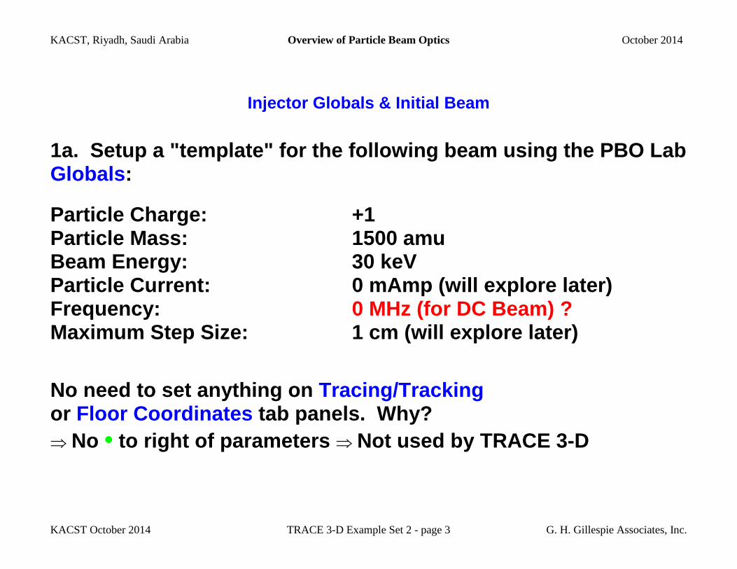
Injector Globals & Initial Beam
1a. Setup a "template" for the following beam using the PBO Lab Globals :
Particle Charge: +1 Particle Mass: 1500 amu Beam Energy: 30 keV Particle Current: 0 mAmp (will explore later) Frequency: 0 MHz (for DC Beam) ? Maximum Step Size: 1 cm (will explore later)
No need to set anything on Tracing/Tracking or Floor Coordinates tab panels. Why? ⇒ No • to right of parameters ⇒ Not used by TRACE 3-D
KACST, Riyadh, Saudi Arabia Overview of Particle Beam Optics October 2014
KACST October 2014 TRACE 3-D Example Set 2 - page 4 G. H. Gillespie Associates, Inc.
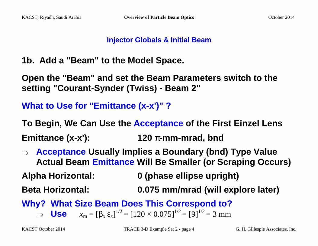
Injector Globals & Initial Beam
1b. Add a "Beam" to the Model Space.
Open the "Beam" and set the Beam Parameters switch to the setting "Courant-Synder (Twiss) - Beam 2"
What to Use for "Emittance (x-x')" ?
To Begin, We Can Use the Acceptance of the First Einzel Lens
Emittance (x-x'): 120 π-mm-mrad, bnd
⇒ Acceptance Usually Implies a Boundary (bnd) Type Value Actual Beam Emittance Will Be Smaller (or Scraping Occurs)
Alpha Horizontal: 0 (phase ellipse upright)
Beta Horizontal: 0.075 mm/mrad (will explore lat er)
Why? W hat Size Beam Does This Correspond to? ⇒ Use xm = [βx εx]
1/2 = [120 × 0.075]1/2 = [9]1/2 = 3 mm
KACST, Riyadh, Saudi Arabia Overview of Particle Beam Optics October 2014
KACST October 2014 TRACE 3-D Example Set 2 - page 5 G. H. Gillespie Associates, Inc.
Injector Globals & Initial Beam
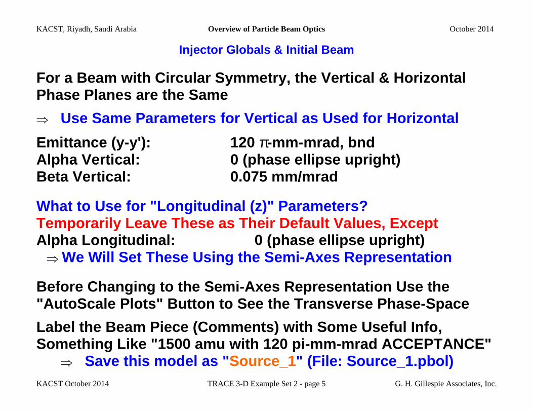
For a Beam with Circular Symmetry, the Vertical & H orizontal Phase Planes are the Same
⇒ Use Same Parameters for Vertical as Used for Horizo ntal
Emittance (y-y'): 120 π-mm-mrad, bnd Alpha Vertical: 0 (phase ellipse upright) Beta Vertical: 0.075 mm/mrad
What to Use for "Longitudinal (z)" Parameters? Temporarily Leave These as Their Default Values, Except Alpha Longitudinal: 0 (phase ellipse upright) ⇒ We Will Set These Using the Semi-Axes Representatio n
Before Changing to the Semi-Axes Representation Use the "AutoScale Plots" Button to See the Transverse Phas e-Space
Label the Beam Piece (Comments) with Some Useful In fo,
Something Like "1500 amu with 120 pi-mm -mrad ACCEPTANCE" ⇒ Save this model as " Source_1 " (File: Source_1.pbol)
KACST, Riyadh, Saudi Arabia Overview of Particle Beam Optics October 2014
KACST October 2014 TRACE 3-D Example Set 2 - page 6 G. H. Gillespie Associates, Inc.
Injector Globals & Initial Beam
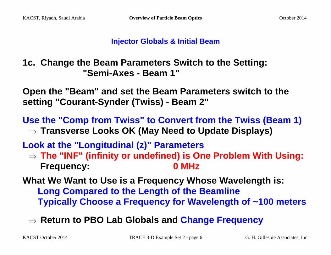
1c. Change the Beam Parameters Switch to the Setti ng: "Semi-Axes - Beam 1"
Open the "Beam" and set the Beam Parameters switch to the setting "Courant-Synder (Twiss) - Beam 2"
Use the "Comp from Twiss" to Convert from the Twiss (Beam 1) ⇒ Transverse Looks OK (May Need to Update Displays)
Look at the "Longitudinal (z)" Parameters ⇒ The "INF" (infinity or undefined) is One Problem Wi th Using: Frequency: 0 MHz
What We Want to Use is a Frequency Whose Wavelength is: Long Compared to the Length of the Beamline Typically Choose a Frequency for Wavelength of ~100 meters
⇒ Return to PBO Lab Globals and Change Frequency
KACST, Riyadh, Saudi Arabia Overview of Particle Beam Optics October 2014
KACST October 2014 TRACE 3-D Example Set 2 - page 7 G. H. Gillespie Associates, Inc.
Injector Globals & Initial Beam
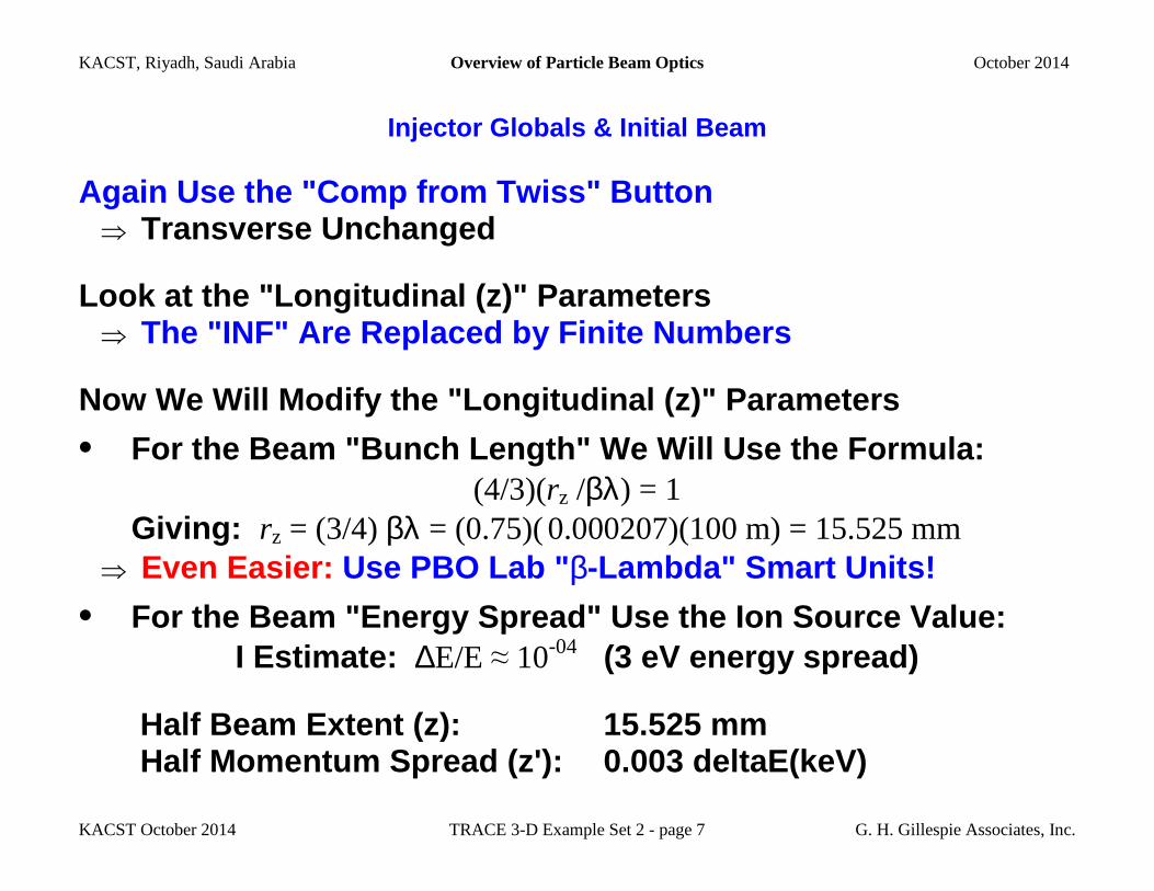
Again Use the "Comp from Twiss" Button ⇒ Transverse Unchanged
Look at the "Longitudinal (z)" Parameters ⇒ The "INF" Are Replaced by Finite Numbers
Now We Will Modify the "Longitudinal (z)" Parameter s
• For the Beam "Bunch Length" We Will Use the Formul a: (4/3)(rz /βλ) = 1 Giving: rz = (3/4) βλ = (0.75)( 0.000207)(100 m) = 15.525 mm ⇒ Even Easier: Use PBO Lab " β-Lambda" Smart Units!
• For the Beam "Energy Spread" Use the Ion Source Va lue: I Estimate: ∆E/E ≈ 10-04 (3 eV energy spread)
Half Beam Extent (z): 15.525 mm Half Momentum Spread (z'): 0.003 deltaE(keV)
KACST, Riyadh, Saudi Arabia Overview of Particle Beam Optics October 2014
KACST October 2014 TRACE 3-D Example Set 2 - page 8 G. H. Gillespie Associates, Inc.
Injector Globals & Initial Beam
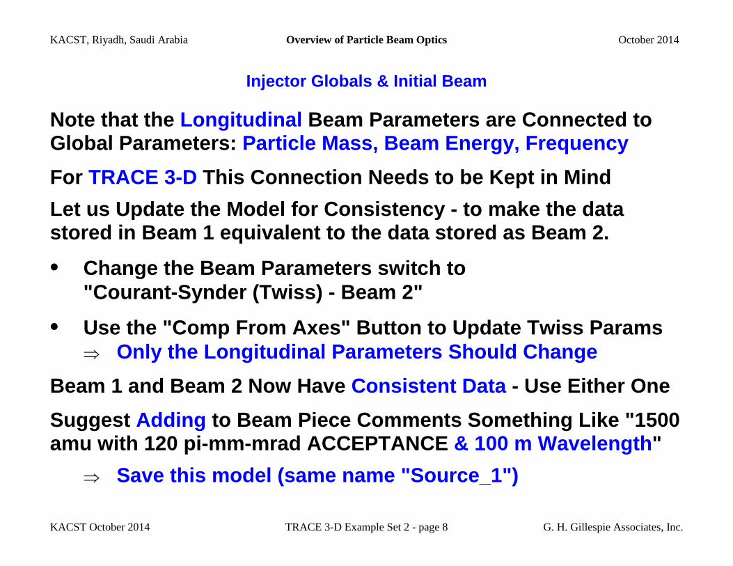
Note that the Longitudinal Beam Parameters are Connected to Global Parameters: Particle Mass, Beam Energy, Frequency
For TRACE 3-D This Connection Needs to be Kept in Mind
Let us Update the Model for Consistency - to make t he data stored in Beam 1 equivalent to the data stored as B eam 2.
• Change the Beam Parameters switch to "Courant-Synder (Twiss) - Beam 2"
• Use the "Comp From Axes" Button to Update Twiss Pa rams
⇒ Only the Longitudinal Parameters Should Change
Beam 1 and Beam 2 Now Have Consistent Data - Use Either One
Suggest Adding to Beam Piece Comments Something Like "1500 amu with 120 pi-mm -mrad ACCEPTANCE & 100 m Wavelength "
⇒ Save this model (same name "Source_1")
KACST, Riyadh, Saudi Arabia Overview of Particle Beam Optics October 2014
KACST October 2014 TRACE 3-D Example Set 2 - page 9 G. H. Gillespie Associates, Inc.
Estimate Location of 1st Focusing Element, Check Sp ace Charge
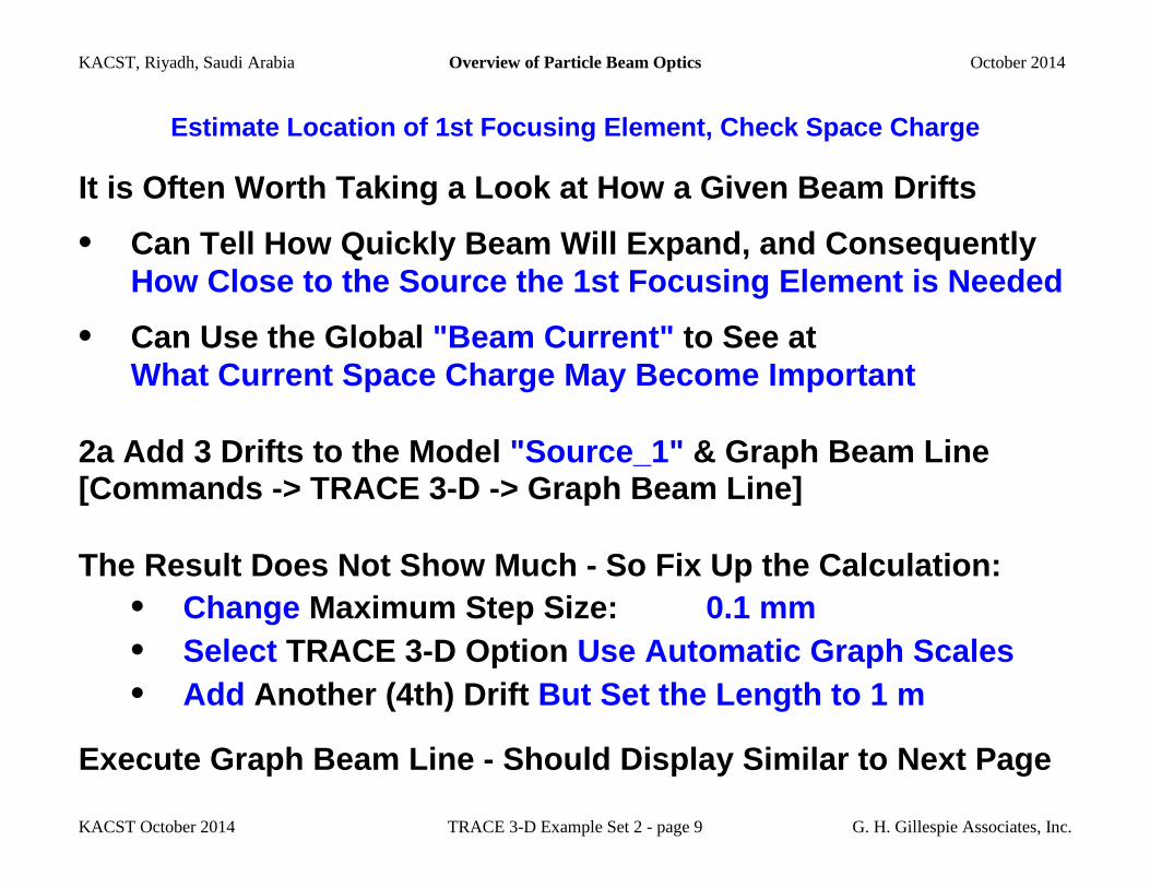
It is Often Worth Taking a Look at How a Given Beam Drifts
• Can Tell How Quickly Beam Will Expand, and Consequ ently How Close to the Source the 1st Focusing Element is Needed
• Can Use the Global "Beam Current" to See at What Current Space Charge May Become Important
2a Add 3 Drifts to the Model "Source_1" & Graph Beam Line [Commands -> TRACE 3-D -> Graph Beam Line]
The Result Does Not Show Much - So Fix Up the Calcu lation: • Change Maximum Step Size: 0.1 mm • Select TRACE 3-D Option Use Automatic Graph Scales • Add Another (4th) Drift But Set the Length to 1 m
Execute Graph Beam Line - Should Display Similar to Next Page
KACST, Riyadh, Saudi Arabia Overview of Particle Beam Optics October 2014
KACST October 2014 TRACE 3-D Example Set 2 - page 10 G. H. Gillespie Associates, Inc.
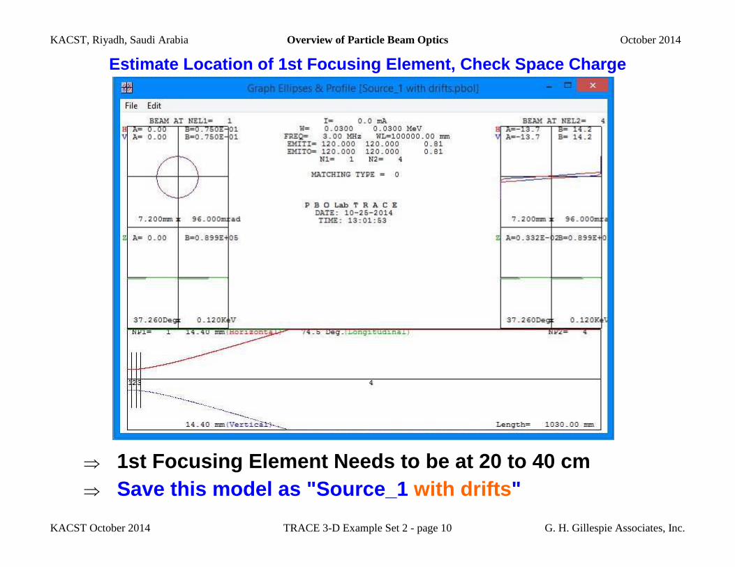
Estimate Location of 1st Focusing Element, Check Sp ace Charge
⇒ 1st Focusing Element Needs to be at 20 to 40 cm
⇒ Save this model as "Source_1 with drifts "
KACST, Riyadh, Saudi Arabia Overview of Particle Beam Optics October 2014
KACST October 2014 TRACE 3-D Example Set 2 - page 11 G. H. Gillespie Associates, Inc.
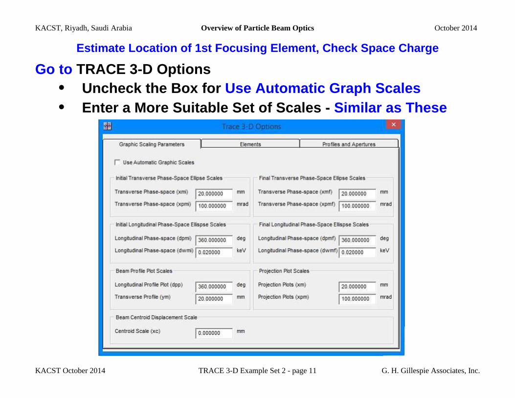
Estimate Location of 1st Focusing Element, Check Sp ace Charge
Go to TRACE 3-D Options • Uncheck the Box for Use Automatic Graph Scales • Enter a More Suitable Set of Scales - Similar as These
KACST, Riyadh, Saudi Arabia Overview of Particle Beam Optics October 2014
KACST October 2014 TRACE 3-D Example Set 2 - page 12 G. H. Gillespie Associates, Inc.
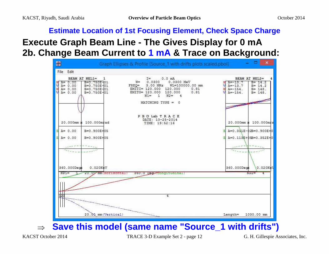
Estimate Location of 1st Focusing Element, Check Sp ace Charge
Execute Graph Beam Line - The Gives Display for 0 m A 2b. Change Beam Current to 1 mA & Trace on Background:
⇒ Save this model (same name "Source_1 with drifts")
KACST, Riyadh, Saudi Arabia Overview of Particle Beam Optics October 2014
KACST October 2014 TRACE 3-D Example Set 2 - page 13 G. H. Gillespie Associates, Inc.
Einzel Lens as 1st Focusing Element
3a. Set a Tentative Location for the 1st Focusing E lement • Move ("Shift-Click") the 1 meter Drift to Work Space • Delete 2 of the remaining 3 Drifts - • For the one remaining Drift Piece: - Assign a label " D1" to the Comment Field - Effective Drift Length: 30 cm
Set the Beam Current to 0 mA and execute Graph Beam Line ⇒ Graph Should Be Similar, but Shorter, to Prior Run: Beam Expands to About 12 mm at the End of D1
• Drag the 1 meter Drift (on Work Space) to after D1
⇒ Save this model as "Source_1 with D1 "
(The Desired Beam Focus is Assumed to be at 1300 mm , Adjust the "meter" Drift as Necessary for a Differe nt Location.)
KACST, Riyadh, Saudi Arabia Overview of Particle Beam Optics October 2014
KACST October 2014 TRACE 3-D Example Set 2 - page 14 G. H. Gillespie Associates, Inc.
Einzel Lens as 1st Focusing Element
3b. Adding an Einzel Lens as 1st Focusing Element
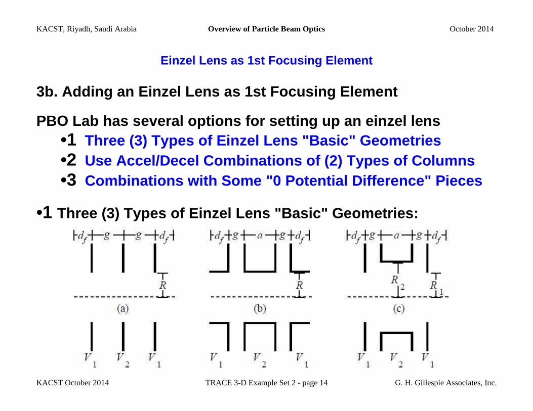
PBO Lab has several options for setting up an einze l lens •1 Three (3) Types of Einzel Lens "Basic" Geometries •2 Use Accel/Decel Combinations of (2) Types of Column s •3 Combinations with Some "0 Potential Difference" Pie ces
•1 Three (3) Types of Einzel Lens "Basic" Geometries:
KACST, Riyadh, Saudi Arabia Overview of Particle Beam Optics October 2014
KACST October 2014 TRACE 3-D Example Set 2 - page 15 G. H. Gillespie Associates, Inc.
Einzel Lens as 1st Focusing Element
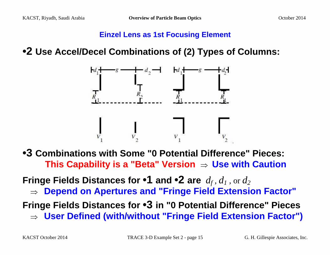
•2 Use Accel/Decel Combinations of (2) Types of Column s:
•3 Combinations with Some "0 Potential Difference" Pie ces: This Capability is a "Beta" Version ⇒ Use with Caution
Fringe Fields Distances for •1 and •2 are df , d1 , or d2 ⇒ Depend on Apertures and "Fringe Field Extension Fac tor"
Fringe Fields Distances for •3 in "0 Potential Difference" Pieces ⇒ User Defined (with/without "Fringe Field Extension Factor")
KACST, Riyadh, Saudi Arabia Overview of Particle Beam Optics October 2014
KACST October 2014 TRACE 3-D Example Set 2 - page 16 G. H. Gillespie Associates, Inc.
Einzel Lens as 1st Focusing Element
Which Approach to Use: •1, •2, or •3?
Start w ith the Simplest Approach
⇒ Select geometry choice from •1 that is Closest to Design
Later, use approaches •2 and •3 to develop alternate models
Compare results from models to see if differences i mportant
KACST, Riyadh, Saudi Arabia Overview of Particle Beam Optics October 2014
KACST October 2014 TRACE 3-D Example Set 2 - page 17 G. H. Gillespie Associates, Inc.
Einzel Lens as 1st Focusing Element
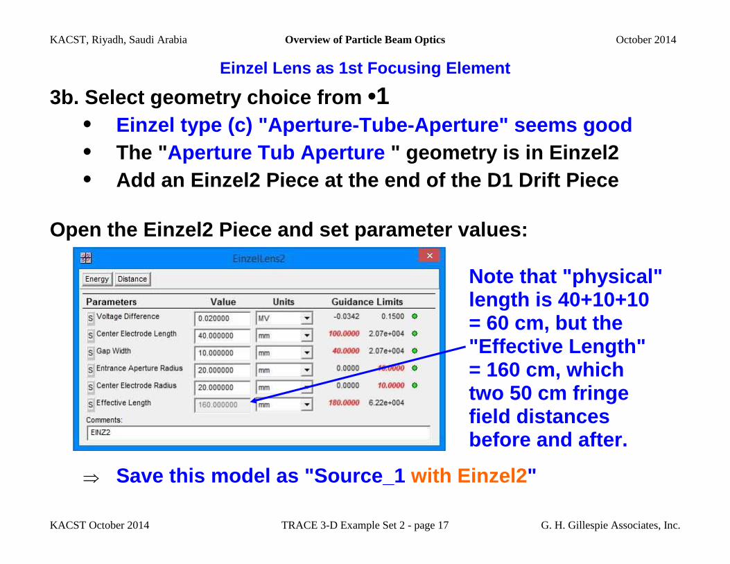
3b. Select geometry choice from •1 • Einzel type (c) "Aperture-Tube-Aperture" seems good • The " Aperture Tub Aperture " geometry is in Einzel2 • Add an Einzel2 Piece at the end of the D1 Drift Pi ece
Open the Einzel2 Piece and set parameter values: Note that "physical" length is 40+10+10 = 60 cm, but the
"Effective Length"
= 160 cm, which two 50 cm fringe field distances before and after.
⇒ Save this model as "Source_1 with Einzel2 "
KACST, Riyadh, Saudi Arabia Overview of Particle Beam Optics October 2014
KACST October 2014 TRACE 3-D Example Set 2 - page 18 G. H. Gillespie Associates, Inc.
Einzel Lens as 1st Focusing Element
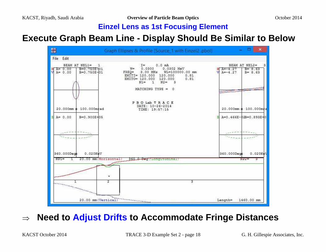
Execute Graph Beam Line - Display Should Be Similar to Below
⇒ Need to Adjust Drifts to Accommodate Fringe Distances
KACST, Riyadh, Saudi Arabia Overview of Particle Beam Optics October 2014
KACST October 2014 TRACE 3-D Example Set 2 - page 19 G. H. Gillespie Associates, Inc.
Einzel Lens as 1st Focusing Element
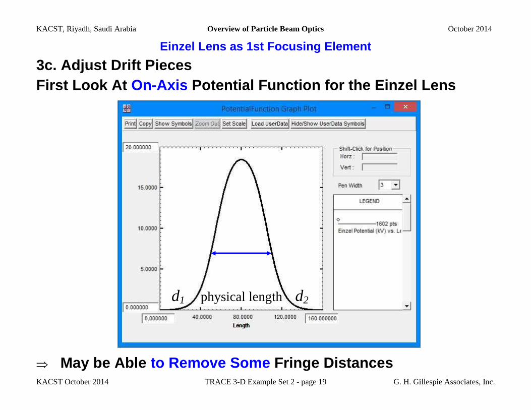
3c. Adjust Drift Pieces
First Look At On-Axis Potential Function for the Einzel Lens
d1 physical length d2
⇒ May be Able to Remove Some Fringe Distances
KACST, Riyadh, Saudi Arabia Overview of Particle Beam Optics October 2014
KACST October 2014 TRACE 3-D Example Set 2 - page 20 G. H. Gillespie Associates, Inc.
Einzel Lens as 1st Focusing Element
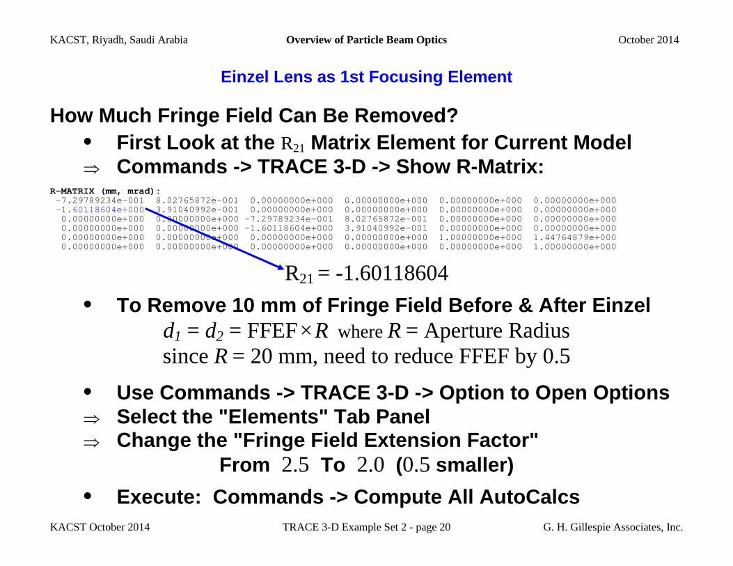
How Much Fringe Field Can Be Removed? • First Look at the R21 Matrix Element for Current Model ⇒ Commands -> TRACE 3-D -> Show R-Matrix:
R-MATRIX (mm, mrad): -7.29789234e-001 8.02765872e-001 0.00000000e+000 0.00000000e+000 0.00000000e+000 0.00000000e+000 -1.60118604e+000 3.91040992e-001 0.00000000e+000 0.00000000e+000 0.00000000e+000 0.00000000e+000 0.00000000e+000 0.00000000e+000 -7.29789234e-001 8.02765872e-001 0.00000000e+000 0.00000000e+000 0.00000000e+000 0.00000000e+000 -1.60118604e+000 3.91040992e-001 0.00000000e+000 0.00000000e+000 0.00000000e+000 0.00000000e+000 0.00000000e+000 0.00000000e+000 1.00000000e+000 1.44764879e+000 0.00000000e+000 0.00000000e+000 0.00000000e+000 0.00000000e+000 0.00000000e+000 1.00000000e+000
R21 = -1.60118604
• To Remove 10 mm of Fringe Field Before & After Ein zel d1 = d2 = FFEF × R where R = Aperture Radius
since R = 20 mm, need to reduce FFEF by 0.5
• Use Commands -> TRACE 3-D -> Option to Open Option s ⇒ Select the "Elements" Tab Panel ⇒ Change the "Fringe Field Extension Factor"
From 2.5 To 2.0 (0.5 smaller)
• Execute: Commands -> Compute All AutoCalcs
KACST, Riyadh, Saudi Arabia Overview of Particle Beam Optics October 2014
KACST October 2014 TRACE 3-D Example Set 2 - page 21 G. H. Gillespie Associates, Inc.
Einzel Lens as 1st Focusing Element
How Much Fringe Field Can Be Removed? (continued)
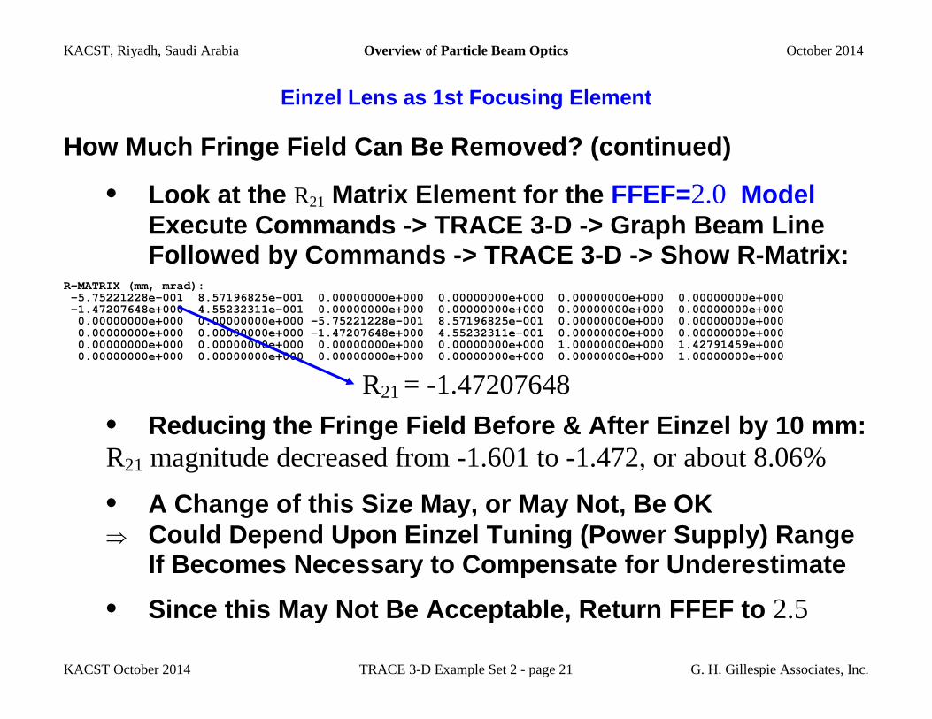
• Look at the R21 Matrix Element for the FFEF=2.0 Model Execute Commands -> TRACE 3-D -> Graph Beam Line Followed by Commands -> TRACE 3-D -> Show R-Matrix:
R-MATRIX (mm, mrad): -5.75221228e-001 8.57196825e-001 0.00000000e+000 0.00000000e+000 0.00000000e+000 0.00000000e+000 -1.47207648e+000 4.55232311e-001 0.00000000e+000 0.00000000e+000 0.00000000e+000 0.00000000e+000 0.00000000e+000 0.00000000e+000 -5.75221228e-001 8.57196825e-001 0.00000000e+000 0.00000000e+000 0.00000000e+000 0.00000000e+000 -1.47207648e+000 4.55232311e-001 0.00000000e+000 0.00000000e+000 0.00000000e+000 0.00000000e+000 0.00000000e+000 0.00000000e+000 1.00000000e+000 1.42791459e+000 0.00000000e+000 0.00000000e+000 0.00000000e+000 0.00000000e+000 0.00000000e+000 1.00000000e+000
R21 = -1.47207648
• Reducing the Fringe Field Before & After Einzel by 10 mm: R21 magnitude decreased from -1.601 to -1.472, or about 8.06%
• A Change of this Size May, or May Not, Be OK ⇒ Could Depend Upon Einzel Tuning (Power Supply) Rang e If Becomes Necessary to Compensate for Underestim ate
• Since this May Not Be Acceptable, Return FFEF to 2.5
KACST, Riyadh, Saudi Arabia Overview of Particle Beam Optics October 2014
KACST October 2014 TRACE 3-D Example Set 2 - page 22 G. H. Gillespie Associates, Inc.
Einzel Lens as 1st Focusing Element
3c. Adjust Drift Pieces (continued) • Generally Want to Reduce Drifts on Each Side of Ei nzel ⇒ To Compensate for the "drifts" Produced by FFEF × R • Since FFEF × R = 50 mm Want to Reduce Drifts by 5 cm ⇒ Change D1 to 25 cm, Change "meter" Drift to 95 cm
• Also Want to Reduce "meter" Drift by "physical" Length ⇒ Further Reduce "meter" Drift Down to 89 cm
⇒ Save this model (same name "Source_1 with Einzel2")
• Can Compare This Model Directly to "Source_1 with D1" ⇒ Models Have Same Overall Length: 1300 mm (Focus Pt.)

KACST, Riyadh, Saudi Arabia Overview of Particle Beam Optics October 2014
KACST October 2014 TRACE 3-D Example Set 2 - page 23 G. H. Gillespie Associates, Inc.
Einzel Lens as 1st Focusing Element
3d. Find Einzel Center Electrode Potential to Focus at 1300 mm • Will Use a Point-to-Point Fitting Constraint ⇒ Constraint ("Match Specification") To Use is R12 = 0 • Do We Also Need a Similar "y" Constraint R34 = 0 ? ⇒ No. Why Not? • TRACE 3-D Match Specification Sets Constraint R12 = 0 ⇒ Use Commands -> TRACE 3-D -> Match Specification to Open the Match Specification Window • Select ⇒ Use Commands -> TRACE 3-D -> Match Specification to Open the Match Specification Window (on Next P age)
KACST, Riyadh, Saudi Arabia Overview of Particle Beam Optics October 2014
KACST October 2014 TRACE 3-D Example Set 2 - page 24 G. H. Gillespie Associates, Inc.
Einzel Lens as 1st Focusing Element
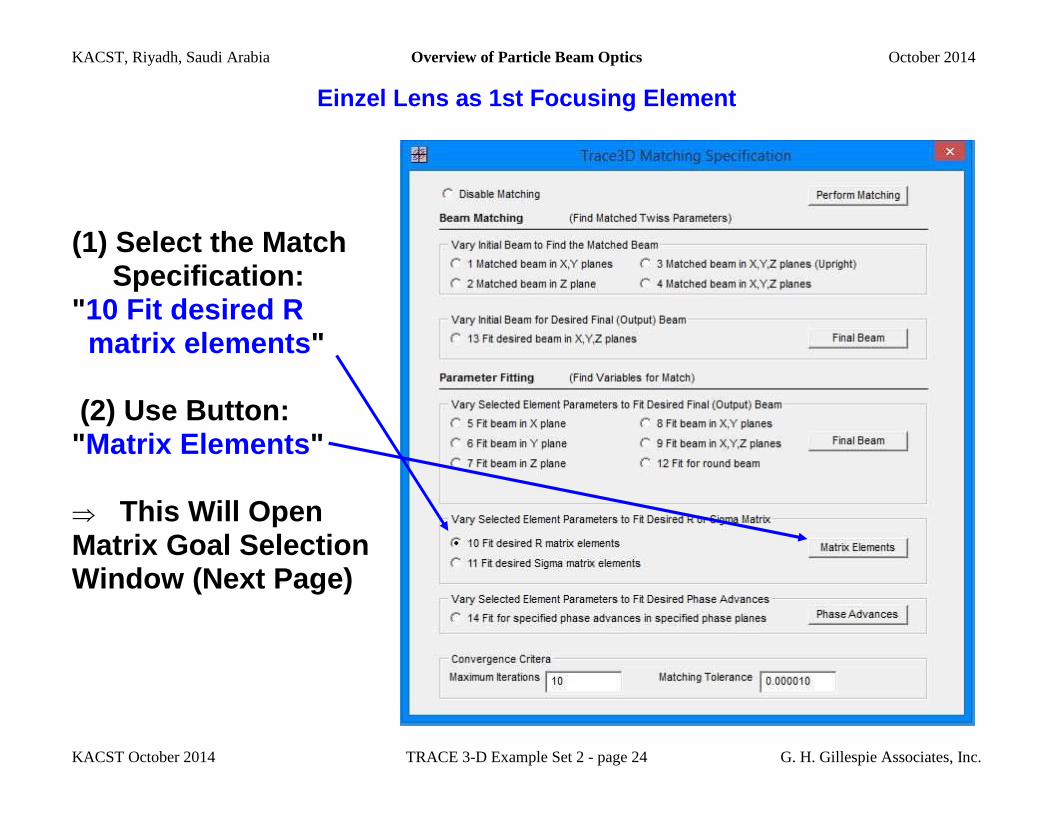
(1) Select the Match Specification: "10 Fit desired R matrix elements " (2) Use Button: "Matrix Elements " ⇒ This Will Open Matrix Goal Selection Window (Next Page)
KACST, Riyadh, Saudi Arabia Overview of Particle Beam Optics October 2014
KACST October 2014 TRACE 3-D Example Set 2 - page 25 G. H. Gillespie Associates, Inc.
Einzel Lens as 1st Focusing Element
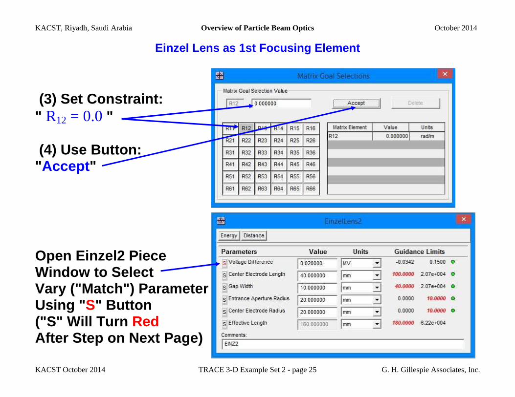
(3) Set Constraint: " R12 = 0.0 " (4) Use Button: "Accept "
Open Einzel2 Piece Window to Select Vary ("Match") Parameter Using " S" Button ("S" Will Turn Red After Step on Next Page)
KACST, Riyadh, Saudi Arabia Overview of Particle Beam Optics October 2014
KACST October 2014 TRACE 3-D Example Set 2 - page 26 G. H. Gillespie Associates, Inc.
Einzel Lens as 1st Focusing Element
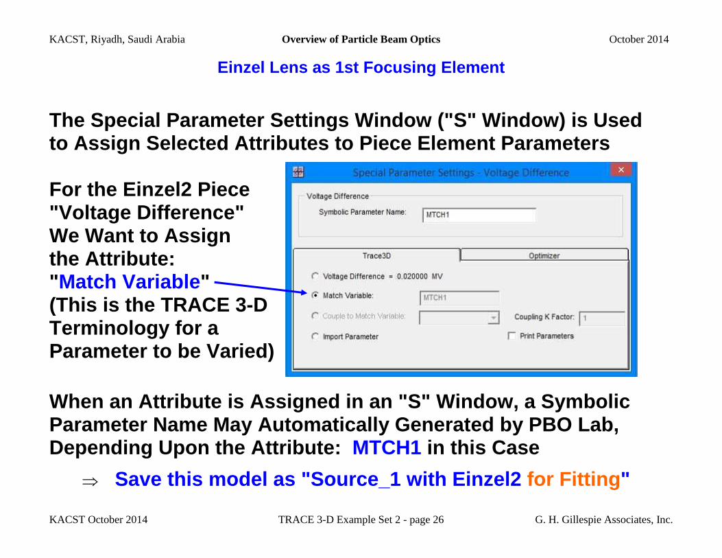
The Special Parameter Settings Window ("S" Window) is Used to Assign Selected Attributes to Piece Element Para meters For the Einzel2 Piece "Voltage Difference" We Want to Assign the Attribute: "Match Variable " (This is the TRACE 3-D Terminology for a Parameter to be Varied)
When an Attribute is Assigned in an "S" Window , a Symbolic Parameter Name May Automatically Generated by PBO L ab, Depending Upon the Attribute: MTCH1 in this Case
⇒ Save this model as "Source_1 with Einzel2 for Fitting "
KACST, Riyadh, Saudi Arabia Overview of Particle Beam Optics October 2014
KACST October 2014 TRACE 3-D Example Set 2 - page 27 G. H. Gillespie Associates, Inc.
Einzel Lens as 1st Focusing Element
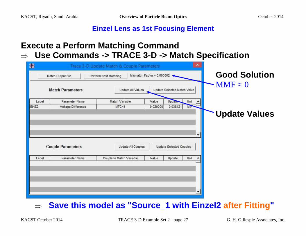
Execute a Perform Matching Command ⇒ Use Commands -> TRACE 3-D -> Match Specification Good Solution MMF ≈ 0 Update Values
⇒ Save this model as "Source_1 with Einzel2 after Fitting "
KACST, Riyadh, Saudi Arabia Overview of Particle Beam Optics October 2014
KACST October 2014 TRACE 3-D Example Set 2 - page 28 G. H. Gillespie Associates, Inc.
Einzel Lens as 1st Focusing Element
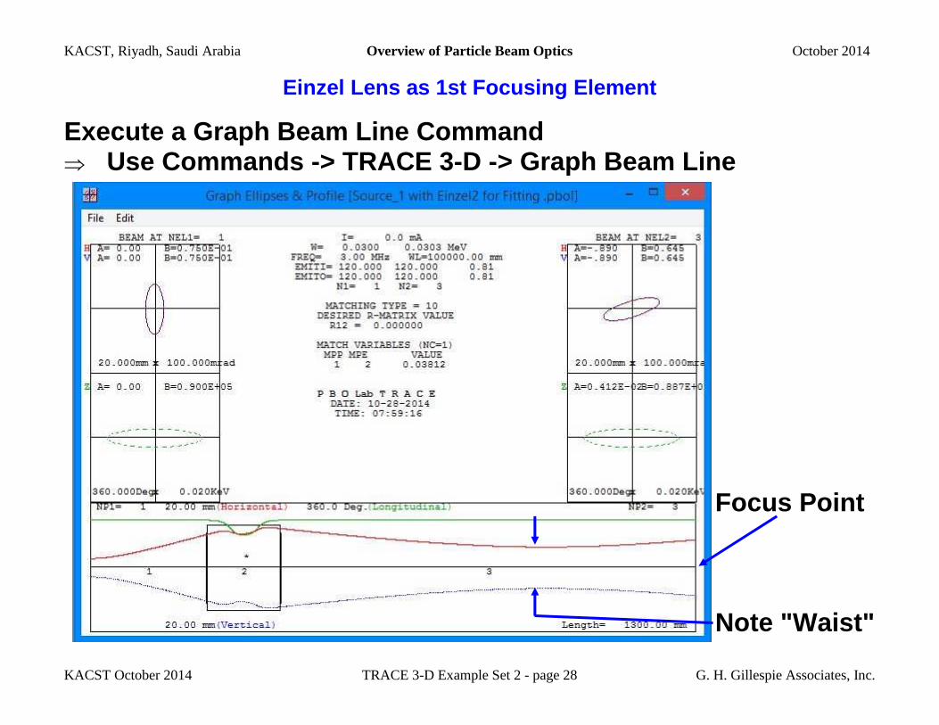
Execute a Graph Beam Line Command ⇒ Use Commands -> TRACE 3-D -> Graph Beam Line
Focus Point Note "Waist"
KACST, Riyadh, Saudi Arabia Overview of Particle Beam Optics October 2014
KACST October 2014 TRACE 3-D Example Set 2 - page 29 G. H. Gillespie Associates, Inc.
Einzel Lens as 1st Focusing Element
• A Point Focus Constraint, e.g. a Point-to-Point Fo cus such as R12 = 0, Gives the Smallest Spot at Focus Point
• The Spot Size is Determined by the Beam Emittance
• A Smaller Spot Size will be Upstream of the Focus Point The Smaller Spot Size will be at a Beam "Waist"
• It is Tempting to Think That by Fitting a Waist Co ndition (r12 = 0, σ12 = 0, or αx = 0) a Smaller Spot May be Achieve at the Focus Point - This is Not Correct
• As the Beam Waist is Moved Out to the Focus Point It Increases in Size Such that it Will Be Larger than (Smallest) Spot Size Obtained in the Point Focus
• This is Illustrated Explicitly on the Next Page Wh ere a Waist Fit ( αx = 0) is Compared to the Point Fit ( R12 = 0)
(Details Left as an Exercise to the Reader )
KACST, Riyadh, Saudi Arabia Overview of Particle Beam Optics October 2014
KACST October 2014 TRACE 3-D Example Set 2 - page 30 G. H. Gillespie Associates, Inc.
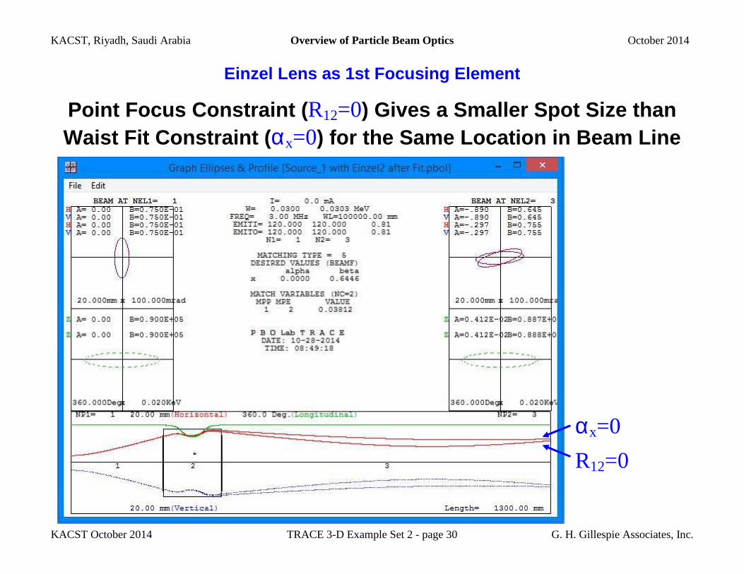
Einzel Lens as 1st Focusing Element
Point Focus Constraint ( R12=0) Gives a Smaller Spot Size than Waist Fit Constraint ( αx=0) for the Same Location in Beam Line
αx=0
R12=0 u