trace-based framework for concurrent development of process and fpga architecture considering...
Post on 22-Dec-2015
215 views
TRANSCRIPT

Trace-Based Framework for Concurrent Development of Process and FPGA
Architecture Considering Process Variationand Reliability
Trace-Based Framework for Concurrent Development of Process and FPGA
Architecture Considering Process Variationand Reliability
1Lerong Cheng, 1Yan Lin, 1Lei He, and 2Yu Cao
1EE Department, UCLA2EE Department, ASU
Address comments to [email protected]

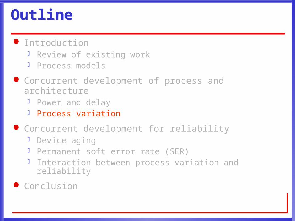
OutlineOutline
Introduction Review of existing work Process models
Concurrent development of process and architecture Power and delay Process variation
Concurrent development for reliability Device aging Permanent soft error rate (SER) Interaction between process variation and reliability
Conclusion
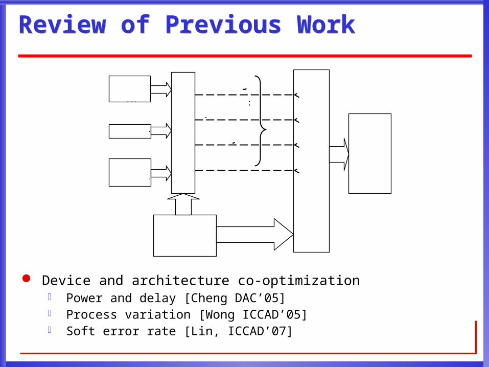
Review of Previous WorkReview of Previous Work
Device and architecture co-optimization Power and delay [Cheng DAC’05] Process variation [Wong ICCAD’05] Soft error rate [Lin, ICCAD’07]
VPRand
Psim
Circuit LevelDelay, Power
and Area
Ptrace
ChipLevelDelay,Power,
and Area
Circuitelement usage
Short circuitpower ratio
Switchingactivity
Critical pathstructure
Trace
ApplicationBenchmark
Set
Input Vector
FPGAArchitecture

Limitation of PtraceLimitation of Ptrace
Ptrace requires a stable SPICE model which is able to consider all process corners SPICE model is not available at the early stage of process
development
Circuit simulation for all process corners is time consuming The accuracy of circuit simulation is not needed for quick
architecture evaluation
Does not handle realistic variation Non-Gaussian variation sources Spatial correlation
Does not handle device aging
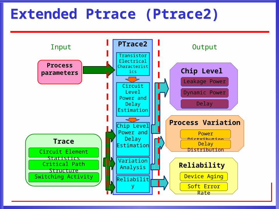
Extended Ptrace (Ptrace2)Extended Ptrace (Ptrace2)
TraceCircuit Element Statistics
Critical Path Structure
Switching Activity
Process parameters Chip Level
Leakage Power
Dynamic Power
Delay
Reliability
Soft Error Rate
Device Aging
Process Variation
Power Distribution
Delay Distribution
Input OutputPTrace2
Reliability
Chip Level Power and
Delay Estimation
Variation Analysis
Circuit Level Power and
Delay Estimation
Transistor Electrical
Characteristics

Early-Stage Circuit ModelingEarly-Stage Circuit Modeling
ITRS MASTAR4 model [ITRS MASTAR4 2005]
Inputs: Lgate Tox Nbulk Xjext W Racc T Vdd
Outputs: Ioff Ion Igon Igoff Cg Cdiff
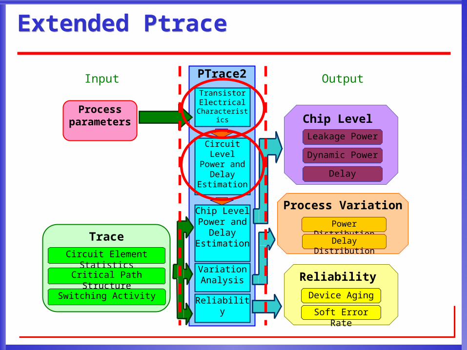
Extended PtraceExtended Ptrace
TraceCircuit Element Statistics
Critical Path Structure
Switching Activity
Process parameters Chip Level
Leakage Power
Dynamic Power
Delay
Reliability
Soft Error Rate
Device Aging
Process Variation
Power Distribution
Delay Distribution
Input OutputPTrace2
Reliability
Chip Level Power and
Delay Estimation
Variation Analysis
Circuit Level Power and
Delay Estimation
Transistor Electrical
Characteristics

Circuit Level and Chip Level Power and DelayCircuit Level and Chip Level Power and Delay
Circuit level power and delay Inverter Pass transistor driven by an inverter
Chip level power and delay Similar to the original Ptrace [Cheng DAC’05, Wong ICCAD’05]

OutlineOutline
Introduction Review of existing work Process models
Concurrent development of process and architecture Power and delay Process variation
Concurrent development for reliability Device aging Permanent soft error rate (SER) Interaction between process variation and reliability
Conclusion

Experimental SettingExperimental Setting
20 MCNC benchmarks Assume all 20 MCNC benchmarks are placed in the same chip
ITRS high performance 32nm technology (HP32)
Architecture Cluster size N=6 LUT size K=7 Wire segment length W=4
Device Vdd=1.0, 1.05, 1.1 V Lgate=31, 32, 33 nm
Baseline ITRS HP32

Delay and Power TradeoffDelay and Power Tradeoff
3.1X energy span and 1.3X delay span within search space

Power and Delay OptimizationPower and Delay Optimization
Device Power (W)
Delay (ns)
Energy (nJ)
ED (nJ·ns)
HP32 1.19 3.90 1.88 22.6
Min-ED 0.77 4.55 3.50 15.9(-29.4%)
Device tuning reduces energy delay product by 29.4%
OutlineOutline
Introduction Review of existing work Process models
Concurrent development of process and architecture Power and delay Process variation
Concurrent development for reliability Device aging Permanent soft error rate (SER) Interaction between process variation and reliability
Conclusion
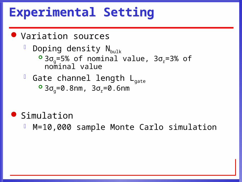
Experimental SettingExperimental Setting
Variation sources Doping density Nbulk
3σg=5% of nominal value, 3σr=3% of nominal value Gate channel length Lgate
3σg=0.8nm, 3σr=0.6nm
Simulation M=10,000 sample Monte Carlo simulation

Power and Delay DistributionPower and Delay Distribution

Power and Delay VariationPower and Delay Variation
Min-ED device setting significantly reduce leakage variation with a small increase of delay variation
DeviceLeakage (mW) Delay (ns)
µ σ µ σ
HP32 942 334 3.91 0.119
Min-ED 340 45 (-87%) 4.550.159
(+34%)

OutlineOutline
Introduction Review of existing work Process models
Concurrent development of process and architecture Power and delay Process variation
Concurrent development for reliability Device aging Permanent soft error rate (SER) Interaction between process variation and reliability
Conclusion

NBTI and HCINBTI and HCI
Negative-bias-temperature-instability (NBTI) effect increases the threshold voltage of PMOS [Wang DAC’06]
hot-carrier-injection (HCI) increases the threshold voltage of NMOS [Wang CICC’07]
Inputs: Lgate Tox Nbulk Xjext W Racc T Vdd
Outputs: ΔVth(NBTI) ΔVth(HCI)

Vth Increase Caused by NBTI and HCIVth Increase Caused by NBTI and HCI
Vth increase is the most significant in the first year
Device burn-in can be applied to reduce the impact of device aging
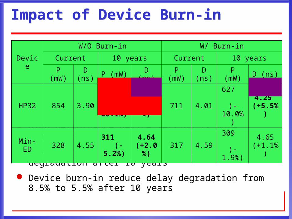
Impact of Device Burn-inImpact of Device Burn-in
High performance device setting is more sensitive to device aging
Device aging leads to 8.5% of delay degradation after 10 years
Device burn-in reduce delay degradation from 8.5% to 5.5% after 10 years
Device
W/O Burn-in W/ Burn-in
Current 10 years Current 10 years
P (mW)
D (ns) P (mW) D (ns) P
(mW)D
(ns) P (mW) D (ns)
HP32 854 3.90640
(-25.1%)
4.23 (+8.5%
)711 4.01
627 (-
10.0%)
4.25 (+5.5%)
Min-ED 328 4.55 311 (-5.2%)
4.64 (+2.0%
)317 4.59 309
(-1.9%)4.65
(+1.1%)

OutlineOutline
Introduction Review of existing work Process models
Concurrent development of process and architecture Power and delay Process variation
Concurrent development for reliability Device aging Permanent soft error rate (SER) Interaction between process variation and reliability
Conclusion

Permanent Soft Error RatePermanent Soft Error Rate
Single-event upset (SEU) due to cosmic rays or high energy particles may affect configuration SRAMs in FPGAs and result in permanent soft error
Inputs: Lgate Tox Nbulk Xjext W Racc T Vdd
Outputs: SER

SER under Different Device SettingSER under Different Device Setting
SER for both device setting is similar
Device SER (FIT)
HP32 362.45
Min-ED 368.25 (+1.6%)
OutlineOutline
Introduction Review of existing work Process models
Concurrent development of process and architecture Power and delay Process variation
Concurrent development for reliability Device aging Permanent soft error rate (SER) Interaction between process variation and reliability
Conclusion

Impact of Device Aging on Power and Delay VariationImpact of Device Aging on Power and Delay Variation
Device aging significantly reduces leakage variation and slightly increase delay variation
Deviceσ Leakage (W) σ Delay (ns)
Current 10 years Current 10 years
HP32 334116 (-65.2%) 0.119 0.121 (+1.67%)
Min-ED 45.030.3(-32.7%) 0.159 0.159 (+0.16%)
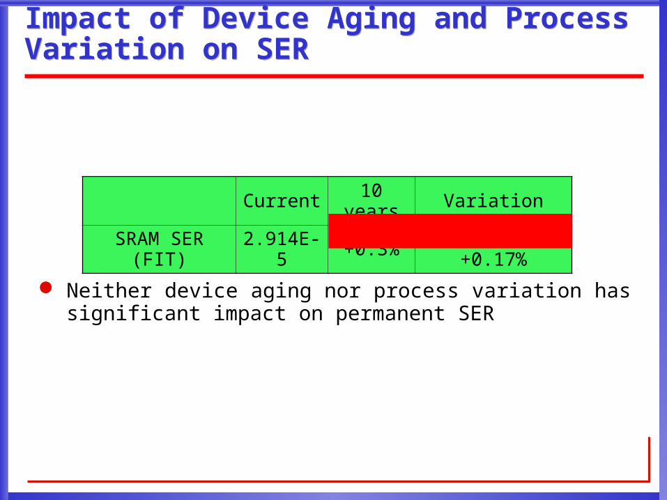
Impact of Device Aging and Process Variation on SERImpact of Device Aging and Process Variation on SER
Neither device aging nor process variation has significant impact on permanent SER
Current 10 years Variation
SRAM SER (FIT) 2.914E-5 +0.3% -0.18% ~ +0.17%

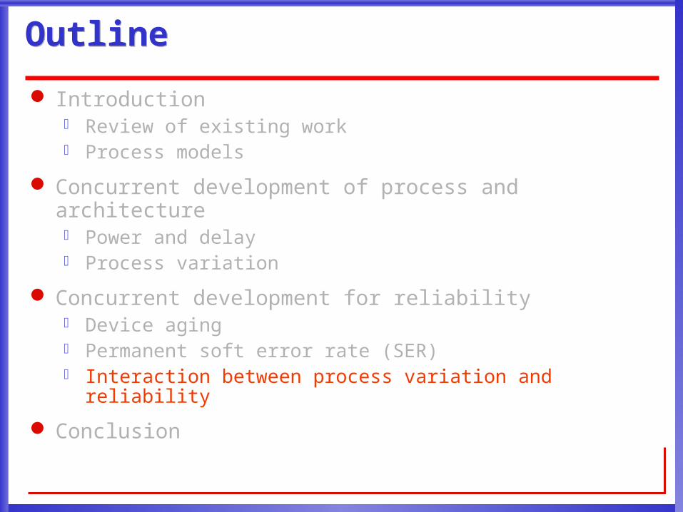
OutlineOutline
Introduction Review of existing work Process models
Concurrent development of process and architecture Power and delay Process variation
Concurrent development for reliability Device aging Permanent soft error rate (SER) Interaction between process variation and reliability
Conclusion
ConclusionConclusion
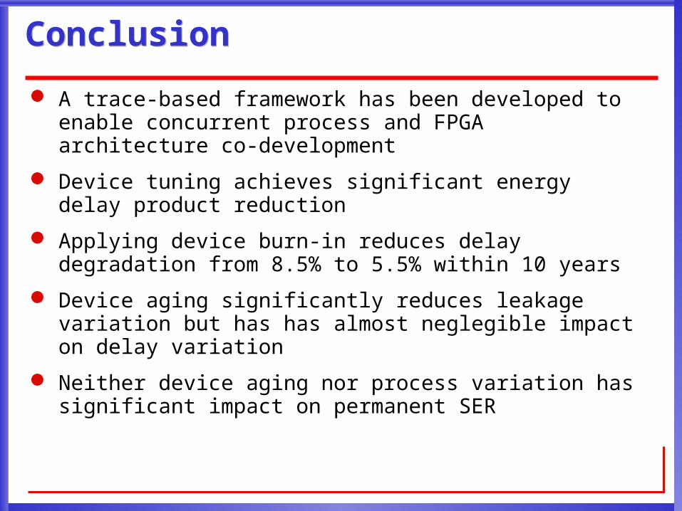
A trace-based framework has been developed to enable concurrent process and FPGA architecture co-development
Device tuning achieves significant energy delay product reduction
Applying device burn-in reduces delay degradation from 8.5% to 5.5% within 10 years
Device aging significantly reduces leakage variation but has has almost neglegible impact on delay variation
Neither device aging nor process variation has significant impact on permanent SER
