tracerco™ radiation monitor - alara consultantsalaraconsultants.com/images/resources... · the...
TRANSCRIPT

TRACERCO™ Radiation Monitor
Instruction and MaintenanceManual for Model No. T402
Customer Notice:Please note that the T402 is NOT an Intrinsically SafeMonitor and should not be confused with theTRACERCO™ T202 Radiation Doserate Monitorwhich does meet Intrinsic Safety Standards.
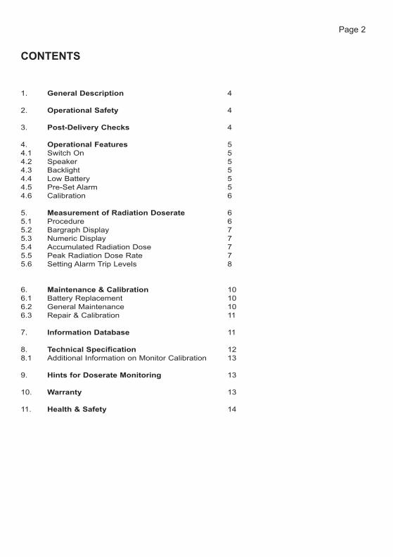
CONTENTS
1. General Description 4
2. Operational Safety 4
3. Post-Delivery Checks 4
4. Operational Features 54.1 Switch On 54.2 Speaker 54.3 Backlight 54.4 Low Battery 54.5 Pre-Set Alarm 54.6 Calibration 6
5. Measurement of Radiation Doserate 65.1 Procedure 65.2 Bargraph Display 75.3 Numeric Display 75.4 Accumulated Radiation Dose 75.5 Peak Radiation Dose Rate 75.6 Setting Alarm Trip Levels 8
6. Maintenance & Calibration 106.1 Battery Replacement 106.2 General Maintenance 106.3 Repair & Calibration 11
7. Information Database 11
8. Technical Specification 128.1 Additional Information on Monitor Calibration 13
9. Hints for Doserate Monitoring 13
10. Warranty 13
11. Health & Safety 14
Page 2
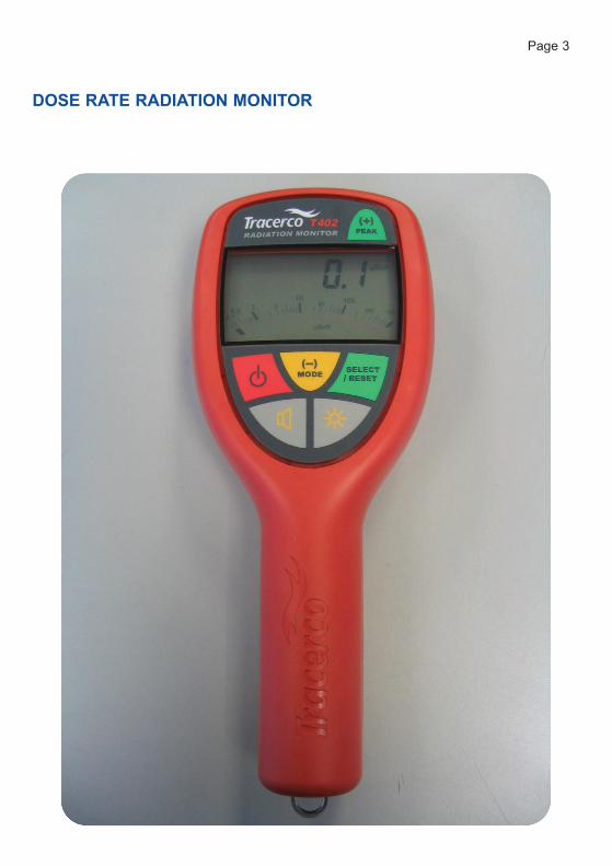
DOSE RATE RADIATION MONITOR
Page 3
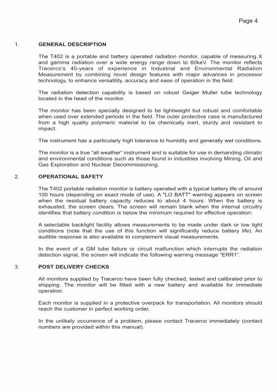
1. GENERAL DESCRIPTION
The T402 is a portable and battery operated radiation monitor, capable of measuring Xand gamma radiation over a wide energy range down to 60keV. The monitor reflectsTracerco’s 40-years of experience in Industrial and Environmental RadiationMeasurement by combining novel design features with major advances in processortechnology, to enhance versatility, accuracy and ease of operation in the field.
The radiation detection capability is based on robust Geiger Muller tube technologylocated in the head of the monitor.
The monitor has been specially designed to be lightweight but robust and comfortablewhen used over extended periods in the field. The outer protective case is manufacturedfrom a high quality polymeric material to be chemically inert, sturdy and resistant toimpact.
The instrument has a particularly high tolerance to humidity and generally wet conditions.
The monitor is a true “all weather” instrument and is suitable for use in demanding climaticand environmental conditions such as those found in industries involving Mining, Oil andGas Exploration and Nuclear Decommissioning.
2. OPERATIONAL SAFETY
The T402 portable radiation monitor is battery operated with a typical battery life of around100 hours (depending on exact mode of use). A "LO BATT" warning appears on screenwhen the residual battery capacity reduces to about 4 hours. When the battery isexhausted, the screen clears. The screen will remain blank when the internal circuitryidentifies that battery condition is below the minimum required for effective operation:
A selectable backlight facility allows measurements to be made under dark or low lightconditions (note that the use of this function will significantly reduce battery life). Anaudible response is also available to complement visual measurements.
In the event of a GM tube failure or circuit malfunction which interrupts the radiationdetection signal, the screen will indicate the following warning message “ERR1”.
3. POST DELIVERY CHECKS
All monitors supplied by Tracerco have been fully checked, tested and calibrated prior toshipping. The monitor will be fitted with a new battery and available for immediateoperation.
Each monitor is supplied in a protective overpack for transportation. All monitors shouldreach the customer in perfect working order.
In the unlikely occurrence of a problem, please contact Tracerco immediately (contactnumbers are provided within this manual).
Page 4

PLEASE ENSURE THAT THE MONITOR RADIATION TEST AND CALIBRATIONCERTIFICATE IS PRESENT IN THE PACK.
(Certificates should be filed in a safe place for future reference. In the event of difficulties,duplicate certificates can be provided by Tracerco free of charge).
4. OPERATIONAL FEATURESThe operator may also wish to refer to the functionality image in the front of this manual.
In certain parts of the world, natural background radiation values may be anomalously lowe.g. Middle East and the operator may conclude that the monitor is non-operational. Tominimise this risk, the monitor is programmed to recognise the following situations:
1. No recorded counts over a period of 20 seconds – the monitor will display a “loBGnd” message on the screen.
2. No recorded counts over a period of 40 seconds – the monitor will recognise adetector problem and will display an “ERR” message on the screen.
4.1 Switch On
The monitor is activated by pressing the red ON/OFF switch. This has a toggle action –press for ON and press again for OFF. In the absence of any significant local radiationsources the monitor will register incident background radiation which will vary withgeographical location.
A typical background reading might be expected to be in the region 0 to 0.5 μSv/h (Seenote above).
(Please note that there may be a slight delay between switching off the monitor and thescreen clearing of information).
4.2 Speaker
Pressing the GREY switch with the speaker symbol activates the internal speaker. Thespeaker provides an audible clicking sound whose rate is proportionate to the amount ofradiation registered by the detector.
The speaker may be silenced by re-pressing the GREY switch. The speaker symbolshows on the screen when the audible option has been selected. Battery life is extendedwith the speaker off.
4.3 Backlight
The monitor display is fitted with a backlight which is available for use in situations of lowambient light intensity. The GREY switch marked with the sunburst symbol is pressed toactivate the backlight facility. Since the backlight significantly increases the current drainon the battery, the pushbutton switch is designed for contact operation only ie., depressingthe switch activates the backlight and releasing the switch cancels the light.
4.4 Low Battery
The monitor is equipped to display a “LO BATT” message although it is recommended thatthe battery is replaced as soon as this message is activated, it might be anticipated thatunder normal conditions, the monitor is capable of operating for a further 4 hours.
Page 5

4.5 Pre-Set Alarm
The monitor is equipped with an alarm function which the operator can, within prescribedlimits, pre-set at any required level of doserate or integrated dose. The alarm provides acontinuous high frequency tone whenever the measured radiation doserate or integrateddose exceeds the value set by the operator. The alarm may be deactivated by the operatorA safety feature of the instrument is that there is no mute (accept facility) for the alarm.Alarm activation is indicated by a flashing loudspeaker icon.
To set the alarm trip level, the operator should refer to section 5.6.
4.6 Calibration
Current UK legislation requires that all operational radiation monitors are subject to annualinspection and testing. This requirement includes performance checks and whereappropriate, recalibration of the monitor.
On switching on the radiation monitor, the next calibration check due date will registerautomatically on the main screen for approximately 2 seconds. This date will indicate the12-month anniversary of the current calibration.
All Tracerco radiation doserate monitors are checked and calibrated immediately prior todespatch to the customer. Following this initial procedure (or the annual inspection andcalibration check), Tracerco operatives will re-set the next calibration check due datewithin the software of the monitor.
Further information on the calibration procedure is provided elsewhere in this manual.
5 MEASUREMENT OF RADIATION DOSERATE(It may be a help to read this section in conjunction with the function flow chart)
5.1 Procedure
Switching on the monitor will display all available segments for 2 seconds. A check shouldbe performed for any missing segments.
For the following two seconds, the next “CAL DUE” date will show using a MM/YY format.
The monitor then enters normal operation. All previous information on peak radiation doserate and accumulated radiation dose will have been re-set to zero following the powerdown.
Page 6

5.2 Bargraph Display
The monitor provides a bargraph display which operators may find preferable to the digitaldisplay in providing an improved visual indication of doserate trends in the region of 0-1000μSv/h. It might be expected that in the majority of circumstances, the operator wouldrecord definitive doserate data based on the digital numeric display.
If the bargraph full scale value is exceeded (1000μSv/h), the digital numeric display willcontinue to operate upto a maximum of 10,000μSv/h.
The bargraph display will remain at full scale deflection pending the removal of theradiation field.
5.3 Numeric Display
This display is self-ranging, providing a continuous numeric display of doserate from 0 to10,000 μSv/h.
If the maximum radiation reading (10,000μSv/h) is exceeded on the digital numeric scale,the display will show the following warning “OVER”. In this situation the monitor cannotprovide a measurement of radiation dose exposure. If the radiation field exposure isreduced below 10,000μSv/h, the monitor will return to normal operation.
5.4 Accumulated Radiation Dose
An important feature of the monitor is the capability to record accumulated dose. Once themonitor has been switched on, the accumulated dose will be continuously updated in themonitor memory. The yellow “MODE” button allows the operator to view the accumulateddose in μSv on the digital display. The button allows the operator to toggle between digitalreadout of doserate μSv/h and accumulated dose μSv.
The operator can control the period over which the dose is integrated by simply pressingthe “SELECT / RESET” button when in the accumulated (μSv) mode. The accumulateddose will return to zero and then automatically commence another period of doseintegration.
This accumulated dose function allows the monitor to be effectively used as an integratingdosimeter and is useful in carrying out assessments of potential dose uptake byindividuals during the performance of certain operations.
5.5 Peak Radiation Dose Rate
The monitor has the capability to record the highest doserate it has been exposed to sinceit was switched on. Switching off the monitor clears the memory of the previously heldpeak value.
Pressing the green “PEAK” button while in the doserate (μSv/h) mode will show the peakdose rate. A second press will return the display to normal reading mode. Pressing the“SELECT / RESET” button during this peak display will reset the peak value to zero,allowing a new peak reading.
Page 7

5.6 Setting Alarm Trip Levels
The T402 is equipped with an alarm function which can be set by the operator. The alarmis a continuous high-pitched note and operates whenever the monitor reading exceeds thepre-set trip level. The alarm trip level can be set in either dose equivalent rate values oras integrated dose equivalent.The incremental settings for the alarm are as follows:-
a) Integrated Dose Equivalent Function
Range μμSv Increment μμSv
0 → 10 1.010 → 400 10.0
Max alarm trip level : 400μSv.
b) Dose Equivalent Rate Function
Range μμSv/h Increment μμSv/h
0 → 50 1.050 → 100 5.0
Max alarm trip level : 100μSv/h.
Sounder Options
If the speaker symbol is pressed and released quickly, the speaker symbol will flashrepeatedly at approximately 1-second intervals if the alarm setting is ON. The soundershould operate, providing audible clicks which are consistent with the level of radiationbeing measured. If the alarm setting is OFF, the speaker symbol will remain fixed onscreen and the sounder will continue to operate as above.
If the speaker symbol is absent from the screen, it indicates that both audible responseand alarm setting is OFF.
It should be noted that on switching on, the monitor will retain the previous alarm trip levelsettings and speaker status.
To Set the Alarm Trip Level
The following flowchart identifies the process for setting an alarm trip level in either μSv/hor μSv mode.
(NB: Pressing peak increases the trip setting (+) and pressing mode decreases the tripsetting (-)).
Page 8

FF
O-A
NO-
AM
OD
E
uSv/
h
VA
LUE
E.G
. AN
ALA
RM
LE
VE
L S
ELE
CT
ED
IN u
Sv/
h M
OD
EIN
uS
v M
OD
E W
ILL
NO
T S
OU
ND
uSv/
h A
LAR
MD
EC
RE
AS
E
NO
TE
TH
AT
TH
E A
LAR
M L
EV
EL
WIL
LO
NLY
OP
ER
AT
E F
OR
TH
E D
ISP
LAY
MO
DE
SE
LEC
TE
D.
VA
LUE
MO
DE
DIS
PLA
YRE
SE
T
uSv/
h A
LAR
MO
FF
uSv/
h A
LAR
MO
NR
ES
ET
RE
SE
T
uSv/
h
ALA
RM
ON
(
FLA
SH
ING
)
AL
AR
M S
ET
TIN
GF
OR
µS
v/h
DIS
PLA
Y
PR
ES
S A
ND
HO
LD
DIS
PLA
Y
ALA
RM
0F
F
FLA
SH
ING
)(
N
OT
FO
R 3
SE
CO
ND
S
uSv/
h
FF
O-A
NO-
AM
OD
E
CO
NT
INU
OU
S
SH
OR
T F
LAS
H
LON
G F
LAS
H
VA
LUE
DIS
PLA
Y
AL
AR
M S
ET
TIN
G
DE
CR
EA
SE
uSv
ALA
RM
FO
R µ
Sv
VA
LUE
MO
DE
uSv
ALA
RM
VA
LUE
INC
RE
AS
EP
EA
K
RE
SE
TO
NuS
v A
LAR
M
uSv
RE
SE
T
ON
OF
FO
N
ON
SO
UN
DE
R
OF
F
SY
MB
OL
ON
OF
F
ALA
RM
OF
F
OF
F
OF
FuS
v A
LAR
MRE
SE
T
FO
R 2
SE
CO
ND
SR
ES
ET
DIS
PLA
Y
uSv/
h P
EA
K D
ISP
LAY
PR
ES
S T
HE
RE
SE
T B
UT
TO
NT
O R
ES
ET
TH
E P
EA
K V
ALU
E
RE
SE
T
PE
AK
uSv/
h D
ISP
LAY
MO
DE
(
FLA
SH
ING
)
ALA
RM
ON
uSv
uSv
DIS
PLA
Y PR
ES
S A
ND
HO
LDF
OR
3 S
EC
ON
DS
ALL
SE
GM
EN
TS
LIT
CA
L D
UE
DA
TE
SH
OW
N
FO
R 2
SE
CO
ND
S
SW
ITC
H O
NO
N /
OF
F
IF R
ES
ET
BU
TT
ON
PR
ES
SE
DuS
v V
ALU
E R
ES
ET
.
ALA
RM
0F
F
DIS
PLA
Y
(
NO
TF
LAS
HIN
G)
uSv
PE
AK
VA
LUE
uSv/
h A
LAR
MIN
CR
EA
SE
Page 9T
402 F
UN
CT
ION
AL
DIA
GR
AM

6. MAINTENANCE & CALIBRATION
The T402 is a portable Radiation Monitor incorporating many design features which arebased on Tracerco’s 40-years of global experience in manufacturing radiation detectionequipment for the chemical process industries.
The monitor has been designed for reliable operation in relatively hostile environmentsand should provide many years of effective service provided attention is paid to basicoperational maintenance.
6.1 Battery Replacement
The condition of the battery is constantly monitored. Normal battery life is approximately100 hours for continuous or intermittent operation. With about 4-hours of battery life left, a“LO BATT” warning appears on screen. When the battery power is too low for reliableoperation, the screen will blank.
The internal battery compartment is clearly identified in the rear of the case.Recommended batteries are Alkaline Manganese MN1604 / MX1604.
The battery cover can be removed by the single retaining screw.
The gasket seal is attached to the inner face of the cover for additional safety. This sealmust not be damaged during removal and must be kept clean at all times.
If the seal is obviously damaged, further guidance should be sought from the Tracercohelpline (contact details are provided on page 14 of this manual) or via the Tracercowebsite under monitor sales, calibration and repair : www.tracerco.com.
6.2 General Maintenance
The liquid crystal display screen is sealed within the upper section of the case whichprovides a robust leak-tight fitting. The case is designed to minimised the opportunity forbuildup of radioactive contamination and is easily cleaned and the case is constructedfrom a lightweight impact and chemical resistant polymer.
The only routine maintenance which is recommended is mild cleaning of the case anddisplay to prevent the build-up of grease and other potential contaminants.DO NOT USE SOLVENTS ON THE WINDOW.
Page 10

6.3 Repair & Calibration
The T402 instrument incorporates special software for checking and calibrating theresponse of the monitor to radiation fields.
In order to comply with UK statutory regulations, the monitor must be inspected and testedon at least an annual basis. It is essential that such inspection and testing is carried outby Tracerco or an approved organisation working on their behalf which has access to theappropriate diagnostic software and has the necessary training and experience to ensurethat the Operational Safety features of the instrument are not compromised during theprocedure.
In addition to checking the physical condition of the monitor, Tracerco will check theresponse of the monitor to known gamma radiation fields of the isotope Caesium-137. Theresponse of the monitor to low-energy gamma radiation fields will also be checked usinga source of Americium-241.
The checks on gamma radiation response will be carried out using a specially designedcalibration rig incorporating two sealed sources of Caesium-137. This rig has beenindependently checked for absolute calibration (±5%) by a recognised competent authorityand allows checks to be made over the full working range of the monitor. If appropriate,the monitor will be re-calibrated using the specially configured internal software.
Battery replacement and seal renewal where appropriate is a standard element of thisannual inspection procedure.
USA OPTION
A modified version of the T402 monitor is available which has been specially configuredfor use in the USA. The instrument is direct reading in mRem units and must be specifiedwhen placing an order. This monitor retains all of the same functionality as the standardT402 version.
7. INFORMATION DATABASE
To assist in providing customers with a more efficient and comprehensive service,Tracerco has developed a special database which holds records of all monitors suppliedto customers, including details of inspections, repairs, replacements and calibrations. Thisdatabase provides a life history for the tracking of radiation monitors.
Page 11
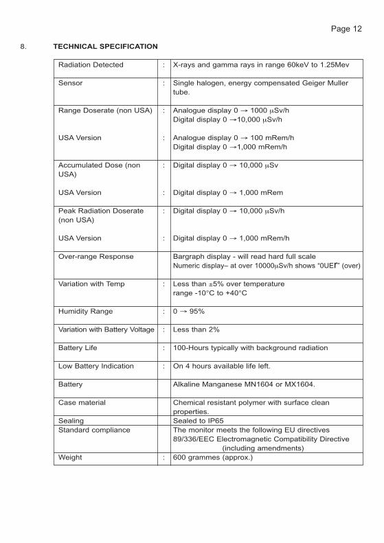
8. TECHNICAL SPECIFICATION
Radiation Detected : X-rays and gamma rays in range 60keV to 1.25Mev
Sensor : Single halogen, energy compensated Geiger Muller tube.
Range Doserate (non USA) : Analogue display 0 → 1000 μSv/hDigital display 0 →10,000 μSv/h
USA Version : Analogue display 0 → 100 mRem/hDigital display 0 →1,000 mRem/h
Accumulated Dose (non : Digital display 0 → 10,000 μSvUSA)
USA Version : Digital display 0 → 1,000 mRem
Peak Radiation Doserate : Digital display 0 → 10,000 μSv/h(non USA)
USA Version : Digital display 0 → 1,000 mRem/h
Over-range Response Bargraph display - will read hard full scaleNumeric display– at over 10000μSv/h shows “0UEr” (over)
Variation with Temp : Less than ±5% over temperature range -10°C to +40°C
Humidity Range : 0 → 95%
Variation with Battery Voltage : Less than 2%
Battery Life : 100-Hours typically with background radiation
Low Battery Indication : On 4 hours available life left.
Battery Alkaline Manganese MN1604 or MX1604.
Case material Chemical resistant polymer with surface clean properties.
Sealing Sealed to IP65Standard compliance The monitor meets the following EU directives
89/336/EEC Electromagnetic Compatibility Directive(including amendments)
Weight : 600 grammes (approx.)
Page 12

8.1 Additional Information on Monitor Calibration
Tests involving the response of the T402 monitor to radiation doserate have been carriedout using a specially designed calibration rig which allows the instrument to be exposedto a range of radiation dose equivalent rates by precisely varying the distance from twoindependent Caesium-137 sources.
The accuracy of the calibration facility has been independently checked and shown thatthe Ambient Dose Equivalent Rate deviation from 1/r2 is less than 5% relative for thesources of Caesium-137 and Americium-241.
9. HINTS FOR RADIATION DOSERATE MONITORING
� Ensure audible output is selected when monitoring “radiologically unknown”environments. Minimises potential for exposure if attention is diverted from themonitor screen and provides an audible warning to other workers in the locality.
� Radiation detector is located parallel to the head of the monitor (approximatelybelow the position of the Tracerco logo). For maximum accuracy and sensitivitypoint this face directly at the suspected source of radiation.
� Remember time and distance rules to minimise personal exposure. Theaccumulated dose and peak doserate options should reinforce safe workingpractices.
� Hold the monitor at a comfortable distance in front of the body. This approachmaximises the response time to allow minimisation of the whole body dose.
� Wherever possible, check that the monitor is working before use by placing it inthe vicinity of a known test source. Alternatively, ensure that sensiblebackground radiation doserate values are being displayed.
10. WARRANTY
It would be expected that under prescribed usage the T402 monitor should give years ofreliable operation. If, however, any fault arises with the monitor within twelve months ofpurchase and Tracerco can reasonably attribute this to a manufacturing defect, Tracercowill repair or replace the monitor free of charge.
If a fault occurs outside of the warranty period or if the monitor suffers damage as a resultof an accident or inappropriate usage, Tracerco is able to provide a rapid repair service(usually within 7-days of receipt).
Page 13

It is recommended that if the customer considers that there is a problem with the monitor,they should, in the first instance, contact our customer service helpline at the followingaddress:-
Customer Services HelplineTracer Technology Centre (Monitor Dept) Pavilion 10 The Moat Belasis Hall Technology Park Billingham Cleveland TS23 4AZ. Tel : +44 (0)1642 375450 Fax : +44 (0)1642 371813E-Mail : [email protected]
Please note that Tracerco cannot accept liability for any loss or damage during shippingand the customer should ensure that the instrument is suitably packaged.
11. HEALTH & SAFETY
The T402 Radiation Doserate Monitor has been extensively tested for accuracy andreliability in a designated application. Tracerco considers that it has taken all reasonableprecautions to ensure that when used as prescribed, the monitor will not endanger thehealth and safety of the operator. It is important, however, that the following basicguidance should be taken into account by the operator when carrying out any form ofradiation doserate monitoring.
1. Operators should receive appropriate practical training in the use of radiationdoserate monitors.
2. Battery life should be checked before use, particularly where extended workprogrammes are to be carried out in particularly difficult to access locations.
3. The monitor has been designed and tested to EN60846:2004 to ensure that ifthe monitor is exposed to radiation levels well in excess of the full scale values(ie., up to 100 times), the readings will recover and normal operation resumedonce the source of radiation has been removed. The digital numeric scale willread “OVER” when maxima values have been exceeded and the bargraph meterwill sustain full scale deflection.
The operator should never attempt to estimate a reading when over-range hasoccurred.
4. The monitor meets EN60846:2004 standard requirements for directionalresponse. It is recommended that in normal use, the monitor is held with thescale horizontal and the audible response is operational. The operator shouldalways be aware that exposure shine paths may exist where there is a markedvariation in radiation doserates in both horizontal and vertical planes. It isstrongly recommended that all operators receive adequate training for the typeof radiation monitoring to be carried out.
Page 14

5. In the event of a Geiger Muller tube failure an “ERR1” message will appear onthe screen. In circumstances where the tube receives negligible backgroundsignal over a continuous counting period of 20 seconds, (and the tube remainsoperable), the monitor will display a “lo BGnd” message. If the monitor isexposed to a positive count rate the message will disappear and normaloperation resumed.
Practical pointsThe preferred batteries are Duracell MX1604 Alkaline manganese
OrMN1604 Alkaline manganese
Lock the battery compartment by the screw in the compartment lid. Do not over tighten.Do not use solvents on the monitor window.
Page 15

Tracer Technology CentrePavilion 10, The MoatBelasis Hall Technology ParkBillinghamCleveland TS23 4AZUKTel +44 (0)1642 375450Fax +44 (0)1642 371813
Chattan Mews Office18 Chattan Place AberdeenAB10 6RDUKTel +44 (0)1224 592527Fax +44 (0)1224 212641
Tracerco4106 New West DrivePasadenaTX 77507USATel: 281-291-7769Fax: 281-291-7709Toll Free: 1-800-288-8970
Tracerco Asia708 Block GPhileo Damansara 1No 9 Jalan 16/11 46350Petaling JayaSelangor MalaysiaTel: +603 7957 9821Fax: +603 7955 2821
www.tracerco.com tracerco�matthey.com
A Member of the Johnson Matthey Group
?????/?/?
TRACERCO and TRACERCO Diagnostics are trademarks of the Johnson Matthey Group of companies.