track construction and maintenance field guide · practice information that is useful when carrying...
TRANSCRIPT
1
TRACK CONSTRUCTION AND MAINTENANCE
FIELD GUIDE
JULY 2008

2
PurposeThis field guide provides advice and technical information for staff in the field, on the construction and maintenance of recreation tracks for walkers and off road mountain bikers. It has been derived from the Track Construction and Maintenance Guidelines. The aim of the field guide is to provide best practice information that is useful when carrying out track work. However, best practice will often be dependent upon local materials, climate, equipment and costs.
ScopeMuch of the guide is devoted to management of formed, benched tracks, but it has to be borne in mind that most tracks managed by DOC are not constructed and benched and do not have to be.The field guide will not provide information on archaeological sites, organic wetlands, sand dunes or areas with sensitive tree root plates. Many of these locations require specific solutions for which suitable advice should be sought.
Published by:Department of ConservationResearch and Development GroupHead OfficeWellington
July 2008
ISBN 978-0-478-14444-4
© Department of Conservation

3
Contents
Section 1: Construction Principles and Soils --------------------4
1.0 Guiding principles for track construction ----4
2.0 Soil types ------------------------------------------------5
Section 2: Track Construction ----------------------------------------8
3.0 Track construction ------------------------------------8
4.0 Track gradient ------------------------------------------8
5.0 Field Survey --------------------------------------------9
6.0 Track formation -------------------------------------- 13
7.0 Water management -------------------------------- 21
8.0 Track pavement ------------------------------------- 37
9.0 Track compaction ----------------------------------- 43
10.0 Geotextiles -------------------------------------------- 48
11.0 Step construction techniques ----------------- 50
12.0 Turns ---------------------------------------------------- 56
13.0 Retaining walls--------------------------------------- 60
Section 3: Track Maintenance -------------------------------------- 66
14.0 Sustainable maintenance ------------------------ 66
15.0 Track marking ---------------------------------------- 67
16.0 Vegetation maintenance -------------------------- 71
17.0 Drainage system maintenance ----------------- 74
18.0 Geotextiles maintenance ------------------------- 76
19.0 Stone pitching maintenance -------------------- 77
20.0 Track surface maintenance ---------------------- 77
21.0 Slough and berm ----------------------------------- 79
22.0 Steps maintenance --------------------------------- 80
23.0 Switchbacks maintenance ----------------------- 80
Appendix: slope inclinometer --------------------------------------- 81

Construction Principles and Soils4
Section 1: Construction Principles and Soils
1.0 Guiding principles for track construction
Keep water away from the track surfaceMaintain a cross fall of between 1 – 2º (3 – 4%) and maintain track shape. Remove water from the side of the track as soon as possible using a suitable water drainage system. Maintain natural waterways.
Construct sustainable gradesGenerally speaking, the lower the grade the more sustainable the track will be over the long term.
Make the track flowAvoid straight lines, follow the natural contour, make the track flow through the land.
Provide a suitable walking surfaceApply metal aggregate only where necessary. Where engineering techniques are required build on a firm foundation, ensure adequate pavement depth. Make use of suitable local materials and compact at the correct moisture content.
Maintain a good surfaceWhere necessary, establish a good track surface that binds together, replace lost material and maintain track shape.
Maintain when requiredMaintain to the correct standard.
Be environmentally astuteTake into account any environmental impacts caused by track work. In particular pay attention to poor maintenance practices and inadequate drainage which could cause sediment and erosion issues.
Protect the investmentFollow the ongoing inspection regime. It is there to help protect your tracks.
Train staffEnsure staff are well trained and kept up to date with current best practice.
Respect and keep historic valuesWhere the track has distinctive historic values, ensure that character is maintained.

5Soils
2.0 Soil types
Soil particle size is the most important factor to indicate the likely behaviour and performance of a track. The long-term performance of any construction project depends on the soundness of the underlying soils. Unsuitable soils can create significant problems for tracks. Soil is characterised by its structure which in turn is determined by particle size. There are four generic soil types based on particle size: clay, silt, sand, and gravels. Each one is different in size and shape and affects how a track will perform under certain conditions. The proportions of clay, silt, sand and gravel determine its ability to resist deformation and erosion. Being able to discern which type you are dealing with will aid your track work. The key issue for design and construction purposes is whether the soil will act as a cohesive or granular material.
Fine Earth Fragments
Rock Earth Fragments
Type Term
Boulders > 200mm
COARSE
GRANULAR
Cobbles 200-60.0mm
Gravel 60mm-2.0mm
Coarse sand 2.0 – 0.6mm
Medium sand 0.6 – 0.2mm
Fine sand 0.2 – 0.06mm
Silt 0.06 – 0.002mm FINE
COHESIVE
Clay < 0.002mm
Granular soil is where all the particles are larger than silt size and a cohesive soil is where all the particles are smaller than sand. Soils containing a full range of particle sizes from clays to gravel will act cohesively if only 15% to 25% of the particles are clay or silt sized.
Table 1: Soil categories

Construction Principles and Soils6
2.1 Field testsThere are some simple tests which determine one soil type from another.
2.1.1 Clay soilTo determine the plasticity of clay in the field, mould the shape of the sample over a range of moisture contents.
Moist clay sticks, easily forms into a ball and leaves a stain in ♦the palm of your hand.Dry clay is very hard and almost impossible to break with your ♦hand (if it is highly plastic).
2.1.2 Silty soilTo distinguish between silts and clay soils, place a handful of soil (sufficiently wet to be almost sticky) in your open palm. Tap the bottom of the hand with the other hand. If the sample is a silt, water will appear on the surface, giving it a shiny appearance and will then disappear if the sample is squeezed or manipulated. When it is manipulated the sample tends to dilate and draw water back into it. With clay, these characteristics are not present.
Moist silt feels smooth and sticky but falls apart. Does not leave ♦much of a stain on your hand.Dry silt feels like flour, smooth and powdery. ♦
2.1.3 Sandy soilMoist sand when squeezed together in the palm of your hand ♦will form a ball which will break apart easily and not leave a stain on your hand.Dry sand feels rough and will not hold together. You can see ♦individual particles of sand.
2.1.4 Loam soilLoam soils are a combination of all three particle types, without a dominant type. Generally loam soils are good to work with, they have reasonable drainage and hold together well.
Wet loam forms a ball when squeezed together in the palm of ♦your hand. It is neither too gritty or sticky.
All leaf litter and organic matter (peat, topsoil) should be removed from the cut and fill zone. Avoid building a track on this material as its organic content makes it unstable. Save it to rehabilitate borrow pits and to help reduce the impact of construction work.

7Soils
Table 2: Soil properties and behaviour relevant to track construction
Property Silt Sand Clay
Water holding capacity
low medium to high high
Drainage high slow to medium very slow
Compaction low medium high
Susceptible to water erosion
low high low (if aggregated)high (if not)
Some soils are unsuitable as a walking surface. Table 3 outlines suitable and unsuitable types.
Table 3: Suitability of soil types as track foundation
Not suitable as track foundation
Suitable with the use of a geotextile
separator
Suitable foundation
Organic humus Peat Firm clay / soils
Soft clay / silt soils Sands / gravels
Rocks
Nearly all track surfaces sink from compaction, including well ♦constructed and compacted surfaces.The centre and inside of corners become most compacted as this ♦is where most activity takes place, outer edges will generally be less compacted.Non-compacted sideslope tracks often fail because the centre has ♦been compacted. The more susceptible the surface to compaction the faster the rate of compaction and the sooner outslope failure will occur.Compaction makes the surface more resistant to erosion and displacement. ♦Water finds it difficult to go through a compacted surface causing ♦more water to run off the track; so water management becomes even more important.

8 Track Construction
Section 2: Track Construction
3.0 Track construction principles
To build or upgrade a track you need to adopt the hot tips listed below. Adopting only some will not give you a truly great track. Adopt and implement them all and your track will last.
HOT TIPS
If using benched tracks cut across the face of a hill
Stick to the half rule as much as possible
Avoid the fall line
Follow the 6º(10%) average guideline
Keep below the maximum sustainable grade
Install regular grade dips
Plan your track shape
Design according to soil type
Minimise soil displacement caused by users
Prevent shortcuts
Maintenance, maintenance, maintenance
4.0 Track gradient
Gradient refers to the longitudinal steepness of the track and slope refers to the steepness of the ground on the fall line. Gradient and slope are expressed as degrees (6º) or percentages (10%) or a ratio of vertical to horizontal distance expressed as single ratios (1:10). The tool most commonly used to measure grade today is the slope inclinometer. The appendix explains how to check the accuracy of an inclinometer and how to use one.

9Field survey
HOT TIPS
Keep track gradient to the minimum practical for the site.
Lower track gradients require less maintenance. Gravity and water will move fewer soil particles and visitors will displace less material.
5.0 Field survey5.1 Initial field survey
There are a number of good reasons to do an initial reconnaissance, including to:
Determine whether it is physically possible to construct and ♦maintain the track.Spend time getting to know the terrain so you don’t miss the ♦best alignment.Verify the strategic locations and identify any further points the ♦track should visit that were not apparent on the map, e.g., good lookout points, small flat areas for switchbacks, areas of interest.Identify areas that will need to be avoided – grade could be ♦too steep or there may be erosion prone soils.Peg out the proposed alignment. ♦
Degrees Percentage Rise to run
1 1.7 1 in 57.3
2 3.5 1 in 28.6
3 5.3 1 in 19.1
4 7.0 1 in 14.3
5 8.7 1 in 11.4
6 10.5 1 in 10.5
7 12.3 1 in 8.2
8 14.0 1 in 7.1
9 15.8 1 in 6.3
10 17.6 1 in 5.7
11 19.4 1 in 5.1
12 21.3 1 in 4.7
13 23.1 1 in 4.3
Table 4: Approximate gradient comparisons
Degrees Percentage Rise to run
14 25.0 1 in 4
15 26.8 1 in 3.7
16 28.7 1 in 3.5
17 30.6 1 in 3.3
18 32.5 1 in 3.1
19 34.4 1 in 2.9
20 36.4 1 in 2.7
21 38.4 1 in 2.6
22 40.4 1 in 2.5
23 42.5 1 in 2.4
24 44.5 1 in 2.2
25 46.6 1 in 2.1
10 Track Construction
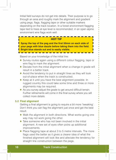
Initial field surveys do not get into details. Their purpose is to go through an area and roughly mark the alignment and gradient using pegs, flags, flagging tape or other suitable markers depending on the track location. In a forest environment flagging tape tied to trees at eye level is recommended; in an open alpine environment wire flags work well.
HOT TIP
Spray the top of the peg and the first 50mm on each side of your pegs with blue dazzle before taking them into the field. Bright blue stands out and is easily visible.
Based on your knowledge of the initial line:Survey routes again using a different colour flagging, tape or ♦wire flag to mark the alignment.Deviate from the initial alignment when a change in grade will ♦result in a better track.Avoid the tendency to put in straight lines as they will look ♦out-of-place when the track is constructed.Keep at it until you have the best alignment possible. In ♦rugged country this could take some time and three or more alignments may be required.As you survey adjust the grade to get around difficult terrain. ♦Further refinements will come in the final survey where you will collect more details.
5.2 Final alignmentGetting a final alignment is going to require a bit more ‘tweaking’. Don’t think you can flag the alignment just once and get the best result.
Walk the alignment in both directions. What works going one ♦way may not work going the other.Take someone who has not been involved in the initial ♦alignment. A new set of eyes often picks up additional improvements.Place flagging tape at about 3 to 5 metre intervals. The more ♦flags used the better as it gives a clearer idea of what the finished alignment will look like and alleviate the tendency for straight line construction between the pegs.
11Field survey
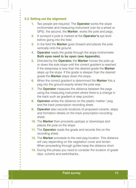
5.3 Setting out the alignment
Two people are required. The 1. Operator works the slope inclinometer and measuring instrument (can be a wheel or GPS); the second, the Marker, works the pole and pegs. A surveyor’s pole is marked at the 2. Operator’s eye level before going into the field.In the field the 3. Marker goes forward and places the pole vertically onto the ground.Operator4. reads the grade through the slope inclinometer. Both eyes need to be open (see Appendix).Directed by the 5. Operator, the Marker moves the pole up or down the side slope until the correct gradient is reached. If the steepness is less than the desired grade the Marker steps up the slope. If the grade is steeper than the desired grade the Marker steps down the slope.When the correct gradient is determined the 6. Marker hits a peg into the ground exactly where the pole was.The 7. Operator measures the distance between the pegs using the measuring instrument where there is a change in the track such as gradient or step junction.Operator8. writes the distance on the plastic marker / peg and the track prescription recording sheet.Operator9. also records locations of proposed culverts, steps and formation details on the track prescription recording sheet.The 10. Marker then proceeds upslope or downslope and places the pole on the slope.The 11. Operator reads the grade and records this on the recording sheet.The 12. Marker proceeds to the next peg location. This distance will vary depending on the vegetation cover and terrain. When proceeding through gullies keep the distance short.During this phase you need to consider the location of grade 13. dips, culverts and switchbacks.

12 Track Construction
HOT TIPS
Survey the whole track and be sure you have the best possible alignment before construction work starts.
Bring in a ‘fresh set of eyes’ to look at the alignment.
Mark the area within which construction is permitted. This minimises impacts on the landscape and helps with the ‘fit’ / look.
Visit the site during or shortly after extended periods of rain to identify drainage requirements.
Cross streams at an angle rather than going straight down and up the other side.
Look for natural platforms for switchbacks; saves construction costs and provides a better ‘fit’ with the landscape.
Identify locations for grade dips.
If you are a person who must guess the grade using your eye, always check it with your slope inclinometer as well.
Keep in mind the visitor type the track is for and try to put yourself in their shoes as you plan it.

13Formation
Figure 2 – Outslope track formation
Figure 1: Crown track formation
6.0 Track formation
There are three track construction shapes; crown, outslope and inslope. To decide which track shape to adopt think about long term sustainability. Some soil types are more erosion prone than others. Alignment, grade and drainage also have a significant impact on track erosion.A crowned track has a side drain on its upslope side to catch water and help protect the track pavement. ‘Pavement’ is a collective term for the combined layers that form protection of the sub-grade. Crowned tracks are most suitable where the track gradient exceeds 3º – 4º (5% – 7%) and water runoff is moderate to high.
Figure 2: Outslope track formation

14 Track Construction
Figure 3: Inslope track formation
An inslope or outslope track allows water to flow across the track surface and is best suited to locations where the track gradient is 4º (7%) or less and there is low water runoff. The maximum gradient recommended for an inslope or outslope track is 6° (10%). Depending on how erosion prone the soil is, application of stone aggregate may also be required. Whichever track shape you decide to construct it will need to have a crossfall of approximately 2º (3 – 4%).
6.1 Cut constructionCut construction involves excavation, cutting into the ground to remove soil and relocating it where you want it. This results in a bench or flat surface that becomes the walking track. A full cut bench track involves cutting to the full width of the track surface. Full bench cuts:
Are ♦ necessary when sideslopes are over 25º (50%).Require ♦ less maintenance on this slope.Should ♦ have the top of the batter rounded, 200 mm either side of the high point, as close as possible to the original slope.Generally provide surplus material. This can be relocated and ♦used as fill elsewhere on the track to even out gradients.Should ♦ have exposed roots on the cut batter neatly trimmed flush with the batter face.

15Formation
6.2 Cut and fill constructionCut and fill construction involves cutting into the uphill sideslope and placing fill on the downhill slope. Cut and fill formation results in a bench finish. An advantage of implementing the cut and fill technique is that the volume of material moved is less and the size of the inside batter is lower in height creating a lower visual impact.
Cut and fill when used on sideslopes between 17º – 25º (31 – 47%)Construction only works where the sideslope is less than the ♦maximum fill batter slope for the soil, as specified in Table 7.Fill on the downslope is placed on a small bench measuring ♦300 mm that is sloped into the hill, then slightly compacted in layers to form a stable surface.All fill material needs to be compacted in layers no greater ♦than 250 mm prior to compaction.Should be constructed with a ¾ bench and ¼ fill as the ♦track walking surface. Save organic material (leaf litter or any topsoil); use it to spread ♦over the fill to make the track look as though it has been there for some time.Top of the batter should be rounded 200 mm either side of the ♦high point, as close as possible to the original slope.Exposed roots on the cut batter should be neatly trimmed flush ♦with the batter face.
Cut and fill when used on sideslopes between 6º–17º (10–31%)Half bench and half fill. ♦Save organic material (leaf litter or any topsoil); use it to spread ♦over the fill to give the track an aged look.A small, 300 mm bench will need to be cut ♦ downslope to provide a flat platform for the fill material.Fill slope should be a maximum as specified in ♦ Table 7.All fill material needs to be in layers no greater than 250 mm ♦prior to compaction.The batter should be rounded 200 mm either side of the high ♦point, as close as possible to the original slope.Exposed roots on the cut batter should be neatly trimmed flush ♦with the batter face.

16 Track Construction
6.3 Fill construction‘Fill construction’ is use of material placed on site to form a walking track. No bench is associated with this construction. Refer to Table 7 for maximum fill batter slopes.
6.4 Cut and fill material
Table 5: Soil types for track construction
Suitable for use as fill material Not suitable for use as fill material
Firm clay / silt soils* Peat / organic humus
Sands / gravels Topsoil
Boulder clay Soft clay / silt soils
Weathered rock
*Highly plastic soils (discussed in section 2.1) can be used if permitted to dry out as they become very hard.
HOT TIPS
Excavated rock fill will occupy 1.2—1.5 times more space than solid rock.
Excavated soil will expand when loaded for transport by 1.2—1.7 times.
Excavated soil when compacted can shrink by 0.6—0.8 times the original volume depending on the soil type.
! PITFALLIf you do not compact the fill you will get regular slumps
on the track over an extended period.
17Formation
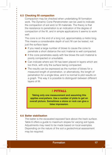
6.6 Batter stabilisationThe batter is the excavated exposed face above the track surface. Table 6 offers a guide to maximum slopes for varying soil types. Adjustments may need to be made based on local examples. Depending on the nature of the soil a geotechnical assessment may be required.
6.5 Checking fill compactionCompaction may be checked when undertaking fill formation work. The Dynamic Cone Penetrometer can be used to indicate the compaction of soil and / or fill materials. The theory is that the resistance to penetration is an indication of the degree of compaction of the fill, and in simple applications it seems to work well. The cone is on the end of a long rod, approximately a metre long. This means a considerable depth of soil / fill can be tested, not just the surface layer.
If you need a large number of blows to cause the cone to ♦penetrate a short distance the soil / material is well compacted.If the cone penetrates easily with few blows the soil / material is ♦poorly compacted or unsuitable.Can indicate where soil / fill has been placed in layers which are ♦too thick, with only the surface being compacted.The results can be expressed as the number of blows for a ♦measured length of penetration, or alternatively, the length of penetration for a single blow, and it is normal to plot results on a graph. This way it is possible to distinguish between different layers of fill.
! PITFALLTaking only one measurement and assuming this
applies everywhere. Use a number of plots to get an overall picture. Sometimes a stone or rock can give a
false impression.
18 Track Construction
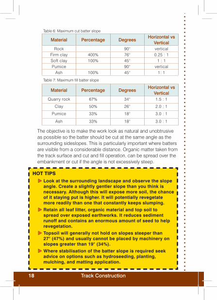
Table 6: Maximum cut batter slope
Material Percentage DegreesHorizontal vs
VerticalRock 90° vertical
Firm clay 400% 76° 0.25 : 1Soft clay 100% 45° 1 : 1Pumice 90° vertical
Ash 100% 45° 1: 1
Table 7: Maximum fill batter slope
Material Percentage DegreesHorizontal vs
VerticalQuarry rock 67% 34° 1.5 : 1
Clay 50% 26° 2.0 : 1
Pumice 33% 18° 3.0 : 1
Ash 33% 18° 3.0 : 1
The objective is to make the work look as natural and unobtrusive as possible so the batter should be cut at the same angle as the surrounding sideslopes. This is particularly important where batters are visible from a considerable distance. Organic matter taken from the track surface and cut and fill operation, can be spread over the embankment or cut if the angle is not excessively steep.
HOT TIPS
Look at the surrounding landscape and observe the slope angle. Create a slightly gentler slope than you think is necessary. Although this will expose more soil, the chance of it staying put is higher. It will potentially revegetate more readily than one that constantly keeps slumping.
Retain all leaf litter, organic material and top soil to spread over exposed earthworks. It reduces sediment runoff and contains an enormous amount of seed to help revegetation.
Topsoil will generally not hold on slopes steeper than 27° (47%) and usually cannot be placed by machinery on slopes greater than 19° (34%).
Where stabilisation of the batter slope is required seek advice on options such as hydroseeding, planting, mulching, and matting application.

19Formation
Figure 4 – Acceptable borrow pit location
6.7 Use of local materialsExtra fill is often sourced on site. Borrow pits are a hole dug in the ground from which material is removed and used on the track. Even on a minor scale moving material from one location can cause changes to the environment which need to be managed.Potential adverse effects of borrow pits can be reduced or avoided by choosing the site carefully (Figure 4). Good planning will help to minimise any potential adverse effects. Guidelines that need to be followed if using a borrow pit:
Locate pit to minimise visual exposure to users. ♦Ensure the site is made safe. ♦Save the vegetation and top soil layers for rehabilitation of the ♦site. Place them in the shade and keep them moist. Cover with burlap (type of sacking), to help keep moist if necessary. Ensure material from the borrow pit is suitable for the intended ♦use.Create a long shallow pit rather than a deep one. ♦Reinstate all drainage patterns. ♦Contour the ground to look as natural as possible when ♦finished removing material and ensuring it is stable.Replace vegetation and top soil layers. If necessary transplant ♦additional plants onto the site.Camouflage any entrance track — transfer some plants if ♦necessary. Be particularly diligent where the entrance track meets the main walking track.
20 Track Construction
6.8 Formation constructionComplete all alignment work with pegs clearly marked at the ♦level of formation.
Ensure the work site area is clearly marked. Disturbance can ♦only take place within the marked area.
Remove all leaf litter and organic material and store in a ♦suitable location for later use.
Where it is not practical to remove all organic material, ♦use of a geotextile separator may be required (see section 10.1). Some settlement may occur as the organic material underneath the track decomposes.
Excavate and relocate material to achieve the formation and ♦gradient specified. Relocation of material can help even out some grades, i.e., as cover over tree roots, or fill for steps and retaining walls. Surplus material should not be sidecast.
Fill material needs to be compacted in layers no greater ♦than 250 mm (prior to compaction).
Install water management, including side drains and drainage ♦dips etc, as formation takes place or at the end of each day. Never leave a new formation without water management.
Shape and compact the formation surface (crown, outslope ♦or inslope). This is necessary even if the completed formation is the finished track surface. An uncompacted surface will quickly become concave. Strengthening the sub-grade, the soil the pavement structure is constructed upon, is good practice as it helps maintain track shape.
Mark the formed surface at the correct distance in preparation ♦for aggregate.
Shape and compact aggregate as covered in section ♦9.0—9.4.
21Water management
7.0 Water management
Walk the full length of the track in both directions, sometimes a water issue near the top can be causing additional problems further down the track.
LOOK FOR CLUES
Small gullies and erosion channels in the track surface — water flowing down or across the track.
Puddles, boggy areas — water lying on the track.
Water flowing onto the track from sideslope — where has this come from?
Build up of fines, clay, silt and very fine sand, either on the track or just to the side — shows where the water has gone.
Some vegetation types can indicate wet ground conditions.
7.1 Water control methodsThere are a number of methods used either individually or combined together to manage water; grade dips (rolling dips, drainage dips, grade reversals) catch drains, side drains, catch pits, pipe culverts and drainage channels.
7.2 Grade dipsGrade dip locations are determined during the 'setting out stage' (Section 5.0) and built during the track formation. Grade dips are used to remove track surface water at intervals, along tracks of a minor to moderate grade, located on a sideslope. Dips are built into the track at intervals dictated by the erodibility of the track surface and the track gradient. Grade dips are a very cost effective method of managing water. They require less maintenance than a culvert and are much more effective at removing water than a waterbar and require less maintenance. (A waterbar is an obstruction to the flow of water installed across the track at an angle).

22 Track Construction
7.2.1 Rolling grade dipA rolling grade dip is where you reverse the gradient of the track over a short distance. For example, if the track is ascending a hill at 4º (7%) a short descent of between 3 – 5 metres at 2º (3.5%), followed by returning to the ascent of 4º (7%) would form a rolling grade dip.A track that lies lightly on the land will have a number of rolling grade dips and a well designed track will take advantage of the natural drainage patterns. Tracks designed in this way look good, feel right and 'fit' the landscape.
7.2.2 Drainage grade dipA drainage grade dip is a relatively large dip constructed into the track surface to shed water from the track. Drainage grade dips are very unobtrusive and constructed properly are barely noticeable but very effective at water management. In the majority of circumstances they can be constructed on existing tracks.
Figure 5: Drainage grade dip for outslope track

23Water management
Figure 6: Drainage grade dip for crowned track
Recommended drainage grade dip spacings are outlined in Table 8. However, this won’t always be practical and will be influenced by the alignment of the track. Critical points to locate a drainage dip are:
prior to a flight of steps prior to retaining walls just above the point where the track changes grade and becomes steeper.
Actual site conditions determine exact placement. It is important not to exceed the spacing outlined in Table 8. Where the recommended distance does not fit with the track alignment add an extra dip rather than take one away.

24 Track Construction
Table 9: Drainage dip grade dimensions
Track Grade
degrees
Track Grade
percent
Backing length for backwall
(mm)
Length of backwall
(mm)
Depth of dip* (mm)
Length of ramp
(mm)
Totallength(mm )
1% N / A 1575 75 1950 3525
1º 2% 200 1525 75 2300 4025
2º 3% 300 1500 100 2600 4400
4% 400 1425 100 2900 4725
3º 5% 500 1375 100 3250 5125
6% 600 1325 100 3500 5425
7% 650 1300 125 3900 6150
4º 8% 725 1250 125 4200 6175
* depth of the dip is measured from the top of the finished backwall to the bottom of the dip.
7.2.3 Drainage grade dip construction for outslope trackOn the track surface, mark the start and end points of the ♦drainage dip. This will vary depending on the track grade as specified in Table 9.From each mark, from the top edge of the track scuff a line on ♦the track surface. This line should be down the gradient and across the track at an angle of between 15° – 20°.From the top of the ramp measure the distance to the dip low ♦point and mark the track surface.
Track Grade degrees
Track Grade percent Rise to run ratio
Distance between Drainage Grade Dips (metres)
1° 1.7% 1:57 272° 3.5% 1:28 173° 5.3% 1;19 144° 7.0% 1:14 135° 8.7% 1:11 126° 10.5% 1:10 117° 12.3% 1:8 118° 14% 1:7 109° 15.8% 1:6 10
10° 17.5% 1:6 10
NB: The distance between Drainage Grade Dips is from the end of the backwall to the beginning of the ramp on the next dip.
Table 8: Recommended drainage grade dip spacing

25Water management
Scuff another line on the track surface. This line should be down ♦the gradient and across the track at an angle of between 15°– 20°.Dig the dip low point line down to the depth specified in ♦ Table 9. Excavate the material from the start of the ramp and backwall ♦to the dip low point.Create an even and nicely contoured finish. ♦Make sure the outflow point is clear and water can flow down ♦the sideslope.Compact dip if compactor is available. This will ♦strengthen the dip and reduce potential scour.
7.2.4 Grade breakGrade breaks can be used in place of drainage dips on tracks of 2°(3.5%) or less.
Grade brakes cannot handle much water and are better suited ♦to low use, low runoff locations.Grade breaks need to be installed every six metres. ♦
Figure 7: Grade Break Profile

26 Track Construction
7.3 Catch drainsA catch drain is located some distance from the track. It catches water before it reaches the track and redirects it. It can be:
A swale; wide and shallow depression in the ground designed ♦to channel drainage of rainwater.A bund; an embankment formed from natural material. ♦A ditch; long narrow open channel dug into the ground ♦
7.3.1 Catch drain constructionThe positioning of catch drains is essential to the success of ♦the drainage system.Maintain a low visual impact on the landscape. ♦Ensure there are no adverse effects on the natural land drainage. ♦Keep the gradient low so the ditch does not scour. It can be at ♦a much flatter gradient than the track.Excavate the catch drain to a depth of 300 mm x 300 mm wide. ♦Place excavated material on the downhill side of the ditch. It ♦acts as a bund if the catch drain overflows and prevents water flowing onto the track.
HOT TIPSFollow the lie of the land. Avoid steep gradients. Start construction at the bottom and work uphill as this makes it easier to keep the depth consistent.Avoid sharp corners or direction changes that will erode the drain. Maintain catch drain effectively.
Grade break constructionOn the track surface, mark the location of the shelf and low ♦point of the grade break.Distance from the shelf to the bottom of the dip is 1.5 metres. ♦From each mark, from the top edge of the track scuff a line ♦directly across the track surface.Dig the dip low point line down to a depth of 25 mm. ♦Excavate the material between the shelf and low point. ♦Create an even and nicely contoured finish. ♦Make sure the outflow point is clear so water can flow down the ♦sideslope.Compact grade break. This strengthens the break and reduces ♦potential scour.

27Water management
Soi
l ty
pe
Hig
h ra
infa
ll ar
eas
Med
ium
rai
nfal
l are
as
Dis
char
ge
Sp
acin
gA
rmo
uri
ng
Dis
char
ge
Sp
acin
gA
rmo
uri
ng
Sof
t cla
y,
ash
Fo
r g
rad
ient
< 6
° (1
0%),
• 15
m m
axi
mum
sp
acin
g
Fo
r g
rad
ient
up
to 1
0°
• (1
7%),
10
m s
pac
ing
Gra
die
nts
over
10°
(17
%)
• no
t rec
om
men
ded
Pro
vid
e ro
ck o
r g
rave
l •
whe
re g
rad
ient
exc
eed
s 17
% o
r w
here
dis
char
ge
spac
ing
is m
ore
tha
n 15
m
Fo
r g
rad
ient
< 6
° (1
0%),
• 20
m m
axi
mum
sp
acin
gF
or
gra
die
nt u
p to
10°
•
(17%
), 1
5 m
sp
acin
gG
rad
ient
s ov
er 1
1° (
20%
) •
not r
eco
mm
end
ed
Pro
vid
e ro
ck o
r g
rave
l •
whe
re g
rad
ient
exc
eed
s 11
° (2
0%)
or
whe
re
dis
char
ge
spac
ing
is
mo
re t
han
20 m
Firm
cla
yF
or
gra
die
nt <
6°
(10%
), •
20 m
ma
xim
um s
pac
ing
Fo
r g
rad
ient
up
to 1
1°
• (2
0%),
15
m s
pac
ing
Gra
die
nts
over
11°
(20
%)
• no
t rec
om
men
ded
Pro
vid
e ro
ck o
r co
arse
•
gra
vel w
here
gra
die
nt
exce
eds
11°
(20%
) o
r w
here
dis
char
ge
spac
ing
is m
ore
tha
n 20
m
Fo
r g
rad
ient
<6°
(10
%),
• 25
m m
axi
mum
sp
acin
gF
or
gra
die
nt u
p to
11°
•
(20%
), 2
0 m
sp
acin
gG
rad
ient
s ov
er 1
1° (
20%
) •
not r
eco
mm
end
ed
Pro
vid
e ro
ck o
r co
arse
•
gra
vel w
here
gra
die
nt
exce
eds
11°
(20%
) o
r w
here
dis
char
ge
spac
ing
is m
ore
tha
n 25
m
7.4 Side drainsSide drains are constructed along the side of the track on slopes or on low wet ground where drainage is a problem.
Side drains ♦intercept water from the side slope and from the track surface watershed.
They carry the ♦water down to a discharge point (short cut-out, swale or excavated trench) or culvert that directs the water to the downslope side of the track.
Table 10 provides ♦recommended side drain armouring in relation to soil type and track gradient.
Tabl
e 10
: Sid
e dr
ain
arm
ourin
g in
rela
tion
to s
oil t
ype
Table 10 continues on page 28

28 Track Construction
Soi
l Ty
pe
Hig
h ra
infa
ll ar
eas
Med
ium
rai
nfal
l are
as
Dis
char
ge
Sp
acin
gA
rmo
uri
ng
Dis
char
ge
Sp
acin
gA
rmo
uri
ng
Pu
mic
e,
Wea
ther
ed
gra
nite
Fo
r g
rad
ient
<3°
(5%
), •
20 m
ma
xim
um s
pac
ing
Fo
r g
rad
ient
up
to 6
° •
(10%
), 1
5 m
sp
acin
gG
rad
ient
s ov
er 6
° (1
0%)
• sh
oul
d b
e av
oid
ed if
p
oss
ible
Pro
vid
e ro
ck, c
oar
se
• g
rave
l or
timb
er c
heck
d
ams
whe
re g
rad
ient
ex
ceed
s 6°
(10
%)
or
whe
re d
isch
arg
e sp
acin
g is
mo
re t
han
20 m
Fo
r g
rad
ient
<3°
(5%
), •
20 m
ma
xim
um s
pac
ing
Fo
r g
rad
ient
up
to
• 6°
(10%
), 1
5 m
sp
acin
gG
rad
ient
s ov
er 6
° (1
0%)
• sh
oul
d b
e av
oid
ed if
p
oss
ible
Pro
vid
e ro
ck, c
oar
se
• g
rave
l or
timb
er c
heck
d
ams
whe
re g
rad
ient
ex
ceed
s 6°
(10
%)
or
whe
re d
isch
arg
e sp
acin
g is
mo
re t
han
20 m
Fin
e g
rave
lsF
or
gra
die
nt <
6° (
10%
), •
25 m
ma
xim
um s
pac
ing
Fo
r g
rad
ient
up
to 1
1°
• (2
0%),
20m
sp
acin
gG
rad
ient
s ov
er 1
1°
• (2
0%)
not r
eco
mm
end
Pro
vid
e ro
ck o
r co
arse
•
gra
vel w
here
gra
die
nt
exce
eds
11°
(20%
) o
r w
here
dis
char
ge
spac
ing
is m
ore
tha
n 20
m
Fo
r g
rad
ient
<6°
(10
%),
• 30
m m
axi
mum
sp
acin
gF
or
gra
die
nt u
p to
11°
•
(20%
), 2
5 m
sp
acin
gG
rad
ient
s ov
er
• 11
° (2
0%)
not
reco
mm
end
ed
Pro
vid
e ro
ck o
r co
arse
•
gra
vel w
here
gra
die
nt
exce
eds
11°
(20%
) o
r w
here
dis
char
ge
spac
ing
is m
ore
tha
n 30
m
Co
arse
g
rave
l an
d
wea
ther
ed
rock
Fo
r g
rad
ient
<11
° (2
0%),
• 25
m m
axi
mum
sp
acin
gG
rad
ient
s ov
er
• 11
° (2
0%)
not
reco
mm
end
ed
Fo
r g
rad
ient
<11
° (2
0%),
• 30
m m
axi
mum
sp
acin
gG
rad
ient
s ov
er
• 11
° (2
0%)
not
reco
mm
end
ed
Gen
eral
not
es:
1. D
isch
arge
of s
ide
drai
ns m
ay b
e vi
a cu
lver
t, cu
t-out
, sw
ale
or s
oaka
ge p
it.
2. S
ide
drai
ns a
re b
est d
isch
arge
d im
med
iate
ly a
bove
ste
eper
sec
tions
of t
rack
.
3. S
ide
drai
ns w
ith s
teep
gra
dien
ts w
ill re
quire
incr
ease
d m
aint
enan
ce.

29Water management
7.4.1 Side drain construction Install side drains as follows:
Discharge water wherever the ground discharges to a lower ♦point away from the track. Short cut-outs or a small excavated swale or trench, may be required. A swale is the preferred option as it gives a visually softer appearance.Install culverts to take water under the track and discharge ♦to a lower point. See section 7.6.2 on recommended culvert frequency.If it is not possible to discharge water via a cut-out or culvert ♦the distance between discharge points will increase. To reduce scour, due to the increased volume of water, increase the size of the side drains and provide rock armouring. Rocks should be angular to lock together and minimise the likelihood of movement.Side drains should be a minimum of 200 mm wide by 150 mm ♦deep, chamfered to 250 mm wide at the top.Round square edges on side drains for aesthetic purposes. ♦Use excavated material on the track to form the ♦desired track shape. It will need to be compacted. Surplus material should not be discarded but used to even out grades or stored for maintenance purposes.
In erosion prone country side drains should be:constructed considerably deeper lined with geotextile filter fabric have loose local rocks (50 mm – 100 mm in size) placed to slow down the speed of the water.
HOT TIPS
During construction install water management options before proceeding to the next section. This reduces the risk of water damage over the newly formed track and newly formed batters.
Round side drain edges to produce a softer look rather than a sharp cut look.

30 Track Construction
7.5 Catch pitA catch pit (sometimes also referred to as a sump) is an excavated hole into which water from the side drain flows. Catch pits are usually located at the head of a culvert but can be constructed off the side of the track. Their purpose is to slow down the velocity of water and provide a point for sediment to be deposited. Reducing the speed of water that flows through the culvert also helps prevent erosion at the culvert outlet.
7.5.1 Catch pit construction at culvert pipesExcavate material at the culvert inlet. ♦Excavate to a ♦ minimum depth of 475 mm (150 mm culvert cover, 225 mm pipe and 100 mm invert). Larger culvert pipes will require a deeper catch pit.Excavate to a ♦ minimum width of 300 mm; the catch pit should be made wider rather than deeper.Catch pits should have square edges rounded for aesthetic ♦purposes. Use excavated material on the track and to form the ♦desired track shape. It will need to be compacted. Surplus material should not be discarded but used to even out grades or stored for maintenance purposes.Backwall, the down grade wall of the catch pit, ♦ should be 425 mm high (as opposed to 475 mm for the other walls), to act as an over flow into the next side drain. Surplus water can be discharged via a drainage grade dip for crowned tracks as shown in Figure 6 (p. 23) or via a larger culvert every third culvert.Protect the culvert headwall with rocks or timber. Rocks are the ♦preferred option if available. They should be embedded around the culvert mouth.
7.6 Pipe culvertsA pipe culvert is a closed pipe used to move water underneath impediments. This manual does not deal with the installation of culverts in intermittent or permanent water courses. They have specific requirements including consents and specific designs, e.g., installation of a fish passage. Refer to your planner and an engineer if you need to install a culvert in an intermittent or permanently flowing steam.

31Water management
7.6.1 Culvert sizeFor our purpose a culvert pipe takes water from one side of the track to the other. With the exception of those are required for permanent or intermittent water flows, culverts should meet the following requirements;
Recommended minimum culvert internal diameter is 225 mm. ♦Internal walls must have a smooth finish to allow material such ♦as leaves, small stones and twigs to pass through and reduce the likelihood of blockages.Black in colour. Bright coloured culverts create a visual impact. ♦
7.6.2 Culvert frequencyThe frequency of installed culverts depends upon the circumstances. Obviously it will be influenced by the soil, sideslope, local weather and track design. For high and medium rainfall areas refer to Table 10 for discharge recommendations. Table 11 provides recommendations on maximum culvert spacing for low rainfall areas.
Table 11: Recommended spacing between culverts for low rainfall areas
Degrees Percentage Rise to Run ratioMaximum distance between culverts
(metres)
3º 5.3% 1:19 50
6° 10% 1:10 25
8.5° 15% 1:7 18
10° 17% 1:6 16
11° 20% 1:5 14
17° 30% 1:3.3 10
7.6.3 Culvert installation specifications
Specifications for installing a 250 mm external diameter culvert pipe
Culvert external Diameter
Min trench width Min cover
Compacted pipe
bedding
Compacted pipe
overlay
Compacted depth of
fill / surface
250 mm 560 mm 150 mm 100 mm 75 mm 75 mm

32 Track Construction
7.6.4 Culvert installation
Work out how deep you need to dig the trench. It consists ♦of the compacted bedding layer (100 mm), plus the external diameter of pipe (250 mm), and minimum cover (150 mm) = 500 mm.
Excavate across the track at the required angle. ♦
Excavate the trench to the minimum width (560 mm) and depth ♦(500 mm) required.
Cut the pipe to the correct length, ♦ measure twice and cut once.
Allow the culvert to extend beyond the track formation without ♦risk of material blocking the drainage channel.
Level and compact the bedding material in the trench base with ♦a minimum fall of 1.7º (3.0%) to the outlet, working from the outfall end to the inlet. This maintains the required fall.
Place a smart level on the top of the culvert to ensure the fall is ♦correct, adjust the fall if necessary. Getting the fall absolutely right is important. Too flat and the culvert is likely to block, too steep and the outlet is likely to scour with the increased speed of exiting water.
Install the headwall base stones. ♦
Position the pipe and check alignment. ♦
Set base of culvert at the outlet at ground level. Avoid vertical ♦drops as a small waterfall may accelerate erosion.
Pack around the sides of the culvert with the bedding material ♦and compact in layers not exceeding 150 mm.
Continue to compact bedding material until culvert pipe is ♦covered by 75 mm.
Compact an additional 75 mm of pipe backfill comprised of the ♦walking surface material, shaped and compacted to the required finish. This gives a total of 150 mm cover over the pipe.
Set headwall side stones on the base stones, ensuring they ♦extend beyond the end of the culvert by 150 mm.
If possible use one top stone to span across to the side stones. ♦
33Water management
Wedge stones together using smaller ones packed tightly in ♦between to prevent movement. Hammer them into position with a rubber mallet.
Set splash stones above the base stone at the inlet and below ♦the base stone at the outflow.
Restore the site to as natural a condition as possible. For ♦visitors a well constructed culvert will not be visible.
HOT TIPS
Etch culvert all the way around before cutting.
Cut at least 300 mm wider than the width of the track. Buried at 300 mm as per specifications to allow for a batter of 1:1
Cut from the male end not the female end.
Cut with a handsaw.
Sandpaper or rasp every cut. This helps mainte- nance crews avoid cuts from the unfinished sharp edges.
Dazzle the ground, or mark it in some way, the angle the culvert will cross the track.
Use a smart level to check culvert fall.
Outlet should discharge at ground level.
Do not use culvert socks unless they can be made invisible to visitors.
! PITFALLSInsufficient fill over the top of the culvert
Poor headwall rock / timber work

34 Track Construction
7.7 Culvert headwall and outlet protectionDetermining soil scour potential and channel erodibility should be a standard component of track design.
Design the outfall on the basis that erosion at the outlet and ♦downstream channel is to be expected. Provide at least minimum protection, and then inspect the outlet channel after major storms to determine if the protection must be increased or extended.Line headwall with rocks, particularly around the culvert mouth. ♦Rocks lower excessive flow from pipes and culverts, prevent scour, and dissipate energy.Good outlet protection significantly reduces erosion and ♦sedimentation by reducing flow velocities.
HOT TIPS
Minimum fall of culvert pipe 1.7° (3%)
To hide the pipe from visitors the outer edge of the stone should extend 150 mmin front of the pipe, with the edge and side stones retaining the backfill.
Use base stones 200 mm deep if you have them available.
Ensure there is at least 100 mm of backfill or bedding material between the inside faces of the headwall stones and the pipe.
Base stones should extend 150 mmunder the pipe and 300 mmin front of the pipe to provide a splash plate for water both entering and exiting the culvert.
Use weathered stones so it looks as though the culvert has been there forever.
Side stones need to be large enough to support the top stones.

35Water management
7.8 Stormwater overflowIn extreme flooding catch pits and culverts may not handle the volume of water. Build stormwater overflows into the design of the track. Critical points for locating stormwater overflows:
Construct the backwall of catch pits as per section 7.4. This ♦allows excess water (when the culvert is at full capacity) to spill over the backwall and into the next side drain.For a crowned track built ‘grade dips’ into the track formation, ♦as per Figure 6 (p.23). They should be located no more than five metres down grade from a culvert.Every third culvert consider installing a larger one to remove ♦excess water.
7.9 Stone fordStone fords provide a hard wearing surface through small streams or seasonal water courses where a bridge is not required or a culvert is overkill. A well constructed ford will withstand fast flowing water and can help prevent erosion of stream banks and the track approach. The best place for a ford is at a wide stretch of slower flowing river where the force of the water is least.
7.9.1 Stone ford specifications
Width Length Bank edge Stones
Extend 300mm wider than the formed track on the upslope and downslope edges.
Extend a minimum of one course of stones past the visual peak waterflow.
Stones to finish flush with the track surface.
All stones to have a level surface suitable for walking.
Edge stones
Minimum submerged depth of all edge stones 300mm.
Upslope• edge must be level with the streambed.Downslope• level a maximum of 150mm above the streambed.Downslope• edge stones must be embedded at least 2 / 3 of their depth.

36 Track Construction
HOT TIPWhen sourcing stones from a local stream, gather stones randomly over a large area rather than from the one location.
7.9.2 Stone ford constructionDivert or block up to 50% of the water flow for a good work ♦space.If necessary, place a large boulder upstream to reduce the ♦force of the water.Remove any stones that may cause an obstruction in the area ♦the ford is to be constructed and save other suitable stones.Start construction in the centre course of stones at the ♦downstream edge in the lowest point of the stream bed. Work upstream and parallel to the stream bank.Set the stones to the correct depth (section 7.9.1) to achieve ♦the required crossing.Stones should be offset so that joins overlap, with the top ♦walking surface flush.Lock all stones together by using smaller wedge stones to fill ♦gaps.Re-grade and shape 3 – 4 metres of the walking track surface to ♦the level of the ford on each side of the ford crossing.
Where mountain bikes are not expected the design can change slightly by constructing a step where the track ends and the ford begins. Use large stones fitted tightly together.

37Pavement
8.0 Track pavement
Pavement is the collective term for the layers that combine to form protection of the sub-grade.
8.1 Track surfacingTrack walking surfaces consist of the naturally occurring soil type or material that has been imported from another location. Use of imported material is generally as a result of soil erosion, displacement or wet and muddy track conditions. These three factors are primary drivers to use metal aggregate as a track walking surface.
HOT TIPGood sources of suitable local material for construction and maintenance may be found
where large trees have been uprooted, on dry ridges, river
terraces and in streams, creeks, or river beds. River gravel is
NOT suitable as track surface.
! RED ALERTResource Consent is required to remove gravel from a river
bed, lake or river. Gravel extracted from other sources
may also require consent.
FOR YOUR LOCATION CHECK DETAILS WITH A PLANNER
8.1.1 Stone pitchingThe basic technique involves setting large to medium sized stones with their long axis into the ground, packed together as closely as possible and wedged with smaller stones to construct a walking surface. The size of stone depends on what’s available. The only requirement is that stones should have a reasonably level face to use as a walking surface.Constructing a pitched track is very labour intensive and expensive, and should be confined to certain locations. Some triggers that determine whether you construct such a track are gradient and highly erodible soils. Constructed correctly this surface will stand the test of time.
Stone pitching is most suitable for slopes between 15º and 22º. ♦Below 12º pitching is generally not required because the use ♦of stone aggregates is more cost effective. Steeper than 22º and the track becomes uncomfortable to ♦walk on and the installation of steps is the better option.

38 Track Construction
Stone pitching is a good solution where maintaining a ♦durable walking surface is difficult. Have more rock held in the ground than exposed on the ♦surface; this helps to create a stronger track. Fit stones together as tightly as possible using smaller ♦stones to fill the gaps. This tightens construction of the track.Stone pitching is a good option where the gradient is too ♦steep to use an aggregate or the erosion pressures of displacement and weather are significant.
8.1.2 Stone pitching constructionIf required, remove soil from the track alignment to the ♦required depth.Anchor stones at the start of the pitching must be flush with ♦the track surface. They must be immovable as they are the key to holding the remaining track in place.Embed stones ♦ no less than half their depth with the longest side into the ground.The walking surface should be an even gradient. ♦Use large deep stones at the track edge. ♦Join all stones tightly together on all side faces. ♦Overlap joins. ♦Use wedge stones to lock everything in place as each ♦line is laid across the track to prevent water getting down underneath the stones. This is essential to stop stones from loosening and minimise the effect of frost heave. Use excavated material to landscape the edges to give a ♦softened appearance.Work from the bottom up. ♦For a truly great finish ram gravel into all the remaining gaps. ♦
HOT TIPS
Use tie stones — large stones that span a large width of track.
Use local materials.
Face weather side of rock to the track surface.
Fill the gaps.
Design for flow.
39Pavement
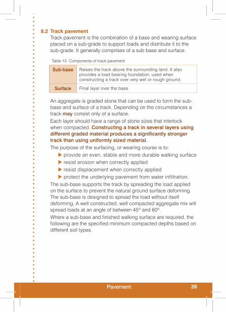
8.2 Track pavementTrack pavement is the combination of a base and wearing surface placed on a sub-grade to support loads and distribute it to the sub-grade. It generally comprises of a sub base and surface.
An aggregate is graded stone that can be used to form the sub-base and surface of a track. Depending on the circumstances a track may consist only of a surface. Each layer should have a range of stone sizes that interlock when compacted. Constructing a track in several layers using different graded material produces a significantly stronger track than using uniformly sized material.The purpose of the surfacing, or wearing course is to:
provide an even, stable and more durable walking surface resist erosion when correctly applied resist displacement when correctly applied protect the underlying pavement from water infiltration.
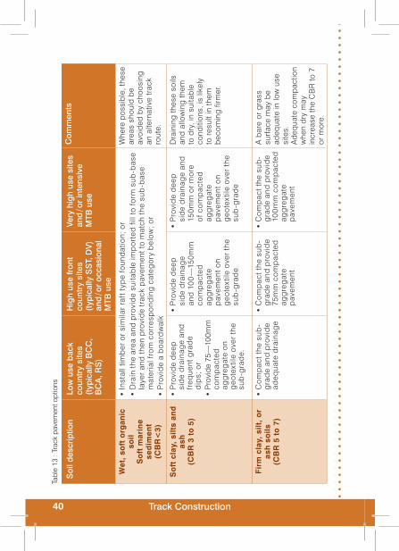
The sub-base supports the track by spreading the load applied on the surface to prevent the natural ground surface deforming. The sub-base is designed to spread the load without itself deforming. A well constructed, well compacted aggregate mix will spread loads at an angle of between 45º and 60º.Where a sub-base and finished walking surface are required, the following are the specified minimum compacted depths based on different soil types.
Table 12: Components of track pavement
Sub-base Raises the track above the surrounding land. It also provides a load bearing foundation, used when constructing a track over very wet or rough ground.
Surface Final layer over the base
40 Track Construction
Soi
l des
crip
tion
Low
use
bac
k co
untr
y si
tes
(typ
ical
ly B
CC
, B
CA
, RS
)
Hig
h us
e fr
ont
coun
try
site
s (t
ypic
ally
SS
T, D
V)
and
/ or
occa
sion
al
MTB
use
Very
hig
h us
e si
tes
and
/ or
inte
nsiv
e M
TB u
se
Com
men
ts
Wet
, so
ft o
rgan
ic
soil
So
ft m
arin
e se
dim
ent
(CB
R<
3)
Inst
all t
imb
er o
r si
mila
r ra
ft t
ype
foun
dat
ion;
or
• D
rain
the
are
a an
d p
rovi
de
suita
ble
imp
ort
ed f
ill to
form
sub
-bas
e •
laye
r an
d t
hen
pro
vid
e tr
ack
pav
emen
t to
mat
ch t
he s
ub-b
ase
mat
eria
l fro
m c
orr
esp
ond
ing
cat
ego
ry b
elo
w;
or
Pro
vid
e a
bo
ard
wal
k•
Whe
re p
ossi
ble
, the
se
area
s sh
ould
be
avoi
ded
by
choo
sing
an
alte
rnat
ive
trac
k ro
ute.
So
ft c
lay,
sil
ts a
nd
as
h(C
BR
3 t
o 5
)
Pro
vid
e d
eep
• si
de
dra
inag
e an
d fr
eque
nt g
rad
e d
ips;
or
Pro
vide
75—
100m
m
• co
mp
acte
d ag
gre
gat
e o
n g
eote
xtile
ove
r th
e su
b-g
rad
e.
Pro
vid
e d
eep
• si
de
dra
inag
e an
d 1
00
—15
0mm
co
mp
acte
d ag
gre
gat
e p
avem
ent o
n g
eote
xtile
ove
r th
e su
b-g
rad
e
Pro
vid
e d
eep
• si
de
dra
inag
e an
d 15
0mm
or
mo
re
of c
om
pac
ted
agg
reg
ate
pav
emen
t on
geo
text
ile o
ver
the
sub
-gra
de
Dra
inin
g th
ese
soils
an
d a
llow
ing
them
to
dry
, in
suita
ble
co
nditi
ons,
is li
kely
to
res
ult i
n th
em
bec
omin
g fi
rmer
.
Fir
m c
lay,
sil
t, o
r as
h s
oil
s(C
BR
5 t
o 7
)
Co
mp
act t
he s
ub-
• g
rad
e an
d p
rovi
de
adeq
uate
dra
inag
e
Co
mp
act t
he s
ub-
• g
rad
e an
d p
rovi
de
75m
m c
om
pac
ted
agg
reg
ate
pav
emen
t
Co
mp
act t
he s
ub-
• g
rad
e an
d p
rovi
de
100m
m c
om
pac
ted
agg
reg
ate
pav
emen
t
A b
are
or g
rass
su
rfac
e m
ay b
e ad
equa
te in
low
use
si
tes.
Ad
equa
te c
omp
actio
n w
hen
dry
may
in
crea
se th
e C
BR
to 7
or
mor
e.
Tabl
e 13
: Tr
ack
pave
men
t opt
ions

41Pavement
Soi
l des
crip
tion
Low
use
bac
k co
untr
y si
tes
(typ
ical
ly B
CC
, B
CA
, RS
)
Hig
h us
e fr
ont
coun
try
site
s (t
ypic
ally
SS
T, D
V)
and
/ or
occa
sion
al
MTB
use
Very
hig
h us
e si
tes
and
/ or
inte
nsiv
e M
TB u
se
Com
men
ts
Wel
l co
mp
acte
d
clay
, p
um
ice
or
bro
wn
ash
so
ils
(CB
R 7
or
mo
re)
No
ne;
or
• P
rovi
de
50m
m
• la
yer
of c
om
pac
ted
agg
reg
ate
Pro
vid
e 50
mm
•
laye
r of
co
mp
acte
d ag
gre
gat
e
Pro
vid
e 75
mm
•
laye
r of
co
mp
acte
d ag
gre
gat
e
A b
are
or g
rass
su
rfac
e m
ay b
e ad
equa
te in
low
use
si
tes.
Lo
ose
gra
vel:
Bea
ch o
r ri
ver
gra
vel
Sco
ria
San
d
No
ne•
C
om
pac
t the
sub
-•
gra
de
and
pro
vid
e 50
mm
co
mp
acte
d ag
gre
gat
e p
avem
ent
Co
mp
act t
he s
ub-
• g
rad
e an
d p
rovi
de
75m
m c
om
pac
ted
agg
reg
ate
pav
emen
t
Ad
diti
on o
f silt
and
cl
ay fi
nes,
mix
ing
and
com
pac
ting
may
p
rovi
de
a su
itab
le
surf
ace
in s
ome
site
s.
Co
mp
act
gra
vel;
W
eath
ered
ro
ckN
one
•
No
ne;
or
• P
rovi
de
50m
m
• co
mp
acte
d su
rfac
ing
agg
reg
ate
laye
r.
No
ne;
or
• P
rovi
de
50m
m
• co
mp
acte
d su
rfac
ing
agg
reg
ate
laye
r.
Ag
gre
gat
e su
rfac
ing
pro
vid
ed to
leve
l out
un
-eve
nnes
s in
the
sub
-gra
de.
Tab
le 1
3: G
ener
al n
ote
s
1 C
BR
= C
alifo
rnia
n B
earin
g R
atio
(ca
n b
e m
easu
red
usi
ng S
cala
pen
etro
met
er, C
leg
g H
amm
er o
r ot
her
app
roxi
mat
e m
eans
).
2. P
avem
ent a
ggre
gate
max
imum
sto
ne s
ize
shou
ld b
e no
t mor
e th
at 4
0% o
f the
inte
nded
com
pact
ed la
yer
thic
knes
s i.e
., 20
mm
max
imum
sto
ne fo
r 50
mm
thic
k pa
vem
ent l
ayer
, 40m
m m
axim
um s
tone
for
100m
m th
ick
pave
men
t lay
er.
3. W
here
the
reco
mm
end
ed to
tal p
avem
ent l
ayer
is 1
50m
m o
r m
ore,
ther
e m
ay b
e b
enef
it in
ap
ply
ing
this
as
two
laye
rs –
i.e.
one
100
mm
thic
k la
yer
of G
AP
40 a
gg
reg
ate
and
a s
urfa
ce la
yer
of G
AP
20 a
t 50m
m th
ickn
ess)
.
42 Track Construction
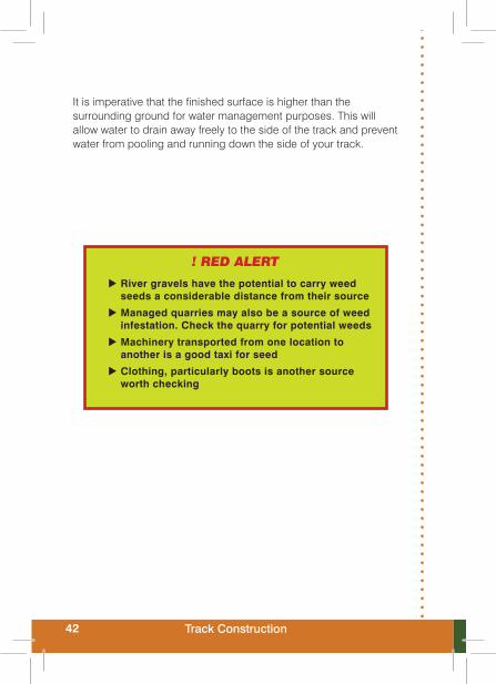
It is imperative that the finished surface is higher than the surrounding ground for water management purposes. This will allow water to drain away freely to the side of the track and prevent water from pooling and running down the side of your track.
! RED ALERT
River gravels have the potential to carry weed seeds a considerable distance from their source
Managed quarries may also be a source of weed infestation. Check the quarry for potential weeds
Machinery transported from one location to another is a good taxi for seed
Clothing, particularly boots is another source worth checking
43Compaction
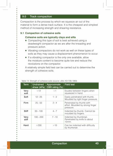
9.0 Track compaction
Compaction is the process by which we squeeze air out of the material to form a dense track surface. It is the cheapest and simplest method of increasing strength and shearing resistance.
9.1 Compaction of cohesive soils
Cohesive soils are typically clays and siltsCompacting this type of soil is best achieved using a ♦deadweight compactor as we are after the kneading and pressure action.Vibrating compactors do not work as well on these types of ♦soils as they may cause a displacement phenomenon to occur.If a vibrating compactor is the only one available, allow ♦the moisture content to become quite low and reduce the revolutions on the compactor.
A relatively simple field test can be carried out to determine the strength of cohesive soils.
Table 14: Strength of cohesive soils (source: after AS1726-1993)
Term Undrained shear (kPa)
Approximate CBR rating (%)
Field test
Very soft
<12 <1 Exudes between fingers when squeezed in hand.
Soft 12 – 25 1 – 2 Easily penetrated with thumb. Moulded by light finger pressure.
Firm 25 – 50 2 – 4 Penetrated by thumb with effort. Moulded by strong finger pressure.
Stiff 50 – 100 4 – 7 Indented by thumb. Cannot be moulded by fingers.
Very stiff
100 – 200 7 – 10 Indented by thumbnail. Penetrated by knife to about 15mm.
Hard >200 >10 Can be indented with difficulty by thumbnail.

44 Track Construction
HOT TIPSOn cohesive soil allow the soil to dry out so the moisture content is low to achieve good compaction.
When unable to use a static compactor, use a vibrating plate compactor but reduce the revs down to the minimum.
9.2 Compaction of granular soilsNon-cohesive materials require a vibration action to 'lock' the particles in place.
This shaking is delivered using a vibrating compactor. The ♦vibrating compactor should only be used to lock the particles. Ideally, the granular material is finished off with a deadweight ♦roller. However, the size of most deadweight rollers and the nature of the terrain often makes them difficult to use.Compact until the field test, as outlined in ♦ Table 15 (p.47), gives a good result.
In most situations you have to work with the available material. However, in many front-country sites with relatively high visitor numbers, applying well graded metal to the track surface is appropriate.
Material needs to be angular not rounded, as this allows it to ♦lock together.Rounded stones move easily and displace very quickly. Visitors ♦walking on rounded material will quickly move it either off to the side of the track or into a side drain.Material should contain a proportion of clay fines as it helps to ♦bind the other particles.Well graded material has a range of particle sizes and this ♦is the product we should aim to use. When a load is applied (static or vibrating plate compactor) the particles are able to lock together and voids are filled by the smaller sized particles. This produces a track surface that is dense and significantly stronger than poorly graded material. Maximum stone size is 20 mm which is suitable for almost all ♦track work.

45Compaction
9.3 Optimum moisture content (OMC)
Optimum Moisture Content is the term used to describe the moisture content of material and is the key to effective compaction. A material that is ideal for compaction will reach a point of maximum strength at certain moisture content.
HOT TIPStockpiled aggregate is likely to be at roadends or close to rivers.
Ensure material is at OMC prior to transporting. It is easier to apply water at these locations than when the material is spread on
the track surface.
If material is compacted when too dry its overall density will ♦be less and therefore its strength will be less. More effort is required to compact too dry material and the final density is likely to be less than if compacted at OMC.If material is compacted with moisture content higher than ♦OMC then compaction will have little effect.
9.3.1 Field Test for Optimum Moisture ContentA simple and reliable method of testing for OMC in the field is ‘the squeeze test’ and this works for most materials we deal with.
Remove as many of the particles over 5 mmin diameter as ♦possible; we just want the fines as the squeeze test will not work with large particles.Squeeze a handful of material as hard as you possibly can in ♦the palm of your hand.
When you open your hand the material falls into one of three categories:
falls apart and looks dry – is too dry and needs water added falls apart and looks shiny – is too wet and needs to dry out stays together in shape and has a dullish appearance — OMC!
! PITFALLMake sure you test four to five random locations from the pile of material. Testing from one spot may give an incorrect result
for the overall OMC of the pile.

46 Track Construction
9.4 Compaction techniqueBecause compaction is the cheapest and simplest method for increasing strength, it is very important to follow a procedure to achieve satisfactory compaction uniformly across the entire track surface, while maintaining shape and evenness of the surface.
Pavement material should not be compacted in layers ♦exceeding 150 mm.Compaction should begin on the outer (lower) edge of the ♦pavement and progress towards the centreline. Compacting from inside to outside will cause material to be pushed downslope and cause loss of shape.A forward and reverse pass is made over the same section of ♦pavement before moving to the adjacent section. It is important this is done. When changing direction the compactor should be on the previously compacted section.Each pass of the compactor should overlap the previous one ♦by a third to ensure complete coverage.Vibrating compactors. Turn the vibrator off when the machine is ♦stopping or turning.Reverse compactors without any jolting. Sharp turns or sudden ♦changes in direction should be avoided.The best speed is usually a slow walking pace. ♦When using a vibrating compactor, a sequence consisting of a ♦non vibrating pass, followed by several high amplitude passes, and finishing with low amplitude passes, has been found to achieve good compaction and surface thickness.Depending on the weather a light sprinkling of water will be ♦necessary to maintain OMC.
! PITFALLRunning the compactor down the centre of a
crowned track flattens the top !
47Compaction
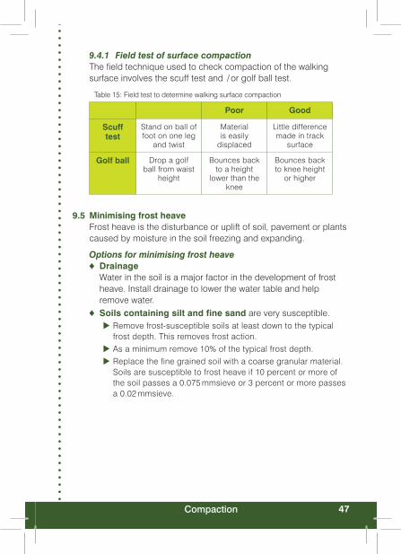
9.4.1 Field test of surface compactionThe field technique used to check compaction of the walking surface involves the scuff test and / or golf ball test.
Table 15: Field test to determine walking surface compaction
Poor Good
Scuff test
Stand on ball of foot on one leg
and twist
Material is easily
displaced
Little difference made in track
surface
Golf ball Drop a golf ball from waist
height
Bounces back to a height
lower than the knee
Bounces back to knee height
or higher
9.5 Minimising frost heaveFrost heave is the disturbance or uplift of soil, pavement or plants caused by moisture in the soil freezing and expanding.
Options for minimising frost heaveDrainage ♦Water in the soil is a major factor in the development of frost heave. Install drainage to lower the water table and help remove water.Soils containing silt and fine sand ♦ are very susceptible.
Remove frost-susceptible soils at least down to the typical frost depth. This removes frost action. As a minimum remove 10% of the typical frost depth. Replace the fine grained soil with a coarse granular material. Soils are susceptible to frost heave if 10 percent or more of the soil passes a 0.075 mmsieve or 3 percent or more passes a 0.02 mmsieve.

48 Track Construction
10.0 Geotextiles
The purpose of using geotextiles under the track formation is to prevent the mixing of materials. Generally, there are only two geotextiles used in construction of tracks; filter fabrics and geocells.
10.1 Filter fabricsUse when there is a need to separate material and stop fines ♦(clay or silt) from contaminating the track pavement.Is semi-permeable and allows water to seep through and drain. ♦
10.1.1 Construction using filter fabric Excavate the track foundation as you would to ♦construct an aggregate track.Form an even and level base; remove any material that may ♦puncture or distort the matting.If the surface is very wet, form sides by using good size soil ♦turves. These are laid over top of the filter fabric edge.To prevent mixing the material, where applicable, the filter ♦fabric may extend halfway up the formed sides.Line the formation with filter fabric and cut it to the required width. ♦To navigate bends, fold or cut the filter fabric. If you cut it ♦overlap by a minimum of 300 mm.Where there is a culvert pipe, proceed as if installing a culvert. ♦When the trench is formed lay filter fabric across its entire length.Take care not to puncture the filter fabric when compacting ♦around the culvert.Secure all edges using ground staples placed at intervals not ♦exceeding one metre.Filter fabric should be well covered with none exposed. ♦
Figure 8: Correct application of geotextile cloth
49Geotextiles
10.2 GeocellsGeocells are very effective at holding material in place.
Use them in very high use sites which have extreme weather ♦conditions and erodible soils.The objective of geocells is to stop soil erosion when the track ♦surface has lost shape or disappeared.
10.2.1 Construction using geocellsLook at the existing alignment and determine if you want stay ♦with it or re-route.If the existing alignment is badly eroded, the track can ♦become the side drain with a new track formed alongside.If necessary, excavate to the required gradient and width ♦removing all vegetation material.Taking the grade out may mean installing short sections of steps. ♦
Install side drains and culverts. ♦Ensure the sub-grade has a smooth finish with no protrusions ♦(rocks, tree roots).A side edge is unnecessary, but if installing one be careful to ♦get timber at the correct level. Allow for thickness of the track surface and geocells.Form sub-grade to required shape, crossfall and compact. ♦Add material to obtain the required level — correct crossfall of ♦2° (3% – 4%).Cut the geocells and place. ♦Complete one single pass of the compactor. ♦Secure geocells using 12 mm reinforcing rod and mortar. ♦Add suitable fill to geocells. ♦Complete one single pass with the compactor. ♦Apply track surface material ♦Shape to the correct crossfall of 2° (3% – 4%) and compact. ♦
HOT TIPSIf stockpiling unbagged material, lay it on top of a tarpaulin
to minimise impacts and maximise its use.
When transporting, storing or spreading metal aggregate be very careful NOT TO SEPARATE the fines. At all times keep the mix well graded.

50 Track Construction
11.0 Step construction techniques
During your office based planning you may have discovered that additional techniques are required to achieve the height gain required within the available topography. There are a number of solutions available; steps, switchbacks, climbing turns, inslope turns and steps.
11.1 StepsPlan well before any work is begun.
Avoid constructing long straight flights of steps. ♦Consider the landscape — stringer steps should be broken up ♦with landings and bends.By installing the right number of steps at the appropriate time ♦it’s possible to decrease the track gradient between flights.Install steps on the maximum rise to achieve a good track ♦gradient and also balance ‘how the steps visually fit within the landscape’.View where steps will be located from above to get a good ♦idea where visitors may take short cuts.
Figure 9: Change the angle of steps to alleviate long visual lines
There are three types of step formation: stringer steps, in-ground boxed steps and natural rock steps. There is likely to be some variation on each of these throughout the country and a number of designs are available.

51Step construction techniques
11.2 Stringer step surveySurvey the slope, then design the flights and landings. ♦Place the Marker at the top of the slope with a pole marked at ♦the Observer’s eye level. Place the pole at the top of the slope. ♦Attach a tape to the bottom of the pole; the Observer walks to ♦the bottom of the slope unreeling the tape.Observer notes the slope angle with the inclinometer or Abney ♦and records the slope length.Complex slopes are measured by repeating the process at ♦each change in the slope angle.
11.3 Stringer step constructionUse the correct geometric design. ♦Construct steps the same width as the track. ♦Steps are either pre-cut in the workshop and assembled on ♦site or prefabricated and transported to site assembled.Prepare the location by removing humps and other obstacles ♦to establish the required gradient.Sit the steps in place and install at the correct gradient. ♦Stand back to line them up with the track. ♦Check the steps are level. ♦Secure them with 50 x 50 mm x 750 mm pegs at a minimum of ♦600 mm centres.Place geocells under the first riser to prevent soil erosion. ♦Backfill steps with suitable local material that won't heave with ♦frost or turn boggy when wet or, if not available, use a granular fill.Compact in layers not exceeding 150 mm. If there is not a ♦suitable compactor, compact manually with a rammer.If the local material is not suitable and granular fill is not ♦available, cover local material with filter fabric and apply well graded aggregate mix.If enough material is available, backfill the entire external length ♦of the stringer. Allow for drainage and compact if possible.In erosion prone soil install filter fabric and secure it in place. ♦Position locally sourced rocks (minimum size 50 mm) down the entire external length of the stringer.

52 Track Construction
Surface should be suitable local material or aggregate. ♦Shape finished surface to 1% outward crossfall. ♦Compact. ♦Make the track flat at the top and bottom of the steps. This ♦helps with water management and the displacement of material.Construct either a drainage dip or grade reversal no less than ♦one metre from the top of a flight of steps.Re-visit steps two months after installation to check for any ♦water management problems and refill treads if necessary.
11.4 Boxed stepsBoxed steps are constructed square boxes made from timber stacked one on top of the other.
11.5 Boxed step constructionBoxed step construction is appropriate where you need to construct the step across slope and / or a visually softer appearance is preferred. Large risers to the maximum allowable in the standard look better when constructed as a box step. The gentle segmented curve fits the place better than stringer steps when a number of steps or flights are required.
Use the correct geometric design. ♦Construct steps the same width as the track with a minimum ♦depth of 750 mm.Steps are either pre-cut in the workshop and assembled on site ♦or prefabricated and transported to site assembled.Start work from the bottom and progress up the slope. ♦Prepare the location by removing humps or other obstacles to ♦establish the required gradient.Lay out a hose or stringline on the desired curve to act as a ♦guide during construction.Each box section should sit square and level. Apart from the ♦first and last steps each box sits partly on the previous step.Place geocells under the first riser to prevent soil erosion. ♦In soft ground a 200 mm x 100 mm bearer plate may be ♦installed. It should be wider than the finished step width and fixed to the first box step. Excavate and install the first box section. ♦
53Step construction techniques
Fix two internal 50 x 50 mm x 750 mm pegs to the internal ♦corner of each box section. Pegs need to be installed 30 mm below the height of the tread riser. Sit the steps in place and adjust the angle to achieve the ♦desired segmented curve.From the top of the installed step excavate the bank ready ♦for the next step. Material can be placed in the previously constructed step for fill. Place the next box section on top of the previous step and check it is square and level. Repeat the process until complete. Stand back and view the steps from a distance to check the ♦alignment.Backfill with suitable local material or a granular fill. ♦If enough fill material is available backfill the entire external ♦length of the step construction works allowing for drainage. In erosion prone soil install filter fabric and secure the fabric in place. Position locally sourced rocks down the entire external length of the construction.Compact in layers not exceeding 150 mm. If there is not a ♦suitable compactor, compact manually with a rammer.Step surface should be suitable local material which will not ♦heave with frost or turn boggy when wet etc, or aggregate.Shape finished surface to 1% outward crossfall. ♦Construct either a drainage dip or grade reversal no less than ♦one metre from the top of a flight of steps.Make the track flat at the top and bottom of the step. This ♦helps with water management and the displacement of material.Re-visit steps two months after installation to check for any ♦water management problems and refill treads if necessary.
11.6 Rock stepsAim to keep things as natural as possible, even when this is not necessarily the easiest or cheapest option. Using natural rock steps has considerably less visual impact and when well constructed they will last almost indefinitely with virtually no maintenance.
54 Track Construction
There are a number of guidelines that should be followed when using stone:
stones need to be compatible with the environment the track passes throughstones should be taken over a large area and not ‘mined’ from one site.stones that are providing shelter for alpine vegetation should not be removed.
11.7 Rock step constructionWork from the bottom of the slope upwards. ♦Build in a cross fall or crown to shed water. ♦Place the weathered stone face to the surface. ♦Dig in a very stable anchor stone at the base of the flight of ♦steps. Needs to be large as it supports the weight of additional stones / steps.Ensure there is stone to stone contact. Overlap stones and ♦stagger joins.On steep grades embed the stone vertically with the longest ♦end in the ground.Use large stones on the outer edge, they are less likely to move ♦Use wedge stones to lock steps into place. ♦Side drains may be required on some slopes. ♦Construct a drainage dip or grade reversal no less than one ♦metre from the top of a flight of steps.Make the track flat at the top and bottom of the step to help ♦with water management and material displacement.

55Step construction techniques
HOT TIPS
Be consistent, keep the tread rise and tread going the same in each flight of steps
Where possible build above the ground. Occasionally some minor excavation may be required depending on the slope gradient
Minimum slope when installing steps is 18º
Allow for water drainage down the side of the steps
Avoid long runs of stringer steps; they don’t fit aesthetically
Each individual step needs to be compacted. Compact loose fill in layers not exceeding 150 mm
Stringer steps greater than three metres in length become difficult to handle
Construct landings with a maximum slope (<2º or 3.0%) to stop water from sitting
The junction at the bottom of the steps and the track should be flat. This helps to minimise user displace-ment of the track surface at the bottom of the step
Use H5 treated timber
Use suitable fill material
Construct a drainage dip or grade reversal at the top of each flight of steps; this prevents surface water from running down the steps. (Section 7.2.2 and 7.2.3)
Fill should be free from organic matter
Fill each step to the top of the tread riser and create a very slight outward slope
Insert geocells underneath the first riser to prevent erosion at the base of the flight of steps
If building stone steps construct the diagonals on an angle, this helps to counteract the structural, staircase effect. Stick to the correct tread rise and tread going design
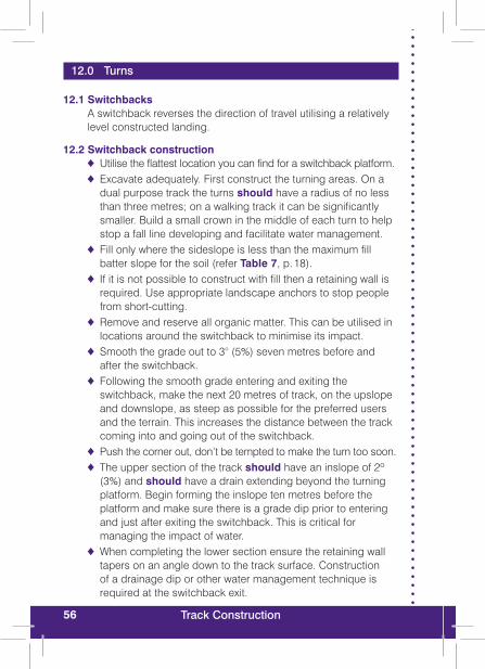
56 Track Construction
12.0 Turns
12.1 SwitchbacksA switchback reverses the direction of travel utilising a relatively level constructed landing.
12.2 Switchback constructionUtilise the flattest location you can find for a switchback platform. ♦Excavate adequately. First construct the turning areas. On a ♦dual purpose track the turns should have a radius of no less than three metres; on a walking track it can be significantly smaller. Build a small crown in the middle of each turn to help stop a fall line developing and facilitate water management.Fill only where the sideslope is less than the maximum fill ♦batter slope for the soil (refer Table 7, p. 18).If it is not possible to construct with fill then a retaining wall is ♦required. Use appropriate landscape anchors to stop people from short-cutting.Remove and reserve all organic matter. This can be utilised in ♦locations around the switchback to minimise its impact.Smooth the grade out to 3° (5%) seven metres before and ♦after the switchback.Following the smooth grade entering and exiting the ♦switchback, make the next 20 metres of track, on the upslope and downslope, as steep as possible for the preferred users and the terrain. This increases the distance between the track coming into and going out of the switchback.Push the corner out, don’t be tempted to make the turn too soon. ♦The upper section of the track ♦ should have an inslope of 2º (3%) and should have a drain extending beyond the turning platform. Begin forming the inslope ten metres before the platform and make sure there is a grade dip prior to entering and just after exiting the switchback. This is critical for managing the impact of water.When completing the lower section ensure the retaining wall ♦tapers on an angle down to the track surface. Construction of a drainage dip or other water management technique is required at the switchback exit.

57Turns
Avoid stacking switchbacks one above the other as it can ♦cause water management issues — water runs down the sideslope from one swichback to the next. Create long legs between turns, to help alleviate the ♦temptation to take shortcuts.Compact all fill material. ♦
Figure 10: Poor switchback locations lead to both user and water management issues
Figure 11: Variable length between switchbacks allows better water management, creates greater user interest and discourages shortcuts.
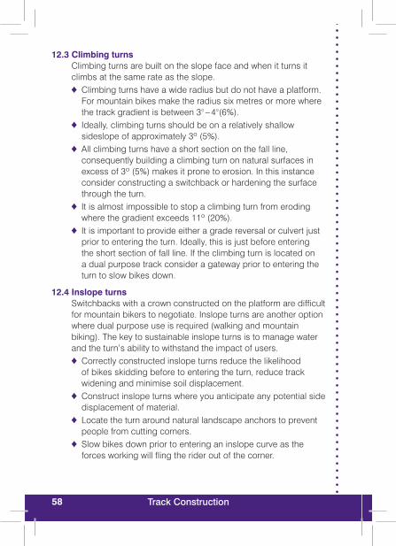
58 Track Construction
12.3 Climbing turns Climbing turns are built on the slope face and when it turns it climbs at the same rate as the slope.
Climbing turns have a wide radius but do not have a platform. ♦For mountain bikes make the radius six metres or more where the track gradient is between 3° – 4°(6%).Ideally, climbing turns should be on a relatively shallow ♦sideslope of approximately 3º (5%). All climbing turns have a short section on the fall line, ♦consequently building a climbing turn on natural surfaces in excess of 3º (5%) makes it prone to erosion. In this instance consider constructing a switchback or hardening the surface through the turn.It is almost impossible to stop a climbing turn from eroding ♦where the gradient exceeds 11º (20%).It is important to provide either a grade reversal or culvert just ♦prior to entering the turn. Ideally, this is just before entering the short section of fall line. If the climbing turn is located on a dual purpose track consider a gateway prior to entering the turn to slow bikes down.
12.4 Inslope turnsSwitchbacks with a crown constructed on the platform are difficult for mountain bikers to negotiate. Inslope turns are another option where dual purpose use is required (walking and mountain biking). The key to sustainable inslope turns is to manage water and the turn’s ability to withstand the impact of users.
Correctly constructed inslope turns reduce the likelihood ♦of bikes skidding before to entering the turn, reduce track widening and minimise soil displacement.Construct inslope turns where you anticipate any potential side ♦displacement of material.Locate the turn around natural landscape anchors to prevent ♦people from cutting corners.Slow bikes down prior to entering an inslope curve as the ♦forces working will fling the rider out of the corner.

59Turns
Build inslope turns on a gentle sideslope that does not exceed ♦14º (25%).When approaching and exiting the turn the track should run at ♦right angles to the sideslope.Build the inslope section on the turn through the fall line. ♦Correct placement of the inslope turn is critical to prevent water being trapped.Create a gateway on the uphill section prior to the turn. ♦Create a grade dip on the uphill section prior to the turn. ♦Turns should have a radius of between 3 and 5 metres. A ♦tighter turn for bikes needs to be negotiated at slower speed so tight turns do not require a built up bank. A radius any bigger than this results in increasing the length of the fall line (more potential problems), and bikes traveling at higher speeds creates a greater lateral displacement of track surface material. The steeper the sideslope, the higher and steeper the bank. ♦Only a very gentle inslope is needed make the turn work effectively. A slope as low as 3º (5%) from the outside to the inside of the turn generally works well.Cohesive soils should be used. Consider importing some clay ♦to add to your material.

60 Track Construction
13.0 Retaining walls
A retaining wall is a wall that is constructed to hold soil in place. A retaining wall over 1.2 metres should be designed by an engineer and 1.5 metres or more in height will require a building consent. The purpose of a retaining wall is to withstand horizontal pressure from the soil / material it is holding. These pressures can range from zero at the top of the wall to a maximum at the bottom of the wall; there is also some vertical pressure acting near the top of the wall.Although time consuming, where materials are available locally a stone retaining wall should be constructed. This 'fits' the landscape and allows for the creation of visually nice curves. Rock walls are rustic in appearance and given the isolated location of many walls drywall construction is ideal.
! PITFALLMake sure you check the effective fall height from the track. If the fall height exceeds 1.5
metres a barrier may be required.
Base Joints Outer face Headers
¹ / ³ to ½ wall height
Staggered a minimum of 150mm horizontally from the adjacent joint in the last row.
Inward slope of at least 3:1
Minimum 25% of the wall and have a length of 2.5 times their thickness ( at corners alternate headers should cross)
13.1 Specifications for rock retaining wall

61Retaining walls
13.1.1 Stone retaining wall constructionEstablish a solid foundation on firm soil or rock. ♦Inslope the foundation to match the desired batter of the wall. ♦Excavate the shelf slightly wider than the average width of the ♦rocks being used.Work from the low end of the foundation and build towards ♦the high. Use the largest rocks you have available.Dig foundation stones fully into the ground where possible. ♦Foundation stones are usually the largest stones used. At ♦least 50% of the stones should weigh 60 kg. Ideally, the remainder of stones should weigh 20kg.Ideal stone is rectangular with flat surfaces on four sides. The ♦worst rocks to use are rounded river rocks.The facestone of each tier overlaps the gaps between the ♦stones on the next tier down.Each tier includes header stones. ♦Each successive tier should be set back slightly to achieve ♦the desired batter.Stones in each tier should have three points of contact with ♦the stones below. There should be no wobble.Place wedges only on the inside of the wall, not the outside ♦face. This makes them less visible and when backfilled they won’t fall out. Don’t place them on the front face of the wall.Backfill and compact as you build. ♦Place a final layer of capstones, of a suitable size, so they ♦will not be easily dislodged on the top.
HOT TIPS
Save some large rocks for the top capping stones.
Rock is more likely to break where required to when placed on dirt to break as opposed to on another rock.

62 Track Construction
13.2 Specifications for timber retaining wall. Table 16: Specifications for timber retaining wall with concrete encased timber
posts at 1.2 m centres
Retaining on level ground with no traffic loading
Height max
Depth min
Post length
Small end diameter H5 Post
H5 Posts
Hole Rails
metres metres metres diametermm
diameter mm
metres
1.2 1.1 2.4 150 155 350 150 x
50mm RS
H51.4 1.3 2.7 175 180 350
Table 17: Specifications for timber retaining wall with concrete encased timber posts at 1.2m centres on sloping ground:
Retaining on sloping ground at 20º maximum
Height max
Depth min
Post length
Small end diameter H5 Post
H5 Posts
Hole Rails
metres metres metres Diametermm
Diameter mm
metres
1.0 1.0 2.1 150 155 350 150 x
50mm
RS H51.2 1.2 2.4 175 180 350
1.4 1.4 2.7 200 200 400
13.2.1 Timber retaining wall constructionDetermine the soil type. A firm clay soil is required. For ♦sand, gravel, soft or organic soils or compacted fill refer to a consulting engineer for specific design.
Determine the dimensions of the wall, so that quantities of ♦materials can be calculated.
Excavate and cut earth face no steeper than 60° to horizontal. ♦To prevent slips fresh excavations should not be left exposed ♦to wet weather.
Cut bank back a minimum of 400 mm to allow working space ♦access for nailing.
Ensure ground behind wall line slopes towards drainage. ♦Follow natural fall.

63Retaining walls
HOT TIPBrace posts using hex-head TEK screws, it is easier than
hammering in nails. If using nails, leave the heads proud and partly bent over for easy removal.
Dig the specified diameter holes at the specified centres, ♦without disturbing surrounding soil.An Auger or powered posthole borer is recommended. ♦Before setting posts, remove or compact loose soil in holes. ♦Set posts by adding or removing base metal. Set the end posts ♦in holes with specified lean-back. A post slope of 1 in 10 will improve the appearance and strength of the wall.Place concrete around the end posts of the wall first. ♦Concrete in post holes should be one part cement to six parts building mix or use pre-bagged concrete mix. Erect a string line.Check you have exactly the same lean on both posts. Use ♦level and hold plumb, measure back to post 100 mm. Set two string lines between the two end posts, first at ♦100 mm from top of post, second 100 mm from ground level. Pack string lines off the posts to give an offset line. Use string line to line up the intermediate posts. ♦Place concrete around all intermediate posts, ensuring ♦exact maximum spacings. Place concrete around posts and compact well by tamping. Use temporary bracing to protect poles against disturbance for at least two days. Use ground treated H5 rails as specified in Tables 16 and 17. ♦Fix to back of posts with 150 mmgalvanised nails. ♦Fix horizontal retaining wall timber to posts with galvanised ♦nails. Joints in the timber will need to be made at the centre of posts. Stagger the joints at different posts.Apply preservative to the end of every length of retaining wall ♦timber cut on site. Cut ends of posts will require preservative as well.

64 Track Construction
Use 50 mm bed of drainage metal, slope it in the direction of ♦the water flow outlet and leave the ends protruding a little to enable cleaning.Install 100 mm perforated drain pipe at the base of the ♦retaining wall below adjacent ground level with a filter-sock placed over it. Surround with AP20 scoria or other free draining material.Lay drain / coil, behind the wall, so it slightly falls in direction ♦of water flow outlet. Cover the coil with 250 mm of drainage metal.
Now you can eitherPosition sheets of hardboard, cardboard or plasterboard 250 mm behind the wall. Make sure they are all at the same level.Fill drainage metal between the sheets and wall to within 300 mm of ground level at the top of wall, and fill behind the sheets with soil or clay.
Or you canCut POLYFLOW® polystyrene sheets to shape with a handsaw or other cutting device. Position them directly against the retaining wall with the edge sitting on the drain. Cover the entire wall with up to 150 mmfrom the top of the wall.EPS contact adhesive may be used to temporarily hold POLYFLOW® in place before backfillingBackfill initially with a 200 mm layer of scoria or gravel, followed by free draining material. If excavated material from the site is used, it must have free-draining characteristics.Top with free draining gravel and cover with weedmat. Place topsoil on surface.
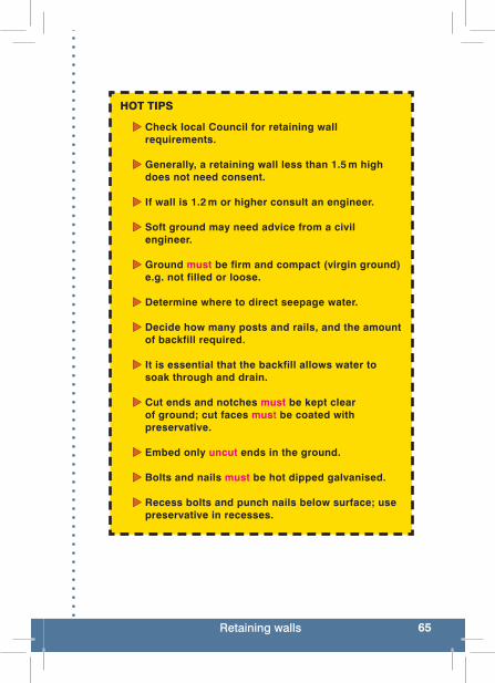
65Retaining walls
HOT TIPS
Check local Council for retaining wall requirements.
Generally, a retaining wall less than 1.5 m high does not need consent.
If wall is 1.2 m or higher consult an engineer.
Soft ground may need advice from a civil engineer.
Ground must be firm and compact (virgin ground) e.g. not filled or loose.
Determine where to direct seepage water.
Decide how many posts and rails, and the amount of backfill required.
It is essential that the backfill allows water to soak through and drain.
Cut ends and notches must be kept clear of ground; cut faces must be coated with preservative.
Embed only uncut ends in the ground.
Bolts and nails must be hot dipped galvanised.
Recess bolts and punch nails below surface; use preservative in recesses.

66 Maintenance
Section 3: Track Maintenance
14.0 Sustainable maintenance
Effective maintenance relies on sound technical knowledge and good management practices. The notion that a bit more effort today will save considerable time and money in the future has significant merit.
Key points for effective maintenance
Walking tracks DO NOT remain the same and 1. deterioration should be expected.
Causes of deterioration include — use, weather conditions, 2. construction standard and quality, materials used and lack of maintenance.
Good maintenance practices protect investment and meet 3. standards. Correct diagnosis is essential — the wrong diagnosis is costly in both labour and materials.
Restoring the correct crossfall during maintenance and 4. resurfacing is critical.
Maintain drainage systems to protect the pavement.5.
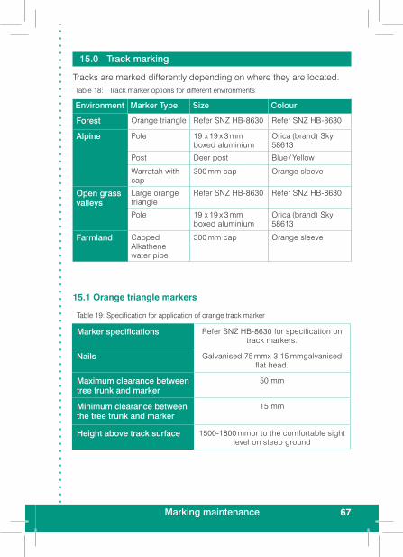
67Marking maintenance
Table 18: Track marker options for different environments
Environment Marker Type Size Colour
Forest Orange triangle Refer SNZ HB-8630 Refer SNZ HB-8630
Alpine Pole 19 x 19 x 3 mm boxed aluminium
Orica (brand) Sky 58613
Post Deer post Blue / Yellow
Warratah with cap
300 mm cap Orange sleeve
Open grass valleys
Large orange triangle
Refer SNZ HB-8630 Refer SNZ HB-8630
Pole 19 x 19 x 3 mm boxed aluminium
Orica (brand) Sky 58613
Farmland Capped Alkathene water pipe
300 mm cap Orange sleeve
15.0 Track marking
Tracks are marked differently depending on where they are located.
15.1 Orange triangle markers
Table 19: Specification for application of orange track marker
Marker specifications Refer SNZ HB-8630 for specification on track markers.
Nails Galvanised 75 mmx 3.15 mmgalvanised flat head.
Maximum clearance between tree trunk and marker
50 mm
Minimum clearance between the tree trunk and marker
15 mm
Height above track surface 1500-1800 mmor to the comfortable sight level on steep ground

68 Maintenance
Carefully remove all non-standard track markers and nails and ♦remove them from the site.Replace with orange plastic triangle markers as per specifica- ♦tions. Use at least two nails in each marker.Markers ♦ should be fixed with the apex pointing in the direction of travel. Markers ♦ must be fixed so that at any point the next marker is clearly visible within a comfortable sight line.
HOT TIP
Don’t drive nails flush with the tree, allow for tree growth. Markers will pop off in a few years if fixed flush with tree.
Track markers have a textured side and a smooth side. Check which surface provides the best visibility for visitors. In certain light, particularly when the sun hits the marker, the smooth side is very difficult to see.
HOT TIPS
Markers with less than 5 mm clearance between marker and tree trunk can have nails pulled out to 30 mm without damage to tree, marker or nail.
Pay particular attention to track junctions and points of entry into the bush from tops, rivers and slips etc.
Use large orange markers where points of entry are confusing or could prove to be in extreme weather.
Don’t attach markers to DOC signs, bridges or structures. It looks unprofessional and is unnecessary.

69Marking maintenance
15.1.1 Track marker orientationFix with the apex, pointed tip upright. Markers shall be used with the apex pointing in the correct direction, whenever there is a significant change in track direction that may cause people to walk off the track. As a general rule place markers as follows:
Track is straight, uphill or downhill —
.
Track has a slight change in direction to the left —
Track has a slight change in direction to the right —
Track takes a major turn to the left – place two markers like so. The addition of an extra marker will act as an alert for visitors.
Track takes a major turn to the right place two markers like so

70 Maintenance
15.2 Alpine polesTable 20: Specification for application of alpine poles
Marker specifications Refer to Table 18
Length 2.4 metres
Maximum clearance ground and top of marker
1.8 metres
Minimum clearance ground and top of marker
1.6 metres
In addition to the specifications outlined in SNZ HB-8630: 2004, locate markers where navigation is difficult, there is a change in direction or there are a number of leading ridges. Prominent tracks on ridgelines may not require markers and we don’t want the place visually polluted with markers.
HOT TIPTo make sure people get onto the correct ridge, where
there are a number of leading ridges and no clearly defined prominent track heading to the bushline, erect two large markers, one on the bushline and a second
100 metres up.
15.3 Open grass valleysTable 21 – Marker specifications for open grass valleys
Marker specifications Refer to Table 18
Length 1.8 metres
Maximum clearance ground and top of marker
1.2 metres
Minimum clearance ground and top of marker
0.9 metres

71Vegetation maintenance
15.4 FarmlandTable 22 – Marker specifications for farmland
Marker specifications Refer to Table 18
Length 1.8 metres
Maximum clearance ground and top of marker
1.2 metres
Minimum clearance ground and top of marker
0.9 metres
16.0 Vegetation maintenance
Vegetation maintenance can be broken down into a number of tasks, each requiring different skills. They include vegetation clearance, windfall removal, vista maintenance and the felling and removal of hazardous trees.
16.1 Minor vegetation clearanceCutting back the biomass is a never ending battle. However, we should not fall into the trap of over cutting vegetation as this can have an immediate impact for the visitor, they want to interact with the environment, not be removed from it. Over-cutting can have a profound effect on this interaction and should be avoided.
Guiding principlesConsider the experience the track offers and cut accordingly.1. Observe and understand the nature of the vegetation.2. Don’t prune if you don’t have to.3. If you have to prune make sure it is not obvious.4. Sometimes it may be better to remove the tree. 5.
HOT TIPThe intent of the track clearance standards is to reduce the width
of cut vegetation progressing from short walk to route. While the tramping track standard does not specify a maximum
width, common sense dictates it should be no greater than a Great Walk / Easy Tramping Track.

72 Maintenance
undercut the branch approximately 20–30cm from the trunk second cut should be 30–40 cm back from the trunk on the upper surface of the limbfinal cut is as close as possible to the trunk.
16.1.3 WindfallsLarge trees or limbs that fall across the track should be:
Cut back 300 mm from each side of the track edge and ♦parallel to the track.
Figure 12: Incorrect and correct tree branch pruning technique
16.1.1 Minor vegetation cuttingUse a nylon flail cord on the scrub cutter for clearing grass and ♦vegetation up to approximately 8 – 10 mm (thickness of a pencil).Remove cut vegetation from track surface and side drains: ♦
on easy accessible tracks, short walks and walking tracks, cuttings can be removed with a motorised blower.on tracks with difficult access use a rake.
Clear difficult to cut vegetation, such as flax, with a knife, or ♦sharp bladed tool, as close to the ground as possible.Hand pull seedlings for scenic vista maintenance ♦
16.1.2 PruningTrees and shrubs should be cut as close to the ground as possible using pruners, pruning saw or similar cutting tool.
Use the three cut method (B in Figure 12) to remove large ♦limbs from trees. This minimises the risk of damage to the tree and reduces the likelihood of disease.
A – Undesirable technique B – Best Practice

73Vegetation maintenance
16.1.4 Minor vegetation sprayingUse chemical sprays only when absolutely necessary. Some examples of when they are appropriate include:
When grass and plants start to emerge through the track surface. ♦Where plants such as stinging nettle, hook grass and toe toe ♦are prolific on short walks and walking tracks.Where controlling introduced plants such as gorse and broom ♦is required.
Spray vegetation only when manual control methods are impractical.
Where vegetation is emerging through the track surface spray ♦only the gravel surface in accordance with the track standard.
The exception is where a non grass killing herbicide is used to kill weeds on or adjacent to the track.
Cut tall vegetation first and remove to avoid large amounts ♦of dying and dead vegetation along the track. Leave enough foliage to absorb the spray.Spray the ♦ minimum area for good control.
HOT TIPS
Time vegetation cutting to allow for optimal flowering e.g. alpine plants should be cut at the end of the season.
Slower growing vegetation doesn’t need to be trimmed to the maximum width allowable in the track standards.
For large tree trunks make the cut at a sloping angle; this ♦helps to reduce the visual impact of clearing fallen trees.Large limbs should be removed so they are out of sight from ♦the track. Cut ends should face away from track so they are not visible to visitors.Employ a professional arborist when large trees require ♦pruning on scenic vista points.
!! RED ALERTResource Consent may be required when removing vegetation and
undertaking earthworks.
74 Maintenance
16.2 Vista maintenanceThere are many viewing platforms and scenic lookouts throughout the country. An important and often overlooked aspect is the long term management of the scenic view. There are a number of important aspects to consider:
All plant species must be in character with the site. ♦Plants must be able to grow in an often exposed location. ♦Rather than maintaining a clear view consider framing the view. ♦Plant species that even at their maximum height will not ♦obstruct the view.Annually remove a percentage of self germinating seedlings ♦that will eventually obstruct the view.For particularly difficult terrain and / or vegetation employ a ♦professional arborist.
17.0 Drainage system maintenance
Drainage system maintenance is the most important maintenance task to protect the investment made in the track.
17.1 Catch pits and side drainsCatch pits and side drains require regular maintenance. Keeping them free of sediment reduces the likelihood of blocked culverts. How and how often they are maintained will be dictated by a number of local factors including; forest type, rainfall and track gradient.
The ideal time is during wet weather. ♦Remove debris as it is likely to contain vegetative material and ♦should be disposed of.Check for scouring and protect where evident. ♦Where there is side drain scouring, line with filter fabric and ♦install local rocks (50 –100 mm). Make the side drains larger to accommodate the extra volume. Reform and re-establish to the specified width and depth. ♦Repair catch pit walls where there is material collapse. Protect ♦the walls by lining with rock.Re-establish the culvert invert. The bottom of the catch pit should ♦be a minimum of 100 mm below the bottom of the culvert.

75Drainage system maintenance
Remove any vegetation growing on the shoulder between ♦track surface and side drain.Start from the culvert catchpit and work up towards the next ♦culvert. This gives you the correct starting levelA motorised blower is an effective tool for removing leaf and ♦light twigs from side drains. Material is simply blown out of the drain and off to the downslope side of the track. The blower won’t remove fine soil particles. These must be removed to allow water to free flow, and prevent the creation of a dam which will facilitate the build up of additional material.
HOT TIPS
Maintain side drains when it is raining.
Discard material removed from the catchpit as it contains organic debris.
Get the drainage levels right with no small rises that will act as a dam. Use a long profile and check cleared depths for consistency.
Clear catch pits after significant rain of 100 mm or more.
In extreme situations, such as Fiordland, with large and deep side drains a small merchandised digger is best. However, the majority of side drains will be cleared manually with shovel and rakes.
! PITFALLMaking the side drains deeper each time they’re
maintained. Maintain to the correct depth.

76 Maintenance
17.2 CulvertsAdd additional culverts where evidence suggests ♦they are needed.Repair or replace culverts in poor repair. ♦Clean all debris from culvert entrances and exits. ♦Dispose of vegetation out of sight. ♦Extend or widen culvert discharge if there is an ♦inadequate discharge. Landscape the area to create a low area for the water to flow.Check culverts have 150 mm of cover over the pipe. ♦Add additional material when 100 mm minimum cover remains.Check from both directions that culverts are not ♦visible when walking the track. Check each culvert before proceeding to the next to ♦ensure that there are no inlet and outlet blockages.
17.3 Ford crossingsWell constructed ford crossings should require little maintenance if constructed soundly and properly.
Check for loose stones and re-pack. ♦Check all wedge stones and re-pack. ♦Check the stream level isn’t higher than the ♦constructed ford. If it is, extend the ford.Maintain the track leading onto the ford. ♦
18.0 Geotextiles maintenance
Cover exposed filter fabric; it is not UV stabilised and exposed matting looks awful.
77Track surface maintenance
19.0 Stone pitching maintenance
Stone pitching should require minimal maintenance. The main maintenance tasks are:
Check the stonework for any loose stones. ♦Re-set and repack any loose stones. ♦Check anchor stone is flush with track surface. If not, place additional ♦material until anchor stone and track surface are flush.
20.0 Track surface maintenance
The track surface, unless completely hardened, is going to wear and need maintenance. If well constructed the surface shouldn’t require as much maintenance as your drainage system. You will need to:
Replace displaced, eroded or compacted material to get the ♦track back to its original shape. Pull back material that has worked its way to the outer edge and ♦reshape the walking surface.Look for locations on the downslope side where water is having ♦trouble getting away and modify the drainage system.Scarify the existing metal surface before adding new material. ♦Use the teeth on a digger rock bucket, rotary hoe etc, to allow the product to lock together when compacted. If new material is just placed on top of the existing surface and compacted it won’t lock together very well and will disappear more rapidly.
HOT TIPS
Where a large proportion of fines have disappeared and the surface is looking “boney” apply a mix of sand and clay and compact the surface to form the desired seal
If the track is a crown shape it is important not to make a final pass down the centre of the track when finishing compacting, as this will remove the crown and accelerate deterioration.
Maintaining super-elevation on curves for mountain bikes is as important as maintaining the crown.
78 Maintenance
20.1 Surface scouring and trenchingScour is the loss of surface material caused by the flow of water along and / or over the track surface eventually forming a trench. This can be a serious problem on steep tracks and tracks of a constant gradient that have not been maintained. Scouring can be minimised by:
Increasing the strength of the pavement. ♦Decreasing the shear force caused by the flow of water. This ♦can be minimised through good design.
Surfaces with a high content of fines and small aggregates are more inclined to scour than those with well graded material.
PITFALLS ! Scouring is caused by:
Erosion prone soil. Steep track gradients. Lack of compaction; the surface has little strength and material is picked up and moved by visitors and water.Excessive long consistent gradients. Debris or berm on track shoulder preventing surface water from flowing off to the side.
HOT TIPThe most cost effective precaution against scouring is to pay
attention to drainage, material grading and track shape.
Surface scouring leads to further track deterioration through exposure to the environment. Scouring can become very pronounced when combined with material susceptible to movement.
Begin maintenance of a scoured track by slowing or diverting ♦water from the track. Look for locations where effective grade dips can be installed ♦— rolling dip, drainage dip, grade break.When the track is too steep and goes straight down the fall ♦line, install steps. Gradient must be over 18º.Sometimes re-routing a section of track is the best long term ♦solution.

79Slough and berm
21.0 Slough and berm
On tracks that traverse hillsides, slough is the term used for rock, soil and organic debris that accumulates in side drains or on the inside of the track if there is no side drain. Berm is material that has accumulated on the outside or downslope side of a track forming a dam that prevents water from shedding.
Removal of slough and berm is one of the most unglamorous ♦yet critical maintenance tasks and must be repeated again and again.Slough forces people to the outside of the track, potentially its ♦weakest part.The amount of slough depends on soil type, weather and the ♦batter slope. For tracks with side drains slough can be a real problem blocking the flow of water down the drain and forcing it across the track.
As discussed previously, over time tracks will change shape, material gets displaced and the track surface compacts further. This forms a berm on the outside edge of the track.
Berm formation is one of the biggest factors contributing to ♦scouring and trenching of the walking surface.Once a berm is formed water is unable to get off the track, ♦increases in volume and runs down gathering soil as it goes causing surface scouring and trenching.Loosen compacted slough and berm with a grubber or McLeod ♦tool.Remove slough and berm and reshape the track to its original ♦formation so water will run off.If you have surplus material, consider storing it for the future. It ♦will be needed at some future time to re-establish the track.
Not all slough is going to be suitable to use as track surface material. Some will contain organic material and should be scattered some distance from the edge of the track.
80 Maintenance
22.0 Steps maintenance
Well constructed steps (stringer, boxed and rock) should be almost maintenance free.
Check drainage down the side of the steps. ♦If there is scouring, increase width of the drainage channel, line ♦with filter fabric and fill with rocks (minimum 50 mm).Refill steps if material is sitting below the top of the tread riser. ♦
23.0 Switchbacks maintenance
Switchbacks require a high degree of maintenance, even more than a standard section of track. Maintaining the shape of a switchback is absolutely critical to its effectiveness and durability.
Remove slough and berm to restore original construction size. ♦Regrade the outslope of the lower track and the inslope on the ♦upper track.Remove all debris to ensure effective drainage. ♦Check retaining wall. ♦

81
Appendix: Slope inclinometer
How to check the accuracy A slope inclinometer is unlikely to fall out of adjustment unless it has sustained a knock of some sort. Dropping it on the ground is enough to knock it out of adjustment.
To check for accuracy select two objects approximately 10 ♦metres apart.Mark one of the objects at your eye level. ♦Walk to the second object and mark it at eye level. ♦Hold the inclinometer next to the mark and shoot the grade ♦back to the mark on the first object. Take note of the reading.Return to the first object and take a reading back to the second ♦object, shooting the inclinometer at the mark you made. Take note of the reading.
The two readings should be the same except one will be positive and the other negative (both may be zero if the ground was flat). A difference of 1º (1 – 2%) may be a matter of handling technique rather than the instrument. If the difference is greater and you do the exercise again with greater accuracy, and cannot erase the deviation then you should suspect that the inclinometer is out of adjustment. The bad news is there is no way of adjusting the inclinometer and it will need to be returned to the manufacturer for repair or replacement.
How to use a slope inclinometerSlope inclinometers have both percentage and degrees marked on them. Make sure you use the correct one or you will get quite a different result from what you may have anticipated.
Hold the inclinometer in your hand with the eyehole facing ♦toward you and the lanyard ring hanging down toward the ground.Ensure you do not block any of the natural light with your hand, ♦as the natural light illuminates the internal disc.Raise the inclinometer and look through it with your right eye, ♦keep your left eye open.As you look through the inclinometer with both eyes open you ♦will see that a line extends out across and into the landscape.
82
Choose something on the horizon and line up with the ♦horizontal mark in the inclinometer with the target.Move the inclinometer up and down and see the grade change. ♦The plus or minus sign tells you whether the grade is rising or ♦falling.
Read grade where the horizontal line crosses the scale. Slope inclinometers have both degrees and percentage marks. Make sure you read the scale you are working with or you will get quite a different result from what you anticipate.
For more information
Track Construction and Maintenance Guidelines — VC 1672 on the DOC Intranet