track motion foundry irbt 4003f/6003f/7003f 7109-1 rev. 8, february 2006 i contents product manual...
TRANSCRIPT

Product ManualTrack Motion Foundry
IRBT 4003F/6003F/7003F
3HXD 7109-1 Rev. 8, February 2006

The information in this document is subject to alteration without prior notice and should not be regarded as an undertaking from ABB Automation Technologies AB. ABB Automation Technologies AB assumes no responsibility for errors that may occur in this document.
ABB Automation Technologies AB bears no responsibility for damage that is a consequence of using this document or the software or hardware described in this document.
The document, or parts of it, may not be reproduced or copied without prior permission from ABB Automation Technologies AB. It may neither be imparted to a third party nor otherwise be used without authorization. Infringement hereof will be subject to action in accordance with applicable laws.
Further copies of this document can be obtained from ABB Automation Technologies AB at current prices.
© 2003 ABB Automation Technologies AB
ABB Automation Technologies ABRobotics & Manufacturing
SE-695 82 LaxåSweden
3HXD 7109-1 Rev. 8, February 2006 i
Contents
Product ManualTrack Motion FoundryIRBT 4003F/6003F/7003F
Specification Tab 1:
Description 1
Safety instructions 5
Technical specifications and requirements 9
Variants and options 15
Installation and operation Tab 2:
Unpacking and handling 1
Mechanical installation 5
Electrical installation 17
Commissioning 23
Maintenance Tab 3:
Maintenance intervals 1
Maintenance instructions 3
Spare parts 19

ii 3HXD 7109-1 Rev. 8, February 2006

3HXD 7109-1 Rev. 8, February 2006 Specification i
Sp
ecif
icat
ion
Tab 1: Specification1 Description 1
1.1 General 1
1.2 Principle layout 21.2.1 IRBT 4003F/6003F/7003F 2
1.3 Terms and concepts 31.3.1 Definitions 3
2 Safety instructions 5
2.1 Description 5
2.2 Safety with Unpacking and handling 52.2.1 Lifting instructions 5
2.3 Safety with mechanical installation 62.3.1 Safety distance 6
2.4 Safety with Assembling the cable channel and robot 62.4.1 Assemble the robot 6
2.5 Safety with Electrical installation 62.5.1 The robot’s cable harness 6
2.6 Safety with Commissioning 72.6.1 Calibration 72.6.2 Checking the working area 7
3 Technical specifications and requirements 9
3.1 Performance 93.1.1 IRBT 4003F IRB 4400 (Low voltage) 93.1.2 IRBT 6003F IRB 6400R (Low voltage) 93.1.3 IRBT 6003F IRB 6600 (High voltage) 103.1.4 IRBT 7003F IRB 7600 (High voltage) 10
3.2 Dimensions 113.2.1 Length measurement 113.2.2 Width and height measurements 12
3.3 Load on cover plate 133.3.1 Max load 13
3.4 Technical requirements for the robot 143.4.1 Hardware requirements 14
4 Variants and options 15
4.1 Variants and options to the IRBT 4003F/6003F/7003F 154.1.1 Connection cable 154.1.2 Power cable 154.1.3 Ordering list 154.1.4 Options 16

Specification ii 3HXD 7109-1 Rev. 8, February 2006
Sp
ecification

DescriptionGeneral
3HXD 7109-1 Rev. 8, February 2006 1-1
Sp
ecif
icat
ion
1 Description
1.1 General
Track Motion IRBT 4003F/6003F/7003F expands the movement pattern of the robot with an extra degree of programmable freedom.
High performance - High precision
IRBT 4003F/6003F/7003F has a powerful motor and an advanced gearbox. Together they give the track motion good acceleration and speed performance at the same time as precision is extremely high.
Function The track motion is supplied with carriage and adaptor plate for robot models: IRB 7600, 6600, 6400R or IRB 4400. No further adaptation is necessary, which means easy installation. The design of the track motion has also been adapted to give the shortest possible installation time.Movement on the track motion is programmed using the robot controller in the same way as the robot’s other axes.
Cable chain IRBT 4003F/6003F/7003F has a covered, steel cable chain.
Flexibility As the track motion is based on two and three metre modules makes it very flexible. There is also a possibility to add one or more modules at a later date.
Fully-fitted cover plates
The track motion’s cover plate is a full length “Tear plate”. This means IRBT 4003F/6003F/7003F is sealed and easy to keep clean. The plate is also safe to walk on.

Description
Principle layout
1-2 3HXD 7109-1 Rev. 8, February 2006
Sp
ecification
1.2 Principle layout
Track Motion IRBT 4003F/6003F/7003F is available in a basic version where the cable chain is protected by a steel band.
1.2.1 IRBT 4003F/6003F/7003F
The illustration shows the principle layout of the track motion.
IRBT 4003F/6003F/7003F
Component parts The table refers to the positions in the illustration above.
12
6
3
9
4
8
7
5
10
Description Item
Gear rack 1
Linear guides 2
Motor 3
Brake release box only for the IRB 6600 and IRB 7600 4
Carriage 5
End-plate 6
Cable chain 7
Gearbox 8
Cable tray 9
Connection point J 10
DescriptionTerms and concepts
3HXD 7109-1 Rev. 8, February 2006 1-3
Sp
ecif
icat
ion
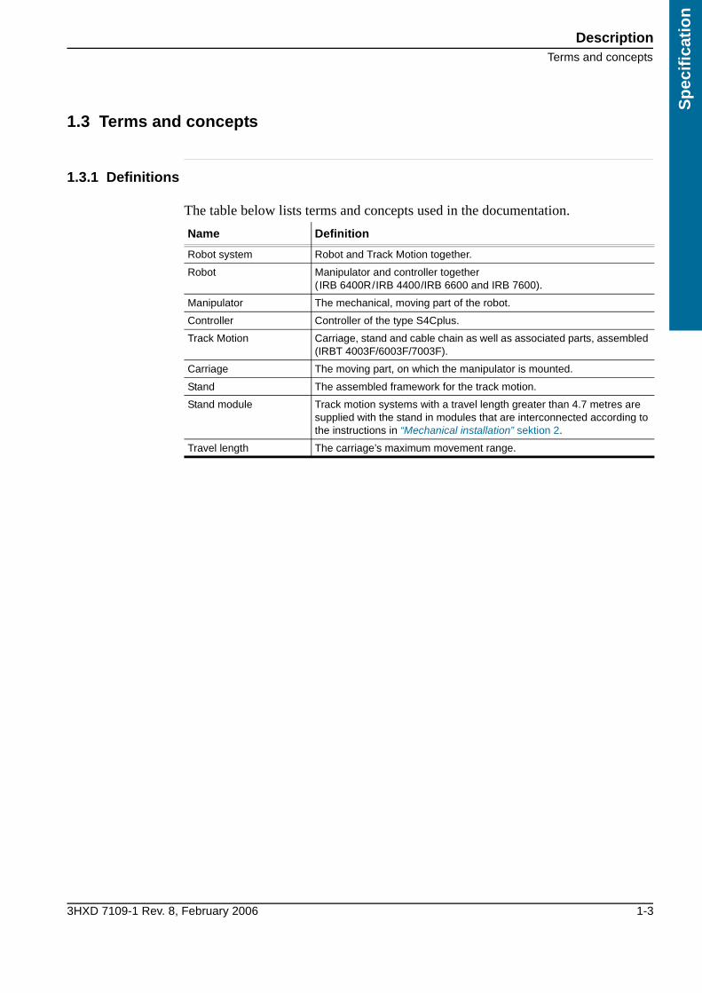
1.3 Terms and concepts
1.3.1 Definitions
The table below lists terms and concepts used in the documentation.
Name Definition
Robot system Robot and Track Motion together.
Robot Manipulator and controller together(IRB 6400R/IRB 4400/IRB 6600 and IRB 7600).
Manipulator The mechanical, moving part of the robot.
Controller Controller of the type S4Cplus.
Track Motion Carriage, stand and cable chain as well as associated parts, assembled (IRBT 4003F/6003F/7003F).
Carriage The moving part, on which the manipulator is mounted.
Stand The assembled framework for the track motion.
Stand module Track motion systems with a travel length greater than 4.7 metres are supplied with the stand in modules that are interconnected according to the instructions in “Mechanical installation” sektion 2.
Travel length The carriage’s maximum movement range.

Description
Terms and concepts
1-4 3HXD 7109-1 Rev. 8, February 2006
Sp
ecification

Safety instructionsDescription
3HXD 7109-1 Rev. 8, February 2006 1-5
Sp
ecif
icat
ion
2 Safety instructions
2.1 Description
There are safety instructions in this chapter for all steps that involve a risk of personal injury or material damage. In addition, they are written out by the instructions for each step.General warnings where the intention is to avoid difficulties are only set out by the instruction in question.
Key to symbols The different types of warnings are set out in the following chapters according to the table below:
2.2 Safety with Unpacking and handling
Read carefully through the safety instructions, before the track motion is unpacked and installed.
2.2.1 Lifting instructions
Only units that are 6 metres or shorter may be lifted. If the units are joined, the joints must be prefitted on delivery.
Symbol Importance
Warns for the risk of personal injury or serious damage to the product. Always follow the instructions expressed in association with this symbol.
Draws your attention to the fact that damage to the product can occur if a measure is not performed or is performed incorrectly.
Information about important details.

Safety instructions
Safety with mechanical installation
1-6 3HXD 7109-1 Rev. 8, February 2006
Sp
ecification
2.3 Safety with mechanical installation
2.3.1 Safety distance
The distance between the expander bolt and the gear wheel guard must be at least 10 mm. See the illustration.
Distance between levelling bolt and gear wheel guard.
2.4 Safety with Assembling the cable channel and robot
2.4.1 Assemble the robot
Always refer to the documentation for the manipulator when the manipulator is to be lifted.
2.5 Safety with Electrical installation
2.5.1 The robot’s cable harness
Make sure that the cable harness cannot come into contact with any moving parts.
Min. 10 mm

Safety instructionsSafety with Commissioning
3HXD 7109-1 Rev. 8, February 2006 1-7
Sp
ecif
icat
ion
2.6 Safety with Commissioning
2.6.1 Calibration
Make sure no persons are on the track motion when the carriage moves. Also make sure that the track motion’s cover plates are free from loose objects, otherwise these can become trapped between the carriage and the plates.
2.6.2 Checking the working area
The track motion’s working area must be inspected before the system is commissioned.
Safety instructions
Safety with Commissioning
1-8 3HXD 7109-1 Rev. 8, February 2006
Sp
ecification

Technical specifications and requirementsPerformance
3HXD 7109-1 Rev. 8, February 2006 1-9
Sp
ecif
icat
ion
3 Technical specifications and requirements
3.1 Performance
3.1.1 IRBT 4003F IRB 4400 (Low voltage)
The table below contains important technical data for the performance of the track motion.
3.1.2 IRBT 6003F IRB 6400R (Low voltage)
The table below contains important technical data for the performance of the track motion.
Function Performance
Travel length 1.7-7.7 metres in increments of 1 metre.
Travel speed IRBT 4003F 1.6 m/s
Stand length Travel length + 1.3 metres
Acceleration 1.4 m/s2
Retardation 1.9 m/s2
Repeater accuracy1
1. Repeated stopping in the travel direction, at the same point.
± 0.1 mm
Maximum load IRB 4400 the robot weight +100 kg
Weight carriage 600 kg
stand 270 kg/m
Adaptor for IRB 4400 160 kg
Degree of protection IP 67
Static play Contact ABB for information
Dynamic play Contact ABB for information
Function Performance
Travel length 1.7-7.7 metres in increments of 1 metre.
Travel speed IRB 6003 1.0 m/s
Stand length Travel length + 1.3 metres
Acceleration 1.5 m/s2
Retardation 1.6 m/s2
Repeater accuracy1
1. Repeated stopping in the travel direction, at the same point.
± 0.1 mm
Maximum load IRB 6600 The robot weight +400 kg
Weight carriage 600 kg
stand 270 kg/m
Degree of protection IP 67
Static play Contact ABB for information
Dynamic play Contact ABB for information
Technical specifications and requirements
Performance
1-10 3HXD 7109-1 Rev. 8, February 2006
Sp
ecification
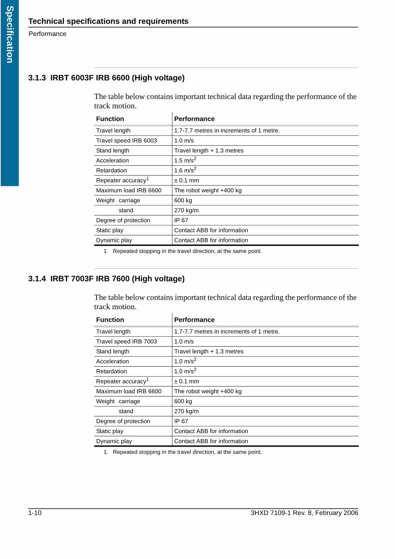
3.1.3 IRBT 6003F IRB 6600 (High voltage)
The table below contains important technical data regarding the performance of the track motion.
3.1.4 IRBT 7003F IRB 7600 (High voltage)
The table below contains important technical data regarding the performance of the track motion.
Function Performance
Travel length 1.7-7.7 metres in increments of 1 metre.
Travel speed IRB 6003 1.0 m/s
Stand length Travel length + 1.3 metres
Acceleration 1.5 m/s2
Retardation 1.6 m/s2
Repeater accuracy1
1. Repeated stopping in the travel direction, at the same point.
± 0.1 mm
Maximum load IRB 6600 The robot weight +400 kg
Weight carriage 600 kg
stand 270 kg/m
Degree of protection IP 67
Static play Contact ABB for information
Dynamic play Contact ABB for information
Function Performance
Travel length 1.7-7.7 metres in increments of 1 metre.
Travel speed IRB 7003 1.0 m/s
Stand length Travel length + 1.3 metres
Acceleration 1.0 m/s2
Retardation 1.0 m/s2
Repeater accuracy1
1. Repeated stopping in the travel direction, at the same point.
± 0.1 mm
Maximum load IRB 6600 The robot weight +400 kg
Weight carriage 600 kg
stand 270 kg/m
Degree of protection IP 67
Static play Contact ABB for information
Dynamic play Contact ABB for information

Technical specifications and requirementsDimensions
3HXD 7109-1 Rev. 8, February 2006 1-11
Sp
ecif
icat
ion
3.2 Dimensions
3.2.1 Length measurement
The table below shows the longest possible travel lengths.
The illustration shows IRBT 4003/6003/7003 from page
IRBT 4003FS/4003S, length measurementThe table shows the value of N in the figure above with different travel lengths.
The signal cable on a Foundry track motion with IRB 4400 and IRB6400R has a maximum length of 30 m between BRB and carriage motor. This means that a floor cable harness results in shorter travel lengths. See the table below.
Floor cable harness length Max. travel length
22 m 7.7 m
Travel length Total length of the stand Quantity N
1.7 m 3 m 2
2.7 m 4 m 3
3.7 m 5 m 4
4.7 m 6 m 5
etc.
503 10001000xN

Technical specifications and requirements
Dimensions
1-12 3HXD 7109-1 Rev. 8, February 2006
Sp
ecification
3.2.2 Width and height measurements
The illustration shows IRBT 4003/6003/7003 from the end-plate.
IRBT 6003S/4003S Compact, width and height measurements
1080
1156
1424,5
372
802.
5
Technical specifications and requirementsLoad on cover plate
3HXD 7109-1 Rev. 8, February 2006 1-13
Sp
ecif
icat
ion
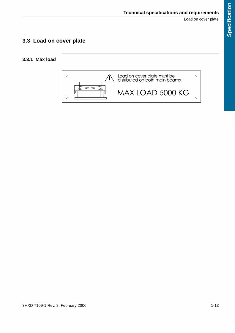
3.3 Load on cover plate
3.3.1 Max load
Technical specifications and requirements
Technical requirements for the robot
1-14 3HXD 7109-1 Rev. 8, February 2006
Sp
ecification
3.4 Technical requirements for the robot
On robots of the type IRB 6400R/IRB 4400 the track motion acts as an integrated seventh axis. In order for it to work satisfactorily the robot’s equipment must comply with a number of minimum requirements.The track motion is designed to work together with the controller of the type S4Cplus, please contact ABB for information about compatibility with other controllers.
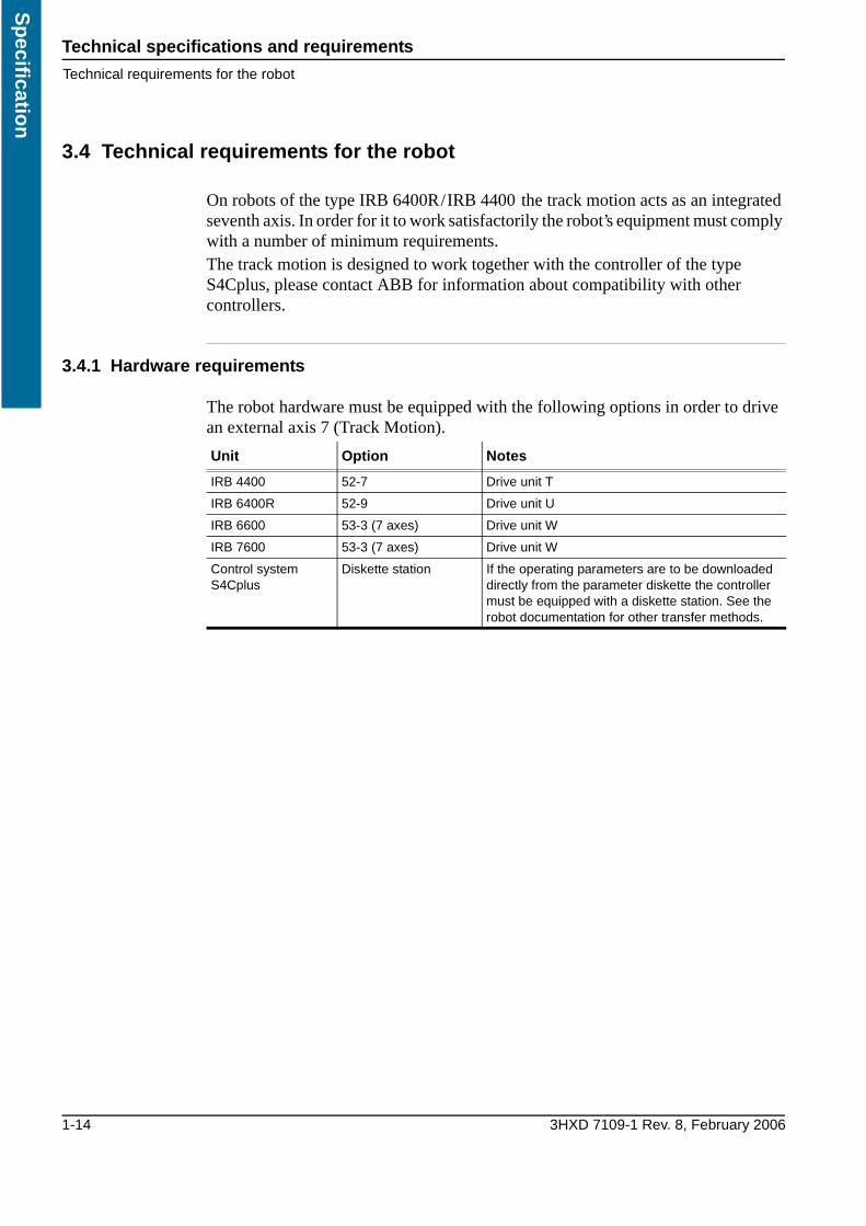
3.4.1 Hardware requirements
The robot hardware must be equipped with the following options in order to drive an external axis 7 (Track Motion).
Unit Option Notes
IRB 4400 52-7 Drive unit T
IRB 6400R 52-9 Drive unit U
IRB 6600 53-3 (7 axes) Drive unit W
IRB 7600 53-3 (7 axes) Drive unit W
Control system S4Cplus
Diskette station If the operating parameters are to be downloaded directly from the parameter diskette the controller must be equipped with a diskette station. See the robot documentation for other transfer methods.
Variants and optionsVariants and options to the IRBT 4003F/6003F/7003F
3HXD 7109-1 Rev. 8, February 2006 1-15
Sp
ecif
icat
ion
4 Variants and options
4.1 Variants and options to the IRBT 4003F/6003F/7003F
4.1.1 Connection cable
The robot’s standard cables can be used to connect the track motion to the controller.
4.1.2 Power cable
The power cable to the seventh axis is 7, 15 or 22 metres long, measured from the connection point in the centre of the track motion.
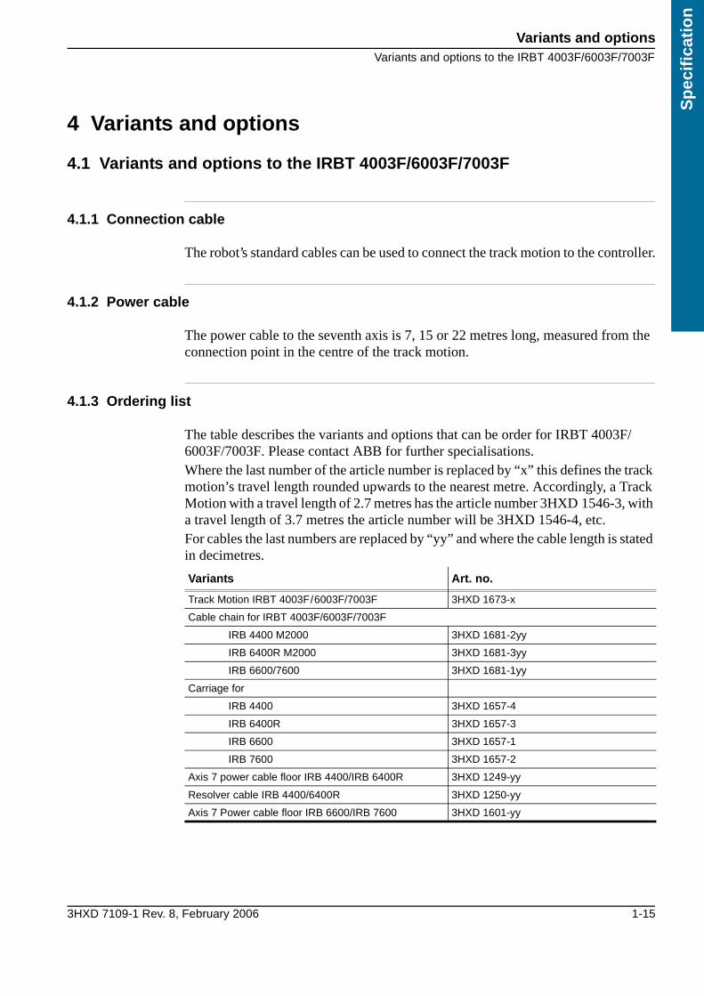
4.1.3 Ordering list
The table describes the variants and options that can be order for IRBT 4003F/6003F/7003F. Please contact ABB for further specialisations.Where the last number of the article number is replaced by “x” this defines the track motion’s travel length rounded upwards to the nearest metre. Accordingly, a Track Motion with a travel length of 2.7 metres has the article number 3HXD 1546-3, with a travel length of 3.7 metres the article number will be 3HXD 1546-4, etc.For cables the last numbers are replaced by “yy” and where the cable length is stated in decimetres.
Variants Art. no.
Track Motion IRBT 4003F/6003F/7003F 3HXD 1673-x
Cable chain for IRBT 4003F/6003F/7003F
IRB 4400 M2000 3HXD 1681-2yy
IRB 6400R M2000 3HXD 1681-3yy
IRB 6600/7600 3HXD 1681-1yy
Carriage for
IRB 4400 3HXD 1657-4
IRB 6400R 3HXD 1657-3
IRB 6600 3HXD 1657-1
IRB 7600 3HXD 1657-2
Axis 7 power cable floor IRB 4400/IRB 6400R 3HXD 1249-yy
Resolver cable IRB 4400/6400R 3HXD 1250-yy
Axis 7 Power cable floor IRB 6600/IRB 7600 3HXD 1601-yy
Variants and options
Variants and options to the IRBT 4003F/6003F/7003F
1-16 3HXD 7109-1 Rev. 8, February 2006
Sp
ecification
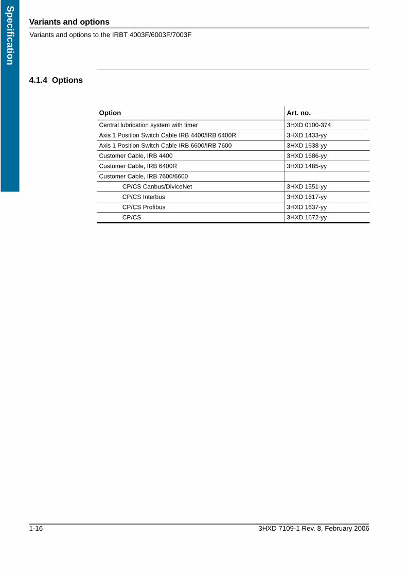
4.1.4 Options
Option Art. no.
Central lubrication system with timer 3HXD 0100-374
Axis 1 Position Switch Cable IRB 4400/IRB 6400R 3HXD 1433-yy
Axis 1 Position Switch Cable IRB 6600/IRB 7600 3HXD 1638-yy
Customer Cable, IRB 4400 3HXD 1686-yy
Customer Cable, IRB 6400R 3HXD 1485-yy
Customer Cable, IRB 7600/6600
CP/CS Canbus/DiviceNet 3HXD 1551-yy
CP/CS Interbus 3HXD 1617-yy
CP/CS Profibus 3HXD 1637-yy
CP/CS 3HXD 1672-yy

3HXD 7109-1 Rev. 8, February 2006 Installation and operation i
Inst
alla
tio
n a
nd
op
erat
ion
Tab 2: Installation and operation1 Unpacking and handling 1
1.1 Lift 11.1.1 Lifting instructions 11.1.2 Lifting the track motion 11.1.3 The lifting zone 1
1.2 Acceptance inspection 21.2.1 Identification 21.2.2 Contents 21.2.3 Inspection 21.2.4 Cleaning 2
1.3 Moving the carriage manually 31.3.1 General 31.3.2 Release the brake on the BRB-box 31.3.3 Release the brake via the drive on the motor. 3
2 Mechanical installation 5
2.1 Foundation 52.1.1 Robustness 52.1.2 Incline 52.1.3 Static loads 52.1.4 Dynamic loads 5
2.2 Preparations 62.2.1 Recommendations for mounting 62.2.2 Hole configuration 62.2.3 Base dimensions 7
2.3 Stand assembly 82.3.1 Procedure 82.3.2 Positioning the stand 92.3.3 Adjusting the level 102.3.4 Assemble the linear guides 102.3.5 Assemble the gear racks 122.3.6 Securing the stand to the foundation 132.3.7 Assemble the cover plates 13
2.4 Assembling the cable channel and robot 142.4.1 Assemble the cable tray 142.4.2 Assemble the robot 14
2.5 Mounting the drive unit 15

Installation and operation ii 3HXD 7109-1 Rev. 8, February 2006
Installatio
n an
d o
peratio
n
3 Electrical installation 17
3.1 The robot’s cable harness 173.1.1 Connection point J1 173.1.2 Terminations on J1 17
3.2 Terminations/Wiring diagram 183.2.1 Introduction 18
3.3 IRB 6600/IRB 7600 M2000, MH DDU W 193.3.1 Wiring diagram 193.3.2 Standard cables 193.3.3 Optional cables 20
3.4 IRB 6400R M2000 213.4.1 Wiring diagram 213.4.2 Standard cables 213.4.3 Optional cables 21
3.5 IRB 4400 M2000 223.5.1 Wiring diagram 223.5.2 Standard cables 223.5.3 Optional cables 22
4 Commissioning 23
4.0.1 Preparations 23
4.1 Configuration of the controller 244.1.1 Load the operating parameters 244.1.2 Commutation offset 244.1.3 Travel length 24
4.2 Lubricating Track Motion 254.2.1 General 254.2.2 Set the timer for the central lubrication system 254.2.3 Functionality test of the Trabon lubrication system 27
4.3 Calibration 294.3.1 Calibrate the track motion 294.3.2 Calibration with a restart 29
4.4 Checking the working area 294.4.1 Check the working area 29
4.5 Check for abnormal wear and noise 304.5.1 Linear guide joints 304.5.2 Gear rack joints 304.5.3 Gear play 304.5.4 Adjust cables and covers 31
Unpacking and handlingLift
3HXD 7109-1 Rev. 8, February 2006 2-1
Inst
alla
tio
n a
nd
op
erat
ion
1 Unpacking and handling
1.1 Lift
1.1.1 Lifting instructions
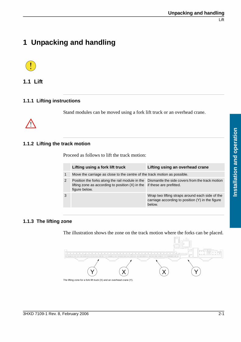
Stand modules can be moved using a fork lift truck or an overhead crane.
1.1.2 Lifting the track motion
Proceed as follows to lift the track motion:
1.1.3 The lifting zone
The illustration shows the zone on the track motion where the forks can be placed.
The lifting zone for a fork lift truck (X) and an overhead crane (Y).
Lifting using a fork lift truck Lifting using an overhead crane
1 Move the carriage as close to the centre of the track motion as possible.
2 Position the forks along the rail module in the lifting zone as according to position (X) in the figure below.
Dismantle the side covers from the track motion if these are prefitted.
3 Wrap two lifting straps around each side of the carriage according to position (Y) in the figure below.
Y XX Y

Unpacking and handling
Acceptance inspection
2-2 3HXD 7109-1 Rev. 8, February 2006
Installatio
n an
d o
peratio
n
1.2 Acceptance inspection
1.2.1 Identification
The identification plates, located by (X), state the carriage type, serial number, delivery date, etc.
Identification plates (X)
1.2.2 Contents
As standard the track motion includes the following on delivery:
• One carriage (with possible adaptor) with the drive unitThe carriage weighs approx.: 600 kg. (+ possible adaptor, 160/193 kg)
• Stand modules and cable chainThe track motion with a travel length greater than 4.7 m are designed with several stand modules interconnected during installation.
• Mounting bolts and guide sleevesMounting bolts with washers and guide sleeves for the robot.
1.2.3 Inspection
Unpack the equipment and check for any visible transport damage. If this is the case, contact ABB.
1.2.4 Cleaning
Before transport the equipment has been protected against rust by a thin film of oil that has been applied before packing. This film of oil must be wiped off before installation.
1 Wipe off any surplus oil using a lintless cloth

Unpacking and handlingMoving the carriage manually
3HXD 7109-1 Rev. 8, February 2006 2-3
Inst
alla
tio
n a
nd
op
erat
ion
1.3 Moving the carriage manually
1.3.1 General
Re-calibration must be carried out if the table is moved manually, see Calibration
1.3.2 Release the brake on the BRB-box
The carriage can be moved manually if necessary by connecting the power and releasing the brake.
1.3.3 Release the brake via the drive on the motor
24V DC can be connected to the motor’s power cable, if there is no voltage supply to the motor.
Low voltage motor
The following instructions apply for a low voltage motor.
High voltage motor
The following instructions apply for a high voltage motor.
1 Press in the brake release button.
1 Connect 24V DC between pin M (0V) and L (+24V) on connector MP.M7 (power cable, 3HXD 1249)
1 Connect 24V DC between pin W (0V) and V (+24V) on connector MP.M7/M8 (power cable, 3HXD 1705)
Unpacking and handling
Moving the carriage manually
2-4 3HXD 7109-1 Rev. 8, February 2006
Installatio
n an
d o
peratio
n

Mechanical installationFoundation
3HXD 7109-1 Rev. 8, February 2006 2-5
Inst
alla
tio
n a
nd
op
erat
ion
2 Mechanical installation
2.1 Foundation
2.1.1 Robustness
The foundation must withstand the static loads caused by the weight of the equipment and the dynamic loads generated by the movement of the carriage and manipulator, see “Foundation” section 2.1.
2.1.2 Incline
The foundation must be designed so that the track motion can be mounted without the incline exceeding 0.5 mm/m in the direction of travel and 0.1 mm/m across this.
2.1.3 Static loads
The table shows the static loads that the foundation must be able to bear.
2.1.4 Dynamic loads
The dynamic loads from the movement of the track motion and manipulatorcan change direction independent of each other. In these instances where loads are added to each other the foundation must be able to bear these combined loads.The maximum dynamic loads for the track motion are:
• (Weight, carriage + Weight, manipulator + Weight extra load) x Acceleration
• See the robot documentation with regard to dynamic loads for the robot.
Load Value
Distributed load, stand 270 kg/M
Movable, in the direction of travel
Manipulator 2400 kg
Carriage 600 kg
Adaptor, (IRB 4400) 160 kg
Permitted extra load
IRB 4400 100 kg
IRB 6400R 300 kg
IRB 6600 400 kg
IRB 7600 700 kg
The track motion should not be used so that the maximum loads from the robot and conveyor are added to each other. If, for example, the carriage is used at maximum speed in one direc-tion the robot should be at a standstill or move in the opposite direction.

Mechanical installation
Preparations
2-6 3HXD 7109-1 Rev. 8, February 2006
Installatio
n an
d o
peratio
n
2.2 Preparations
2.2.1 Recommendations for mounting
Chemical anchor bolts are recommended to secure the track motion to the floor. However, the mounting bolts are not supplied as these must be selected based on the material the foundation is made of.
Mounting bolts Choose mounting bolts so that they:
• Are suitable for the foundation
• Can bear the dynamic loads
• The bolts must be able to bear the combined dynamic loads that can occur when the manipulator and carriage move, see Foundation 2.1.
• Fit in the holes in the stand, Ø24 mm
2.2.2 Hole configuration
The stand's ground plates have holes with a diameter of 24 mm.
Hole configuration
The table shows the value of N in the figure above with different travel lengths.
Travel length Total length of the stand Quantity N
1.7 m 3 m 2
2.7 m 4 m 3
3.7 m 5 m 4
4.7 m 6 m 5
etc.
Mechanical installationPreparations
3HXD 7109-1 Rev. 8, February 2006 2-7
Inst
alla
tio
n a
nd
op
erat
ion
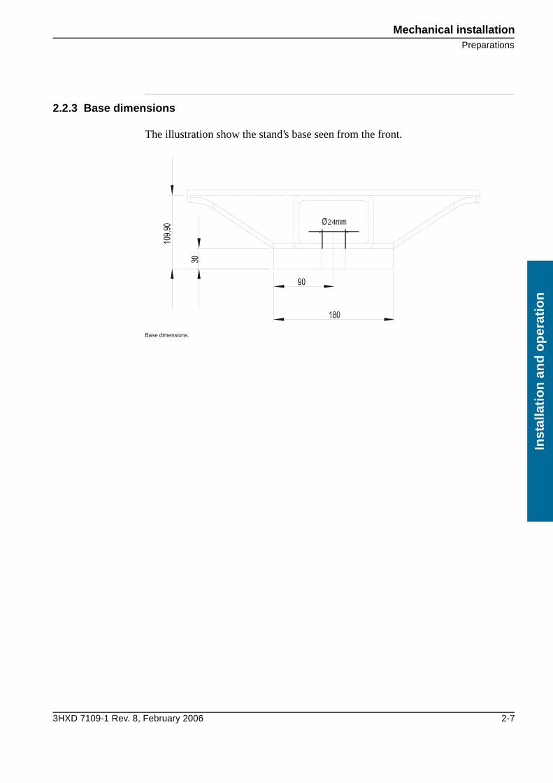
2.2.3 Base dimensions
The illustration show the stand’s base seen from the front.
Base dimensions.
24

Mechanical installation
Stand assembly
2-8 3HXD 7109-1 Rev. 8, February 2006
Installatio
n an
d o
peratio
n
2.3 Stand assembly
2.3.1 Procedure
The track motion should be assembled as set out in the he procedure below. A detailed description of each stage can be found in further on in the manual.
Assembly without fish bolts.
1 Assemble the stand modules according to “Positioning the stand” section 2.3.2.
2 Assemble the linear guides according to“Assemble the linear guides” section 2.3.4.
3 Assemble the gear racks according to “Assemble the gear racks” section 2.3.5.
4 Anchor the stand to the foundation according to “Securing the stand to the foundation” section 2.3.6.
5 Assemble the protective guards and cover plates according to “Assemble the cover plates” section 2.3.7.
6 Assemble the cable tray according to “Assembling the cable channel and robot” section 2.4.
The module’s fish bolts are only required on prefitted modules up to six metres that are to be lifted as a single unit. If the track motion consists of more modules, these should not be assembled using fish bolts, see the illustration below.
Mechanical installationStand assembly
3HXD 7109-1 Rev. 8, February 2006 2-9
Inst
alla
tio
n a
nd
op
erat
ion
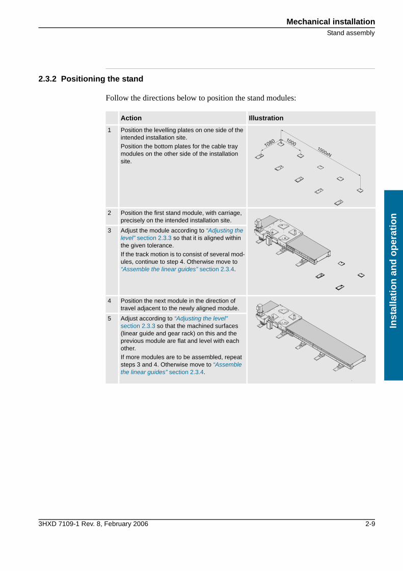
2.3.2 Positioning the stand
Follow the directions below to position the stand modules:
Action Illustration
1 Position the levelling plates on one side of the intended installation site.
Position the bottom plates for the cable tray modules on the other side of the installation site.
2 Position the first stand module, with carriage, precisely on the intended installation site.
3 Adjust the module according to “Adjusting the level” section 2.3.3 so that it is aligned within the given tolerance.
If the track motion is to consist of several mod-ules, continue to step 4. Otherwise move to “Assemble the linear guides” section 2.3.4.
4 Position the next module in the direction of travel adjacent to the newly aligned module.
5 Adjust according to “Adjusting the level” section 2.3.3 so that the machined surfaces (linear guide and gear rack) on this and the previous module are flat and level with each other.
If more modules are to be assembled, repeat steps 3 and 4. Otherwise move to “Assemble the linear guides” section 2.3.4.
1000xN
10001080

Mechanical installation
Stand assembly
2-10 3HXD 7109-1 Rev. 8, February 2006
Installatio
n an
d o
peratio
n
2.3.3 Adjusting the level
First read the information on sid 2-6 and carry out the steps on sid 2-9.
It is recommended to use a laser level in the track motion’s direction of travel and a spirit level across this in order to obtain satisfactory adjustment. Always measure on a machined surface, for example, for the linear guide or gear rack.Follow the directions below to position the beam units:
2.3.4 Assemble the linear guides
First read the information on sid 2-6 and carry out the steps on sid 2-9.Follow the directions below to assemble the linear guide:
The distance between the expansion bolt and the gear wheel guard must be at least 10 mm, see the safety chapter. 2.3.1
Action Illustration
1 Unscrew the locking nut on the level-ling bolt, item 1.
2 Screw the levelling bolts in or out to raise or lower the ground plate in question, item 2.
3 Repeat all round until the module is aligned within the given tolerance.
4 Tighten the locking nut on the levelling bolt, item 1.
2
1
Action Illustration
1 Secure the part of the linear guide to be fitted on the side.
1

Mechanical installationStand assembly
3HXD 7109-1 Rev. 8, February 2006 2-11
Inst
alla
tio
n a
nd
op
erat
ion
2 Assemble the linear guide on the underside, fitting the bolts loosely at this stage.
3 Push forward the carriage so that the first ball element overlaps half of the joint. The carriage can be moved manually if 24 VDC is con-nected to the motor, see “Moving the carriage manually” section 1.3.
4 Push the carriage forwards, successively tightening the linear guides on the underside.Tightening torque: 50Nm.
If more sections are to be assembled, repeat step 1. Otherwise move to “Assemble the gear racks” section 2.3.5.
Action Illustration
2
3

Mechanical installation
Stand assembly
2-12 3HXD 7109-1 Rev. 8, February 2006
Installatio
n an
d o
peratio
n
2.3.5 Assemble the gear racks
First read the information on sid 2-6 and carry out the steps on sid 2-9–sid 2-10.Follow the directions below to assemble the gear racks:
Action Illustration
1 Lay out the section of the gear rack to be assembled against the support edge, and bolt loosely in position.
2 Check using the supplied teeth-meshing gauge that the joints on the laid gear rack proved a smooth transition.
If the teeth on the test piece and the gear rack do not mesh, continue with step 3. Otherwise go directly to step 6.
3 If the teeth on the test piece and the gear rack do not mesh, loosen the bolts on the prefitted gear racks.
4 Adjust the transition by using the play on the mountings on the prefitted gear racks.
5 Secure the prefitted gear racks.Tightening torque: 50Nm.
6 Secure the assembled gear rack section.Tightening torque: 50Nm.
If more sections are to be assembled, repeat step 1. Otherwise move to “Securing the stand to the foundation” section 2.3.6.
1
2

Mechanical installationStand assembly
3HXD 7109-1 Rev. 8, February 2006 2-13
Inst
alla
tio
n a
nd
op
erat
ion
2.3.6 Securing the stand to the foundation
First read the information on sid 2-6 and carry out the steps on sid 2-9–sid 2-12.Follow the directions below to secure the track motion to the foundation:
2.3.7 Assemble the cover plates
First read the information on sid 2-6 and carry out the steps on sid 2-9–sid 2-13.Follow the directions below to assemble the cover plates:
Action
1 Check that none of the levelling bolts on the track’s ground plates are hanging in the air or that the distance between the levelling bolts and the top edge of the ground plates is at least 10 mm.
Adjust if necessary according to “Adjusting the level” section 2.3.3.
2 Move the carriage manually and check using the spirit level along the entire track, both in the direction of travel and across it.
The carriage can be moved manually if 24 VDC is connected to the motor, see section 1.3.
Adjust if necessary according to “Adjusting the level” section 2.3.3.
3 Drill holes for the mounting bolts through the ground plates' mounting holes (max. Ø24).
The holes vary depending on the chosen mounting method, see“Recommendations for mount-ing” section 2.2.1
4 Secure the track motion to the foundation using an appropriate anchoring method.
The anchoring method must be adapted to the foundation and the dynamic loads that the track motion generates, see“Foundation” section 2.1 and “Recommendations for mounting” section 2.2.1.
5 Continue to “Assemble the cover plates” section 2.3.7.
Action Illustration
1 Assemble the end plates on the track motion’s short ends, see item 1.
2 Assemble the cover plate, see item 2. (Fitted on all track motions with joints). 2
1
1

Mechanical installation
Assembling the cable channel and robot
2-14 3HXD 7109-1 Rev. 8, February 2006
Installatio
n an
d o
peratio
n
2.4 Assembling the cable channel and robot
2.4.1 Assemble the cable tray
First read the information on sid 2-6 and carry out the steps on sid 2-9–sid 2-13.Follow the directions below to position the cable tray and levelling plates:
2.4.2 Assemble the robot
Depending on how the order was made the manipulator should be assembled in one of following two positions:
• InLineNeutral position for axis 1 aligned with the track motion's direction of travel (2).
• 90°Neutral position for axis 1 aligned 90° with the track motion's direction of travel (1)
Manipulator assembly positions, InLine (2) and 90° (1).
Action Illustration
1 Bolt the cable tray’s guide plates on to the plates.
Knock gently on the side if the position of the holes do not align.
2 If the travel length of the completed track motion is 5.7 metres or more a raised support for the cable chain should be placed in the last cable tray.
The raised support should be fitted on the mid-most ground plates (with an odd number of ground plates), or one the closest subsequent ground plate in the direction of travel (with an even number).
1
2
Travel direction
1 2

Mechanical installationMounting the drive unit
3HXD 7109-1 Rev. 8, February 2006 2-15
Inst
alla
tio
n a
nd
op
erat
ion
2.5 Mounting the drive unit
Very important that the gear is align with the gear rack.
1 The machined heel on the drive unit shall be placed on the machined heel on the carriage.
Use MC6S-M10×60 (12.9) (6 pcs) and lubricate the thread and under the screw head with moly-cote 1000, tighten them with torque 70Nm.
2 Adjust the play with the two screws A and B below (M20×1.5).
Grease the screws with molycote grease.
3 First press the motor inwards with screw B until you have the right play ± 0.1 mm.
See the technical report for tightening torque (approx. 170-190 Nm).
4 Tighten the screw A with 60 Nm.
A B

Mechanical installation
Mounting the drive unit
2-16 3HXD 7109-1 Rev. 8, February 2006
Installatio
n an
d o
peratio
n

Electrical installationThe robot’s cable harness
3HXD 7109-1 Rev. 8, February 2006 2-17
Inst
alla
tio
n a
nd
op
erat
ion
3 Electrical installation
3.1 The robot’s cable harness
The robot’s cable harness is sufficiently long for installation in one of the two possible positions on the carriage. Any surplus should be placed in a coil on the floor, depending on the local conditions.
3.1.1 Connection point J1
The cable harness that normally connects the controller with the manipulator and carriage is connected to the track motion’s connection point, J1. Ensure there is space available under connection plate.
Connection point J1
3.1.2 Terminations on J1
The following terminations can be found on the track motion’s connection point, J1:
• Axis 7 Power CableA Harting connector for the track motion's power supply.
• Power Cable axis 1–6A Harting connector for the manipulator's power supply.
• Signal CableA Burndy connector for the manipulator's control signals.
• Customer CableTerminal post for connection of option cables.
• Signal cable axis 7Burndy connector for the track motion's signals.
Make sure the cable harness cannot come into contact with any moving parts.
J1

Electrical installation
Terminations/Wiring diagram
2-18 3HXD 7109-1 Rev. 8, February 2006
Installatio
n an
d o
peratio
n
3.2 Terminations/Wiring diagram
3.2.1 Introduction
The wiring diagram below describes the connections between the controller, manipulator and Track Motion.The position numbers in the table refer to the positions in the illustration above. Cables marked with (R) in the illustration are supplied with the robot.Where the last numbers of the article number are replaced by “yy” in the table, the cable length should be stated in decimetres (-70 for 7 metres, -150 for 15 metres and -220 for 22 metres)
The abbreviation MH used in the following sections stands for: Material Handling.
Electrical installationIRB 6600/IRB 7600 M2000, MH DDU W
3HXD 7109-1 Rev. 8, February 2006 2-19
Inst
alla
tio
n a
nd
op
erat
ion
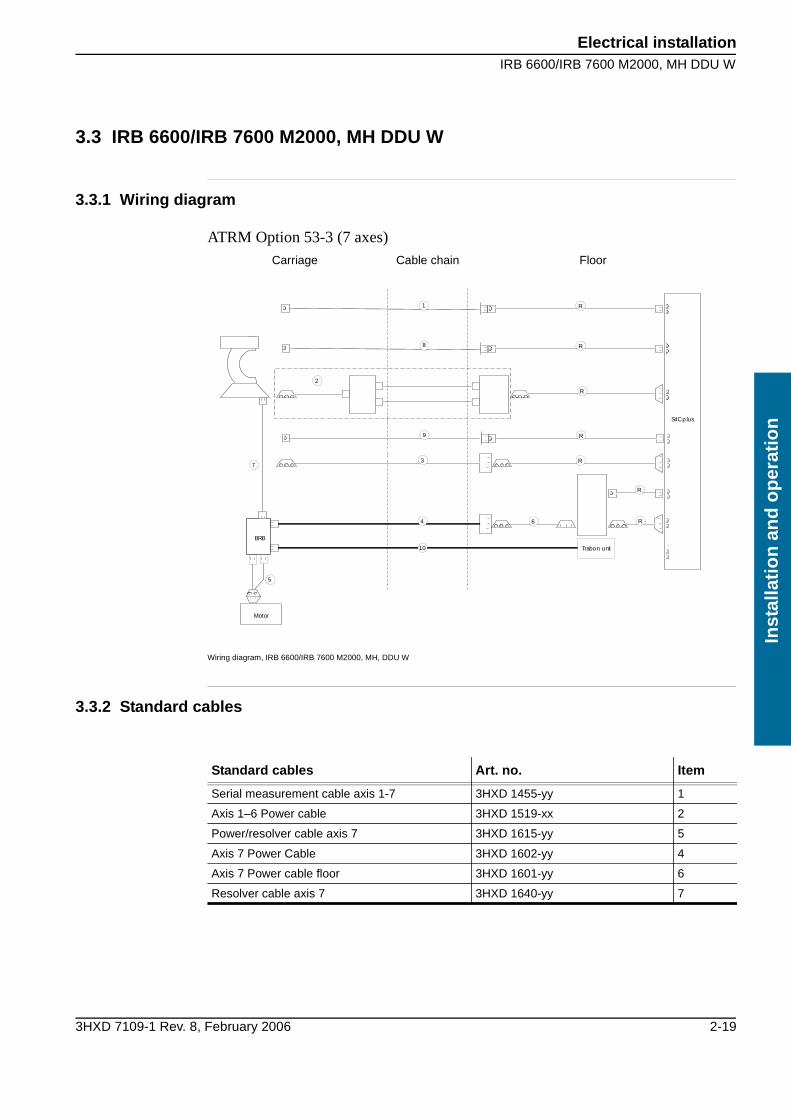
3.3 IRB 6600/IRB 7600 M2000, MH DDU W
3.3.1 Wiring diagram
ATRM Option 53-3 (7 axes)
Wiring diagram, IRB 6600/IRB 7600 M2000, MH, DDU W
3.3.2 Standard cables
Carriage Cable chain Floor
S4Cplus
R
3
4 6
R
R
R
R
2
7
S4Cplus
Motor
BRB
5
R1
8
R9
10 Trabon unit
Standard cables Art. no. Item
Serial measurement cable axis 1-7 3HXD 1455-yy 1
Axis 1–6 Power cable 3HXD 1519-xx 2
Power/resolver cable axis 7 3HXD 1615-yy 5
Axis 7 Power Cable 3HXD 1602-yy 4
Axis 7 Power cable floor 3HXD 1601-yy 6
Resolver cable axis 7 3HXD 1640-yy 7

Electrical installation
IRB 6600/IRB 7600 M2000, MH DDU W
2-20 3HXD 7109-1 Rev. 8, February 2006
Installatio
n an
d o
peratio
n
3.3.3 Optional cables
Optional cables Art. no. Item
Position Switch Cable axis 1 3HXD 1638-yy 8
Position Switch Cable axis 2-3 3HXD 1691-yy 9
Cable central lubrication 3HXD 1628-yy 10
Robot customer cable harness
CANBUS/DeviceNet 3HXD 1551-yy 3
INTERBUS 3HXD 1617-yy 3
PROFIBUS 3HXD 1637-yy 3
Parallel 3HXD 1672-yy 3
Electrical installationIRB 6400R M2000
3HXD 7109-1 Rev. 8, February 2006 2-21
Inst
alla
tio
n a
nd
op
erat
ion
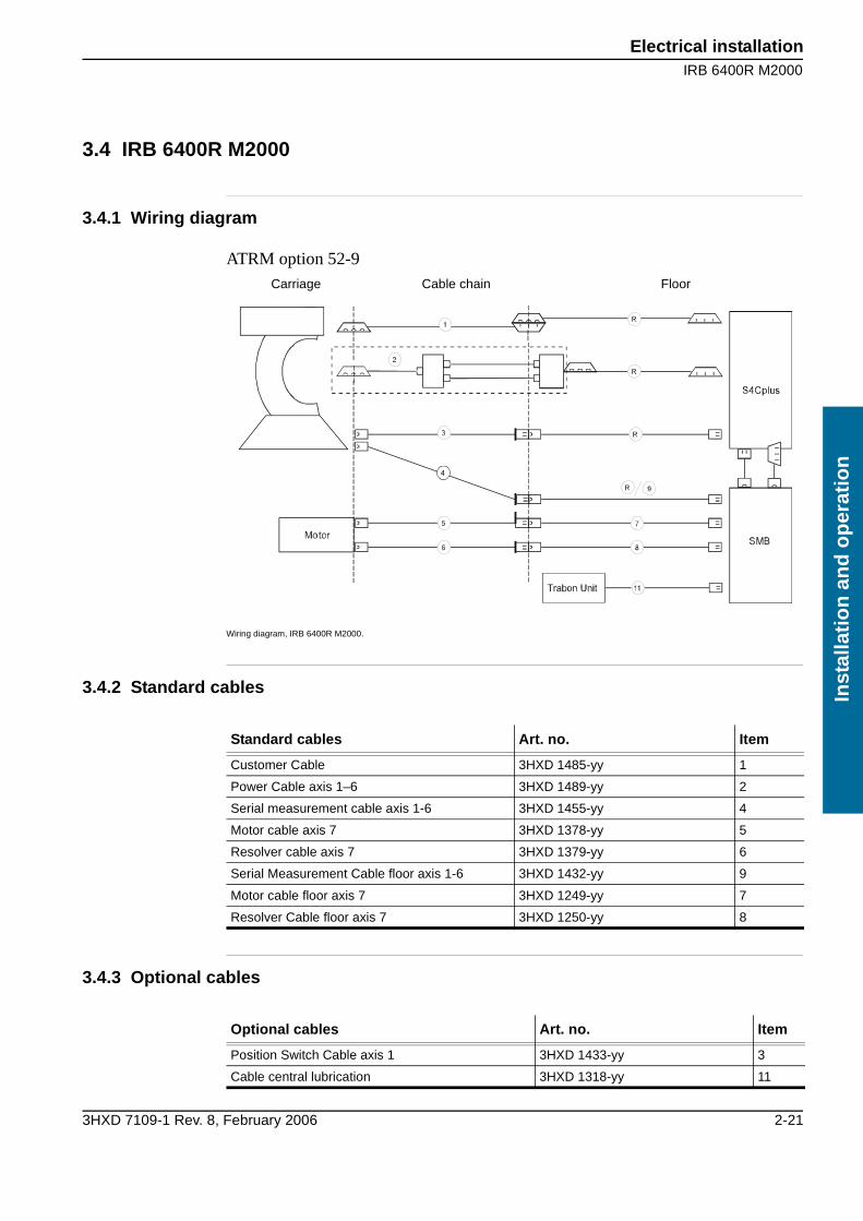
3.4 IRB 6400R M2000
3.4.1 Wiring diagram
ATRM option 52-9
Wiring diagram, IRB 6400R M2000.
3.4.2 Standard cables
3.4.3 Optional cables
Carriage Cable chain Floor
Standard cables Art. no. Item
Customer Cable 3HXD 1485-yy 1
Power Cable axis 1–6 3HXD 1489-yy 2
Serial measurement cable axis 1-6 3HXD 1455-yy 4
Motor cable axis 7 3HXD 1378-yy 5
Resolver cable axis 7 3HXD 1379-yy 6
Serial Measurement Cable floor axis 1-6 3HXD 1432-yy 9
Motor cable floor axis 7 3HXD 1249-yy 7
Resolver Cable floor axis 7 3HXD 1250-yy 8
Optional cables Art. no. Item
Position Switch Cable axis 1 3HXD 1433-yy 3
Cable central lubrication 3HXD 1318-yy 11

Electrical installation
IRB 4400 M2000
2-22 3HXD 7109-1 Rev. 8, February 2006
Installatio
n an
d o
peratio
n
3.5 IRB 4400 M2000
3.5.1 Wiring diagram
ATRM option 52-7
Wiring diagram, IRB 4400 M99-M2000.
3.5.2 Standard cables
3.5.3 Optional cables
Carriage Cable chain Floor
Standard cables Art. no. Item
Customer cable 3HXD 1486-yy 1
Power Cable axis 1–6 3HXD 1487-yy 2
Serial measurement cable axis 1-6 3HXD 1455-yy 4
Resolver cable axis 7 3HXD 1378-yy 5
Axis 7 Power Cable 3HXD 1379-yy 6
Axis 7 Power cable floor 3HXD 1249-yy 7
Resolver Cable floor axis 7 3HXD 1250-yy 8
Serial Measurement Cable floor axis 1-6 3HXD 1432-yy 9
Axis 7 Power cable floor 3HXD 1253-yy 10
Optional cables Art. no. Item
Position Switch Cable axis 1 3HXD 1433-yy 3
Cable central lubrication 3HXD 1318-yy 11
CommissioningIRB 4400 M2000
3HXD 7109-1 Rev. 8, February 2006 2-23
Inst
alla
tio
n a
nd
op
erat
ion
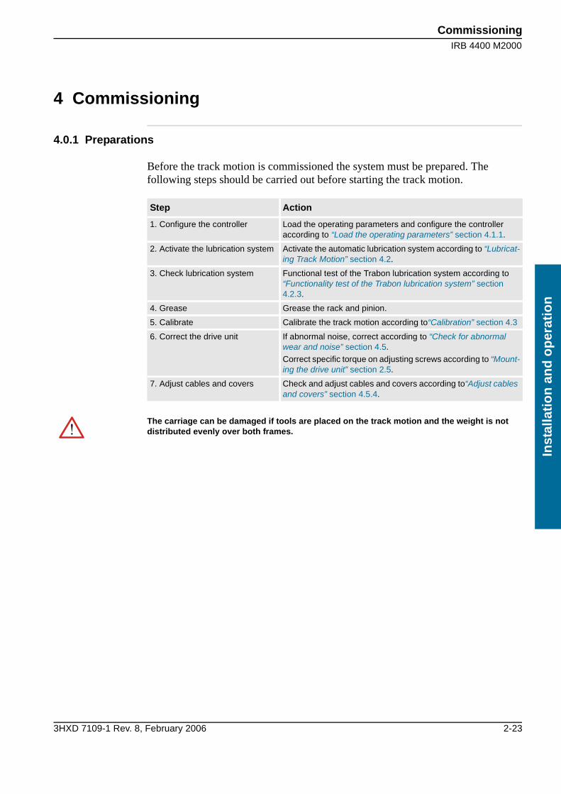
4 Commissioning
4.0.1 Preparations
Before the track motion is commissioned the system must be prepared. The following steps should be carried out before starting the track motion.
Step Action
1. Configure the controller Load the operating parameters and configure the controller according to “Load the operating parameters” section 4.1.1.
2. Activate the lubrication system Activate the automatic lubrication system according to “Lubricat-ing Track Motion” section 4.2.
3. Check lubrication system Functional test of the Trabon lubrication system according to “Functionality test of the Trabon lubrication system” section 4.2.3.
4. Grease Grease the rack and pinion.
5. Calibrate Calibrate the track motion according to“Calibration” section 4.3
6. Correct the drive unit If abnormal noise, correct according to “Check for abnormal wear and noise” section 4.5.
Correct specific torque on adjusting screws according to “Mount-ing the drive unit” section 2.5.
7. Adjust cables and covers Check and adjust cables and covers according to“Adjust cables and covers” section 4.5.4.
The carriage can be damaged if tools are placed on the track motion and the weight is not distributed evenly over both frames.
Commissioning
Configuration of the controller
2-24 3HXD 7109-1 Rev. 8, February 2006
Installatio
n an
d o
peratio
n
4.1 Configuration of the controller
4.1.1 Load the operating parameters
The track motion must be defined in the system before starting with the operating parameters, which can be found on the supplied diskette.A description of how to load parameters from diskette to the controller can be found in the robot documentation.Proceed as follows to load the operating parameters:
4.1.2 Commutation offset
The IRBT commutation offset is a fixed value that is set at the factory. All IRBT track motions have the same offset value and this does not need to be changed.
4.1.3 Travel length
The different travel lengths’ working areas are defined based on the calibration mark. The travel length is set to maximum in the parameter file for the ordered travel length.
1 Select the file: Add New Parameters
2 Load the file T6003S.cfg respective T4003S.cfg
CommissioningLubricating Track Motion
3HXD 7109-1 Rev. 8, February 2006 2-25
Inst
alla
tio
n a
nd
op
erat
ion
4.2 Lubricating Track Motion
4.2.1 General
The central lubrication system is positioned outside of the track motion and the lubricant is fed, via a hose in the cable chain, to the distribution unit on the carriage.
4.2.2 Set the timer for the central lubrication system
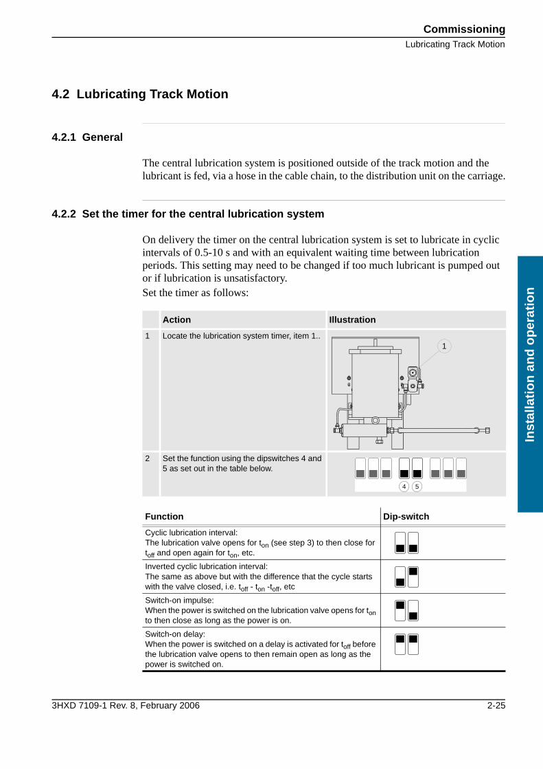
On delivery the timer on the central lubrication system is set to lubricate in cyclic intervals of 0.5-10 s and with an equivalent waiting time between lubrication periods. This setting may need to be changed if too much lubricant is pumped out or if lubrication is unsatisfactory.Set the timer as follows:
Action Illustration
1 Locate the lubrication system timer, item 1..
2 Set the function using the dipswitches 4 and 5 as set out in the table below.
Function Dip-switch
Cyclic lubrication interval:The lubrication valve opens for ton (see step 3) to then close for toff and open again for ton, etc.
Inverted cyclic lubrication interval:The same as above but with the difference that the cycle starts with the valve closed, i.e. toff - ton -toff, etc
Switch-on impulse:When the power is switched on the lubrication valve opens for ton to then close as long as the power is on.
Switch-on delay:When the power is switched on a delay is activated for toff before the lubrication valve opens to then remain open as long as the power is switched on.
1
4 5
Commissioning
Lubricating Track Motion
2-26 3HXD 7109-1 Rev. 8, February 2006
Installatio
n an
d o
peratio
n
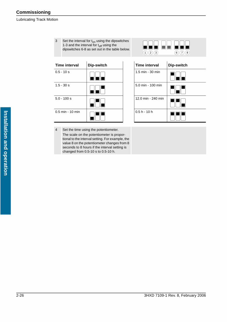
3 Set the interval for ton using the dipswitches 1-3 and the interval for toff using the dipswitches 6-8 as set out in the table below.
Time interval Dip-switch Time interval Dip-switch
0.5 - 10 s 1.5 min - 30 min
1.5 - 30 s 5.0 min - 100 min
5.0 - 100 s 12.0 min - 240 min
0.5 min - 10 min 0.5 h - 10 h
4 Set the time using the potentiometer.
The scale on the potentiometer is propor-tional to the interval setting. For example, the value 8 on the potentiometer changes from 8 seconds to 8 hours if the interval setting is changed from 0.5-10 s to 0.5-10 h.
1 2 3 6 7 8

CommissioningLubricating Track Motion
3HXD 7109-1 Rev. 8, February 2006 2-27
Inst
alla
tio
n a
nd
op
erat
ion
4.2.3 Functionality test of the Trabon lubrication system
Perform the functionality test of the Trabon lubrication system when the Track Motion is completely set up and power and air supply is connected.
System overview
chec
k po
ints
.wm
f
Lubrication system overview
Pos. Description Pos. Description
1 Divider connection 4 Indicator pin
2 Lubrication point 5 Oil brush
3 Pump connection
Commissioning
Lubricating Track Motion
2-28 3HXD 7109-1 Rev. 8, February 2006
Installatio
n an
d o
peratio
n
Instruction
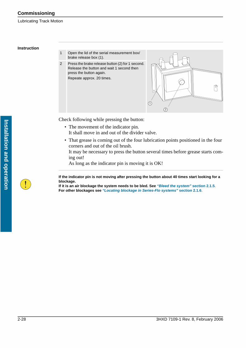
Check following while pressing the button:
• The movement of the indicator pin.It shall move in and out of the divider valve.
• That grease is coming out of the four lubrication points positioned in the four corners and out of the oil brush.It may be necessary to press the button several times before grease starts com-ing out!As long as the indicator pin is moving it is OK!
1 Open the lid of the serial measurement box/ brake release box (1).
2 Press the brake release button (2) for 1 second. Release the button and wait 1 second then press the button again.
Repeate approx. 20 times.
If the indicator pin is not moving after pressing the button about 40 times start looking for a blockage.If it is an air blockage the system needs to be bled. See “Bleed the system” section 2.1.5. For other blockages see “Locating blockage in Series-Flo systems” section 2.1.6.

CommissioningCalibration
3HXD 7109-1 Rev. 8, February 2006 2-29
Inst
alla
tio
n a
nd
op
erat
ion
4.3 Calibration
4.3.1 Calibrate the track motion
Before the robot system can be used the resolvers need to be calibrated.Perform calibrations according to the instruction below.
4.3.2 Calibration with a restart
A robot system that uses a serial measurement system does not need to be calibrated before a restart, as the robot system automatically monitors the position of the robot in the working area.
4.4 Checking the working area
4.4.1 Check the working area
Run the system manually using the joystick and check that:
• It can be run in both directions
• Both end positions are reached
Action Illustration
1 Calibrate according to the instructions in the robot documentation.
2 Check that the carriage stops exactly on the calibration mark.
3 Save the system parameters according to the instructions in the robot documentation.
The track motion does not need to be calibrated with a restart. The resolvers only need to be calibrated when commissioning the system.
Commissioning
Check for abnormal wear and noise
2-30 3HXD 7109-1 Rev. 8, February 2006
Installatio
n an
d o
peratio
n
4.5 Check for abnormal wear and noise
In the event of abnormal noise when the track motion is commissioned this may be due to incorrect assembly of the linear guides or gear racks or the gear play’s meshing pressure needs to be adjusted.
4.5.1 Linear guide joints
Check and adjust the linear guides joints if necessary according to “Assemble the linear guides” section 2.3.4.
4.5.2 Gear rack joints
Check and adjust the gear racks joints if necessary according to “Assemble the gear racks” section 2.3.5.
4.5.3 Gear play
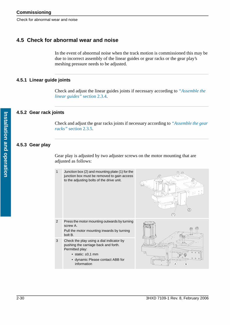
Gear play is adjusted by two adjuster screws on the motor mounting that are adjusted as follows:
1 Junction box (2) and mounting plate (1) for the junction box must be removed to gain access to the adjusting bolts of the drive unit.
2 Press the motor mounting outwards by turning screw A.
Pull the motor mounting inwards by turning bolt B.
3 Check the play using a dial indicator by pushing the carriage back and forth.Permitted play:
• static: ±0,1 mm
• dynamic Please contact ABB for information A B

CommissioningCheck for abnormal wear and noise
3HXD 7109-1 Rev. 8, February 2006 2-31
Inst
alla
tio
n a
nd
op
erat
ion
4.5.4 Adjust cables and covers
Perform the following adjustments:
1 After transportation and set-up the pinion cover (1) may need some adjusting. Otherwise it may be in contact with the pinion and cause noise and vibra-tion.
If noise:
• Adjust pinion cover before start-up.
2 Adjust cables and covers:
• If the cover for the cable chain is used, make sure no risk of collision is possible and that they are well tightened
3 Make sure all cables are well tightened and no risk for premature ware against plates or additional equipments.
• Make sure that cables from cable chain to carriage are well strapped.
• Make sure no floor cables are in risk of collision with moving parts.
1
Commissioning
Check for abnormal wear and noise
2-32 3HXD 7109-1 Rev. 8, February 2006
Installatio
n an
d o
peratio
n
3HXD 7109-1 Rev. 8, February 2006 Maintenance i
Mai
nte
nan
ce
Tab 3: Maintenance1 Maintenance intervals 1
1.1 Routine checks and preventive maintenance 11.1.1 Maintenance chart 1
2 Maintenance instructions 3
2.1 Mechanical maintenance 32.1.1 Lubrication of the ball element and rack 32.1.2 Inspecting the central lubrication system 32.1.3 Filling the central lubrication system 42.1.4 Cleaning and lubrication of the gear racks 52.1.5 Bleed the system 62.1.6 Locating blockage in Series-Flo systems 72.1.7 Cleaning the linear guides 152.1.8 Check ball element tightening torque 162.1.9 Gearbox 16
2.2 Electrical maintenance 172.2.1 Inspection of electrical operations 172.2.2 Check the emergency stop 172.2.3 Inspecting the cabling 172.2.4 Check the connectors 172.2.5 Inspection of the cable chain 172.2.6 Inspection of the junction boxes 182.2.7 Inspection of the drive motor 182.2.8 Backup battery 18
3 Spare parts 19
3.1 Spare parts independent of length 193.1.1 Drive unit IRBT 4003F/6003F/7003F 193.1.2 Carriage IRBT 4003F/6003F/7003F 203.1.3 Central lubrication system (central unit) 213.1.4 Central lubrication system (carriage) 22
3.2 Spare parts dependent on length 233.2.1 Cable chain 233.2.2 Cable tray 233.2.3 Stand 24
3.3 Cables 253.3.1 Cable lengths 25

Maintenance ii 3HXD 7109-1 Rev. 8, February 2006
Main
tenan
ce

Maintenance intervalsRoutine checks and preventive maintenance
3HXD 7109-1 Rev. 8, February 2006 3-1
Mai
nte
nan
ce
1 Maintenance intervals
1.1 Routine checks and preventive maintenance
1.1.1 Maintenance chart
The track motion is designed to need a minimum of maintenance. However, routine checks and preventive maintenance always need to be carried out at regular inter-vals.The maintenance chart describes the routine maintenance and routine checks in chronological order.
Interval Part Maintenance More Info.
Every 100 km (60 miles) or at least once a month
Ball element Lubricate sid 3-3
Gear racks Clean and lubricate (if there is no auto-matic lubrication system)
sid 3-5
Each month Automatic lubrication system
Check the level sid 3-3
Electrical operation Check all electrical operations sid 3-17
Cables and connectors Check visible cables sid 3-17
Cable chain Check the visible cable chain sid 3-17
Junction boxes Check sid 3-18
Drive motor Check sid 3-18
Every third month
Linear guides Clean if necessary. sid 3-15
Ball element Check tightening torque sid 3-16
Every 5000 operating hours
Gearbox Change the oil sid 3-15
Every 5 years Backup battery Change the battery with signs of discharge
sid 3-18
Maintenance intervals
Routine checks and preventive maintenance
3-2 3HXD 7109-1 Rev. 8, February 2006
Main
tenan
ce

Maintenance instructionsMechanical maintenance
3HXD 7109-1 Rev. 8, February 2006 3-3
Mai
nte
nan
ce
2 Maintenance instructions
2.1 Mechanical maintenance
2.1.1 Lubrication of the ball element and rack
If there is no automatic lubrication system on the track motion the ball element must be lubricated manually.Lubricate the ball element until the grease is forced out of the end seals, approx: 4.7 cm³ (1.85 in³).Use ball element grease as set out in NLGI 2, for example:
2.1.2 Inspecting the central lubrication system
If the track motion is equipped with an automatic lubrication system the level of the lubricant should be checked once a month, even if the system should apply the lubri-cant equally over a longer period.Check the lubricant level in the central system as follows:
Manufacturer Lubricant
Shell Alvania WR2
Action Illustration
1 Localise the lubrication system.
2 Check the level in the transparent lubri-cant tank. If the lubricant has been used, fill according to .
1

Maintenance instructions
Mechanical maintenance
3-4 3HXD 7109-1 Rev. 8, February 2006
Main
tenan
ce
2.1.3 Filling the central lubrication system
When the lubricant in the central lubrication system has run out, new lubricant should be added as follows:
• The tank holds 2.71 kg (6 Lb Cyl)
Use ball element grease as set out in NLGI 1, for example:
Action Illustration
1 Connect the supplied filling nipple at position 1
2 Fill with lubricant as set out in the specification below.
Manufacturer Lubricant
Q8 Q8 Rembrandt EP1
Mobil Mobilux EP1
1

Maintenance instructionsMechanical maintenance
3HXD 7109-1 Rev. 8, February 2006 3-5
Mai
nte
nan
ce
2.1.4 Cleaning and lubrication of the gear racks
Clean the gear racks once a month. If there is no automatic lubrication system on the track motion the gear racks must be lubricated manually using one of the following lubricants:
Action Illustration
1 Gear rack
Manufacturer Lubricant
OPTIMOL VISCOGEN EPL
BP MOG
Statoil ESL10
Mobiloil Mobiltac 81
Texaco Texclade
1

Maintenance instructions
Mechanical maintenance
3-6 3HXD 7109-1 Rev. 8, February 2006
Main
tenan
ce
2.1.5 Bleed the system
Note!If the steps below do not make any change start looking for other blockage than air trapped in the system. See .
Action Info/Illustration
1 Disconnect the hose between the pump and the divider valve at the pump connection.
See Fig. 1
2 Press the brake release button in the SMB/BRB for 1 second. Release the button and wait 1 second then press the button again.Keep repeating until nothing but grease comes out of the hose.
3 Reconnect the hose to the pump connection and disconnect it at the divider connection.Repeat step 2 above.
See Fig. 1
4 Hook up a manual pump to the divider valve and slowly pump in grease, compatible with the grease in the lubrication system.Keep pumping until the indicator pin starts moving in and out of the divider valve.
See Fig. 1
5 Reconnect the hose to the divider valve. See Fig. 1
6 Press the brake release button in the SMB/BRB for 1 second. Release the button and wait 1 second then press the button again.Repeat until the indicator pin starts moving in and out of the divider valve.
chec
k po
ints
.wm
f
Fig. 1 Lubrication system overview
Item Description Item Description
1 Divider connection 4 Indicator pin
2 Lubrication point 5 Oil brush
3 Pump connection
Maintenance instructionsMechanical maintenance
3HXD 7109-1 Rev. 8, February 2006 3-7
Mai
nte
nan
ce
2.1.6 Locating blockage in Series-Flo systems
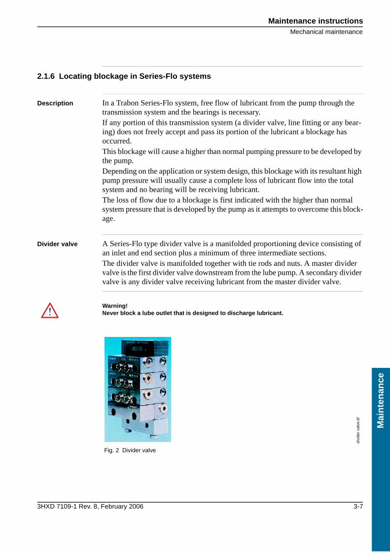
Description In a Trabon Series-Flo system, free flow of lubricant from the pump through the transmission system and the bearings is necessary.If any portion of this transmission system (a divider valve, line fitting or any bear-ing) does not freely accept and pass its portion of the lubricant a blockage has occurred.This blockage will cause a higher than normal pumping pressure to be developed by the pump.Depending on the application or system design, this blockage with its resultant high pump pressure will usually cause a complete loss of lubricant flow into the total system and no bearing will be receiving lubricant.The loss of flow due to a blockage is first indicated with the higher than normal system pressure that is developed by the pump as it attempts to overcome this block-age.
Divider valve A Series-Flo type divider valve is a manifolded proportioning device consisting of an inlet and end section plus a minimum of three intermediate sections.The divider valve is manifolded together with tie rods and nuts. A master divider valve is the first divider valve downstream from the lube pump. A secondary divider valve is any divider valve receiving lubricant from the master divider valve.
Warning!Never block a lube outlet that is designed to discharge lubricant.
divi
der
valv
e.tif
Fig. 2 Divider valve

Maintenance instructions
Mechanical maintenance
3-8 3HXD 7109-1 Rev. 8, February 2006
Main
tenan
ce
Locating blockage
If any blockage exists in a Trabon Series-Flo system it is caused by one of the fol-lowing reasons:
• Crushed transmission line in the system
• Blocked bearing in the system
• Improperly drilled fitting in the system
• Blocked divider valve in the system
A blockage will be centrally signalled by a pressure gauge, pressure switch, control-ler or by the pump relief indicator, exhausting lubricant. Before proceeding as out-lined make a visual inspection of the system and check for crushed lines or improper divider valve installation. Verify that each divider valve outlet required to discharge lubricant can do so and that no pipe plugs have been installed in an outlet designed to serve bearing or another divider valve.
Inte
rmed
iate
val
ve.w
mf
Fig. 3 Intermediate valve & subplate section
Item Description Item Description
1 Piston enclosure plug 5 Indicator port
2 Enclosure plug gasket 6 Plug
3 Piston 7 Check valve
4 O-rings
All servicing and disassembling should be carried out under the cleanest conditions possible.
Use filtered lubricant only!
Note!Dirt and foreign material are the worst enemies of any lubricating system!

Maintenance instructionsMechanical maintenance
3HXD 7109-1 Rev. 8, February 2006 3-9
Mai
nte
nan
ce
Procedure
Step 1
Step 2 Master divider valve equipped with performance indicator:
1 Use a manual pump with gauge. Fill the pump with clean, filtered lubricant common to the system.
2 Connect the manual pump into the inlet of the master divider valve and slowly operate the pump. If the system will not cycle freely below 1,500 PSI, see step 2.
1 With a manual pump connected to the master divider valve as outlined in step 1, raise pressure to 2,000 PSI, the indicators in the indicator ports will signal the location of the blockage.
An indicator in the up position indicates pressure is in that outgoing line and signals the block-age is in the area being served from this outlet, as shown in Fig. 4. See step 3.
2 If no indicator pins are protruding, the blockage is in the master divider valve.
Loca
ting
bloc
kage
.wm
f
Fig. 4 Locating blockage with hand pump
Item Description Item Description
1 Hand pump 4 Secondary divider valve
2 Indicator pin up 5 Lube outlets
3 Master divider valve

Maintenance instructions
Mechanical maintenance
3-10 3HXD 7109-1 Rev. 8, February 2006
Main
tenan
ce
Master divider valve without performance indicators:
If testing in step 2 indicates a blockage in the master divider valve, this divider valve must be disassembled and cleaned. See step 5 for instructions on correct procedure.
1 With a manual pump connected to the master divider valve as outlined in step 1, raise pressure to 2,000 PSI.
2 Remove one at a time each indicator port plug and attempt to operate the manual pump after each plug is removed.
Do not exceed 2,000 PSI.
If pressure drops and master cycles freely after an indicator port plug is removed then the blockage is downstream in the area that is being served from that outlet. See step 3.
3 If all indicator port plugs are removed and master will not cycle, the blockage is in this divider valve.
When indicator port plug of a blocked area is removed a small shot of trapped lubricant will usually surge out of this outlet as the inlet pressure on the divider valve drops.

Maintenance instructionsMechanical maintenance
3HXD 7109-1 Rev. 8, February 2006 3-11
Mai
nte
nan
ce
Step 31 Testing accomplished in step 2 has indicated a blockage is downstream of the master divider
valve.
2 Install the manual pump in the indicator port of the master divider valve that is common to this blocked area. See Fig. 5.
3 Proceed to downstream secondary divider valve and remove all indicator port plugs.
4 Slowly operate the manual pump.
• If lubricant can be discharged freely through each of the indicator ports of this divider valve the blockage is not in the supply line or the divider valve. See step 4.
• If lubricant is not freely discharged through the open indicator ports of the secondary divider valve the blockage is in this divider valve or its supply line.
5 Disconnect supply line at secondary inlet fitting and slowly operate the manual pump to verify the location.
If the blockage is in the divider valve see step 5.
Loca
ting
bloc
kage
ste
p 3.
wm
f
Fig. 5 Locating blockage with hand pump
Item Description Item Description
1 Hand pump 4 System pump
2 Master divider valve 5 Lube outlets
3 Secondary divider valve 6 Indicator port, plugs removed

Maintenance instructions
Mechanical maintenance
3-12 3HXD 7109-1 Rev. 8, February 2006
Main
tenan
ce
Step 41 Install a manual pump into each indicator port of secondary divider valve in turn, and slowly
operate the pump. See Fig. 6.
2 If high pressure exists, blockage has been located.
Look for: crushed line, tight bearing, improperly drilled fittings and/or lube inlet port.
3 Correct as necessary.
Loca
ting
bloc
kage
ste
p 4.
wm
f
Fig. 6 Locating blockage secondary divider valve
Item Description Item Description
1 System pump 5 Hand pump
2 Master divider valve 6 Secondary divider valve
3 Lube outlets 7 Bearing
4 Indicator port, plugs removed

Maintenance instructionsMechanical maintenance
3HXD 7109-1 Rev. 8, February 2006 3-13
Mai
nte
nan
ce
Step 5 When testing indicates a blockage has occurred in any divider valve, that divider valve must be disassembled and cleaned.
Before disassembling any divider valve.
Dirt and foreign material are the worst enemies of any lubricating equipment. All servicing and disassembling should be carried out under the cleanest possible conditions.
1 Make a sketch and note as to the arrangement of the intermediate sections.
For example: INLET 10T-20S-10T-30S END.
2 Also remove end plugs only and try to move each pis-ton back and forth without removing the piston from the intermediate section.
DO NOT insert hard metal objects into piston bore (i.e., punches, screw drivers, etc.) use a brass rod and hand pressure only!

Maintenance instructions
Mechanical maintenance
3-14 3HXD 7109-1 Rev. 8, February 2006
Main
tenan
ce
If all pistons are movable and there is no indication of a more serious problem:
1 Replace end plugs and using a new gasket apply the correct torque. See torque table below.
2 Re-test this divider valve using the manual pump. If a piston is jammed, or a hard wax-like substance, or dirt is noted at the end of the piston chamber, proceed with disassembly.
3 The divider valve can be dismantled by removing the tie rod nuts.
4 With the individual sections on the bench remove the end plug from both ends of the section. Taking one section at a time remove the piston, if it appears to be jammed, try removing it from the other direction.
With badly jammed pistons it may be necessary to use a brass rod and lightly tap piston out.
5 Clean sections and pistons in a suitable clean solvent until all lubricant has been removed.
6 Use compressed air to dry and blow out all ports thoroughly.
7 A small wire probe should be used to make sure all passages are clean and open.
8 Inspect the cylinder bore and piston carefully for scratches, score marks or other damage.
Note! If either piston or cylinder bore is damaged a new section must be installed. All pistons are selectively fitted to the bore for proper clearance. Care must be taken to install piston only into the intermediate section from which it was removed.
9 If divider valve section and piston both appear in good condition, reassemble section making certain that piston slides smoothly but snugly in cylinder bore.
10 Repeat cleaning and inspection of each section.
11 After all sections have been cleaned, blown out, inspected and found to be in good condition, reassemble the divider valve as indicated by the notes and sketches.
Use all new gaskets and correct torque ratings listed below.Test operation of divider valve using a manual pump.
Assembly Torque (Ft. Lbs)
MJ M MV MVH MSP/MH
MX MXP MG
Tie rod nuts 12 20 20 24 8 23 9 12
Indicator plugs 7 15 15 15 10 18 15 18
End plugs 15 15 15 15 11 35 35 15
Valve section mounting screw
9 13
Maintenance instructionsMechanical maintenance
3HXD 7109-1 Rev. 8, February 2006 3-15
Mai
nte
nan
ce
Contamination blockage
If dirt, foreign material or any other form of contamination is found in a divider valve, cleaning will only temporarily solve contamination blockage problems. The source of the contamination must be eliminated for satisfactory service.
• The system filtering method must be investigated, filter elements should be inspected or changed as required.
• The reservoir must be inspected and cleaned if necessary.
• The reservoir filling method should be reviewed to eliminate any chance of foreign material entering the reservoir during filling.
• All lubricating systems require filtered lubricant.
Separation blockage
If a hard wax or soap like material is found in the intermediate section grease sepa-ration is occurring.This means that the oil is being squeezed from the grease at normal system operating pressure and the grease thickener is being deposited in the divider valve.Cleaning the divider valve will usually result in only temporarily solving the prob-lem.Consult your lubricant supplier for recommendations on alternate lubricants and your local Trabon distributor to verify compatibility with centralized lubricating systems.
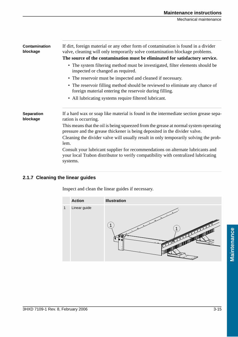
2.1.7 Cleaning the linear guides
Inspect and clean the linear guides if necessary.
Action Illustration
1 Linear guide
11

Maintenance instructions
Mechanical maintenance
3-16 3HXD 7109-1 Rev. 8, February 2006
Main
tenan
ce
2.1.8 Check ball element tightening torque
2.1.9 Gearbox
The gearbox is filled with oil on delivery. After every 5000 hours of operation the gearbox should be emptied and filled with new oil.
• The gearbox holds 7.8 litres
The oil must comply with the standards for high pressure oil under CLP 198-242 mm²/s/40°C.
1 Tighten the screws (24 pcs.) with 70 Nm.
Manufacturer Lubricant
MOBIL Mobilgear 630
Shell Omala Oil 220
Statoil Loadway EP 220

Maintenance instructionsElectrical maintenance
3HXD 7109-1 Rev. 8, February 2006 3-17
Mai
nte
nan
ce
2.2 Electrical maintenance
2.2.1 Inspection of electrical operations
The track motion should be checked monthly with regard to:
• All electrical operations
2.2.2 Check the emergency stop
The operation of the emergency stop should be checked monthly as follows:
2.2.3 Inspecting the cabling
Check monthly:
2.2.4 Check the connectors
Check monthly:
• that all connectors are made correctly and there is no risk for loose contact.
2.2.5 Inspection of the cable chain
Check monthly the visible part of the cable chain with regard to:
• The link system, replace if necessary.
• Points of attachment, replace if necessary.
Action
1 Let the carriage be still.
2 Press in the emergency stop.
3 Try to start the track motion.
If any cables ... then ...
have been damaged through wear or pinching replace the cable.
rub against sharp edges route the cable so that it runs freely.
Maintenance instructions
Electrical maintenance
3-18 3HXD 7109-1 Rev. 8, February 2006
Main
tenan
ce
2.2.6 Inspection of the junction boxes
Check, and rectify, if necessary, the junction boxes monthly with regard to:
• Damage
• Connections
• Tightness
2.2.7 Inspection of the drive motor
Check the drive motor monthly with regard to:
• Abnormal bearing noise
• Connections
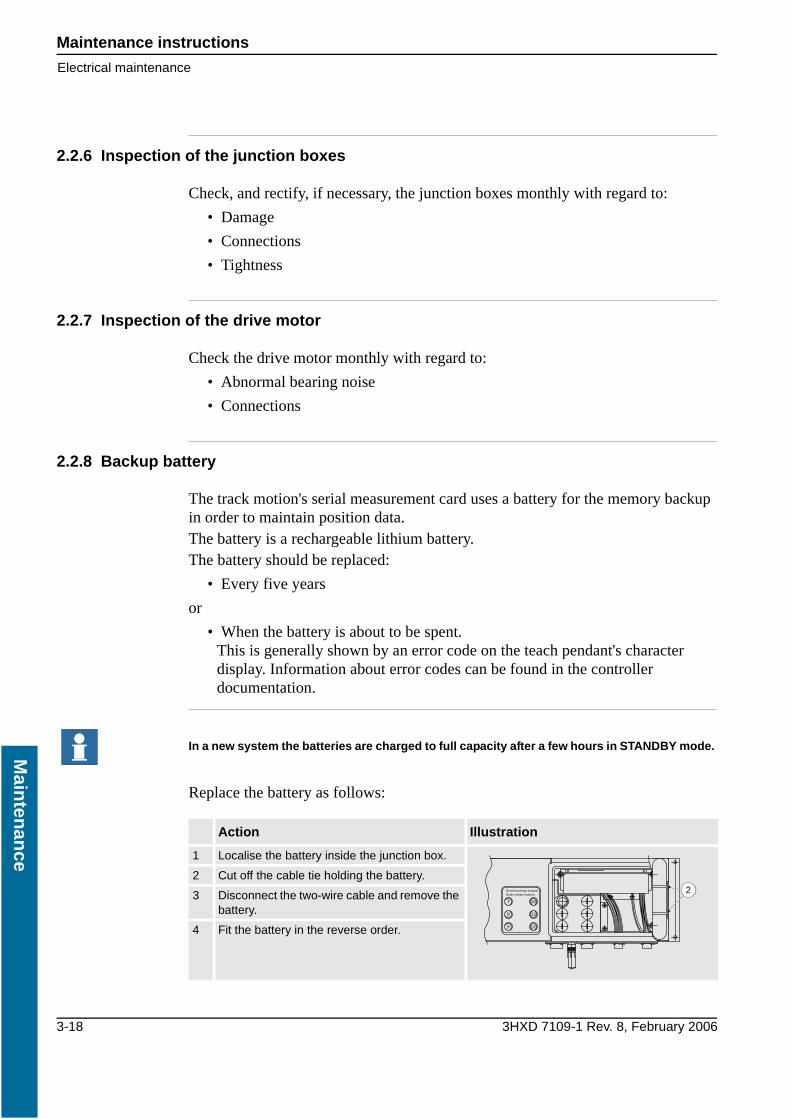
2.2.8 Backup battery
The track motion's serial measurement card uses a battery for the memory backup in order to maintain position data.The battery is a rechargeable lithium battery.The battery should be replaced:
• Every five years
or
• When the battery is about to be spent.This is generally shown by an error code on the teach pendant's character display. Information about error codes can be found in the controller documentation.
Replace the battery as follows:
In a new system the batteries are charged to full capacity after a few hours in STANDBY mode.
Action Illustration
1 Localise the battery inside the junction box.
2 Cut off the cable tie holding the battery.
3 Disconnect the two-wire cable and remove the battery.
4 Fit the battery in the reverse order.
Brake release buttonsBromslossnings knappar
7
8
9
10
11
12
2

Spare partsSpare parts independent of length
3HXD 7109-1 Rev. 8, February 2006 3-19
Mai
nte
nan
ce
3 Spare parts
3.1 Spare parts independent of length
3.1.1 Drive unit IRBT 4003F/6003F/7003F
Drive unit IRBT 6003S/4003S
Quantity Description Art. no. Item
1 Drive unit, IRB 4400 3HEA 801 301-001 -
1 Drive unit, IRB 6400R 3HEA 801 371-001 -
1 Drive unit, IRB 6600 3HEA 801 299-001 -
1 Drive unit, IRB 7600 3HEA 801 300-001 -
1 Motor IRB 4400, 6400R Low voltage(Yaskawa)
0506 262 880 1
1 Motor IRB 6600, IRB 7600 High voltage 3HXD 0100-380 1
1 Motor flange for motor 3HAC 10961-6 3HXD 1000-459 2
1 Gear drive, IRB 4400 0506 324 881 3
1 Gear drive IRB 6400R, 6600 0506 324 880 3
1 Gear drive IRB 7600 0506 323 880 3
1 Motor mounting 3HEA 801 171-002 4
2 Socket head cap screw 3HXG 1138-3 5
1 Spacer 3HXD 1000-492 6
1 Gear wheel 3HXD 1000-490 7
1 Retainer sleeve 3HXG 1000-506 8
1 Gearwheel cover (not in figure) 3HXD 0100-348 -
1
3
4
56
2
7
8

Spare parts
Spare parts independent of length
3-20 3HXD 7109-1 Rev. 8, February 2006
Main
tenan
ce
3.1.2 Carriage IRBT 4003F/6003F/7003F
Carriage IRBF 4003/6003/7003
Quantity Description Art. no. Item
Adaptors for robots
Adaptor for IRB 4400 3HXD 1658-1 1
4 Adaptor for IRB 6600, IRB 7600 3HXD 1000-273 2
16 Guide sleeve 3HXD 1000-274 3
16 Washer 2121 2017-733 4
4 Ball element 2185 0445-4 5
8 Scraper (linear guide) 3HXD 1000-205 6
2 Scraper 3HXD 1000-606 7
1
32 4
5
66
57

Spare partsSpare parts independent of length
3HXD 7109-1 Rev. 8, February 2006 3-21
Mai
nte
nan
ce
3.1.3 Central lubrication system (central unit)
.
Central lubrication system central unit
Quantity Description Art. no. Item
1 Grease tank Trabon 3HXD 1000-587 001
2 Bolt MC6S M10x30 0192238495 002
2 Washer BRB ST.22/10.5x20.0 0215100023 003
2 Nut &K steel 8.8 M10 0212601110 004
2 Angle bracket lubrication system 3HXD 1000-270 005
1 Cover for angle bracket 3HXD 1000-271 006
4 Bolt MC6S M6x16 0192238368 007
4 Washer BRB ST. 12/6.4x10.5 0215100013 008
1 AL-5 pump Trabon 3HXD 1000-628 009
1 Solenoid valve-Bürkert 3HXD 1000-585 010
1 Timer-Bürkert 3HXD 1000-586 011
2 Straight coupling type GE-8-LR 3HXD 1000-590 012
1 Distribution unit 25291928-3 014
2 Bolt MC6S M5x40 0192238339 015
2 Washer BRB ST. 10/5.3x100.0 02115100011 016
1 Blanking plug 25291920-4 017
2 Hose nipple 3/8x13 25292084-33 018
2 Hose clip 15-24 0252900405 019
1 Reducing nipple 25291921-3 020
2 Reducing nipple o1/4 - i1/8 25291921-2 021
4 Banjo bolt 25291926-2 022
4 Single banjo piece 25291008-2 023
1 Plastic hose PUN-6x1-SW 3HXG 1106-4 024
1 Plastic hose PUN-6x1-SW 3HXG 1106-4 025
1 Central lubrication cable (6400R, 4400) 3HXD 1318-20
1 Central lubrication cable (6600, 7600) 3HXD 1628-yy
1 Central lubrication hose 3HXD 1666-yy

Spare parts
Spare parts independent of length
3-22 3HXD 7109-1 Rev. 8, February 2006
Main
tenan
ce
3.1.4 Central lubrication system (carriage)
.
Central lubrication system carriage
Quantity Description Art. no. Item
1 Distribution cover Trabon 3HXD 1000-589 001
4 Bolt MC6s M6×40 0192238378 002
1 Washer BRB ST. 12/6.4×10.5 0215100013 003
6 Straight threaded coupling 3HXG 1000-591 004
1 Bracket for the oil brush 3HXD 1000-523 005
2 Bolt MC6S M8×16 0192238449 006
2 Washer BRB ST. 16/8.4×100.5 0215100018 007
1 Oil brush 3HXG 1000-562 008
2 Straight coupling 3HXG 1000-615 009
1 Brush 3HXG 1000-516 010
4 Reducing nipple (long) 3HXD 1000-611 011
4 Thread elbow coupling 3HXG 1000-561 012
1 Polyamide hose 8×1 L=600 3HXD 1583-1 013
1 Hydraulic pipe 8×1 3HXD 1656-1 014
1 Hydraulic pipe 8×1 3HXD 1656-2 015
1 Hydraulic pipe 8×1 3HXD 1656-3 016
1 Hydraulic pipe 8×1 3HXD 1656-4 017
1 Hydraulic pipe 8×1 3HXD 1656-5 018
10 Single pipe clamp 3HXG 1145-1 019
5 Double pipe clamp 3HXG 1145-2 020
A
C
B

Spare partsSpare parts dependent on length
3HXD 7109-1 Rev. 8, February 2006 3-23
Mai
nte
nan
ce
3.2 Spare parts dependent on length
3.2.1 Cable chain
Complete cable chain including standard cable harness.
The “x” in the article number in the table should be replaced by the track motion’s travel length rounded up to the nearest metre. Accordingly, a complete cable chain for IRB 4400 with the travel length of 2.7 metres has the article number 3HXD 1552-23, with a travel length of 3.7 metres the article number will be 3HXD 1552-24, etc.
3.2.2 Cable tray
Spare parts for the cable tray on IRBT 4003F/6003F/7003F:
Cable tray IRBT 4003F/6003F/7003F
Optional cables are not supplied with the cable chain. These are ordered separately according to .
Quantity Description Art. no.
1 Complete cable chain for IRB 6600/IRB 7600 3HXD 1552-1x
1 Complete cable chain for IRB 4400 3HXD 1552-2x
1 Complete cable chain for IRB 6400R 3HXD 1552-3x
Quantity with different travel lengths
Description 1.7 2.7 3.7 4.7 5.7 6.7 7.7 Art. no. Item
Levelling plates 3 4 6 7 9 10 12 3HXD 1000-414 1
Lower bracket for the cable chain
3 4 4 5 5 6 6 3HXD 1000-410 2
Guide plate for the cable chain
1 1 1 1 1 1 1 3HXD 1000-642 3
Guide plate for the cable chain
- 1 1 2 2 3 3 3HXD 1000-583 4
3
3
1
1
1
1
1
2
2
2
2
2

Spare parts
Spare parts dependent on length
3-24 3HXD 7109-1 Rev. 8, February 2006
Main
tenan
ce
3.2.3 Stand
Spare parts for the stand on IRBT 4003F/6003F/7003F.
Stand IRBT 6003S/4003S
Quantity with different travel lengths
Description 1.7 2.7 3.7 4.7 5.7 6.7 7.7 Art. no. Item
Linear guide 45 L=1000 - 2 - - 2 - - 3HXG 1160-1 1
Linear guide 45 L=2000 - - 2 6 6 2 4 3HXG 1160-2 1
Linear guide 45 L=3000 2 2 2 - - 4 2 3HXG 1160-3 1
Gear rack L=1000 - 1 - 1 - 1 2 3HXD 1557-1 2
Gear rack L=2000 1 1 2 2 3 3 3 3HXD 1557-2 2
Cover plate, rack 2 3 4 5 6 7 8 3HXD 1000-599 3
Cover plate end (Left) 1 1 1 1 1 1 1 3HXD 1000-597 4
Cover plate end (Right) 1 1 1 1 1 1 1 3HXD 1000-598 5
Mechanical stop 2 2 2 2 2 2 2 3HXD 1000-596 6
Flexible stop 4 4 4 4 4 4 4 2196 065-49 7
Side plate L=2000 - 2 1 - 2 1 - 3HXD 1655-2 -
Side plate L=3000 1 - 1 2 1 2 3 3HXD 1655-3 -
4
1
326
1
5
7
6 7
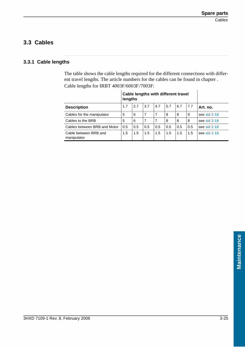
Spare partsCables
3HXD 7109-1 Rev. 8, February 2006 3-25
Mai
nte
nan
ce
3.3 Cables
3.3.1 Cable lengths
The table shows the cable lengths required for the different connections with differ-ent travel lengths. The article numbers for the cables can be found in chapter .Cable lengths for IRBT 4003F/6003F/7003F:
Cable lengths with different travel lengths
Description 1.7 2.7 3.7 4.7 5.7 6.7 7.7 Art. no.
Cables for the manipulator 5 6 7 7 8 8 9 see sid 2-18
Cables to the BRB 5 6 7 7 8 8 8 see sid 2-18
Cables between BRB and Motor 0.5 0.5 0.5 0.5 0.5 0.5 0.5 see sid 2-18
Cable between BRB and manipulator
1.5 1.5 1.5 1.5 1.5 1.5 1.5 see sid 2-18

Spare parts
Cables
3-26 3HXD 7109-1 Rev. 8, February 2006
Main
tenan
ce

Sp
ecif
ikat
ion
3HXD 7109-1 Rev. 8, February 2006 index-i
Index
AAcceleration ............ 1-9, 1-10Automatic lubrication system
Activate .......................2-25
CCable central lubrication ..2-20, 2-21, ..............................2-22Cable chain ....................... 1-2Cable tray ............... 1-2, 2-14Calibration ........................ 1-7Carriage table .. 1-3, 1-15, 2-5Carriage .........see Carriage table
Compact .........................1-15Controller ............... 1-3, 1-14
Connection cable ..........1-15Terminal post J1 ...........2-17
Customer Cable ..... 1-16, 2-21Customer cable ................2-22
DDegree of protection 1-9, 1-10
EEnd plates .......................2-13Extra load ......................... 2-5
FFoundation ........................ 2-5
GGear play ........................2-30Gear rack .......................... 1-2Gear racks .......................2-12Gearbox .................. 1-2, 3-16
HHeight ............................1-12
IInLine .............................2-14IRB 7600 .....................see Robot
IRBT 7003S ....................1-15Compact ......................1-15Principal layout .............. 1-2
KKey to symbols .................. 1-5
LLength ............................1-11Levelling bolts .......2-10, 2-13Levelling plates .................2-9Lift ...................................1-5Linear guide ............1-2, 2-10
MManipulator .......................1-3
Assemble .............1-6, 2-14Cable length .................3-25Dynamic loads ...............2-5Static load ......................2-5Terminal post J1 ...........2-17
Maximum load ........1-9, 1-10Motor ...............................1-2Motor cable .....................2-21
PPosition Switch Cable .... 2-20, 2-21, ..............................2-22Power Cable ....................2-22Power cable .....................2-19Power cable floor .............1-15
RRail module .... see Stand module
Repeater accuracy ....1-9, 1-10Resolver cable ......2-19, 2-21, 2-22Retardation ..............1-9, 1-10Robot ................................1-3
Connection cable ..........1-15Technical requirements .1-14also see Manipulator
Robot system ...........1-3, 2-29
SS4Cplus ............... see Controller
Safety ...............................1-5Serial Measurement Box .....1-2Serial measurement cable 2-19, 2-21, ..............................2-22SMBsee Serial Measurement Box ...............................................1-2
Stand ................................1-3Assembly .......................2-8Dimension table ...1-11, 2-6Length .................1-9, 1-10Spare parts ...................3-24Weight ................1-9, 1-10
Stand module .................... 1-3
TTerminal post J1 .............. 2-17The lifting zone ................. 2-1Track Motion .....1-3, 1-5, 1-7
Dimensions ..........1-9, 1-10Calibration .................. 2-29Connection point J1 ..... 2-17Lifting .......................... 2-1Performance .................. 1-9Principal layout ............. 1-2Variants ...................... 1-15
Track ...............see Track Motion
Travel length ..1-3, 1-9, 1-10, 1-11, .1-15, 2-6, 2-14, 2-24, 3-23, ....................3-24, 3-25Travel speed ............1-9, 1-10
WWeight ....................1-9, 1-10Width ............................. 1-12Working area .................. 2-29

index-ii 3HXD 7109-1 Rev. 8, February 2006
Sp
ecifikation


3HXD 7109-1 Rev. 8, February 2006