track relaying train for broad gauge (1676 mm) … · 2.6 it shall be capable of negotiating curves...
TRANSCRIPT

Page 1 of 23
TRACK RELAYING TRAIN FOR BROAD GAUGE (1676 MM) TECHNICAL SPECIFICATIONS
1.0 GENERAL
1.1 On heavy traffic density, high speed routes, track renewal by semi-mechanized or manual means involving slow progress, longer lengths and duration of speed restrictions, low speeds after renewals is no more feasible. Indian Railways plan to procure a track renewal system for full mechanization of track renewal on heavy density routes capable of achieving high progress in a given traffic block, track laying with close track geometry tolerances and restoration of traffic at higher speeds after the clearance of traffic block. These performance specifications have been drafted for a fully mechanized track relaying system to meet these requirements, hereinafter called the “machine”.
1.2 The technical specifications have been drafted to reflect the performance and quality
requirements of the equipment in a neutral manner without bias to any specific manufacturer. Bidders are requested to carefully study the specification and assure that their equipment fully comply with these specifications. Thereafter, if a bidder feels that his equipment can substantially meet the performance and quality requirement of the equipment but does not fully satisfy a particular specification, he should immediately seek clarification from the purchaser prior to submission of bids as to whether such deviation is substantive or not.
1.3 System/sub systems of the working mechanisms of the machine as per para ‘3’ in particular and all the items of the specifications in general shall be described in detail with sketches to show the manner in which the requirement of the specifications are accomplished by the machine offered.
1.4 Photographs/sketches of the type of machine offered in work mode shall be enclosed with
the offer. This shall also show close-ups of various working assemblies/systems and the full machine. The tenderer shall furnish a video cassette or VCD showing the working of machine in real time under field conditions.
1.5 Since the machine under procurement comprises of a main machine and several auxiliary smaller machines, the supplier must ensure that they are matching in capacity with respect to the targeted output mentioned in para. 3.4(a) and 3.11.
1.6 To assess the Indian Railways need for more or less auxiliary machine as compared to offered configuration, the suppliers, in their financial bid shall quote the unit rate for main machine and auxiliary machines separately.
2.0 DIMENTIONAL AND OPERATING REQUIREMENTS
2.1 The diesel powered, self propelled track relaying machine shall be robust, of the latest design, reliable and suitable for working on Indian Railways track. Straight, transitions and curves on broad gauge (1676mm). The design and dimensions of the machine and components shall be to metric standards. Quality assurance during manufacture of the machine shall be as per ISO-9001.
Page 2 of 23
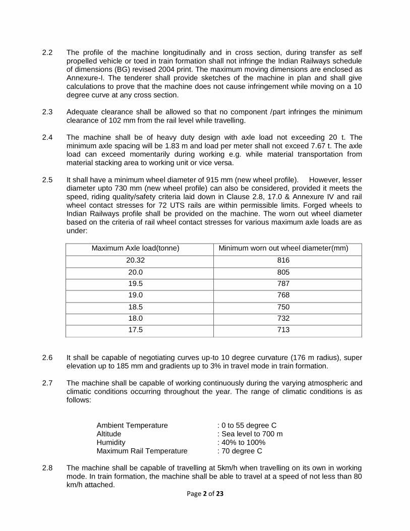
2.2 The profile of the machine longitudinally and in cross section, during transfer as self propelled vehicle or toed in train formation shall not infringe the Indian Railways schedule of dimensions (BG) revised 2004 print. The maximum moving dimensions are enclosed as Annexure-I. The tenderer shall provide sketches of the machine in plan and shall give calculations to prove that the machine does not cause infringement while moving on a 10 degree curve at any cross section.
2.3 Adequate clearance shall be allowed so that no component /part infringes the minimum
clearance of 102 mm from the rail level while travelling.
2.4 The machine shall be of heavy duty design with axle load not exceeding 20 t. The minimum axle spacing will be 1.83 m and load per meter shall not exceed 7.67 t. The axle load can exceed momentarily during working e.g. while material transportation from material stacking area to working unit or vice versa.
2.5 It shall have a minimum wheel diameter of 915 mm (new wheel profile). However, lesser
diameter upto 730 mm (new wheel profile) can also be considered, provided it meets the speed, riding quality/safety criteria laid down in Clause 2.8, 17.0 & Annexure IV and rail wheel contact stresses for 72 UTS rails are within permissible limits. Forged wheels to Indian Railways profile shall be provided on the machine. The worn out wheel diameter based on the criteria of rail wheel contact stresses for various maximum axle loads are as under:
2.6 It shall be capable of negotiating curves up-to 10 degree curvature (176 m radius), super
elevation up to 185 mm and gradients up to 3% in travel mode in train formation.
2.7 The machine shall be capable of working continuously during the varying atmospheric and climatic conditions occurring throughout the year. The range of climatic conditions is as follows:
Ambient Temperature : 0 to 55 degree C Altitude : Sea level to 700 m Humidity : 40% to 100% Maximum Rail Temperature : 70 degree C 2.8 The machine shall be capable of travelling at 5km/h when travelling on its own in working
mode. In train formation, the machine shall be able to travel at a speed of not less than 80 km/h attached.
Maximum Axle load(tonne) Minimum worn out wheel diameter(mm)
20.32 816
20.0 805
19.5 787
19.0 768
18.5 750
18.0 732
17.5 713

Page 3 of 23
2.9 It shall be capable of working without requiring power block in electrified section. 25 KVA
current is used for traction through an overhead wire at 5.5 m above rail level. On bridges and tunnels, the height is restricted to 4.8m.
2.10 While working on double line section, it shall not infringe the adjoining track and it shall be possible to permit trains at full speed on that track. Minimum spacing of track is 4.265 m.
3.0 WORKING MECHANISM.
3.1 The machine is meant to renew the track, which it is in possession, under traffic block. The new rails proposed to be relayed shall be spread in advance on cess on either side of the track to be renewed. The new sleepers to be relayed shall be stacked in attached flat wagons (BFRs) to the work spot along with the machine.
The machine should involve minimal pre-block base depot activities. The machine should
be capable of picking and handling a group of loose sleepers without any prior formation of track panels as a preparatory activity in the base depot.
To maintain continuity of work even with long train formation, the machine shall be
equipped with minimum two sleeper handling gantries to lead the new concrete sleepers from attached BFRs to the sleeper handling area on the machine.
3.2 The machine shall be capable of working on all types of track structures including long welded rails of 60 kg/52kg/90-R sections on concrete/ST/CST-9/wooden sleepers on plain as well as curves up-to 250 m radius and 165 mm cant. It shall be capable of relaying on gradients upto 2% in uphill direction. On steeper gradients, it shall be able to work down the grade.
3.3 The old track may comprise of fish plated, short welded, or long welded rails on concrete, CST-9, steel trough or wooden sleepers. The fish plated joints in old track have 2 sleepers closely spaced. In respect of CST-9 sleeper track, there may be 3 to 5 sleepers with reverse jaws in every rail panel of about 13 m. It is not possible to lift the rail up from the sleepers directly unless the reverse jaw sleepers are removed or the reverse jaw is cut. The supplier shall offer a suitable mechanism to tackle these situations.
In the area where the old track has been dismantled and new track is being laid, the
working components of the machine are supported on a crawler based sled assembly or any similar assembly. The design of such assembly should be such as to climb over the old sleepers without pushing them forward on account of settlement of the sled assembly, even in a newly deep screened track where ballast consolidation has not yet taken place. This becomes more important in CST-9 and wooden sleepers where the old sleepers gets lifted up while old rail is leaving it & hence due to higher level of lifted sleeper, the assembly is not able to negotiate over the sleeper without putting up of guiding plates. The system of such mechanism should be so designed as to avoid any use of guiding plates by the staff handling the plates manually.
3.4 The old sleeper and rail separation mechanism shall be such that the sleepers do not lift
up while the rail is leaving it and suitable mechanism with control with one operator may be given at suitable location so that the rails can be moved in transverse direction either way to avoid lifting of sleepers in addition to design of assembly capable of negotiating lifted sleeper itself.
Page 4 of 23
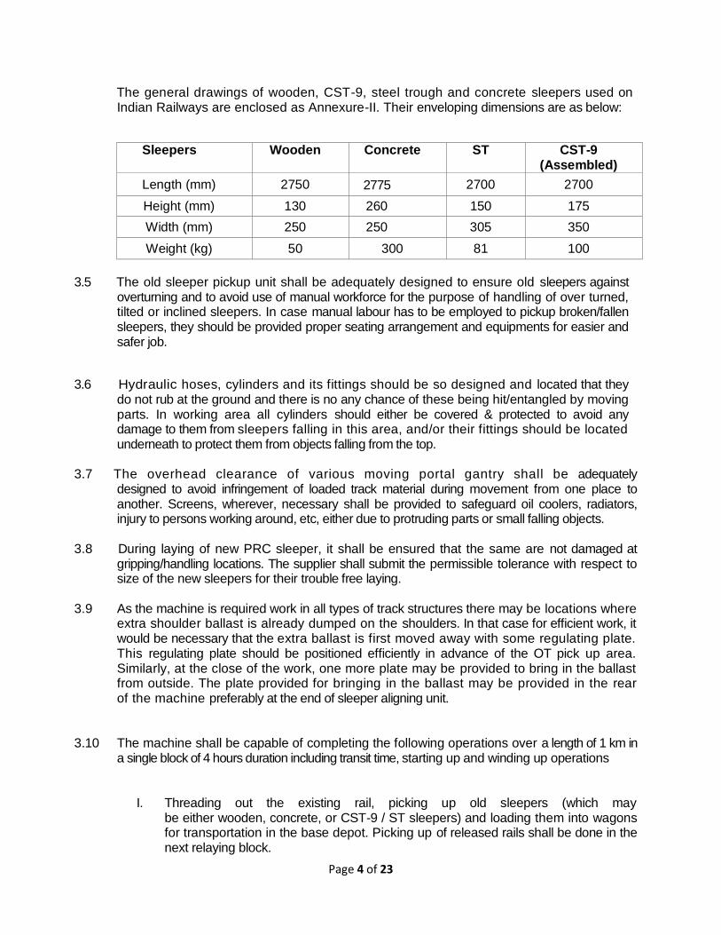
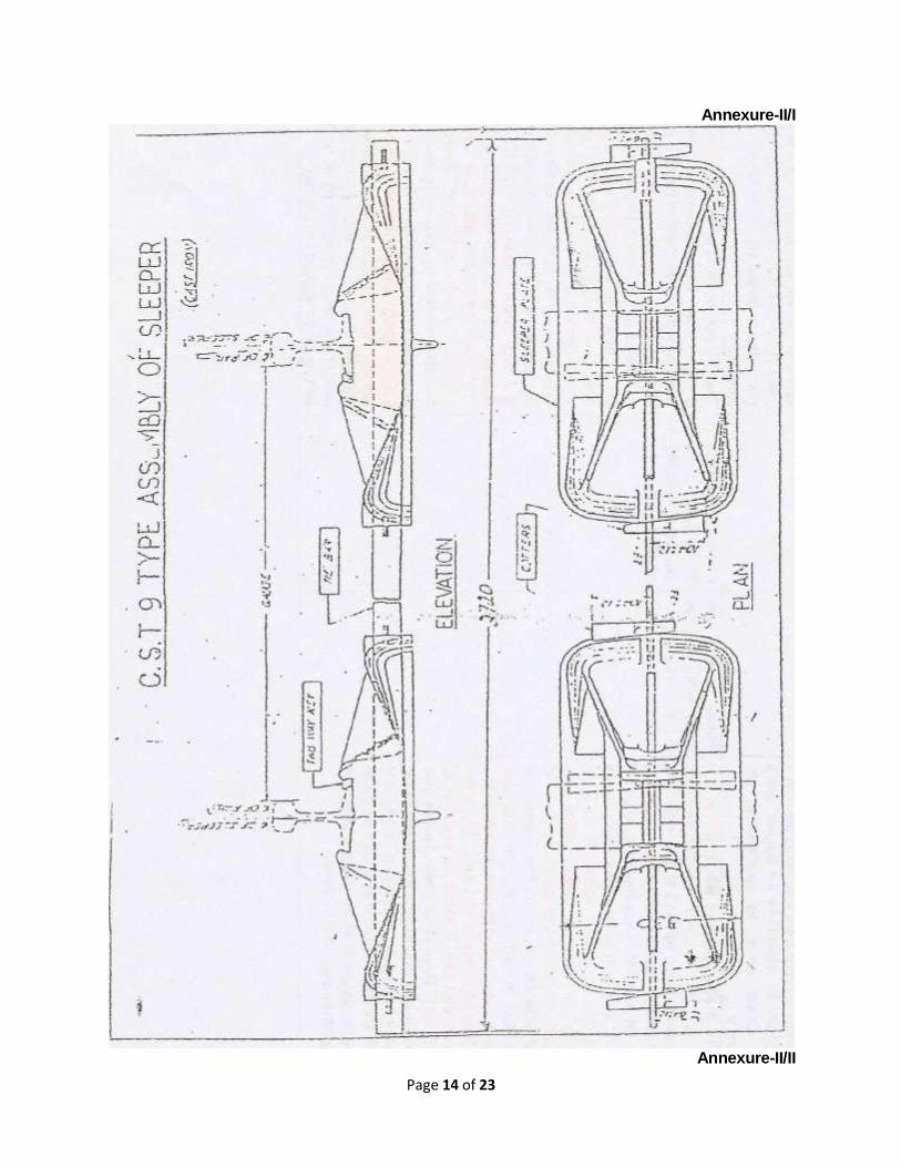
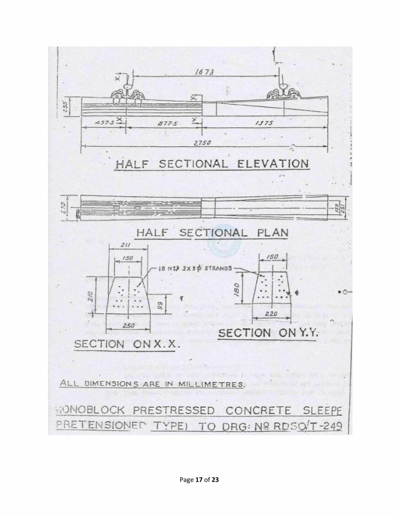
The general drawings of wooden, CST-9, steel trough and concrete sleepers used on Indian Railways are enclosed as Annexure-II. Their enveloping dimensions are as below:
Sleepers Wooden Concrete ST CST-9
(Assembled)
Length (mm) 2750 2775 ',
2700 2700
Height (mm) 130 260 150 175
Width (mm) 250 250 305 350
Weight (kg) 50 300 81 100
3.5 The old sleeper pickup unit shall be adequately designed to ensure old sleepers against
overturning and to avoid use of manual workforce for the purpose of handling of over turned, tilted or inclined sleepers. In case manual labour has to be employed to pickup broken/fallen sleepers, they should be provided proper seating arrangement and equipments for easier and safer job.
3.6 Hydraulic hoses, cylinders and its fittings should be so designed and located that they do not rub at the ground and there is no any chance of these being hit/entangled by moving parts. In working area all cylinders should either be covered & protected to avoid any damage to them from sleepers falling in this area, and/or their fittings should be located underneath to protect them from objects falling from the top.
3.7 The overhead clearance of various moving portal gantry shall be adequately
designed to avoid infringement of loaded track material during movement from one place to another. Screens, wherever, necessary shall be provided to safeguard oil coolers, radiators, injury to persons working around, etc, either due to protruding parts or small falling objects.
3.8 During laying of new PRC sleeper, it shall be ensured that the same are not damaged at gripping/handling locations. The supplier shall submit the permissible tolerance with respect to size of the new sleepers for their trouble free laying.
3.9 As the machine is required work in all types of track structures there may be locations where
extra shoulder ballast is already dumped on the shoulders. In that case for efficient work, it would be necessary that the extra ballast is first moved away with some regulating plate. This regulating plate should be positioned efficiently in advance of the OT pick up area. Similarly, at the close of the work, one more plate may be provided to bring in the ballast from outside. The plate provided for bringing in the ballast may be provided in the rear of the machine preferably at the end of sleeper aligning unit.
3.10 The machine shall be capable of completing the following operations over a length of 1 km in a single block of 4 hours duration including transit time, starting up and winding up operations
I. Threading out the existing rail, picking up old sleepers (which may be either wooden, concrete, or CST-9 / ST sleepers) and loading them into wagons for transportation in the base depot. Picking up of released rails shall be done in the next relaying block.

Page 5 of 23
II. Scarifying and levelling of ballast bed.
III. Laying of concrete sleepers in good alignment at the required spacing continuously one after the other, which may vary from 550 mm to 700mm.
IV. Laying of new rails continuously that were previously unloaded by the side of the track in position either welded or fish-plated.
V. Fastening new rails to sleepers.
The tenderer shall describe in detail the mechanism of above operations with respect to the equipment offered by him/them.
3.11 A mechanized system, for example dynamic plough, shall be provided for scarifying and
levelling the ballast automatically to pre-set level. It shall be capable of lowering the old track by under cutting the ballast up to 80 to 100 mm below the level of existing old track, in order to take care of overhead clearance requirement depending upon site condition on account of increased height differential of sleepers.
3.12 Ahead of dynamic plough or such similar system, a suitable mechanism should be provided to dig a reception trench on either side of the track for accommodating the ballast dislodged by the Dynamic Plough.
3.13 Picking up of released rails "in the next relaying block and loading on to railways flat wagons
(BFRs). The equipment for this shall be a part of the complete offer as an auxiliary self propelled machine".
3.14 While laying new long welded rails on the track, it shall be ensured that permissible bending
stresses of 52 kg or 60 kg rails are not exceeded during threading in operation.
3.15 The sleeper laying and spacing mechanism shall be provided with accumulators etc. so that the "Setting of spacing" do not get disturbed even if the machine stops due to any reason in between the work and there is a drop in hydraulic pressure.
3.16 Handling and conveyance of sleepers and rails shall be such as not to cause damage to
rails and sleepers. It should be ensured that hydraulic circuits are designed in such a way that the hydraulic cylinders work smoothly without any jerks. This is more important in the area where new sleepers are being handled.
3.17 The clearance & aligning mechanism of new PSC sleeper conveyor assemblies shall
be smooth in such a way that the sleeper do not get entangled or hit by anything and there shall be no need to manually handle such sleepers.
3.18 The flat wagons required for the TRT shall be supplied by the Purchaser free of cost in
good working condition, suitable for any required modification. The modifications shall be carried out by the tenderer at his own cost in India to make them suitable for this method of
Page 6 of 23
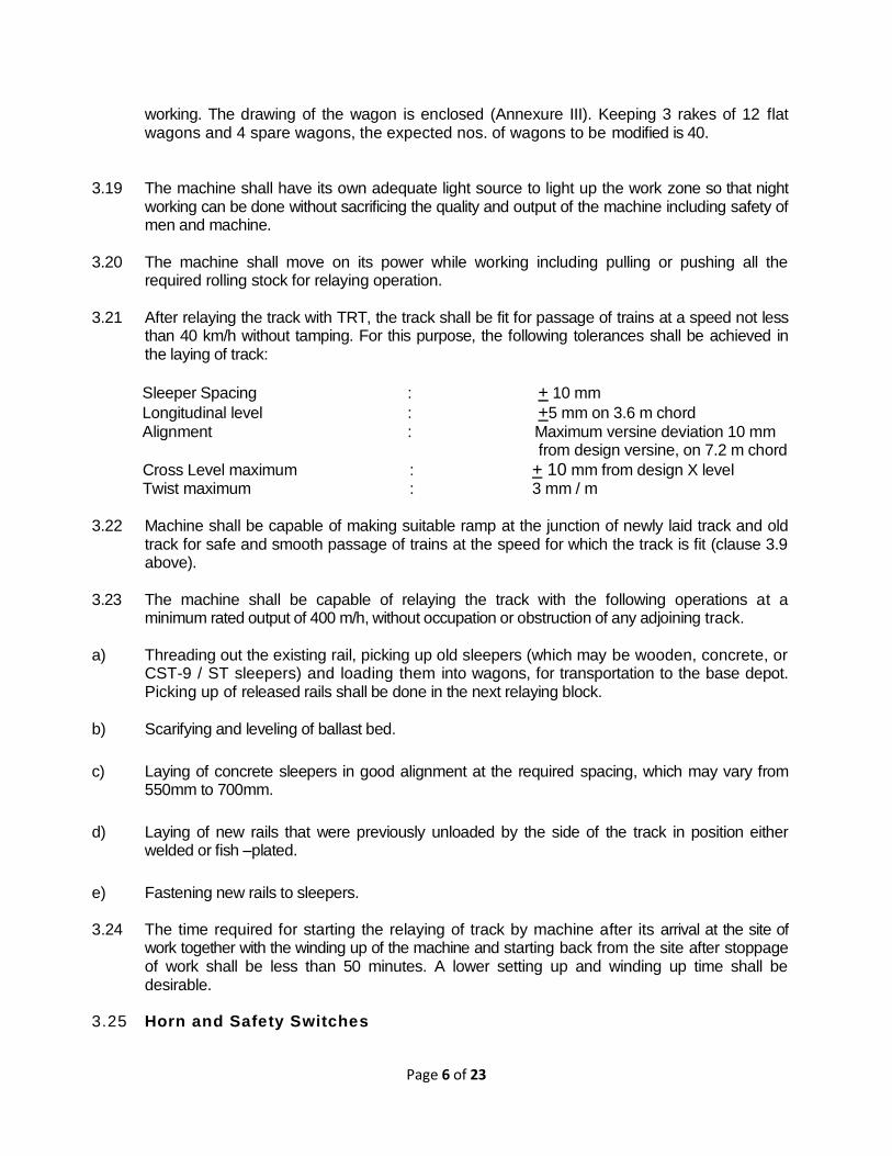
working. The drawing of the wagon is enclosed (Annexure III). Keeping 3 rakes of 12 flat wagons and 4 spare wagons, the expected nos. of wagons to be modified is 40.
3.19 The machine shall have its own adequate light source to light up the work zone so that night working can be done without sacrificing the quality and output of the machine including safety of men and machine.
3.20 The machine shall move on its power while working including pulling or pushing all the required rolling stock for relaying operation.
3.21 After relaying the track with TRT, the track shall be fit for passage of trains at a speed not less
than 40 km/h without tamping. For this purpose, the following tolerances shall be achieved in the laying of track:
Sleeper Spacing : + 10 mm
Longitudinal level : +5 mm on 3.6 m chord
Alignment : Maximum versine deviation 10 mm from design versine, on 7.2 m chord
Cross Level maximum : + 10 mm from design X level Twist maximum : 3 mm / m 3.22 Machine shall be capable of making suitable ramp at the junction of newly laid track and old
track for safe and smooth passage of trains at the speed for which the track is fit (clause 3.9 above).
3.23 The machine shall be capable of relaying the track with the following operations at a
minimum rated output of 400 m/h, without occupation or obstruction of any adjoining track.
a) Threading out the existing rail, picking up old sleepers (which may be wooden, concrete, or CST-9 / ST sleepers) and loading them into wagons, for transportation to the base depot. Picking up of released rails shall be done in the next relaying block.
b) Scarifying and leveling of ballast bed.
c) Laying of concrete sleepers in good alignment at the required spacing, which may vary from 550mm to 700mm.
d) Laying of new rails that were previously unloaded by the side of the track in position either welded or fish –plated.
e) Fastening new rails to sleepers. 3.24 The time required for starting the relaying of track by machine after its arrival at the site of
work together with the winding up of the machine and starting back from the site after stoppage of work shall be less than 50 minutes. A lower setting up and winding up time shall be desirable.
3.25 Horn and Safety Switches
Page 7 of 23
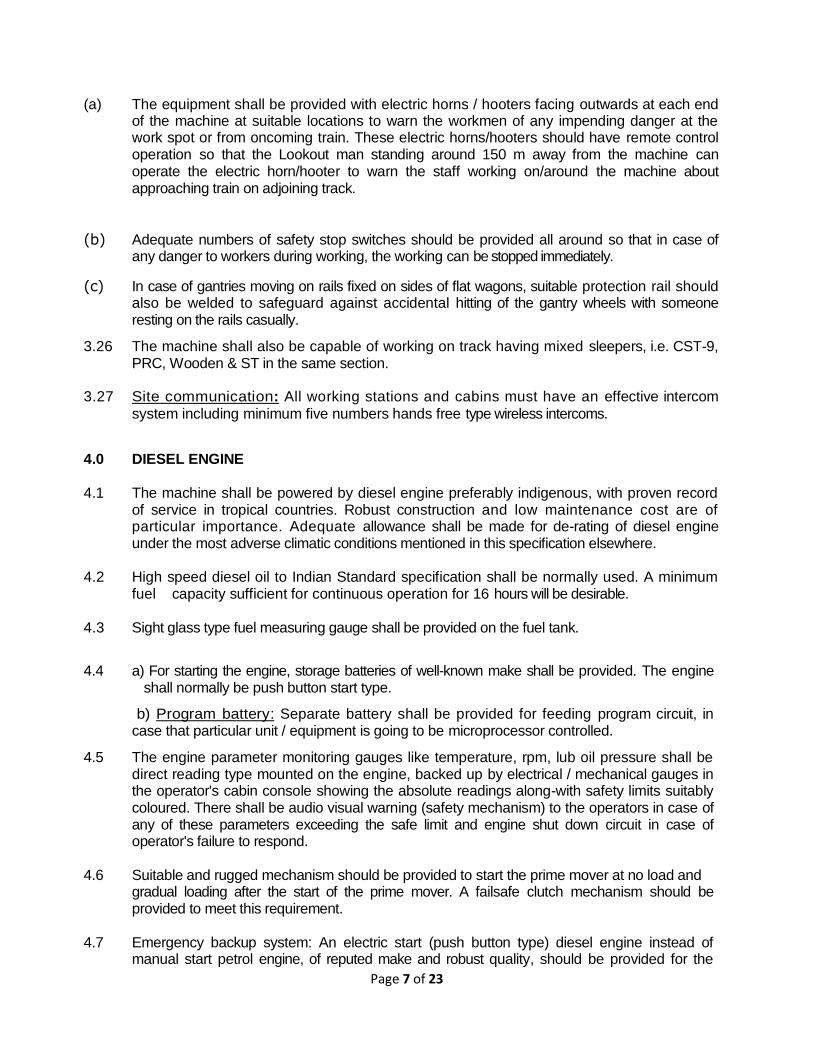
(a) The equipment shall be provided with electric horns / hooters facing outwards at each end of the machine at suitable locations to warn the workmen of any impending danger at the work spot or from oncoming train. These electric horns/hooters should have remote control operation so that the Lookout man standing around 150 m away from the machine can operate the electric horn/hooter to warn the staff working on/around the machine about approaching train on adjoining track.
(b) Adequate numbers of safety stop switches should be provided all around so that in case of any danger to workers during working, the working can be stopped immediately.
(c) In case of gantries moving on rails fixed on sides of flat wagons, suitable protection rail should also be welded to safeguard against accidental hitting of the gantry wheels with someone resting on the rails casually.
3.26 The machine shall also be capable of working on track having mixed sleepers, i.e. CST-9, PRC, Wooden & ST in the same section.
3.27 Site communication: All working stations and cabins must have an effective intercom
system including minimum five numbers hands free type wireless intercoms.
4.0 DIESEL ENGINE
4.1 The machine shall be powered by diesel engine preferably indigenous, with proven record of service in tropical countries. Robust construction and low maintenance cost are of particular importance. Adequate allowance shall be made for de-rating of diesel engine under the most adverse climatic conditions mentioned in this specification elsewhere.
4.2 High speed diesel oil to Indian Standard specification shall be normally used. A minimum fuel capacity sufficient for continuous operation for 16 hours will be desirable.
4.3 Sight glass type fuel measuring gauge shall be provided on the fuel tank.
4.4 a) For starting the engine, storage batteries of well-known make shall be provided. The engine shall normally be push button start type.
b) Program battery: Separate battery shall be provided for feeding program circuit, in case that particular unit / equipment is going to be microprocessor controlled.
4.5 The engine parameter monitoring gauges like temperature, rpm, lub oil pressure shall be direct reading type mounted on the engine, backed up by electrical / mechanical gauges in the operator's cabin console showing the absolute readings along-with safety limits suitably coloured. There shall be audio visual warning (safety mechanism) to the operators in case of any of these parameters exceeding the safe limit and engine shut down circuit in case of operator's failure to respond.
4.6 Suitable and rugged mechanism should be provided to start the prime mover at no load and gradual loading after the start of the prime mover. A failsafe clutch mechanism should be provided to meet this requirement.
4.7 Emergency backup system: An electric start (push button type) diesel engine instead of manual start petrol engine, of reputed make and robust quality, should be provided for the

Page 8 of 23
purpose of activating various units, which stop working due to breakdown of TRT engine. This is of utmost importance to ensure that traffic block is not bursted on account of failure of TRT engine. The starter battery and charging alternator should be of good quality.
5.0 COOLING SYSTEM.
The cooling system for prime mover as well as system oil shall be efficient and designed for a maximum ambient temperature of 550C. Supplier may note that the machine shall be working under extreme dusty conditions and the cooling mechanism should be maintainable under these conditions.
6.0 DRIVING MECHANISM.
The machine should be provided with an efficient traction drive system for traction during the operation.
6.1 The power transmission to various driving axles may be hydrostatic or electric. However, the system should be so designed that all the driving wheels work in synchronization and there is no slippages / skidding of the wheels during the work drive. It shall haul a minimum 20 PSC loaded flats plus 3 empty wagons and one material wagon (revised). To achieve this a minimum of 8 driving axles (4 driving bogies) shall be provided on the main machine".
6.2 Suitable differential systems may be provided between coupled wheels on the same bogie.
6.3 Suitable flow divider / throttling arrangement may be provided to equalize the tractive efforts amongst different bogies. Adequate gauges shall be provided to indicate the power sharing among different driving bogies to prevent overstressing of any traction bogie or its components.
6.4 The supplier shall provide the necessary technical details including circuit diagrams to confirm
the above requirements.
6.5 Adequate gauges (flow meter) and solenoid valves shall be provided near linkage assembly, for indication, flow control and carrying out necessary adjustment in the field. It will be preferable to have a proportional valve arrangement in place of linkage assembly wherever synchronous movements are essential.
6.6 To the extent possible hydraulic and pneumatic component/assembly should be fixed at
suitable location preferably on the side frame of the machine so as to avoid the need of going on top of the machine/ gantry frame for day-today maintenance schedules.
7.0 BRAKES
The machine shall be fitted with the airbrakes. The brakes shall be protected from ingress of water, grease, oil or other substances, which may have an adverse effect on them. The brake lining shall be suitable for high ambient temperature of 55 degree Centigrade. The force required for operating the brake shall not exceed 10 kg at the handle while applying by hand and 20 kg on the pedal, when applied by foot. In addition, mechanical brakes shall also be provided for use in an eventuality of failure as well as for parking. An additional through pipe with attachment shall be provided in the machine for attaching the machine in train formation having vacuum compressed air breaking system.

Page 9 of 23
8.0 HOOKS AND BUFFERS.
The machine shall be fitted with transition CBC couplings and buffers of Indian Railways' design on both ends for coupling it with other vehicles for running in train formation.
9.0 ELECTRIC EQUIPMENT AND LIGHTING
The electric equipment to be provided shall conform to relevant standard specifications and shall be suitable for Indian climatic conditions. The machine shall be equipped with headlights at each end and with two front and rear parking lights, which can be switched to red or white according to the direction of the travel. Powerful swivelling floodlights shall also be provided to illuminate the working area sufficiently bright for efficient working during night.
10.0 CHASSIS AND UNDERFRAME
The chassis shall be of standard welded steel sections and of steel sheets so as to permit transportation of the machine in train formation without endangering safety to the train. The under-frame shall be sufficiently robust for safe travel of the machine in train formation and not necessarily as the last vehicle.
11.0 CABINS
The machine shall be equipped with fully enclosed cabins with good visibility of the working area.
11.1 The gauges, instruments and controls shall be suitably located in the operator's cab/console so that they can be observed without undue fatigue to the operator. One screen wiper preferably operated by compressed air shall be provided on the windscreens.
11.2 Fire extinguisher (dry chemical type) shall be provided in the cab.
11.3 The machine shall be provided with adequate space for keeping the tools and spares
required for on-site repair of the machine to attend the breakdown and other working requirements.
11.4 A closed circuit TV system should be provided to enable the gantry driver to see any
obstruction/infringement when travelling in the direction where visibility is not covered by any cabin.
12.0 TOOLS AND INSTRUCTION MANUALS
12.1 Each machine shall be supplied with a complete kit of tools required by operator in
emergency and for normal working of the machine. The list of tools to be provided shall also include all tools necessary for maintenance and repair of the entire machine including specialized equipment. All special tools shall be listed and catalogued illustrating the method of application.
12.2 One portable welding plant of reputed make with adequate capacity along with sufficient cables or lead shall be provided with the machine for day to day repairing of machine and its wearing parts. The portable welding set so provided should be housed in protected and covered & secured manner preferably near the moving parts of the machine.

Page 10 of 23
12.3 Detailed operating manual, maintenance and service manuals shall be specifically prepared
and three copies of these shall be supplied with each machine.
12.4 Alongwith the manuals as mentioned in 12.1 above, the manufacturer shall also supply circuit diagrams of electrical, hydraulic, pneumatic and electronic circuits used on the machine. Trouble shooting diagram/table shall also be supplied. In addition, the supplier shall provide dimension drawings with material description of items like rubber seals, washers, springs, bushes, metallic pins etc. Main features of items like hydraulic pumps motors and such other bought out components/ assemblies shall be furnished by the tenderer.
12.5 The tenderer shall submit the list of tools, manuals, circuit diagrams and other technical literature/drawings to be supplied alongwith each machine as above, for operation, servicing, maintenance and trouble shooting, alongwith his offer. The list can be modified to suit the purchaser's requirement, while examining the offer.
12.6 The firm shall provide detailed technical drawings and specifications of wheels and axles used in the machine with detailed code of procedure for ultrasonic testing of wheels and axles of all types. The above details shall be provided in 4 sets.
12.7 While offering the machine for first inspection, the supplier shall submit three copies of
complete literature including operation, service and maintenance manuals, complete electrical, hydraulic and pneumatic circuit diagram, trouble shooting charts, component drawings/descriptions and other relevant technical details so as to maintain master copies of these documents in Indian Railways Institutions and a reference documents for inspecting officer. All manuals/ diagrams shall be provided in hard as well as soft versions both. With delivery of each machine one set of manuals to be delivered to TM directorate, RDSO, Lucknow and one to IRTMTC Allahabad.
13.0 SPARE PARTS
The expected life of the components, used in the machine, shall be advised along with their condemning limits. The machine shall be supplied with necessary spare parts for the operation and maintenance of the machine for a period of two years i.e. working for about 1200 hrs. The spare parts required shall be detailed in a separate list indicating description, part number and whether imported or indigenous.
The manufacturer shall be responsible for the subsequent availability of spare parts to ensure trouble free service for the life of the machine (15 years).
For indigenous parts and bought out components and assemblies, the source (original equipment manufacturer's reference and part no.) and other relevant technical details shall be supplied while offering the first machine for inspection.
14.0 MAKER'S TEST CERTIFICATE.
Copies of the Maker's certificate guaranteeing the performance of the equipment shall be supplied in duplicate along with the delivery of the each machine.
15.0 OPERATORS.

Page 11 of 23
The number of operators and allied staff for working of the machine under normal condition shall be indicated, specifying their duties and minimum qualifications.
16.0 Tenderer is expected to quote for optional equipment separately for each item giving the
advantage/functions of such optional equipment. Tenderer shall also indicate whether such equipment are already in use on machines elsewhere indicating the user Railway system.
17.0 ISSUE OF PROVISIONAL SPEED CERTIFICATE
Whenever a new rolling stock is introduced in Indian Railways, a provisional speed certificate is issued by Research Design and Standard Organisation (RDSO) based on certain design parameters of the vehicle (Anx-IV). Final speed clearance of the vehicle is given after conducting detailed oscillation trial of the vehicle, which is a time taking process. Therefore, issue of provisional speed certificate for the vehicle becomes a necessity and based on the same the approval of running of the vehicle on Indian Railway track is obtained from Commissioner of Railway Safety. For issue of provisional speed certificate, the following actions are required to be taken by the suppliers.
a) Current suppliers, whose models are approved: The supplier shall give details of the model, year of introduction in Indian Railway, details
of speed certificate issued etc. The supplier shall certify that no change has taken place in the model being offered with respect to design of under carriage i.e. suspension system/arrangement, wheel & axle assembly, bogie, braking arrangement loading pattern of the vehicle etc. and the distribution of axle loads, lateral forces, unsprung mass and braking force coming on rail is the same. If, there is any change in above respect, the action shall be taken as detailed in para (b) below.
b) Current suppliers, whose models are not approved / or new:
As soon as the supplier completes the design of the machine as per specifications, the technical details as per Annexure (VI- A & VI-B) shall be supplied for processing of provisional speed certificate for the machine so that it can be permitted to move on track. On case-to-case basis, more technical details(other than mentioned in Annexure VI- A & VI-B)can also be asked for issue of provisional speed certificate for the machine.
c) New suppliers, whose models are new:
The technical details shall be supplied as detailed in para (b) above.
18.0 INSPECTION OF THE MACHINE
While inspecting the machine before dispatch from the supplier's premises, the inspecting officer shall verify the conformity of the machine with respect to individual specif icat ion as above. The machine's conformity / non-conformity with respect to each item shall be jointly recorded before issue of the inspection certificate and approval for dispatch of the machine as per Annexure-V enclosed.
19.0 ACCEPTANCE TEST

Page 12 of 23
In addition to verification of the various items of specifications covered earlier, the following tests shall be carried out in India at the purchaser’s premises by the purchaser's nominee at the time of the commissioning of the machine.
19.1 Dimensional check of loading gauge, i.e. maximum moving dimensions, buffer heights, clearance, length of machines, bogie distance, and clearances on curves etc.
19.2 Testing for negotiability of 100 curve and 1 in 8-1/2 turnouts.
19.3 Construction and engineering of the machine.
19.4 ACTUAL OUTPUT AND PERFORMANCE TESTS:
The general conditions of the tests shall be as follows:
a) Machine crew shall be either trained personnel of Indian Railways or the staff of the supplier.
b) Dry weather, ambient temperature between +5 0 C to +550 C.
c) Straight track or curve up-to at least 1000m radius.
d) G r a d i e n t up t o 1 /1 00 .
e) Rai ls f astened to a l l the s leepers .
f) Concre te / wooden / s tee l s leepe rs.
g) F i t t i n g s n o t s e i z e d .
h) New track to be laid with concrete sleepers and elastic rail clips.
i) Old track to be either fish-plated or welded on CST-9 sleepers with joint sleepers being wooden / steel /CST-9.
j) The machine shall be required to achieve an output of 400 m over an hour period of working to cover all the items required as per para 3.4 and 3.11.
k) The performance output for the picking up old rails from the site of relaying shall be carried out. Separately it shall be possible to achieve an output of 400 m of track length in one hour of working.
19.5 The setting up time and winding up time of the machine as described in the specifications elsewhere shall be measured and the total time taken by the two operations of setting up and winding up of the machine together shall not exceed 50 minutes.
19.6 Should any modification be found necessary as a result of the tests, the same shall be carried out by the supplier at his own expenses.
**************************

Page 13 of 23
Annexure-I
Page 14 of 23
Annexure-II/I
Annexure-II/II

Page 15 of 23
Annexure-II/III

Page 16 of 23
Annexure-II/IV
Page 17 of 23

Page 18 of 23
Annexure-III

Page 19 of 23
Annexure-IV

Page 20 of 23
Annexure-V INSPECTION CERTIFICATE CERTIFICATE OF INSPECTION OF TRACK MACHINE
( ) BY INSPECTING OFFICIAL AND APPROVAL FOR DESPATCH OF MACHINES
(STRIKE OUT WHICHEVER NOT APPLICABLE)
This is to certify that I have inspected the machine (type)_______________________________bearing Sl.No._________________ from (date) ____________to _____________at (Place) ________________ for its conformity/non-conformity with respect to the laid down Technical Specifications in contract Agreement No.________________________________ dated_______________________between President of India through Director Track (Machines) and M/s. (Name of Supplier) ___________________________ _____________________________________. The detailed Inspection Note regarding its conformity/non-conformity to the laid specifications is enclosed along with as Annexure ‘ -- ’. It is observed that (strike out whichever is not applicable):- The Machine conforms to all the laid down specifications. The machine conforms to all the laid down specifications except those at Sl.No.________________________. The above deviations are minor/major affecting/not affecting the performance of the equipment in substantial way. The following T and P/manuals/drawings are to be supplied alongwith the machine: __________________________ __________________________ __________________________ Based on the above, the Machine is certified/not certified to be conforming to the specifications. The machine is approved/not approved for despatch to _____________ ________________(Consignee) Indian Railway. SIGNATURE AND DATE For M/s.__________________ INSPECTING OFFICIAL _________________________ (NAME AND DESIGNATION) for and on Behalf of President of India

Page 21 of 23
Annexure-VI-A
Particulars Required in Respect of the Rolling Stock Under Consideration
1. A diagram showing elevation salient dimensions : a) Wheel spacing, Wheel diameter, bogie centres, and axle load.
i) Over all length of the vehicle : ii) Length over head stock : iii) Length over buffers : iv) Distance apart for Centre of buffers : v) Max./Min. height of centers of buffers above rail level :
b) i) Wheel base :
ii) Axle load (max) : iii) Bogie Centres :
2. Wheel dimension : i) New : ii) Worn out : 3. i) Tread and flange profile of the wheel : indicating clearly whether it is Indian Railway standard profile or differs from standard flange profile. ii) Wheel gauge dimension – : (back to back of tyre flange). 4. Whether the stock is designed to be used as : a general purpose or in a closed circuit in specified sections under defined conditions. 5. Maximum design speed
i) Own Power : ii) In train formation :
6. Unsprung weight per axle in tonnes i) Driving axle : ii) Running axle : 7. Expected lateral force in tonnes per axle : At maximum design speed. 8. Increase in the impact load during motion
(Dynamic Augment) 9. Method of operation - : Whether single only or coupling together is possible. If coupling is possible, the number which can be coupled and what is trailing load. 10. Maximum tractive effort at start and at the speed of operation - i) at working drive at start : at operation speed : ii) at transfer drive at start : at maximum speed :

Page 22 of 23
11.Maximum braking force coming on to the rails per wheel
at working axle : at transfer axle :
12. Drawing indicating suspension arrangement details of bogie and axle.
13. Height of centre of gravity from rail level 14. Height of floor from rail level 15. Type of coupler provided -Indian Railways Standard
Coupling : Buffer :
16. Any infringement to the moving dimensions
Sketch provided in the Indian Railways Standard Schedule of Dimensions – Chapter IV (A).

Page 23 of 23
Annexure-VI-B
Following information as detailed below is also required along with the information required for processing the case for issue of provisional speed certificate for new vehicles
S.No. Item
1. a) Brake System details
b) Gross Braking Ratio
2. Brake rigging arrangement drawing and calculation of braking force
3. Maximum Braking Effort. at start and at the speed of operation - a) at working drive at start : at operation speed : b) at transfer drive at start : at maximum speed :
4. Characteristics of springs used in suspension indicating free height, working height, dynamic range, stiffness and locations etc.
5. Characteristics of the dampers if used, and over all damping factors and locations of dampers. Calculation of the following frequency of the vehicle to be attached :- Bouncing ii) Pitching iii) Rolling Wave length of free axle and bogie
6. Write up and salient design calculation on suspension system, type of suspension- whether it is of coil suspension with or without dampers and laminated bearing springs and double link suspension.
7. What are lateral clearance of axle box / horn, wheel flange/rail and other locations for the negotiability of the vehicle on curve and turn out (enclose Vogels Diagram for negotiability on maximum degree of curve and turn out permitted on Indian Railways) of new and worn out wheel.
8. Wheel and axle assembly drawings
9. Calculation for flange force
10. Technical specifications of Vehicle supplied.
11. Calculation of natural frequency
12. Calculation of spring characteristics and critical speed of the vehicle.
13. Simulation result showing ride index, lateral force and acceleration results.
14. A certificate regarding the speed of the vehicle for which it has been designed.