traffic assignment plot systems for ibm 1401 and ibm 709
TRANSCRIPT

;
1l TRAFFIC ASSIGNMENT PLOT SYSTEMS
FOR IBM 1401 AND IBM 709/90/94
DATA PROCESSING SYSTEMS
By
William F. Pry Data Processing Programmer
Project 2-8-63-60 Traffi.c Assignment
Research Report 60-3
Cooperative Research With the
Texas Highway Department and the
Department of Commerce Bureau of Public Roads
September, 1964
TEXAS TRANSPORTATION INSTITUTE Texas A&M University College Station, Texas

TABLE OF CONTENTS
:luction
sary
~ter L 709/7090 Plot System
~ter IL 1401 Plot System
~ter III, Machine Requirements
>ter IV, Machine Operator: Instructions
Page
l
4-5
6-15
16-25
26-27
28-33
INTRODUCTION
Traffic Assignment Plot Systems
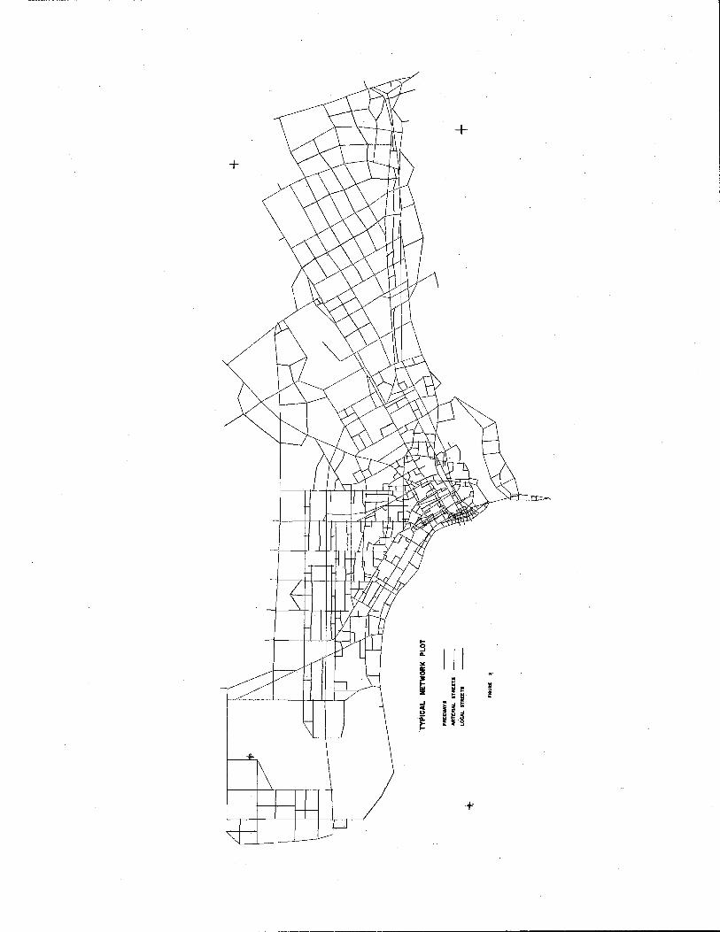
Automatic plotter line drawings of network configurations may be made quickly and more economically than similar maps drawn by draftsmen, By furnishing a library of node locations (in x, y coordinate form), a network description, and a network configuration 8 scaled line drawings may be accurately made ,
As reported by Arthur Sosslau (U o S. Department of Commerce, Bureau of Public Roads) 8 automatic plotting has the following advantages:
1 o Errors decrease since the plot is made directly from computer output.
2 0 Time for obtaining usable information decreases,
3. Technical Personnel are free for other work o
4, Tedious and boring jobs are eliminated 0
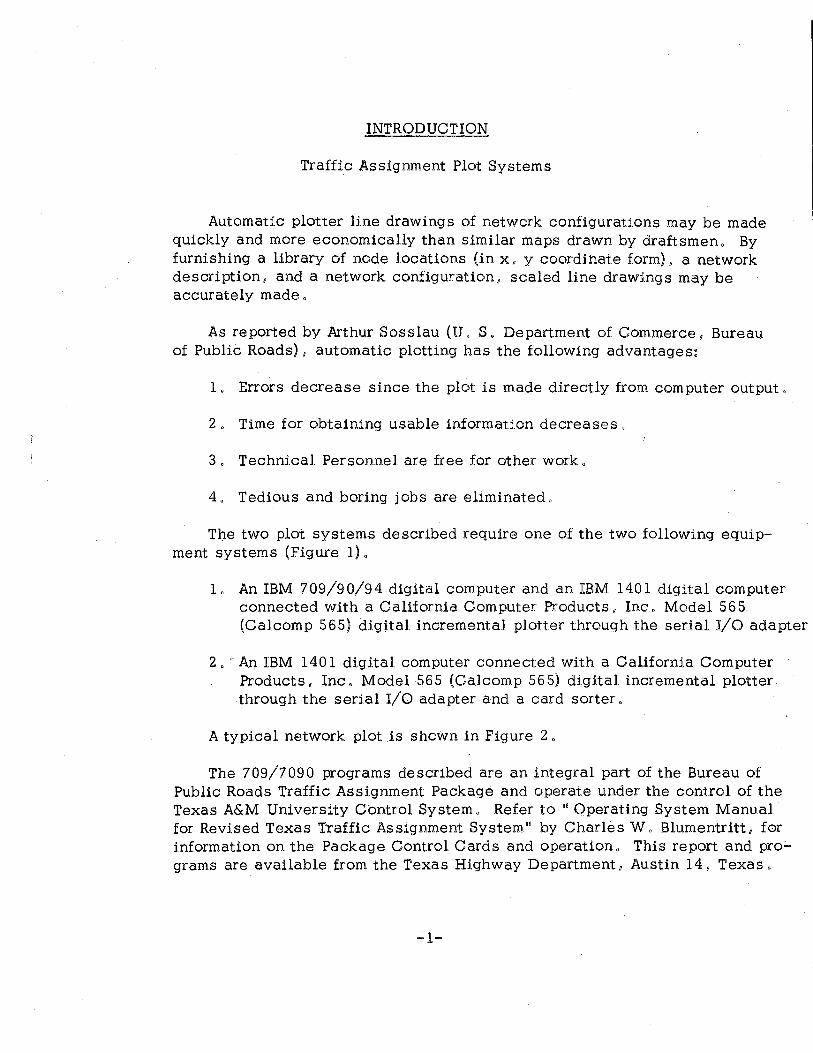
The two plot systems described require one of the two following equipment systems (Figure 1) .
1 0 An IBM 709/9 0/94 digital computer and an IBM 1401 digital computer connected with a California Computer Products, Inc. Model 565 (Calcomp 565) digital incremental plotter through the serial I/0 adapter ,
2. ' An IBM 1401 digital computer connected with a California Computer Products, Inc 0 Model 565 (Calcomp 565) digital incremental plotter. through the serial I/O adapter and a card sorter o
A typical network plot is shown in Figure 2 o
The 709/7090 programs described are an integral part of the Bureau of Public Roads Traffic Assignment Package and operate under the control of the Texas A&M University Control System o Refer to '"Operating System Manual for Revised Texas Traffic Assignment System'0 by Charles Wo Blumentritt, for information on the Package Control Cards and operation, This report and pro;.. grams are available from the Texas Highway Department, Austin 14 8 Texas o
-1-
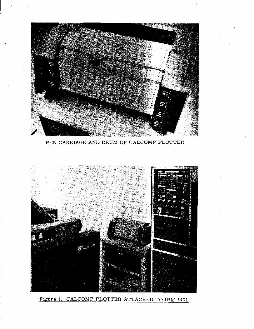
PEN CARRIAGE AND DRUM OF CALCOMP PLOTTER
Figure 1. CALCOMP PLOTTER ATTACHED TO IBM 1401
.... 3 ...
I I I "' "' ~ .... e 1&1 z II!. I _. • t; i "' i i t; u 1i: ~:~ e_~ I'= f !I


----------------------- ---- ------
GLOSSARY
Arterial: A class of street serving major movements of traffic not served by freeways. In traffic assignment, a link connecting two arterial nodes or an arterial and a freeway node is classified as an arterial link"
Centroid: A node in a network that is considered to be the point of origin or destination of trips for a zone,
Calcomp 565: · The automatic line plotting device, California Computer Products Model 565 digital incremental plotter, used in this study.
Coordinates: The coordinates of nodes used in plotting are in x, y coordinate form and are five digit integers. The map is considered to be in the upper right-hand quadrant with an origin as follows:
l. 709/7090 system: minimum x andy values as found in the coordinate library are used as the origin.
2. 140 l system: minimum x andy values are taken from the parameter card for origin definition,
Limits are x and y greater than zero and less than 32,767. The lon~ axis of the map $hould be the x~axis,,. ~. ,
·Desire Line: A straight line connecting the origin and destination of a trip. A desire line map is made up of many such desire lines, the color of which represents the number of trips moving between the origin and destination.
Destination: The zone in which a trip terminates,
Directional Plot:. A directional plot differs from a non-direction~! plot in that inbound and outbound traffic flow at an intersection are separated by . 02 inch on the plotted map.
Freeway: A divided arterial highway designed for the safe unimpeded movement of large volumes of traffic, with full control of access and grade separations at intersections, In traffic assignment, a link connecting two freeway nodes is classified as a freeway link.
Library (of coordinates): The card deck {or card image tape) of node location coordinates .
Link: A section of highway, identified by the nodes at its ends and described'
-4-

to the computer on a link card (link data card). A link may be one- or two-way.
Link Plot Data: Links to be plotted by the 1401 system. These data differ from link data in that only the existence of the link is determined by the card: flow information is not necessarily represented.
Loaded Network: A network on which the desired loads have been accumulated.
Local Street: A street intended only to provide access to abutting properties. In traffic assignment, any link having a centroid as one node.
Network: A network consists of nodes and links I and is a graphical representation of the physical facilities making up a transportation system.
Network Configuration: Any network or part of a network (i.e. a loaded network, a tree 1 etc.) .
Network Description: The numerical description of a highway network o Complete information is provided on system nodes I links, link travel impedances, and turn restrictions.
Node: A numbered point representing an intersection or zone centroid. Up to four links may be connected to each node 0 There are three types of nodes: centroid, arterial, and freeway. These types are identified by the magnitude of their numbers I the lowest being centroids, and the highest being freeways.
Street Type: The three classifications of urban streets are local, arterial, and freeway.
Strip: The network description map is divided into N equal strips by lines drawn parallel to the x-axis 0 These strips are scaled and plotted in eleven inch widths.
Trace: The minimum impedance route through a network from one centroid to another 0
Traffic Assignment: The process of determining route or routes of travel and loading centroid to centroid trips to these routes.
Tree: A tree is the aggregate of all the minimum path routings from one node to all other nodes in a network .
Zon~~ A ~ubclivi~ion of th~ 111tucly or ~urv~y ~r~~ which i!l! \Jill~ful in ~n~ly~h or cl~t~ coll~ction. Zon~~ m~y b~ !l!~qu~:nc~cl or un!ll~qu~nc~cl,
~5-

CHAPTER I
709/7090 Plot System
I. Identification: Bureau of Public Roads Traffic Assignment Package 1
Texas A&M University Control System:
Program 23: Plot Network Description Program 2 4: Plot Loaded Network Program 2 5: Plot Trees
Machine Requirements: IBM 709/90/94 IBM 1401 with serial I/O adapter Calcomp 565 (Refer to Chapter III for specific requirements)
II. Preliminary Considerations
The 709/90/94 programs described here were designed for use with the Bureau of Public Roads Traffic Assignment Package in conjuncUon with the Texas A&M University Control System,
The network configurations which may be plotted are a network description I a loaded network, or a tree. The input to the three programs is previously prepared binary network representations and a BCD tape of node locations (library of coordinates). The program output is a BCD tape to be used as input to a 1401 program (described in this chapter) which will plot the desi.red network representation (PTI).
"Operating System Manual for Revised Texas Traffic As si.gnment System" should be reviewed for preparation of control cards for the system. The following explanation of ·control cards pertains only to the plot programs·.
A. Control Cards for Programs 23 and 24
After either of the network plot programs (Plot Network Description or Plot Loaded Network) have been selected, the user may specify certain parameters~
1. Directional or non-directional plot
2. Number of strips for the plot
3. Street type selection
-6-
4. Volume range selection (Loaded Network, only)
5o Color selection for street type or volume range
The five control card types for the network programs (23 and 24) are:
1. Number Card: Specifies the number of plots to be made.
2. Type 1 Card: Specifies general i.nformatl.on for a plot.
3 o Type 2 Card: Color selection
4. Type 3 Card: Volume range selection (Loaded Network, only)
5o Type 4 Card: Street type selection
1. Number Card
A Number Card need not be used Jf only one plot is desired. If more than one plot is desired, use of the number card eliminates the need of recalling the plot program for each plot. The format of the Number Card is as follows:
Column Information
1-6 NUMBER (Required)
7-12 Number of plots to be made, right justified.
2. Type 1 Card
Every plot to be made requires a Type 1 card 0 This card allows the selection of the following options:
1. Directional or non-directional plot
2. Number of strips for this plot
3 . Number of colors for this plot
4. Street type specification option
5. Color specification option
-7-

There are also two fields of the Type 1 card which will enable the program to use information held in the machine from a previous plot rather than having the information read from tape unnecessarily 0
These fields are used in conjunction with a Number card, when more than one plot is being made at the same time 0
Type 1 Cards have the following format:
Column
1-6
7-12
13-18
24
30
36
42
48
54
3. Type 2 Card
Information
If a directional plot, DIRECT. If non-· directional, blank.
Number of strips for this plot, right justified 0
Number of colors for this plot, right justified,
If pen colors are specified, Co If pen colors are not specified, blank 0
If volume range specified, V. If no volume selection, blank.
If street type selection, N. If no street type selectionu blank.
If the network used for the previous plot is to be used forthis ploto ~0
If a different network i.s to be used, or if this is the first plot, blank o
If the library used on the previous plot is to be used for this plot, ~-
If a different library is to be used or H this is the first plot, blank o
l (required) o
If column 2 4 of control card Type 1 contains a C (Color option selected).~ a Type 2 card must be used 0 The colors 1, 2, 3, and 4 are those which will be used in plotting the street type specified, 1 through 4, and (or) the volume range specified, 1 through 4 o The format is~
-8-

Column Information -------
1-6 Color 1
7-12 Color 2
13-18 Color 3
19-24 Color 4
54 2 (Required)
The colors which may be specified are red, blue, green, and black, The word used as colors 1 through 4 is used in a message to the 1401 operator to change the pen color. For example, RED may be specified for Color 1, BLUE, for color 2.
4. Type 3 .Card
A Type 3 card, specifying volume range selection may not be used with Program 23, Plot Network Description, since volume flow information is not represented by the network descri.ption record., A Type 3 card is to be used if column 30 of the Type 1 card contains V (volume range option selected) and Program 24 is used. Type 3 cards have the following format:
Column
1-6 7-12
13-13 19-24
25-30 31-36
37-42 43-48
54
5. Type 4 Card
Information
Minimum volume and Maximum volume to be plotted ln Color 1 .
Minimum volume and Maxim·um volume t() be plotted jn Color 2.
lj:
Minimum volume and Maximum volume to be plotted in Color 3 ,
Minimum volume and Maximum volume to be plotted in Color 4"
l (required)
A Type 4 control card specifies which type of street (local, arterial, freeway) is to be plotted with a particular color (and a particular volume, if specified). Its format is:
-9-

Column Information
6 Street type for Color 1
12 Street type for Color 2
18 Street type for Color 3
24 Street type for Color 4
54 ! (required)
The street types are specified by an L, A, or F in the indicated column. L specifies local streets, ~J arterial streets, and F, freeways o
B. Program 2 5 Control Cards
The previous discussion pertains only to the control cards for the Plot Network Description and Plot Loaded Network Programs 0 If Prog-ram 2 5, Plot Trees, is specified, the following parameters m_ay be selected:
1. Number of strips for the trees 0
2, Color to use for the trees 0
3 , Trees to be plotted,
The control cards to specify these parameters are a Type T Card" and a Centroid Selection Card,
1.o Type T Card
The Type T card has the following format:
Column Information
1-6 Number of strips for the trees, right justified 0
7-12 Color for the trees to be plotted 0
54 T (required)
-10-
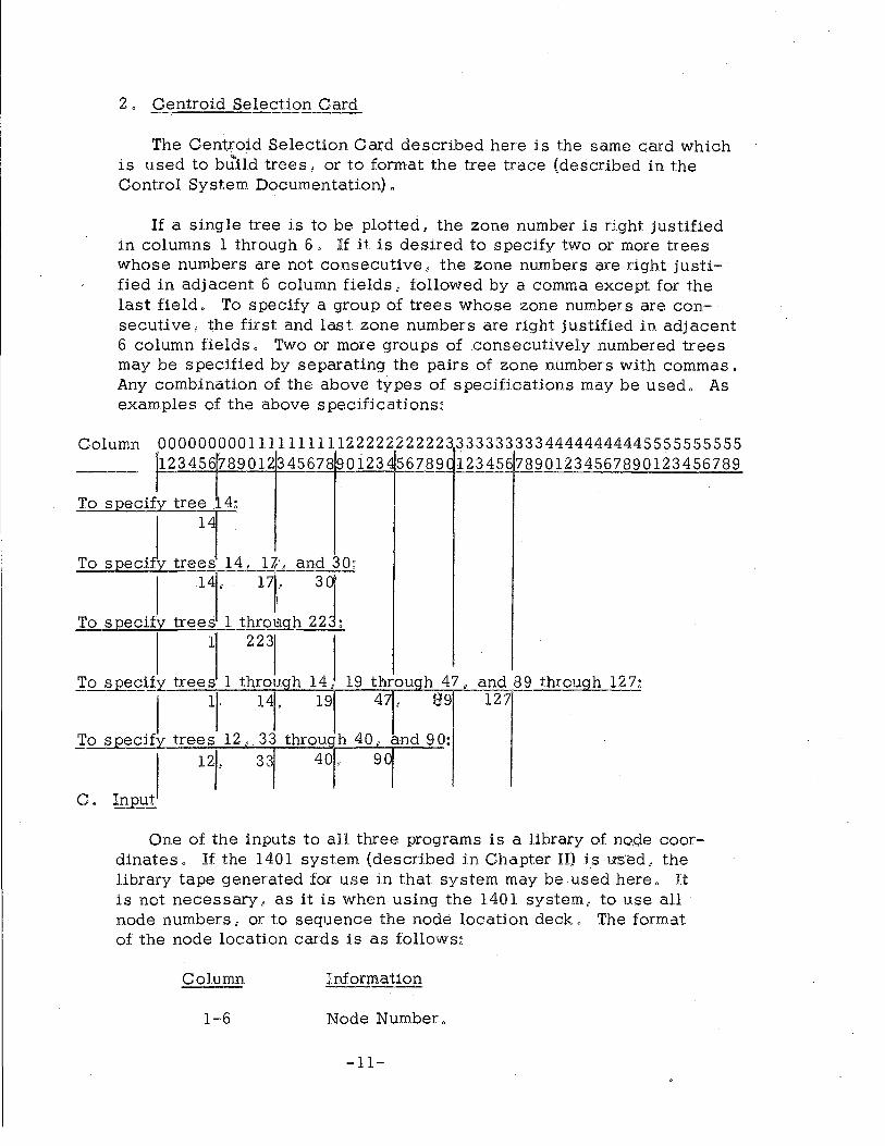
2 o Centroid Selection Card
The Centroid Selection Card described here is the same card which is used to bu"'ild trees, or to format the tree trace (described in the Control System Documentation).
If a single tree is to be plotted, the zone number is right justified in columns 1 through 6 o If it is desired to specify two or more trees whose numbers are not consecutive, the zone numbers are right justified i.n adjacent 6 column fields, followed by a comma except for the last field. To specHy a group of trees whose zone numbers are consecutive, the first and last zone numbers are right justified in adjacent 6 column fields o Two or more groups of consecutively numbered trees may be specified by separating the pairs of zone numbers with commas. Any combinati.on of the above types of specifications may be used. As examples of the above specifications~
Column 00000000011111111112222222222333333333344444444445555555555 . . h23456789 01234567890 i234 56789 c l23456 7890123456789 0123456 789 ---
1 . To specify tree . 4:
To speciJ tre:J 14, n, and 30:
I .14, 1l 3J To specil tree~ 1 t~~~rh 22 :
To specify trees 1 throuqh 14, 19 throuqh 47, and 89 through 127~
I 1l, ll 19 47, 99 127
To specify trees 12 33 throu~h 40, and 9Q:
12,, 331 401' 901
C. Input
One of the inputs to all three programs is a library of node coordinates. If the 1401 system (described in Chapter H) is us'E:!d, the library tape generated for use in that system may be used here 0 It is not necessary, as it is when using the 1401 system, to use all node numbers, or to sequence the node location deck. The format of the node location cards is as follows~
Column Information
1-6 Node Number o
-11-

Column Information
7-12 x coordinate •
13-18 y coordinate 0
(all figures right justified with leading zeroes)
The tape required as input is a card image tape 0
D. Output
Output from all three programs is a BCD tape, 1500 characters per record (250 words per record) o At the completion of a plot, the output tape is not rewound. Several plots may be written on the same output tape. In the event that an end of tape i.s reached on the output tape 8 a message is given on Une to the 709 operator instructing him to mount a new tape o and proceed.
III. Plot Network Description (Program 23)
The Network Description tape, built by Program 5 (Build Network Description) in the Traffic Assignment Package o contains link data: speed and time for all links in the network. The network may be plotted either in directional form or non-directional form, and street selection for multi-color plots may be made.
Method
The program reads the library of coordinates from the library tape on unit B3, As this information is being brought into core, the binary network representation is brought in from unit A2.
Network records are examined, and according to plot speci.fications (number of strips, type of street for each color) the link to be drawn is entered in a table, When all links to be drawn have been entered in the table, the 1500 character records are written on the output tape, A4. If there are more than 5,000 links to be drawn in the same color on the same strip, tape B5 is used for an intermediate tape: after all links in the table and records on the intermediate tape have been processed, the next color, or next strip" :ls plotted.
Input
Binary network description on A2 BCD library of coordinates on B3 Scratch tapes on units B5 and A4
-12-

Control cards in card reader Other units as specified by the control system document
Output
Plot tape on A4" (The 1401 program, PTI, described in this chapter is to be used for plotting the tape o)
IV. Plot Loaded Network (Program 24)
Operation of this program is the same as that for Program 23, except that volume range may be used as a plot criterion o This control may be used in conjunction with the street type selectiono For example, a four color :glot could be made of freeways, depending on four volume ranges 0
The network record used by this program is the loaded network record, built by Program 2, Load Minimum Paths"
Input.
Binary loaded network on B 1 BCD library of coordinates on B3 Scratch tapes on BS and A4 Control cards in card reader Other units as specified by the control system document
Output
Plot tape on A4. (The 1401 programo PTL described in this chapter is to be used for plotting the tape o)
V. Plot Trees (Program 25)
The tree records are buHt by Program 1 ·' Build Trees" Trees are formatted, and must be plotted in the order in which they were bui.lL All trees specified by the Centroid Selection Card are plotted in the number of strl.ps and in the color specl.fied by the 10 T11 Cardo
Method
The tree parameter cards are read, and a table of trees to be plotted is built from the Centroid Selection Card o Each tree is plotted from information on the tree tape on unit A3 o At the start of the program, the tape containing the library of coordinates is read into core, and then rewound" Every tree specified is plotted using the same library of coordinates 0
-13-
Binary tree tape on unit A3 BCD library of coordinates on B3 Scratch tape on unit A4 Control cards in card reader Other units as specified by the Control. System documentation 0
Output
Plot tape on A4 (The 1401 program, PTI, described in this chapter is to be used for plotting the tape o)
VI. Plotting of 709/90/94 Output: Plot Tape Interpreter (PTI)
The tape generated by the preceding programs is plotted by the 1401 program, Plot Tape Interpreter. Since several of the records of the output tape are specification records, the program is able to give messages to the 1401 operator concerning the color.of the pen to use, when ~o change the pen, and when the job is complete.
Method
The first record on the output tape has the following format:
Column Information
2-4
11-12 Number of strips for plot
13 .. Number of pen changes per strip
This information is gi vt!n on the pdnter at the start of the plot, along with instructions to the 1401 operator on plotter preparation and operation.
The next, and succeeding files on the tape, consi.st of one record indicating pen color, and following records of plot characters.
The plot characters are vyri.tten by the 709/90/94 program such that no pen change position is necessary by the 1401 operator.
' If at any time during the plotting of the output tape, H is desired to sus-
pend operation, sense switch B may be used for an interrupto It is extremely
-14-
important, however I that while other operations are being performed on the 1401, the pen position and plot tape position not be changed. To resume plotting 1 the plot program need only be reloaded.
Input
PTI program in card reader Plot tape on unit 1
Output
Network configuration plot
-15-

CHAPTER H
140 1 Plot Sy~te~
I, Identification~ Traffic Assignment Plot System.
Machines: IBM 1401 with serial I/O adapter Calcomp 565 (See Chapter II for specific machine requirements)
II. Preliminary Considerations
To plot a network configuration, link plot data must be avaHable in either card form (original link data cards may be used) or on a previously written IBM 709/90/94 output tape. Necessary also i.s a punched card library of node locations in x, y coordinate form "
The 140 l program package consists of three programs~ Utility, Phase 1 o
and Phase 2. The purpose of the Utility program is preparation of Hnk plot data cards from one of three 709/90/94 output tapes (generated by the Bureau of Public Roads Traffic Assignment Package), or the preparation of ·a library tape from the library cards o depending on the option taken. Phase 1 prepares link ends coordinates cards; Phase 2 plots the network configuration. Figure 3 shows the data flow from link data or output tape and coordinate cards to network configuration map.
III. Utility Program (UTIL}
The Utility program prepares a Hbrary coordinate tape from the coordinate cards or punches link plot data cards from previously wrltten 709/90/94 output tapes, dependi.ng on the opti.on chosen. Each option is taken by setting the sense switch indicated by the option name,
A. Option B~ Preparing the Library Tape
Phase 1 requires that all node numbers be assigned a set of coordinates, If all node numbers do not represent a node in the network configuration, it is not necessary to include these non-used nodes in the coordinate card set: Option B assigns a locati.on of (x, y) equal to {0, 0) to any undefined nodes. A library tape is wri.tten by this option for use in Phase 1, and a node~ coordinate listing is made, if desired. A check on the sequence of the node numbers of the input coordinate deck is made by this option. If any cards are not in sequence, the job is terminated and must be restarted. (The program need not be reloaded; pres sing start will conti.nue the processing.)
-16-

NODE COORDINATE CARDS
(MUST BE IN NODE SEQUENCE)
(OPTION 8)
1401 UTILITY
PARAMETER CARDS
COORDINATE LISTING
(OPTION C) (OPTION D) (OPTION E)
1401
1401 UTILITY
LINK PLOT
CARDS
1401 PHASE
LINK ENDS COORDINATES
1401 PHASE 2
NETWORK MAP
DATA FIGURE 3
FLOW
ORIGINAL LINK DATA
CARDS
SORT cc 1-5
Method
Library coordinate cards must have the following format:
Column Information
3-6 Node Number
8-12 X coordinate
13-18 y coordinate
(All fig.ures right justified with leading zeroes)
As each card of the library set is read, a check l.s made to l.nsure that the node number is higher than the last node number read. If a gap exists in the sequence, coordinates of (0, 0) are assl.gned to the missing nodes.
Card image records are written on the Ubrary tape in the card format above, As each record is written, it is also printed. This listing is suppressed if sense switch C is up. All nodes and locations are printed, including nodes assigned the (0, O) coordinate"
When the last card has been written on the tape, an end of file is written I and the tape is rewound. A message is gi.ven on the I!Jrinter indicating that the tape is ready for Phase 1o
If any nodes of the card deck are not in node sequence, a sequence error message is printed, the tape is rewound and the job must be re-started by reloading the coordinate deck 0 (The program need not be reloaded 0)
Input
Node coordinate deck
Output
Library of coordinates on unit 2 Listing of library (listing suppressed if Switch C is up)
B o Punch Link Data Options
Phase 1 requires, in addition to the node coordinate tape I a set of link plot data. These data may be the original link data or may be punched from the output of one of three 709/9 0/9 4 programs in the Bureau of Public Roads Traffic Assignment Package. The programs are Print Tri.p Volumes (Program 13), Print Link Data (Program 12), and Format Tree Trace (Program 11) •
-18-
The format of the data needed by Phase l is as follows~
Column Information
l-6 Origin node, right justified
7-12 Destination node, right justified
If the type of listing specified by the option is not found on the tape I a message that an incorrect switch setting or an incorrect tape has been used, is given on the printer.
The punch link plot data options will locate the correct output on·a tape with several of the 709/90/94 programse output, The correct section of the tape is found and handled as if it were the only file on the tape, as selected by the option chosen.
1. Option C: Punch Link Data from Print Trip Volumes Ta,ee {Program 13)
Since the information on this tape is interzonal trip desires, a plot of desire lines may be made from this 7 09/9 0/9 4 output,
Only certain node sequences of interzonal trips P'ay be desired by the program user. For this reason, a parameter card specifying the first and last zones to be punched is requiredo Only origins between the first and last zones specified are punched in the required link plot data format, The volume for the interzonal link is also punched in.:the card. This enables a sort to be made for a multi-colored plot.
If the node selected as the upper limit is too high, a message is given on the printer, and the maximum zone is changed to the maximum zone on the tape.
Method ·-... =·-·-=--.,..-··,..,..,-
The input tape is scanned for the interzonal trip desires from the zone specified as the lower limit. When this block is found, the records are examined which have a de stina.tion equal to the oti'gin zone plus one to a destination equal to the destination sp~;'H::!ified as the maximum zone. When all interzonal information has been proce1Hied from this block 1 the next origin zone is proce!Ols~Qd I again beginning with a destination equal to the origjn plus one and proceeding to~ the zone maximurn, When the ori.1;;Li zc ... ~e re-aches the maximum zone minus one 1 only one de stinatj on is considered; this interzonal desire is maximum zone minus one to maximum
-1!0-

zone" If an interzonal trip de sire is equal to zero, a card is not punched; otherwise, the volume is punched with the origin and destination zones in the following format:
Column Information
3-6 Origin zone number
8-11 Destination zone number
19-24 Interzonal trip desires
Input
Output tape from Print Trip Volumes, Program 13 Parameter Card
Output
Link Plot Data cards with interzonal volumes
2, Option D: Punch Link Plot Data from Print Link Data Tape (Program 12)
The Print Link Data (Program 12) output gives data in the form ·of node to node volumes, distance and speeds" Option D is used to punch cards representing origin-destination nodes for a network· ploto
Method
Cards are punched from the output tape in the following format:
Column Information
3-6 Origin node number
8-ll Destination node number
Since the plot will be non-directional, only the low to high . origin to destination links are punched"
Output from Print Link Data, Program 12
-20-

Output
Link plot data
3 . Option E: Punch Link Plot Data from Format Tree Trace (Program 11)
Several trees may be listed on the output tape. A parameter card is used to specify I in orders which trees are to be punched for the plot phases.
It is important that trees are specified in the order in which they appear on the output tape. The tree number is punched in all link plot data cards for identification purposes.
Method
A parameter card specifying the trees to be punched is needed. This is the same card used by the 709/9 0/9 4 Tree programs. See page 11 for the tree selection card format.
The format of the link plot data cards punched by this option is:
Column Information
3-6 Origin node number I right justified
8-11 Destination node number I right justified
The tape is scanned for the tree number specified. When all link plot data for that tree have been punched, another tree is selected ·and the tree specified is found and processed.· This process continues until all trees have been processed. When an end of file is reached on the tape I a message is given listing any remaining trees which were called for, and not found on the tape.
Input
Output tape from Format Tree Trace, Program 11 Parameter Card
Output
Link Plot Data Cards
IV. Phase I -• -21-

b
0
Phase 1 prepares link ends coordinate data for Phase 2 by matching link plot data cards with the node locations on the library tape. The program handles any number of links and any number of nodes. The coordinate cards punched by Phase 1 contain the following information: origin coordinates, destination coordinates, origin node number, and destination node number .
Method
Input to Phase 1 is the coordinate library tape (see Utility Option B) and link plot data cards (see Utility Other Options).
Cards in the following format are punched by Phase 1:
Column Information
1-5 Origin node abscissa
6-10 Origin node ordinate
11-15 Destination node abscissa
16-20 Destination node orginate
27-30 Origin node number
37-40 Destination node number
These cards are punched using the link plot data cards: 250 data cards are read, and the locations of the nodes required are obtained from the library tape. Node locations are read into core from the library tape, 100 locations at a time. Two tapes are needed as intermediate input/output for storage of coordinate data. This need occurs when only one of the nodes required by a particular link is in core at the same time. The value available is held on tape until the other node location is in core v At that time, the plot data card is punched. When all 250 links have been processed, another 250 are read. An asterisk (*) in column 1 of the last card is used to indicate that all link data have been read,
Node coordinate library on unit 1 Link plot data cards, followed by an asterisk card (* in Column 1).
Output
Link ends coordinates
-22-

V. Phase 2
For a semi-optimum pen movement during plotting, it is necessary to sort the coordinate data cards prepared by Phase 1 on card columns 1 through 5. This will insure that the pen moves to new origins successively in the positive x direction.
The data to be plotted may be drawn to a specified scale (map units per plot inch) or in a specified number of strips. The plot parameter card also calls for a minimum and maximum value of x and y to be plotted. Any link having an origin or destination outside the range specified is drawn to the boundaries specified.
A message at the start of the job gives the scale factor used (in inches per map unit) and the number of strips required for the job I when either a scale or a number of strips is specified.
It may be desired· to plot I on one strip, the entire network configuration. Sense switch B allows the option of having all links falling outside the specified range to be listed .. If this option is taken, all links which have an undefined node (x and y equal to 0) are listed.
If it is desired to plot groups of links in different colors I a card with an .asterisk (*) in column 1 should be inserted between the groups. The pen will move to the origin, and the computer will halt when this record is encountered. A message to the operator instructs him to change the pen color before proceedir-g. The operator must be instructed on which pen color to use at each halt.
Method
When more tp.an one strip is needed to fulfill the parameter requirements 1
the plot data is written on tape during the plotting of the first strip. At the completion of the first strip, the tape is rewound and succeeding strips are plotted from the tape. This tape may be used for other plots: the program accepts tape input if sense switch C is up. If desired, the cards may be loaded on tape before plotting: the tape generated by Phase 2 is simply a card image tape ended by a tape mark.
The parameter card used in Phase 2 has the following format:
Column Information
1-5 Minimum x value to plot
7-11 Maximum x value to plot
-23-

<>
~
Column
14-18
20-24
27
30-35
VI. User Responsibility
Information
Minimum y value to plot
Maximum y value to plot
If a number of strips will be specified 8 N If a scale factor will be specified, .§.
If column 2 '7 is N 8 this field contains the number of strips desired, right justified.
If column 2 '7 is..£_, this field contains the scale factor to be used, in map units per plot inch: XXX.XXX.
The chart on the following page gives information which must be supplied to the 1401 operator for plotting of a network configuration. Instruct the operator to use the Utility, Phase l, and Phase 2 programs; which sense switch settings to use, and where to obtain the required data.
The density of any tapes may be changed. The only requirement is that a tape may be read in only that density which it was written, Users of a 709 may have only low density input/ output. /09 0/9 4 users may have low or high density input/ output.
-24-

"-'.LBJ.\11..).!..11 L)VV.!...L\....J.LJ. J,.,.U.J.i..l..£.1.\!\,...AU J..nr.u U!\IJ..J..U
PROGRAM TO BE USED A B C D E IO 1 2 3 READER OUTPUT i
UTILITY ' Option B X X X Scratch Node Loca- Library Tape
tion coordi- and listing nates
Option B X X X X Scratch Node Loca- Library tape (no listing) tion coordi-
nates
Option C X X X Print Trip Parameter Link Plot Volumes Card Data Cards .. Output
Option D X X X Print Link Link Plot Data Out- Data Cards put
Option E X X X Format Tree Parameter Link Plot Trace Out- Card Data Cards put
Phase 1 X X Coordinate Scratch Scratch Link Plot Link Ends Library Data Cards, Coordinates
*Card Cards Phase 2
Card Input X xz X Scratch 3 Link Ends Plot Coordinates Error list2
Cards, and Tape Input X X: X X Link Ends Parameter Plot
Coordinates Card(s). 4 Error list2
Taoe -- ----------------·-··- ------
Notes: l. These cards may be sorted in order to obtain a multi-color plot. The desire line plot may be made to show
different volumes of flow; the links may be plotted in multi-color street type plot. 2. Sense Switch B allows all links falling completely outside the range specified to be printed. This should
only be used when one strip is to be plotted. 3. This tape is not needed when only one strip is to be plotted. 4. If different colors are to be plotted, an asterisk card (* in column 1) should be inserted between the groups
of link ends coordinates cards. X~ The indicated sense switch up; all others down.
,, ,., 0

CHAPTER III
Machine Requirements
The IBM 709/90/94 digital computer used must have the following configuration:
1. 32 768 position memory
2 • 2 Data Channels, A and B
3. 6 tape unit~ on each channel
4. Reader and Printer on channel A
The IBM 1401 digital computer used to interpret and plot the output tape must have the following configuration: (This is not the same as the requirements for the 1401 Plot System machine:•)
1. 4000 position memory
2. 1 tape drive
3. Index registers
4. Store Address Registers
5. Sense switches A-C
6. High- low- equal compare
7. Serial Input/Output adapter
J. Jl<lOl Adapter
The 1401 Plot System (TAM UPS) requires the following configuration for the 1401:
l. 4000 position memory
2. 3 tape drives
3, Index registers
4. Multiply-Divide
-26-

5. Store Address Registers •
6. High-Low-Equal compare
7 . Sense switches A-E
8. Serial Input/Output adapter
9. Jl40 l Adapter
10. Calcomp 565
•
-27-
..
0
CHAPTER IV
709 Operator Instructions
"Operating System Manual for Revised Texas Traffic Assignment System 11
should be reviewed for operation of the package. This publication is available from the Texas Highway Department, Austin 14, Texas.
Additional information for use of the plot programs is as follows~
Program 23
Network description on A2 (Binary) Coordinate library on B3 (BCD) Scratch tapes on BS and A4 Control cards in card reader Other units as specified by the control system
Output
Plot tape on A4
Program 24
Loaded network on B 1 (Binary) Coordinate library on B3 (BCD) Scratch tapes on BS and A4 Control cards in card reader Other units as specified by the control syst~m
Output
Plot tape on A4
Program 25
Tree tape on A3 (Binary) Coordinate library on B3 (BCD) Scratch tape on A4 Other units as specified by the control system
-28-

Output
Plot tape on A4
1401 Operator Instructions
I. When using the 709/90/94 plot system, the Plot Tape Interpreter (PTI) program is to be used 0 (Label: RTH,
1. Mount the output tape on unit 2 0
2, Load the program, press start to read last card.
3, Change the pen to the color specified and press start,
4 0 Follow directions given on the printer at all times.
5o Halts: All programmed halts give a printer message. At_ the end of a plot, to determine if another plot is on the tape, press start. A message will be given indicating the tape condition.
II. When using the 1401 plot system, the following instructions apply:
A. Utility Program (Label: UTIL)
To use any opti.on (B through E) 6 in this program 6 or several options in succe s si.on, the program need only be loaded once 0 Thereafter, the program rei.ntializes itself at the completion of each job and reloading is unnecessary.
1. Option B: Preparation of Library Tape
a. Input: Library card deck
b 0 Output: Library tape Library listing if Sense Switch C is down
c. Operation:
1) Sense switches A and B up.
2) If no listing is desired, sense switch C up.
3) Scratch tape on unit 2 o
4) Card deck (library coordinates) in card reader 0
-29-

5) Press start to read last card o
6) At end of job, remove and label tape G
d. Halts: (See Utility Program Halts)
1) If the card deck is not in sequence (columns 3-6) a halt will occur and a message printed showing the out-of- sequence node. At this time, correct the cards, place all cards back in the reader, ready tape 2 (which was rewound and unloaded), and press start,
2) When the last card has been written on tape, the tape is rewound and unloaded, and a message "END OF JOB" is written on the printer.
2. Option C: Punch Link Plot Data from Print Trip Volumes Tape
a, Input: Output tape from 709 Program 13 on unit 1 0
Parameter card in reader,
b. Output: Link Plot Data Cards
c. Operation:
1) Sense switches A and C up.,
2) Mount Tape on unit 1.
3) Place the parameter card in the reader, ready the printer, place blank cards in the punch, and press start.
d. Halts: (See Utility Program Halts)
3, Option D: Punch Link Data from Print Link Data Tape
a. Input: Output tape from 709 Prog-ram 12 on unit 1.
b. Output: Link Plot Data Cards
c. Operation:
1) Sense switches A and D up,
2) Mount tape on unit 1.
-30-

3) Ready the printer, place blank cards ln the punch, and press starto
d. Halts: (See Utility Program Halts)
4. Option E~ Punch Unk Plot Data from Format Tree Trace Tape
a 0 Input: Output tape from 709 Program 11 on unit 1. Parameter card(s) in card reader o
b o Output~ Li.nk Plot Data Cards Listing of any misslng trees (as specified by the parameter card) o
co 0 perati.on:
l) Sense sw;itches A and E up,
2) Mount tape on unit l o
3) Place card(s) in reader, ready the printer, place blank cards in the punch, and press starL
d, Halts~ (See Utility Pfogram Halts)
50 Utility Program Halts
a. After processing options C through E, a terml.nating message is given on the printer {'0 ALL DATA PROCESSED") and tape l is rewound and unloaded; Other options may be executed at this time without reloading the program~ set the switches as desired and press starL The I-address at this halt is 0468.
b o Tape Transmission Errors,
l) In case of tape transmission errors, either in reading or writing, the error routi.ne attempts to read or write until the error is established as permanent. At that time, a message is printed giving the error and unit. A start from thls halt retries the operati.on; if the error persists, the tape or tape unit is in need of mai.ntenance,
6 0 General Operati.on Points
a, In cases where a parameter card is to be read, the computer
-31-

fJ
will require an additional 18 Start" to read the last card, Observation of the operation register wi.ll indicate that the card has been read o or that the computer is sti.ll attempting to read the card (" 1" in the register),
b 0 In all questions of machine operation, consult the 1401 reference manual for instruction.
B. Phase l
L Mount the library tape on unit 1, and scratch tapes on units 2 and 3 0 The scratch tapes should be used at high density 0
2. Input:
a. Program, Phase l (Label: PH l) o
b 0 Link plot data cards "
c, Card with asterisk (*) in column l following data cards 0
3. Place blank cards in punch o press load.
4. Halts:
a. See TAPEI0 Halts,
b. A halt at an !-address of 819 is the end of job halL Thi.s is a non-recoverable halt: to restart the job, the program must be reloaded"
C. Phase2
1: Ready the plotter: the pen srould be 7 steps from the righthand side of the paper, and should be in a raised position.
2. Load the program, and if the input is:
a. Cards: place the cards in the reader.
b. Tape: Mount the tape on unit l, sense switch C up.
3. Operator messages are flagged: "OPERATOR*******". Other messages do not concern the operation of the program. At the end of the job, return the printer listing and the plotted output to the user.
-32-

4" At the start of a job, if the input is cards, a tape on unit 1 may be required" The computer will halt after a message is given so that the tape may be mountedo
50 If, during a job, a message is given for a pen color-change o
DO NOT move the pen from its present positi.on, or drop power on the plotter, Both of these warnings must be heeded--if not adhered to, the plot will not be as desired"
6" The program reinitializes itself at the end of job o Subsequent jobs need not have the program reloaded 0 Merely prepare the input and press starL
7 • Halts: (See TAPEIO Halts)
D " TAPEIO Halts
Phase 1 and Phase 2 use the same tape input/ output routine o If a halt occurs in either Phase 1 or Phase 2 and no message is given on the printer, check the A~ and B- address o
Permanent read errors halt with 22N in the A~ and B-addresses and write errors wHh 11N in the A- and B- addresses, where N indicates the tape unit on which the trouble is occurring 0 By pressing start" the transmission is retriedo If the damage i.s not correctable o the job must be restarted with a new tape,,
-33-
"")"
will require an additi.onal 15 Start 11 to read the last card 0
Observation of the operation register will indicate that the card has been read, or that the computer is sti.ll attempting to read the card (" l" in the register),
b. In all questions of machine operation, consult the 140 l reference manual for instruction.
B. Phase l
l. Mount the library tape on unit l, and scratch tapes on units 2 and 3. The scratch tapes should be used at high density.
2. Input:
a. Program, Phase l (Label: PHl)"
b. Link plot data cards 0
c. Card with asterisk(*) in column l following data cardso
3. Place blank cards in punch, press load o
4. Halts:
a. See TAPE!O Halts.
b. A halt at an !-address of 819 is the end of job halL This is a non-recoverable halt: to restart the job, the program must be reloaded.
C. Phase 2
1. Ready the plotter: the pen stould be 7 steps from the righthand side of the paper 1 and should be in a raised position.
2. Load the program I and if the input is:
a. Cards: place the cards in the reader.
b. Tape: Mount the tape on unit 1~ sense switch C up.
3. Operator messages are flagged: "OPERATOR******* 11• Other
messages do not concern the operation of the program. At the end of the job, return the printer listing and the plotted output to the user.
-32-

4, At the start of a job, :if the input is cards, a tape on unit l may be required" The computer will halt after a message is given so that the tape may be mounted 0
50 If, during a job,. a message is given for a pen color-change, DO NOT move the pen from its present position, or drop power on the plotter 0 Both of these warnings must be heeded--i.f not adhered to, the plot will not be as desired,
6" The program reini.tiali.zes itself at the end of job 0 Subsequent jobs need not have the program reloaded, Merely prepare the input and press starL
7 , Halts: (See TAPEIO Halts)
D o TAPEIO Halts
Phase 1 and Phase 2 use the same tape input/output routine o If a halt occurs in either Phase l or Phase 2 and no message is given on the printer, check the A- and B- address o
Permanent read errors halt with 22N in the A- and B-addresses and write errors with llN in the A- and B- addresses, where N indicates the tape unit on which the trouble is occurring, By pressing start, the transmission is retried" If the damage is not correctable, the job must be restarted with a new tape,
-33-
PUBLICATIONS
Project 2-8-63-60 Traffic Assignment
1 o Research Report 60-1 o "Texas A&M Traffic Assignment Link. Data Editor for IBM 1401 Data Processing System.u by Glenn N. Williams 0
2. Research Report 60-2, "Texas A&M Traffic Assignment Edit Print Trip Volumes for IBM 1401 Data Processing System" by William F o Pry 0
3. Research Report 60-3, "Traffic Assignment Plot Systems for IBM 1401 and IBM 709/90/94 Data Processing Systems" by William F. Pry o
