traffic engineering manual - florida … no. 750-000-005 march 1999 traffic engineering manual table...
TRANSCRIPT

TRAFFIC ENGINEERING MANUAL
February 2010

Chapter 1
ADOPTION PROCEDURE

Topic No. 750-000-005 March 1999 Traffic Engineering Manual Table of Contents Revised: July 2011
i-1
Chapter 1 PROCEDURE
Traffic Engineering Manual Adoption Procedure (Revised 3/24/09) ................... 1-1-1
Chapter 2
SIGNS 2.1 Use of Slippery When Wet Signs (Revised 12/22/06) ................................ 2-1-1
2.1.1 Conditions for Use .......................................................................... 2-1-1 2.1.2 Location and Placement ................................................................. 2-1-1 2.1.3 Notification ...................................................................................... 2-1-2
2.2 Overhead Street Name Signs (Revised 6/29/09) ....................................... 2-2-1 2.2.1 Purpose .......................................................................................... 2-2-1 2.2.2 Standards ....................................................................................... 2-2-1 2.2.3 Installation ...................................................................................... 2-2-2 2.2.4 Sign Design .................................................................................... 2-2-2
2.3 Signs and Markings at Divided Highways and Crossroads (Revised 12/22/06) ........................................................................................ 2-3-1
2.4 Symbol Signs on the State Highway System (Revised 12/22/06) ............. 2-4-1 2.4.1 Definitions ....................................................................................... 2-4-1 2.4.2 Conditions for Use .......................................................................... 2-4-1
2.5 Destination Distance Signs at Rural Interstate and Freeway Exit Ramp Terminals (Revised 12/22/06) ................................... 2-5-1 2.6 Bridge Signs and Markings (Revised 12/22/06) ......................................... 2-6-1
2.6.1 Bridge and Sign Structure Low Clearance Signs ............................ 2-6-1 2.6.2 Bridge Pier Marking ........................................................................ 2-6-1 2.6.3 Cross Road Name Signs on Overpasses ....................................... 2-6-1 2.6.4 Narrow Bridge Treatment ............................................................... 2-6-2
2.7 Place Name Signs on the State Highway System (Rescinded 4/7/05) (Now Part IV of Rule 14-51, F.A.C.) 2.8 Move Accident Vehicles from Travel Lanes Signs (Revised 12/22/06) .... 2-8-1
2.8.1 Sign Design .................................................................................... 2-8-1 2.8.2 Location and Placement ................................................................. 2-8-1
2.9 No Passing Zone Signs (Revised 12/22/06) ................................................ 2-9-1 2.10 Vending Machine Signs (Revised 12/22/06) ............................................. 2-10-1
2.10.1 Physical Characteristics ............................................................... 2-10-1 2.10.2 Location and Placement ............................................................... 2-10-1
2.11 Guidelines for Bicycle Warning Signs (Revised 12/22/06) ...................... 2-11-1 2.11.1 Definitions ..................................................................................... 2-11-1 2.11.2 General Instructions ..................................................................... 2-11-1 2.11.3 When Sign Requests May Be Approved ...................................... 2-11-2 2.11.4 Sign Design .................................................................................. 2-11-2 2.11.5 Sign Placement ............................................................................ 2-11-3
Topic No. 750-000-005 March 1999 Traffic Engineering Manual Table of Contents Revised: July 2011
i-2
2.12 Recycling Collection Center Signs (Revised 12/22/06) ........................... 2-12-1 2.12.1 Definition ...................................................................................... 2-12-1 2.12.2 Sign Design ................................................................................. 2-12-1 2-12-3 Sign Installation ............................................................................ 2-12-1
2.13 Signing for Safety Belt Use and Child Restraint Laws (Revised 12/22/06) ...................................................................................... 2-13-1 2.13.1 Purpose ........................................................................................ 2-13-1 2.13.2 Background .................................................................................. 2-13-1 2.13.3 State Highway System Points of Entry ......................................... 2-13-1 2.13.4 Rest Areas and Interstate Welcome Centers ............................... 2-13-1 2.13.5 Other Locations ............................................................................ 2-13-2 2.13.6 Standard Safety Belt Sign ............................................................ 2-13-3 2.13.7 Sign Design .................................................................................. 2-13-3 2.13.8 Sign Availability ............................................................................ 2-13-3
2.14 Signing Hurricane Evacuation Routes (12/22/06) .................................... 2-14-1 2.14.1 Purpose ........................................................................................ 2-14-1 2.14.2 Background .................................................................................. 2-14-1 2.14.3 Procedure ..................................................................................... 2-14-1 2.14.4 Sign Design .................................................................................. 2-14-2 2.14.5 Sign Use ....................................................................................... 2-14-2 2.14.6 Sign Placement ............................................................................ 2-14-3 2.14.7 Sign Installation ............................................................................ 2-14-3 2.14.8 Shelter and Traveler Information Signing ..................................... 2-14-3 2.14.9 Shelter Sign Design and Use ....................................................... 2-14-4 2.14.10 Traveler Information Signing Design and Use .............................. 2-14-4 2.14.11 Continuous Hinge Requirements .................................................. 2-14-7 2.14.12 Radio Frequency Information Signs ............................................. 2-14-7 2.14.12.1 Radio Frequency Information Sign Design .................. 2-14-7 2.14.12.2 Radio Frequency Information Sign Placement ............ 2-14-7 2.14.12.3 Radio Frequency Information Sign Installation ............ 2-14-9 2.14.13 Evacuation Sign Messages ........................................................ 2-14-10 2.14.13.1 Shoulder Operation .................................................. 2-14-10 2.14.13.2 Dynamic Message Signs (DMS) ............................... 2-14-12 2.14.13.3 Location of DMS and Static Signs ............................ 2-14-13
2.15 Smoke on Highway Signs (Revised 12/22/06) .......................................... 2-15-1 2.15.1 General ......................................................................................... 2-15-1 2.15.2 Temporary Smoke on the Highway Sign ...................................... 2-15-1 2.15.3 Prescribed Burn Sign .................................................................... 2-15-2 2.15.4 Sign Installation and Removal ..................................................... 2-15-3
2.16 Signing for Supplemental Guide Signs and Motorist Services on Limited and Non-Limited Access Highways (Rescinded 4/7/05) (Now Rule Chapter 14-51, F.A.C., Florida's Highway Guide Sign Program) 2.17 Emergency Highway Traffic Plan (Rescinded 4/6/09)
(Now Topic Number 500-000-104, Emergency Management Program)

Topic No. 750-000-005 March 1999 Traffic Engineering Manual Table of Contents Revised: July 2011
i-3
2.18 *FHP Highway Assistance Program (Revised 12/22/06) .......................... 2-18-1 2.18.1 Purpose ........................................................................................ 2-18-1 2.18.2 Sign Location ................................................................................ 2-18-1 2.18.3 Sign Design and Installation ......................................................... 2-18-1 2.18.3.1 Interstate and Other Limited Access Routes .............. 2-18-2
2.18.3.2 Major Arterial Routes .................................................. 2-18-2 2.18.4 Sign Availability ............................................................................ 2-18-2
2.19 Holding for Future Section 2.20 Call Box/Mile Marker Signs (Revised 12/22/06) ........................................ 2-20-1
2.20.1 Purpose ........................................................................................ 2-20-1 2.20.2 Installation .................................................................................... 2-20-1 2.20.3 Sign Design .................................................................................. 2-20-1
2.21 Florida Litter Law Signs (Revised 12/22/06) ............................................. 2-21-1 2.21.1 Purpose ........................................................................................ 2-21-1 2.21.2 Sign Design and Placement ......................................................... 2-21-1 2.21.3 Sign Installation ............................................................................ 2-21-2
2.22 Traffic Control for Toll Collection Facilities (Rescinded 4/13/09) (Now included in Turnpike Plans Preparation and Practices Handbook) 2.23 Florida's Turnpike and Toll Road Numbering and Signing Program (Revised 12/22/06) ...................................................................................... 2-23-1
2.23.1 Purpose ........................................................................................ 2-23-1 2.23.2 Background .................................................................................. 2-23-1 2.23.3 Road Numbering Program ............................................................ 2-23-1 2.23.4 Signing Program ........................................................................... 2-23-2 2.23.5 Recommended Maximum Trailblaze Distance ............................. 2-23-4 2.23.6 Limited Access Sign Designs ....................................................... 2-23-4
2.24 Placement of Crime Watch Signs on the State Highway System (Revised 12/22/06) ...................................................................................... 2-24-1
2.24.1 Purpose ........................................................................................ 2-24-1 2.24.2 Definitions ..................................................................................... 2-24-1 2.24.3 Background .................................................................................. 2-24-1 2.24.4 Requests for Signing .................................................................... 2-24-1 2.24.5 Sign Locations .............................................................................. 2-24-2 2.24.6 Sign Design and Placement ......................................................... 2-24-2 2.24.7 Installation and Maintenance ........................................................ 2-24-3 2.24.8 Special Considerations ................................................................. 2-24-3
2.25 Distance Signing for Non-Limited Access Highways (New 9/7/99) ........ 2-25-1 2.25.1 Purpose ........................................................................................ 2-25-1 2.25.2 Background .................................................................................. 2-25-1 2.25.3 Procedure ..................................................................................... 2-25-1
2.26 Advance Guide Signs on Limited Access Highways (Revised 12/22/06) ...................................................................................... 2-26-1
2.26.1 Purpose ........................................................................................ 2-26-1 2.26.2 Background .................................................................................. 2-26-1 2.26.3 Definitions ..................................................................................... 2-26-1 2.26.4 Procedure ..................................................................................... 2-26-1

Topic No. 750-000-005 March 1999 Traffic Engineering Manual Table of Contents Revised: July 2011
i-4
2.27 Commuter Assistance Signs (Revised 12/22/06) ..................................... 2-27-1 2.27.1 Purpose ........................................................................................ 2-27-1 2.27.2 Background .................................................................................. 2-27-1 2.24.3 Sign Design and Installation ......................................................... 2-27-1
2.28 Mile-Markers Along Arterial Highways (Revised 12/22/06) ..................... 2-28-1 2.28.1 Purpose ........................................................................................ 2-28-1 2.28.2 Background .................................................................................. 2-28-1 2.28.3 Standards ..................................................................................... 2-28-1 2.28.4 Criteria for Route Selection .......................................................... 2-28-2
2.29 Use of Fluorescent Yellow-Green Sheeting (Revised 12/22/06) ............. 2-29-1 2.29.1 Purpose ........................................................................................ 2-29-1 2.29.2 Criteria .......................................................................................... 2-29-1 2.29.2.1 Pedestrian Crossing Signs ............................................ 2-29-1 2.29.2.2 Bicycle Crossing Signs .................................................. 2-29-2 2.29.2.3 School Bus Stop Ahead Warning Signs ........................ 2-29-2 2.29.3 Application .................................................................................... 2-29-2
2.30 One-Stop Career Center Signs (Revised 12/22/06) .................................. 2-30-1 2.30.1 Purpose ........................................................................................ 2-30-1 2.30.2 Background .................................................................................. 2-30-1 2.30.3 Definitions ..................................................................................... 2-30-1 2.30.4 Sign Design and Installation ......................................................... 2-30-1
2.31 Unique Transportation Symbol Signs (Revised 12/22/06)....................... 2-31-1 2.31.1 Purpose ........................................................................................ 2-31-1 2.31.2 Background .................................................................................. 2-31-1 2.31.3 Scope ........................................................................................... 2-31-1 2.31.4 Passenger Ship Sign .................................................................... 2-31-1 2.31.5 Amtrak Sign .................................................................................. 2-31-2 2.31.6 Greyhound Sign ........................................................................... 2-31-3 2.31.7 Installation and Placement ........................................................... 2-31-4
2.32 511 Telephone Service Sign (Revised 12/22/06) ...................................... 2-32-1 2.32.1 Purpose ........................................................................................ 2-32-1 2.32.2 Sign Design and Placement ......................................................... 2-32-1 2.32.2.1 Interstate and Other Limited Access Routes .................. 2-32-2 2.32.2.2 Major Arterial Routes ...................................................... 2-32-2
2.33 Signing for Nature-based Tourism and Heritage Tourism Trails (Revised 12/22/06) ...................................................................................... 2-33-1
2.33.1 Purpose ........................................................................................ 2-33-1 2.33.2 Background .................................................................................. 2-33-1 2.33.3 Pilot Program ................................................................................ 2-33-1 2.33.4 Criteria for Signing Program ......................................................... 2-33-2 2.33.5 DOT Participation ......................................................................... 2-33-2 2.33.6 Sign Approval and Design ............................................................ 2-33-3 2.33.7 Sign Maintenance ......................................................................... 2-33-4

Topic No. 750-000-005 March 1999 Traffic Engineering Manual Table of Contents Revised: July 2011
i-5
2.34 Signing for the Florida Scenic Highways Program and the National Scenic Byways Program (Revised 12/22/06) ...................... 2-34-1
2.34.1 Purpose ........................................................................................ 2-34-1 2.34.2 Background .................................................................................. 2-34-1 2.34.3 Program Coordination .................................................................. 2-34-2 2.34.4 Sign Criteria .................................................................................. 2-34-2 2.34.5 Florida Scenic Highways Signs .................................................... 2-34-3 2.34.5.1 Coordination ................................................................... 2-34-3 2.34.5.2 Sign Detail ...................................................................... 2-34-3 2.34.5.3 Sign Installation .............................................................. 2-34-3 2.34.5.4 Maintenance ................................................................... 2-34-5 2.34.6 National Scenic Byway Signs ....................................................... 2-34-5 2.34.6.1 Coordination ................................................................... 2-34-5 2.34.6.2 Sign Detail ...................................................................... 2-34-6 2.34.6.3 Sign Installation .............................................................. 2-34-6 2.34.6.4 Maintenance ................................................................... 2-34-7
2.35 Signing for Memorial Roadway Designations (New 7/10/06) .................. 2-35-1 2.35.1 Purpose ........................................................................................ 2-35-1 2.35.2 Background .................................................................................. 2-35-1 2.35.3 Signing Process ........................................................................... 2-35-1 2.35.4 Sign Installation and Maintenance ................................................ 2-35-2 2.35.5 Sign Design .................................................................................. 2-35-2
2.36 Wayfinding Signs (New 4/19/07) ................................................................ 2-36-1 2.36.1 Purpose ........................................................................................ 2-36-1 2.36.2 Background .................................................................................. 2-36-1 2.36.3 Standards ..................................................................................... 2-36-1 2.36.4 Implementation Process ............................................................... 2-36-2 2.36.5 FHWA Request to Experiment ..................................................... 2-36-2
2.37 Advance Street Name Signs (Revised 4/19/09) ........................................ 2-37-1 2.37.1 Purpose ........................................................................................ 2-37-1 2.37.2 Background .................................................................................. 2-37-1 2.37.3 Definitions ..................................................................................... 2-37-1 2.37.4 Standards ..................................................................................... 2-37-1 2.37.5 Installation .................................................................................... 2-37-3 2.37.6 Sign Design .................................................................................. 2-37-3
2.38 Use of Temporary Stop Signs at Non-Functioning Signalized Intersections (New 5/17/07) ..................................................... 2-38-1
2.38.1 Purpose ........................................................................................ 2-38-1 2.38.2 Conditions for Use ........................................................................ 2-38-1 2.38.3 Locations and Placement ............................................................. 2-38-1 2.38.4 Storage and Distribution ............................................................... 2-38-2 2.38.5 Removal and Recovery ................................................................ 2-38-2
2.39 Warning, Stop, and Yield Sign Sizes (Revised 10/23/07) ........................ 2-39-1 2.39.1 Introduction ................................................................................... 2-39-1 2.39.2 Recommended Warning Sign Sizes ............................................. 2-39-1 2.39.3 Recommended Stop Sign Sizes ................................................... 2-39-3 2.39.4 Recommended Yield Sign Sizes .................................................. 2-39-5
Topic No. 750-000-005 March 1999 Traffic Engineering Manual Table of Contents Revised: July 2011
i-6
2.40 Displaying Messages on Dynamic Message Signs Permanently Mounted on the State Highway System (New 8/5/08) ........ 2-40-1
2.40.1 Purpose ........................................................................................ 2-40-1 2.40.2 Background .................................................................................. 2-40-1 2.40.3 Definitions ..................................................................................... 2-40-1 2.40.4 Approved Standard Safety Messages for Display on Permanently Mounted DMS ......................................................... 2-40-1
Chapter 3 SIGNALS
3.1 Signalized Intersection Flashing Mode Operation and Flashing Beacons (Revised 12/23/09) ....................................................... 3-1-1
3.1.1 Definitions ....................................................................................... 3-1-1 3.1.2 Recommendations for Signalized Intersections .............................. 3-1-1
3.1.2.1 Programmed Flashing Mode Operation .......................... 3-1-1 3.1.2.2 Non-Programmed Flashing Mode Operation .................. 3-1-2
3.1.3 Application Requirements for Signalized Intersection..................... 3-1-2 3.1.4 Heads to be Flashed ...................................................................... 3-1-3 3.1.5 Flashing Indication Colors .............................................................. 3-1-3 3.1.6 Application Requirements for Flashing Beacons ............................ 3-1-4 3.1.7 Operation of Flashing Beacons ...................................................... 3-1-4
3.2 Guidelines for Left Turn Treatment (Revised 12/23/09) ............................. 3-2-1 3.2.1 Purpose .......................................................................................... 3-2-1 3.2.2 Left Turn Signal Phasing ................................................................ 3-2-1 3.2.3 Left Turn Signal Displays ................................................................ 3-2-3 3.2.4 Signal Display for Exclusive Left Turn Lane ................................... 3-2-3 3.2.5 Left Turn Phases for Separated Left and Thru Lanes..................... 3-2-3 3.2.6 Permissive Only Mode in Multi-Left Turn Approaches .................... 3-2-6
3.3 Scheduling Traffic Signal Studies and Funding Arrangements (New 3/93) ...................................................................................................... 3-3-1
3.3.1 Purpose .......................................................................................... 3-3-1 3.3.2 General ........................................................................................... 3-3-1 3.3.3 Response to Signal Requests and Scheduling Traffic Signal Studies .................................................................... 3-3-1 3.3.4 Traffic Signal Studies and Engineering ........................................... 3-3-2 3.3.5 Funding Arrangements for Warranted New Signal Installations ..... 3-3-3 3.3.6 Other Considerations ...................................................................... 3-3-4
3.4 Emergency Traffic Control Signals (New 2/3/10) ....................................... 3-4-1 3.4.1 Purpose .......................................................................................... 3-4-1 3.4.2 Background .................................................................................... 3-4-1 3.4.3 Procedure ....................................................................................... 3-4-1 3.4.4 Configuration and Operation of Emergency Traffic Control Signals ............................................................................. 3-4-2 3.4.5 Emergency Signal Sign ................................................................. 3-4-3 3.4.6 Other Requirements ....................................................................... 3-4-3
Topic No. 750-000-005 March 1999 Traffic Engineering Manual Table of Contents Revised: July 2011
i-7
3.5 Traffic Signal Mast Arm Support Boundaries (New 2/15/10) ..................... 3-5-1 3.5.1 General ........................................................................................... 3-5-1 3.5.2 Implementation ............................................................................... 3-5-1
3.5.2.1 Mast Arm Structures Boundary Maps ............................. 3-5-1 3.6 Standardization of Yellow and All-Red Intervals for Signalized Intersections (Revised 7/7/11)................................................. 3-6-1
3.6.1 Purpose .......................................................................................... 3-6-1 3.6.2 Standard ......................................................................................... 3-6-1
3.6.2.1 Yellow Change Interval ................................................... 3-6-2 3.6.2.2 All-Red Clearance Interval ............................................... 3-6-3 3.6.2.3 Turn Phases .................................................................... 3-6-3
3.7 Audible Pedestrian Signals (New 2/29/03) .................................................. 3-7-1 3.7.1 Purpose .......................................................................................... 3-7-1 3.7.2 General ........................................................................................... 3-7-1 3.7.3 Procedure ....................................................................................... 3-7-1 3.7.4 Approval/Denial Process ................................................................ 3-7-2
3.8 Mid-Block Pedestrian Crosswalks (Revised 1/5/10) .................................. 3-8-1 3.8.1 Purpose .......................................................................................... 3-8-1 3.8.2 General ........................................................................................... 3-8-1 3.8.3 Definitions ....................................................................................... 3-8-1 3.8.4 Procedure ....................................................................................... 3-8-2 3.8.5 Installation Criteria and Considerations .......................................... 3-8-3 3.8.6 Mid-block Pedestrian Crossing Treatments .................................... 3-8-6 3.8.7 Selection Guidance for Additional Treatments ............................. 3-8-12
3.9 Countdown Pedestrian Signal Head Applications (Revised 3/1/07) ......... 3-9-1 3.9.1 Purpose .......................................................................................... 3-9-1 3.9.2 General ........................................................................................... 3-9-1 3.9.3 Installation Criteria .......................................................................... 3-9-1 3.9.4 Installation/Removal Process ......................................................... 3-9-2
Chapter 4 MARKINGS
4.1 Crosswalks in Heavy Pedestrian Concentration Areas (Revised 8/5/04) 4-1-1
4.1.1 General ........................................................................................... 4-1-1 4.1.2 Markings ......................................................................................... 4-1-1 4.1.3 Signing ........................................................................................... 4-1-1
4.2 Lane Use Arrow and "ONLY" Pavement Markings on Intersection Approaches (New 6/91) ................................................... 4-2-1
4.2.1 General ........................................................................................... 4-2-1 4.3 Use of Blue Raised Pavement Markers to Identify Fire Hydrants (New 7/98) ...................................................................................................... 4-3-1
4.3.1 Purpose .......................................................................................... 4-3-1 4.3.2 Background .................................................................................... 4-3-1 4.3.3 Procedure ....................................................................................... 4-3-1 4.3.4 Guidelines ...................................................................................... 4-3-2

Topic No. 750-000-005 March 1999 Traffic Engineering Manual Table of Contents Revised: July 2011
i-8
4.4 Roundabout Markings (New 7/26/07) .......................................................... 4-4-1 4.4.1 General ........................................................................................... 4-4-1 4.4.2 White Lane Line Pavement Markings for Roundabouts .................. 4-4-2 4.4.3 Edge Line Pavement Markings for Roundabouts ........................... 4-4-2 4.4.4 Yield Lines for Roundabouts .......................................................... 4-4-3 4.4.5 Crosswalk Markings at Roundabouts ............................................. 4-4-3 4.4.6 Pavement Word and Symbol Markings for Roundabouts ............... 4-4-3 4.4.7 Example Markings for Roundabouts ............................................... 4-4-4 4.4.8 Markings for Other Circular Intersections ....................................... 4-4-4
Chapter 5 TRAFFIC OPTIMIZATION
5.1 Computer Models for Traffic Engineering and ITS Analysis and Design (Removed from Manual - Under Extensive Revision)
Chapter 6
SAFE MOBILITY FOR LIFE PROGRAM
6.1 Florida’s Elder Road User Program (Replaced 4/17/07) (Now Safe Mobility for Life Program on Web site at: www.dot.state.fl.us/TrafficOperations/Operations/SafetyisGolden.shtm) 6.2 Warning, Stop, and Yield Sign Sizes to Accommodate the Elder Roadway User in Florida (Replaced 4/17/07) (Now Section 2.39 Warning, Stop, and Yield Sign Sizes) 6.3 Intersection Guide Signs (Replaced 4/17/07) (Now Section 2.37 Advance Street Name Signs)
Chapter 7 CERTIFICATION AND APPROVAL OF TRAFFIC CONTROL
SIGNALS AND DEVICES
7.1. Approved Product List Certification and Approval Process (Revised 3/18/11) .......................................................................................... 7-1-1
7.1.1 Purpose .......................................................................................... 7-1-1 7.1.2 Authority ......................................................................................... 7-1-1 7.1.3 Definitions ....................................................................................... 7-1-1 7.1.4 Granting Certification or Approval .................................................. 7-1-3 7.1.5 Temporary Permit Process ............................................................. 7-1-4 7.1.6 Maintaining APL Certification or Approval ...................................... 7-1-5 7.1.7 Extending Certification or Approval ................................................ 7-1-6 7.1.8. Suspending and Withdrawing Certification or Approval .................. 7-1-6
HISTORY INDEX

Topic No. 750-000-005 March 1999 Traffic Engineering Manual Procedure Revised: March 2009
Traffic Engineering Manual Adoption Procedure 1-1-1
TRAFFIC ENGINEERING MANUAL ADOPTION PROCEDURE
PURPOSE: To provide traffic engineering standards and guidelines to be used on the State Highway System by the Department's District Traffic Operations Offices.
AUTHORITY: Chapters 316 and 334, Florida Statutes (F.S.) Rule 14-15.010, F.A.C., Manual on Uniform Traffic Control Devices (MUTCD)
SCOPE: This manual affects the State Traffic Engineering and Operations Office, District Traffic Operations Offices, and anyone else affected by traffic engineering standards and guidelines.
REFERENCE: Topic No. 025-020-002, Standard Operating System.
1. DISTRIBUTION
The official recipient of this manual will be the District Traffic Operations
Engineers and their employees, and the State Traffic Engineering and Operations Office managers and staff. The manual is available free of charge for informational purposes on the Internet.
1.1 AVAILABILITY
This manual is available free of charge at the Department's State Traffic Engineering and Operations Office website:
http://www.dot.state.fl.us/TrafficOperations/Operations/Studies/TEM/TEM.shtm
2. REGISTRATION
Users of the Traffic Engineering Manual interested in receiving automatic notifications of revisions to the manual by email may subscribe from the web site.
Topic No. 750-000-005 March 1999 Traffic Engineering Manual Procedure Revised: March 2009
Traffic Engineering Manual Adoption Procedure 1-1-2
As required by Section 283.55, F.S., by March 1 of each odd-numbered year, we will survey e-mail addresses from our current registration list and purge any outdated registrations.
3. REVISIONS AND ADDITIONS
3.1 The District Traffic Operations Engineers and the State Traffic Operations Engineer will constitute the Manual Review Committee.
3.2 Items warranting immediate change will be made with the approval of the State
Traffic Operations Engineer (after a majority vote of the Manual Review Committee and consultation with any other affected parties). Statewide meetings of District Traffic Operations Engineers will be held every six months, and a major agenda item will be any additions/changes either necessary or recommended to the manual.
3.3 All revisions will be coordinated through the Forms and Procedures Office prior to
implementation. 3.4 Substantive revisions or policy-related issues, as determined by the Manual
Review Committee, will be approved by the Secretary following the process established in the Standard Operating System, Topic No. 025-020-002.
3.5 Once revisions and/or additions have been approved by the Secretary they will
be posted on the Department's State Traffic Engineering and Operations Office website.
An e-mail notification will be made to all registered holders of the manual that the
revisions have been posted on the website.
4. TRAINING
None required.
5. FORMS
None required.

Chapter 2
SIGNS

Topic No. 750-000-005 March 1999 Traffic Engineering Manual Signs Revised: December 2006
Use of Slippery When Wet Signs 2-1-1
Section 2.1
USE OF SLIPPERY WHEN WET SIGNS
2.1.1 CONDITIONS FOR USE
The District Traffic Operations Engineer shall request the District Maintenance Engineer to erect SLIPPERY WHEN WET (W8-5) signs at locations where it has been determined there is a slippery pavement condition. A slippery pavement is defined when a standard friction test at 40 mph has determined the skid numbers are less than 25. When the posted highway speed is above 45 mph, SLIPPERY WHEN WET signs should be installed when the skid numbers are less than 30, and also one of the following conditions is met: • When the Safety Ratio (Actual Crash Rate divided by the Critical Crash Rate) is
greater than or equal to one. • Any downgrade greater than 3 percent. • At intersections with traffic signals.
2.1.2 LOCATION AND PLACEMENT
Additional signs may be needed at locations with the following conditions: (1) Horizontal Curves. SLIPPERY WHEN WET signs are to be placed prior to the
CURVE sign with an advisory speed plate. The ball-bank indicator provides a reasonable speed through the curve; however, a lower speed may be desired if there are known extraordinary hazards such as hydroplaning.
(2) Hydroplaning. Generally, hydroplaning only occurs at speeds above 47 mph;
however, excessive runoff across travel lanes may produce hydroplaning at lower speeds. Multi-lane facilities, rutted lanes, built-up shoulders, and downgrades are candidate locations. If excessive water buildup cannot be corrected, then SLIPPERY WHEN WET signs may be appropriate even when skid numbers are greater than 30.
(3) Ramp and Bridge Decks. Interchange exit or entrance ramps on sharp curves
and on a downgrade may present a hazardous condition if the pavement is also slippery. Special attention should be given to ramps with compound curves. A pavement friction inventory is normally maintained for interchange ramps; however, special tests, at speeds less than 40 mph can be requested.

Topic No. 750-000-005 March 1999 Traffic Engineering Manual Signs Revised: December 2006
Use of Slippery When Wet Signs 2-1-2
SLIPPERY WHEN WET signs should be used with an advisory exit speed sign, RAMP XX MPH (W13-2).
SLIPPERY WHEN WET signs shall be placed in advance of all moveable and
non-moveable steel deck bridges. These signs should be placed in accordance with Table 2C-4, Guidelines for Advance Placement of Warning Signs in the MUTCD (English Units).
2.1.3 NOTIFICATION
(1) The District Maintenance Engineers will promptly notify in writing the District Traffic Operations Engineer when SLIPPERY WHEN WET signs have been erected.
(2) The District Traffic Operations Engineer shall request the District Maintenance
Engineer to remove SLIPPERY WHEN WET signs that are no longer warranted under the above provisions.

Topic No. 750-000-005 March 1999 Traffic Engineering Manual Signs Revised: June 2009
Overhead Street Name Signs 2-2-1
Section 2.2
OVERHEAD STREET NAME SIGNS
2.2.1 PURPOSE
Street name guide signs for most streets that intersect with a road on the State Highway System are normally furnished, installed, and maintained by the appropriate local government. However, at signalized intersections on the State Highway System, larger overhead street name signs should be used. These signs may be furnished and installed, by the Department.
2.2.2 STANDARDS
(1) Street name signs shall only be used to identify cross streets. They are not intended to identify destinations such as cities or facilities.
(2) The word Street, Boulevard, Avenue, etc., may be abbreviated or deleted to
conserve sign panel length. However, if confusion would result due to similar street names in the area, for example Seminole Street and Seminole Avenue, this deletion should not be made.
(3) When a cross street is known by both route number and a local name, use of the
local name is preferred on the overhead street name signs since the route number is identified on route markers along the route.
(4) When a cross street has dual local street name designations, for example N.W.
31 Avenue and Martin Luther King Jr. Boulevard, both names may be used on the overhead street name signs. However, the Department is responsible for the primary designation (i.e., name shown on the Official Florida Transportation Map). If a secondary designation is approved by local resolution, the local government shall be responsible for the installation of this secondary designation.
(5) When a cross street has a different name on each side of the intersection, both
names shall be shown on the overhead street name sign, two signs should be used with one on the left and one on the right side of the intersection. In some instances, the type of signal span design may dictate the need for the use of a single sign with both names. When used, the names should be separated and accompanied by directional arrows, with the left name displayed over the right.

Topic No. 750-000-005 March 1999 Traffic Engineering Manual Signs Revised: June 2009
Overhead Street Name Signs 2-2-2
(6) The display of block numbers is not required when two street names with arrows are provided on a single panel.
2.2.3 INSTALLATION
(1) The location of the overhead street name sign on a signal strain pole and/or mast
arm may vary. However, it shall not interfere in any way with the motorist view of the signal heads.
(a) For static signs, the preferred installation is shown in the Department's
Design Standards, Index No. 17356. (b) For internally illuminated signs, the preferred installation is shown in the
Department's Design Standards, Index No. 17748. (2) In the case of separate street names on each side of the street, one sign should
be placed to the right of the centerline and signal heads and the other to the left side of the centerline and signal heads.
2.2.4 SIGN DESIGN
(1) Overhead street name signs shall be designed in accordance with Section
2D.38 of the MUTCD. (2) The sign panel used for overhead street name signs shall be 24 inches in height
with length determined by legend. (3) At a minimum, 8-inch upper and 6-inch lower case lettering for the street name
and 6-inch all upper case lettering for the block numbering text on the second line shall be used. The preferred font is Series E-Modified; however, Series E may be used to accommodate the amount of legend. An example of this design is shown in Figure 2.2-1.
(4) When structurally possible, overhead street name signs should be designed in
compliance with FHWA recommendations for older drivers (Section 2D.38 of the MUTCD and Recommendation I-J-2 of the FHWA Design Handbook for Older Drivers and Pedestrians). When used, the minimum lettering size should be 12-inch upper case with 9-inch lower case.
(5) Internally-illuminated signs should be used whenever possible to provide better
night-time visibility, and to benefit older drivers. When used, the devices shall be on the Approved Products List (APL). They shall be designed using a white message on a green background, and if a border is used it shall be white.

Topic No. 750-000-005 March 1999 Traffic Engineering Manual Signs Revised: June 2009
Overhead Street Name Signs 2-2-3
(6) Overhead street name signs using standard panels shall have a white message and border on a green background. If internally illuminated overhead street name signs are not installed, high intensity sheeting should be used for added visibility at night.
(7) Sign panels should be two-sided in order to provide for a sign display on both the
right and left side of each intersection approach.
Figure 2.2-1. Overhead Street Name Sign

Topic No. 750-000-005 March 1999 Traffic Engineering Manual Signs Revised: December 2006
Signs and Markings at Non-Signalized Intersections of Divided Highways 2-3-1
Section 2.3
SIGNS AND MARKINGS AT DIVIDED HIGHWAYS AND CROSSROADS
The Department's standards for this section are shown in the current edition of the Department's Design Standards, Index No. 17346, Sheet 4 of 13 and Index No. 17349.

Topic No. 750-000-005 March 1999 Traffic Engineering Manual Signs Revised: December 2006
Symbol Signs on the State Highway System 2-4-1
Section 2.4
SYMBOL SIGNS ON THE STATE HIGHWAY SYSTEM
2.4.1 DEFINITIONS
Symbol Sign. Sign used to inform, advise, regulate, or warn of an impending situation where a symbol depicts the approaching situation or information desired. Word Message Sign. Sign used as an alternate to a symbol sign describing by word message an approaching situation or information desired. Educational Plaque. A word message sign used jointly with a new symbol sign to familiarize the motoring public with the meaning of the symbol displayed. Symbol signs are more easily recognized and better understood by the motoring public. The MUTCD encourages their use as the primary advisory or warning sign. With Florida’s large tourist population, a broader use of symbol signs is a desirable and important step toward the greater safety and facilitation of traffic. Accordingly, it is appropriate to require the use of symbol signs over word message signs.
2.4.2 CONDITIONS FOR USE
(1) A symbol sign, if available, shall be used where an advisory, regulatory, or warning sign is warranted to depict an approaching situation or provide information. Word message signs as alternates to symbol signs and educational plaques are generally less effective. However, there may arise extenuating circumstances where a word message sign is more appropriate. In these cases, the District Traffic Operations Engineer should maintain documentation of the exception in district files.
(2) Any proposed new symbol will require approval as provided in Sections 1A.02
and 1A.10 of the MUTCD. All requests for a new symbol shall be sent to the State Traffic Operations Engineer for review and processing with the Federal Highway Administration.
(3) When a new symbol sign is utilized, an educational plaque may be used to
explain the new symbol by word message as provided in Section 2A.13 of the MUTCD.

Topic No. 750-000-005 March 1999 Traffic Engineering Manual Signs
Destination Distance Signs at Rural Interstate 2-5-1 and Freeway Exit Ramp Terminals
Section 2.5
DESTINATION DISTANCE SIGNS AT RURAL INTERSTATE AND FREEWAY EXIT RAMP TERMINALS
(1) Combined DESTINATION-DISTANCE (D1-2a) signs should be used at exit ramp
terminals on rural interstates and freeways in lieu of DESTINATION (D1-2) signs. (2) The combined DESTINATION-DISTANCE sign shall only be used facing exiting
traffic from rural interstate and freeway ramps. (3) Existing DESTINATION signs at exit ramp terminals should be replaced with the
combination DESTINATION-DISTANCE signs during the course of routine sign replacement activities.
(4) Distances should be determined from the best information available and reflect
the distance from the ramp terminal to a control point in the named destination. Control points for all Florida cities that are listed on the official Florida Distance Chart are maintained by the Transportation Statistics Office.
(5) In the case of places not on the chart, a control point may be defined by the
district, usually as the junction of two main routes within the urban area. (6) Distance figures shall be shown just after the destination name. (7) Signs shall have a white legend on green background. The signs shall be
individually detailed in plans utilizing 8-inch numerals and upper case letters and 6-inch lower case letters.

Topic No. 750-000-005 March 1999 Traffic Engineering Manual Signs Revised: December 2006
Bridge Signs and Markings 2-6-1
Section 2.6
BRIDGE SIGNS AND MARKINGS 2.6.1 BRIDGE AND SIGN STRUCTURE LOW CLEARANCE SIGNS (1) A LOW CLEARANCE (W12-2) sign shall be placed in advance of every bridge or
structure having a minimum vertical clearance of 14 feet 6 inches or less except as noted below.
(2) In urban areas, where advance signs could be blocked by traffic or where
competition with advertising signs make advance signs ineffective, the LOW CLEARANCE sign or marking should be placed on the bridge beam or equivalent.
(3) A LOW CLEARANCE sign or marking shall also be placed on the bridge beam or
equivalent of every bridge or structure having a minimum vertical clearance of 13 feet 6 inches or less.
(4) LOW CLEARANCE signing and marking shall conform with additional criteria
outlined in Section 2C.22 of the MUTCD. 2.6.2 BRIDGE PIER MARKING (1) Bridge piers shall be marked only when they are not protected by a guardrail or a
barrier and are less than 30 feet from the near edge of pavement. (2) The marking used shall be a Type 3 object marker 12 x 36-inch panel with
alternating black and yellow stripes sloped down at an angle of 45 degrees toward the side of the pier which traffic is to pass.
(3) For additional emphasis, a large surface bridge pier may be treated with sheeting
having diagonal stripes at least 12 inches wide and similar in design and application to the Type 3 object marker.
2.6.3 CROSS ROAD NAME SIGNS ON OVERPASSES These signs will no longer be installed, except as requested by law enforcement agencies or emergency rescue organizations. This includes signs mounted on the bridge beam or on posts. When this request is approved the signs should use 10.67-inch Series E Modified lettering.

Topic No. 750-000-005 March 1999 Traffic Engineering Manual Signs Revised: December 2006
Bridge Signs and Markings 2-6-2
2.6.4 NARROW BRIDGE TREATMENT
Signs and markings on narrow bridge approaches shall be as shown in the current edition of the Department's Design Standards, Index No. 17359.

Topic No. 750-000-005 March 1999 Traffic Engineering Manual Signs Revised: April 2005
Place Name Signs on the State Highway System 2-7-1
Section 2.7
PLACE NAME SIGNS ON THE STATE HIGHWAY SYSTEM This section has been rescinded since it is now included in Rule Chapter 14-51, Part IV and can been accessed at following Web site: http://www.dot.state.fl.us/trafficoperations/Operations/Studies/TEM/14-51_PartIV.shtm
Topic No. 750-000-005 March 1999 Traffic Engineering Manual Signs Revised: December 2006
Move Accident Vehicles from Travel Lanes Sign 2-8-1
Section 2.8
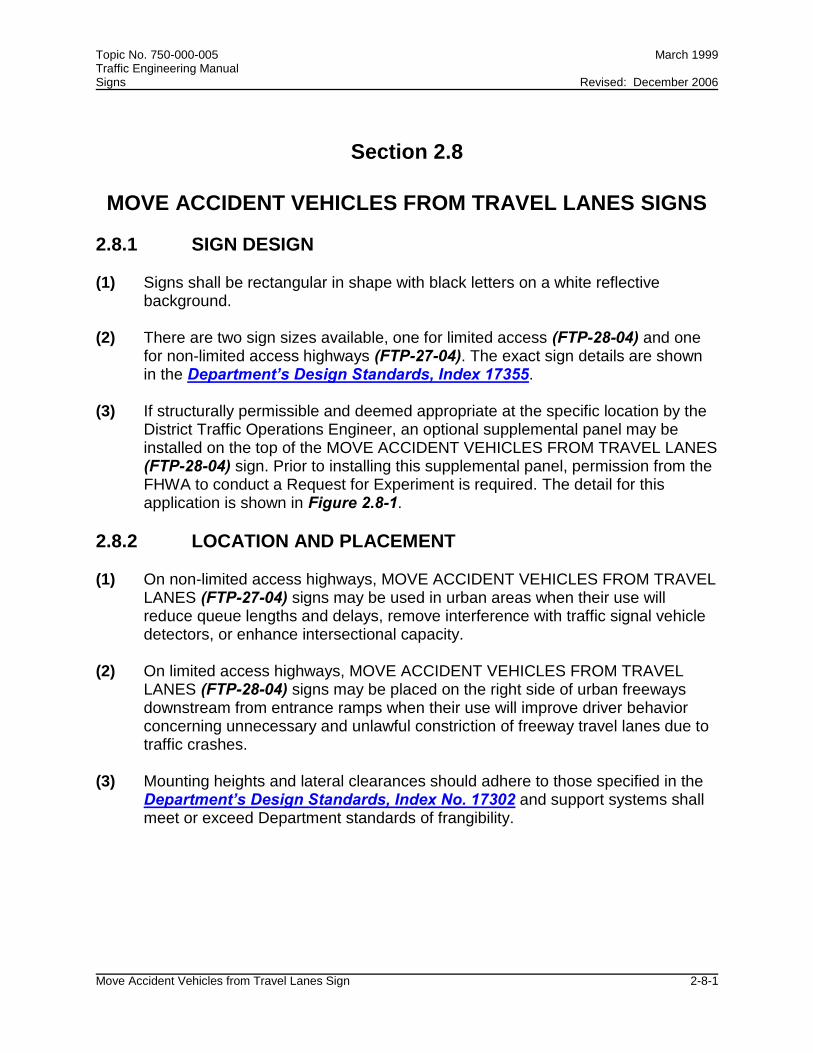
MOVE ACCIDENT VEHICLES FROM TRAVEL LANES SIGNS
2.8.1 SIGN DESIGN (1) Signs shall be rectangular in shape with black letters on a white reflective
background. (2) There are two sign sizes available, one for limited access (FTP-28-04) and one
for non-limited access highways (FTP-27-04). The exact sign details are shown in the Department’s Design Standards, Index 17355.
(3) If structurally permissible and deemed appropriate at the specific location by the
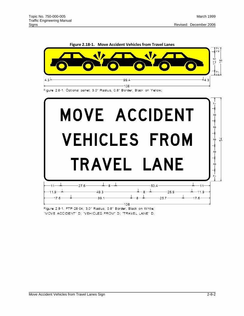
District Traffic Operations Engineer, an optional supplemental panel may be installed on the top of the MOVE ACCIDENT VEHICLES FROM TRAVEL LANES (FTP-28-04) sign. Prior to installing this supplemental panel, permission from the FHWA to conduct a Request for Experiment is required. The detail for this application is shown in Figure 2.8-1.
2.8.2 LOCATION AND PLACEMENT (1) On non-limited access highways, MOVE ACCIDENT VEHICLES FROM TRAVEL
LANES (FTP-27-04) signs may be used in urban areas when their use will reduce queue lengths and delays, remove interference with traffic signal vehicle detectors, or enhance intersectional capacity.
(2) On limited access highways, MOVE ACCIDENT VEHICLES FROM TRAVEL
LANES (FTP-28-04) signs may be placed on the right side of urban freeways downstream from entrance ramps when their use will improve driver behavior concerning unnecessary and unlawful constriction of freeway travel lanes due to traffic crashes.
(3) Mounting heights and lateral clearances should adhere to those specified in the
Department’s Design Standards, Index No. 17302 and support systems shall meet or exceed Department standards of frangibility.
Topic No. 750-000-005 March 1999 Traffic Engineering Manual Signs Revised: December 2006
Move Accident Vehicles from Travel Lanes Sign 2-8-2
Figure 2.18-1. Move Accident Vehicles from Travel Lanes
Topic No. 750-000-005 March 1999 Traffic Engineering Manual Signs
No Passing Zone Signs 2-9-1
Section 2.9
NO PASSING ZONE SIGNS
(1) The NO PASSING ZONE (W14-3) pennant sign shall not be used routinely at the beginning of all no passing zones.
(2) The NO PASSING ZONE pennant sign may be installed as a supplement to
pavement markings that establish a no passing zone under the following circumstances:
(a) At locations where pavement markings indicating no passing zones are
not visible sufficiently in advance to give the driver adequate warning such as on vertical or horizontal curves.
(b) Other locations where such signs are determined desirable for safety as a
result of an engineering study. (3) Proposed use of NO PASSING ZONE pennant signs at locations meeting the
above criteria shall be reviewed and approved by the District Traffic Operations Engineer prior to installation.

Topic No. 750-000-005 March 1999 Traffic Engineering Manual Signs Revised: December 2006
Vending Machine Signs 2-10-1
Section 2.10
VENDING MACHINE SIGNS
2.10.1 PHYSICAL CHARACTERISTICS
(1) The VENDING MACHINES sign shall be 66 x 30 inches with two lines of legend in 8-inch Series D letters. The legend and border shall be white on blue.
(2) Electronic sign details are available in the Department's Sign Library at the
following website: http://www.dot.state.fl.us/TrafficOperations//Operations/SignLibrary/Motori
st_Srvc/Motorist_Service.shtm
2.10.2 LOCATION AND PLACEMENT
(1) VENDING MACHINES signs will be appended at the bottom and between the supports of REST AREA 1 MILE (D5-1) signs. Such placement will not impair the breakaway characteristics of the sign.
(2) At some rest areas there is a fold-up SAFETY BREAK FREE COFFEE sign in
this location. At these rest areas the VENDING MACHINE sign is to be a fold-up sign also. The 66 x 30-inch size will match the old sign in size.
(3) Normally, the VENDING MACHINES signs will be displayed. However, when the
safety break is in effect, the sign is to be folded to read SAFETY BREAK FREE COFFEE.
(4) The SAFETY BREAK FREE COFFEE sign detail is available in the Department's
Sign Library at the following website: http://www.dot.state.fl.us/TrafficOperations//Operations/SignLibrary/Motori
st_Srvc/Motorist_Service.shtm

Topic No. 750-000-005 March 1999 Traffic Engineering Manual Signs Revised: December 2006
Guidelines for Bicycle Warning Signs 2-11-1
Section 2.11
GUIDELINES FOR BICYCLE WARNING SIGNS
2.11.1 DEFINITIONS
Bicycle Facilities. A general term denoting improvements and provisions by public agencies, to accommodate or encourage bicycling. Designated Bicycle Facilities. Bicycle lanes that are always designated or marked with a solid white line, bike lane signs, and bicycle symbols on the pavement. Designated Bicycle Trails. Any mapped recreational bicycle route. Share the Road Signs. Signs used to warn motorists that bicycles and vehicles can legally use/share travel lanes.
2.11.2 GENERAL INSTRUCTIONS
(1) To have maximum effect, these signs are to be used with discretion only at locations that have a problem and only where one or more of the following criteria are met:
(a) Safety problems when the roadway cannot be improved for bicycle
features. (b) Where there is high bicycle volume. (c) Where there is a conflict or obvious courtesy problem between car and
bicycle sharing the road. (2) Designated bicycling facilities are not eligible for this sign. As a general rule,
corridors where paved shoulders or designated bicycle lanes are present will not be considered unless a special safety or road courtesy problem exists. Then the signs may be placed for added information.
(3) Prior to approval by the District Traffic Operations Engineer, the District Bicycle
Coordinator shall review volumes and crash data and provide recommendations for all signing requests.

Topic No. 750-000-005 March 1999 Traffic Engineering Manual Signs Revised: December 2006
Guidelines for Bicycle Warning Signs 2-11-2
2.11.3 WHEN SIGN REQUESTS MAY BE APPROVED
(1) Roadway sections with a significant history of bicycle crashes will be considered for signing.
(2) Roadway sections where motorists are likely to pass one or more bicyclists at
least every one to three miles during daylight hours should be considered for signing.
(3) Roadway sections that have special problems should be considered even if a
lower volume of bicycling is anticipated. For instance, a roadway section that has the potential to attract bicyclists that has been narrowed from the standard 12-foot width may be considered.
(4) Where designated bicycle trails are placed on short stretches of a major roadway
that has not been improved for bicycling. (5) On approaches to bridges or any other section where motorists and bicyclists
have reduced sight distance, operating widths or have been compromised due to right of way or actual roadway geometry restrictions.
(6) Roadway sections adjacent to shared use paths where for the safety of other
path users (pedestrians, children) and the cyclists' own safety, SHARE THE ROAD signing may be considered.
2.11.4 SIGN DESIGN (1) The SHARE THE ROAD Sign is a combination of the federally approved
BICYCLE CROSSING WARNING SIGN (W11-1) and the SHARE THE ROAD (W16-1) plaque. The use of the W11-1 sign is shown in Section 9B.17 of the MUTCD. The use of the W16-1 supplemental plaque is shown in Section 9B.18 of the MUTCD.
(2) The W11-1 sign is 30 x 30 inches and yellow and black in color. The W16-1 sign
is a 18 x 24-inch supplemental plaque, with 4-inch Series C lettering, yellow and black in color. These signs can also be used in fluorescent yellow-green and black if it satisfies the criteria shown in Section 2.29.2.2 of the TEM. However, it is important that both sign panels be the same color.
(3) An example of the SHARE THE ROAD sign is shown in Figure 2.11-1.

Topic No. 750-000-005 March 1999 Traffic Engineering Manual Signs Revised: December 2006
Guidelines for Bicycle Warning Signs 2-11-3
2.11.5 SIGN PLACEMENT
(1) The SHARE THE ROAD signs should be installed according to Section 9B.18 of the MUTCD.
(2) The signs shall be mounted according to height and lateral clearances specified
in the Department's Design Standards, Index No. 17302. (3) The sign shall be installed only at locations reviewed and approved by the District
Traffic Operations Engineer to ensure that such signs do not interfere with existing traffic control devices.
(4) Where a bike lane ends the SHARE THE ROAD sign (Figure 2.11-1) may be
used instead of the BIKE LANE ENDS sign (R3-16a).
Figure 2.11-1. Share the Road Sign

Topic No. 750-000-005 March 1999 Traffic Engineering Manual Signs Revised: December 2006
Recycling Collection Center Signs 2-12-1
Section 2.12
RECYCLING COLLECTION CENTER SIGNS
2.12.1 DEFINITION
Recycling Collection Center. A facility open full time to the general public for the purpose of collecting items to be recycled, e.g., oil, aluminum, batteries, etc. The facility may operate as part of a recycling plant or may be a collection center for the distribution of these items to a recycling center elsewhere.
2.12.2 SIGN DESIGN
(1) The RECYCLING COLLECTION CENTER (FTP-48-04) sign shall be 42 x 60 inches. Lettering shall be 4-inch, Series C. The legend and border shall be white on green.
(2) The RECYCLING COLLECTION CENTER W/OPTIONAL MUNICIPALITY NAME
(FTP-49-04) sign shall be 42 x 66 inches. Lettering shall be 4-inch, Series C. The legend and border shall be white on green.
(3) A Directional Arrow (M-Series) may be attached below the sign panel if desired. (4) Exact sign details for both the FTP-48-04 and the FTP-49-04 can be found in the
Department's Sign Library at the following website: http://www.dot.state.fl.us/TrafficOperations//Operations/SignLibrary/Guide/Guide.shtm
2.12.3 SIGN INSTALLATION
(1) Sign requests must be submitted by local government to the appropriate District Traffic Operations Office for review and approval.
(2) RECYCLING COLLECTION CENTER signs placed on the State Highway
System should adhere to the mounting heights and lateral clearances specified in the Department’s Design Standards, Index Number 17302. Support systems shall meet or exceed the standards shown in Section 700-2.3 of the Department's Standard Specifications.
(3) RECYCLING COLLECTION CENTER signs shall not be permitted in a location
where the view of existing traffic control devices may be obscured or where they might otherwise compete for the motorist's attention, for example, next to a stop sign.

Topic No. 750-000-005 March 1999 Traffic Engineering Manual Signs Revised: December 2006
Signing for Safety Belt Use and 2-13-1 Child Restraint Laws
Section 2.13
SIGNING FOR SAFETY BELT USE AND CHILD RESTRAINT LAWS
2.13.1 PURPOSE To help reduce the number of highway deaths and injuries; to encourage compliance of motorists with the state’s safety belt use and child restraint laws; and to establish uniform criteria for district implementation of signing for safety belt use and child restraint laws.
2.13.2 BACKGROUND
The Florida Safety Belt Law (Section 316.614, F.S.), mandates state agencies conduct a continuing safety and public awareness campaign and adopt programs designed to encourage compliance with usage requirements of the safety belt law. It is the intent of this procedure to support the actions of this statute and provide appropriate signing.
2.13.3 STATE HIGHWAY SYSTEM POINTS OF ENTRY
(1) Districts Two and Three shall install and maintain signing at all State Highway System points of entry, informing motorists of the statutory requirement for safety belt use in the State of Florida.
(2) On limited access highways, a FLORIDA SEATBELT AND CHILD RESTRAINT
LAW sign (FTP-44-04) shall be installed downstream of existing “Welcome to Florida” and speed limit signs.
(3) On non-limited access highways, a FLORIDA SEATBELT AND CHILD
RESTRAINT LAW sign (FTP-45-04) shall be installed downstream of existing "Welcome to Florida" and speed limit signs.
2.13.4 REST AREAS AND INTERSTATE WELCOME CENTERS
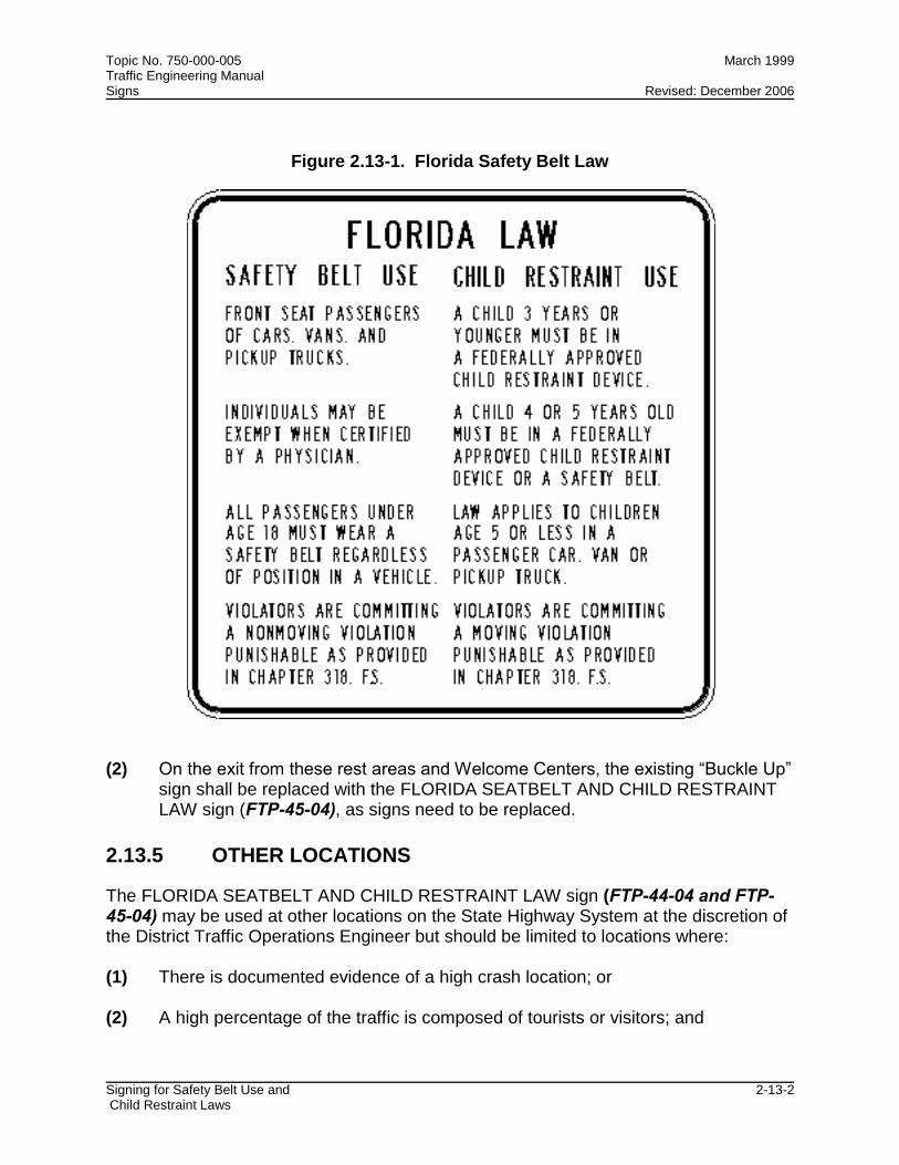
(1) A Rest Area Seatbelt Law sign (Figure 2.13-1) shall be installed and maintained in all rest areas and Interstate Welcome Centers informing motorists of the specific requirements of Florida’s safety belt and child restraint laws. This sign shall be placed in a prominent location for easy viewing by pedestrians using the facilities.
Topic No. 750-000-005 March 1999 Traffic Engineering Manual Signs Revised: December 2006
Signing for Safety Belt Use and 2-13-2 Child Restraint Laws
Figure 2.13-1. Florida Safety Belt Law
(2) On the exit from these rest areas and Welcome Centers, the existing “Buckle Up”
sign shall be replaced with the FLORIDA SEATBELT AND CHILD RESTRAINT LAW sign (FTP-45-04), as signs need to be replaced.
2.13.5 OTHER LOCATIONS
The FLORIDA SEATBELT AND CHILD RESTRAINT LAW sign (FTP-44-04 and FTP-45-04) may be used at other locations on the State Highway System at the discretion of the District Traffic Operations Engineer but should be limited to locations where: (1) There is documented evidence of a high crash location; or (2) A high percentage of the traffic is composed of tourists or visitors; and

Topic No. 750-000-005 March 1999 Traffic Engineering Manual Signs Revised: December 2006
Signing for Safety Belt Use and 2-13-3 Child Restraint Laws
(3) The sign will not interfere or detract from existing regulatory, guide, or warning signs or other traffic control devices.
2.13.6 STANDARD SAFETY BELT SIGN (FTP-46-04 AND FTP-47-04)
(1) This sign is to be used for general education purposes. (2) The 36 x 48 inch sign (FTP-46-04) should be installed on limited access facilities
at county lines, based on space available. The District Traffic Operations Engineers may also install this sign where there is a documented need.
(3) The 24 x 30 inch sign (FTP-47-04) is to be installed on non-limited access
highways and urban areas, based on space available and where there is a documented need.
2.13.7 SIGN DESIGN (1) Specific sign details for all signs referenced in this section are shown in the
Department's Design Standards, Index Number 17355. (2) Electronic details for all the signs in this section are available from the
Department's Sign Library at the following website: http://www.dot.state.fl.us/TrafficOperations/Operations/SignLibrary/Regulatory/Regulatory.shtm
2.13.8 SIGN AVAILABILITY
Maintenance may obtain new or replacement signs by requisition from the Lake City Sign Shop.
Topic No. 750-000-005 March 1999 Traffic Engineering Manual Signs Revised: December 2006
Signing for Evacuation Routes 2-14-1
Section 2.14
SIGNING FOR EVACUATION ROUTES
2.14.1 PURPOSE
To establish a uniform basis for installing and maintaining evacuation route signs on the State Highway System.
2.14.2 BACKGROUND
(1) Emergency management officials requested the Department to install and maintain evacuation route signs on those portions of the State Highway System that comprise official evacuation routes to educate motorists as to the available routes and to ensure that signs are in place well in advance of the actual need to guide motorists away from high risk areas.
(2) The Secretary of Transportation determined that evacuation route signs would be
installed and in place on the State Highway System prior to the hurricane season (June through November). The Department of Community Affairs, Division of Emergency Management, the Department of Law Enforcement, the Florida Highway Patrol, the Department’s State Safety office, and the Florida counties collectively developed statewide regional evacuation plans. Each regional plan includes the Traffic Management Element (routes and manpower), a sheltering element, and the public information element. The regional evacuation plans move evacuees from a high-risk location to a specific safer location (shelter, family residence, etc.).
(3) In the absence of specific sign standards in the MUTCD, the Department with the
guidance and concurrence of the Federal Highway Administration (FHWA) determined that use of Modified CD-1 Evacuation Signs, removing the CD symbol and arrow and adding the weather symbol for a hurricane, was appropriate.
2.14.3 PROCEDURE
(1) The State Traffic Operations Engineer will obtain a hurricane regional evacuations plan showing the approved routes and a listing of County Emergency Management Directors for the Department's Emergency Coordinating Officer, and shall forward them to the appropriate District Traffic Operations Engineer.
(2) The District Traffic Operations Engineer shall initiate the actions necessary at the
district level to implement these guidelines and that evacuation routes are

Topic No. 750-000-005 March 1999 Traffic Engineering Manual Signs Revised: December 2006
Signing for Evacuation Routes 2-14-2
properly and promptly signed. District Maintenance will ensure that the signs are installed and maintained in the field.
(3) The District Traffic Operations Engineer shall contact the County Emergency
Management Director and coordinate state signing efforts through the Emergency Management Director with the appropriate local governments.
(4) Subsequent signing changes necessitated by Department of Community Affairs,
Division of Emergency Management approved changes in evacuation routes shall be handled by the District Traffic Operations Engineer upon request of the regional counties coordinated through the Department's Emergency Coordination Officer.
(5) Technical questions regarding evacuation routes may be directed to the
Department's Emergency Coordinating Officer (State Safety office).
2.14.4 SIGN DESIGN
(1) The EVACUATION ROUTE sign shall conform to the Department’s Design Standards, Index No. 17355.
(2) A 24-inch diameter sign (FTP-79-06) may be used by local governments to
indicate roads or streets under local jurisdiction as official evacuation routes. (3) The 24-inch diameter sign (FTP-79-06) shall be used by the Department to
indicate roads on the State Highway System as official evacuation routes. A 36-inch diameter sign (FTP-78-06) shall be used on limited access highways.
(4) Electronic sign details are available at the Department’s Sign Library at the
following website: http://www.dot.state.fl.us/TrafficOperations/Operations/SignLibrary/Motoris
t_Srvc/Motorist_Service.shtm 2.14.5 SIGN USE
(1) The EVACUATION ROUTE sign shall be used exclusively to sign along regional evacuation routes that have been so designated on the approved statewide regional evacuation route plans recorded by the Department of Community Affairs, Division of Emergency Management.
(2) The EVACUATION ROUTE sign shall be used to guide motorists along the
regional evacuation routes to shelter destinations away from potential high-risk areas; i.e., signs shall be posted to guide traffic along the approved routes.
(3) The sign shall comply with applicable provisions of the MUTCD.

Topic No. 750-000-005 March 1999 Traffic Engineering Manual Signs Revised: December 2006
Signing for Evacuation Routes 2-14-3
2.14.6 SIGN PLACEMENT
(1) Signs shall be placed in accordance with existing Department standards and be consistent with the MUTCD and safety criteria.
(2) The EVACUATION ROUTE sign shall be erected 150 to 300 feet in advance of,
and at any turn in an approved evacuation route and elsewhere for straight-ahead confirmation, if needed. The signs shall be mounted according to height and lateral clearances specified in the Department's Design Standards Index No. 17302.
2.14.7 SIGN INSTALLATION
(1) Signs shall be furnished, installed, and maintained by the Department on official evacuation routes that are on the State Highway System.
(2) Signs shall be installed only at locations reviewed and approved by the District
Traffic Operations Engineer to insure that such signs do not interfere with existing traffic control devices.
2.14.8 SHELTER AND TRAVELER INFORMATION SIGNING
(1) The statewide emergency evacuation plan must compliment both local and regional evacuation plans. In order to assist in this effort, shelter signing and emergency evacuation traveler information is included in this section.
(2) The State Traffic Operations Engineer will coordinate, address, and implement
operational concerns on evacuation route signing and related operational needs with the Safety office and other offices within the Department and with the Department of Community Affairs, Division of Emergency Management.
(3) The District Traffic Operations Engineers will coordinate evacuation shelter
signing efforts on a districtwide basis. If signing for shelters or evacuation traveler information is required, the use of the signs must be included in the CEMP (Comprehensive Emergency Management Plan) area/regional evacuation plan. The plan should assign responsibility for turning the “flip up” signs up during emergency conditions, and back down when conditions return to normal.
(4) Shelter signing will be installed on limited access highways at key locations. The
location determination shall be a joint effort between the District Traffic Operations Engineer and the local agencies.

Topic No. 750-000-005 March 1999 Traffic Engineering Manual Signs Revised: December 2006
Signing for Evacuation Routes 2-14-4
(5) Signs will be installed under the following conditions: (a) the shelter location is part of the regional plan; (b) the local agency shall purchase the signs; (c) the local agency shall be responsible to "flip-up" or "flip-down" the signs
pursuant to their needs.
2.14.9 SHELTER SIGN DESIGN AND USE
(1) The color for shelter signs will be blue background with white legend and directional arrow.
(2) The type of shelter signing support used on the State Highway System, portable
(temporary), or permanent, will be determined by the District Traffic Operations Engineer.
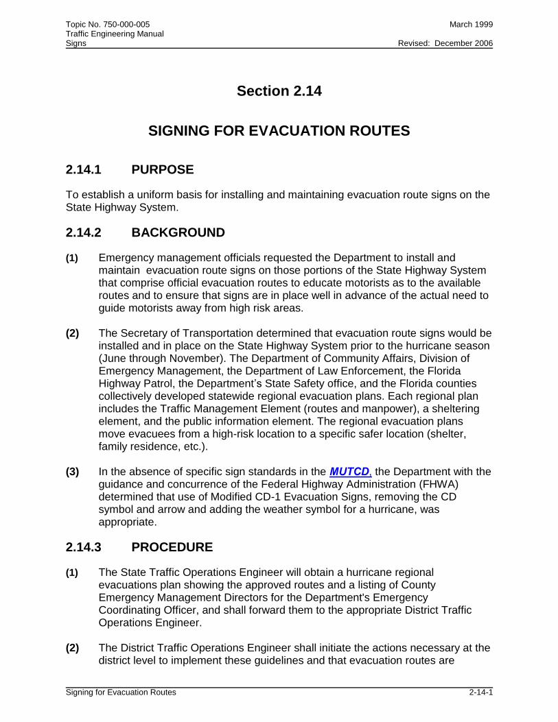
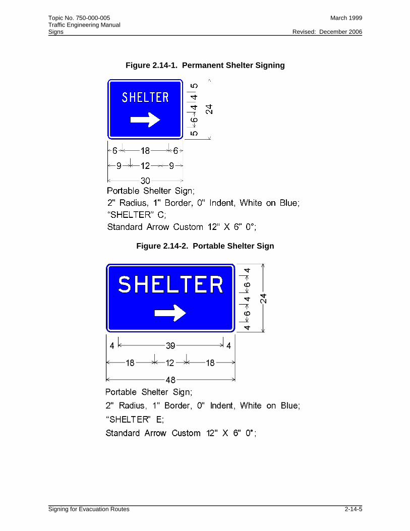
(3) The sign designs for shelters are shown in Figure 2.14-1 for permanent signing
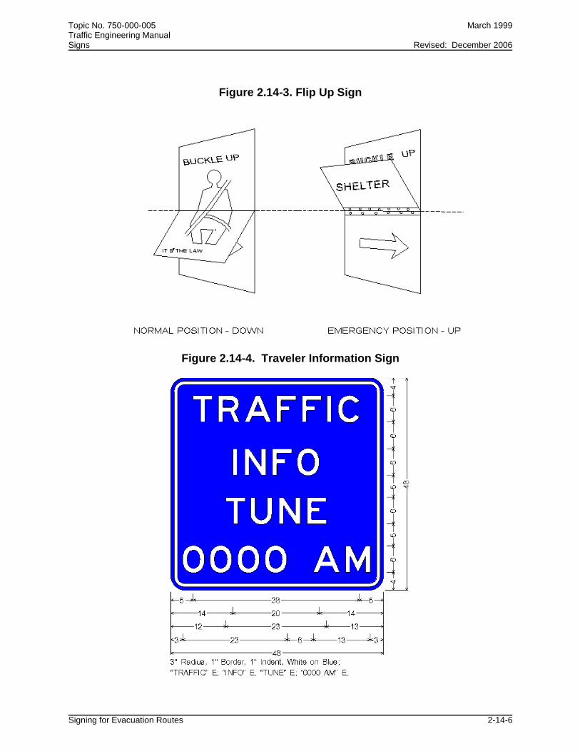
and Figure 2.14-2 for temporary. The permanent design will use a “flip up” design as shown in Figure 2.14-3. This means the bottom panel will be flipped up to reveal the shelter message. The Safety Belt Symbol Sign shall be used as the default message for shelter signs.
2.14.10 TRAVELER INFORMATION SIGNING DESIGN AND USE
(1) The Traveler Information sign shall have a blue background with a white legend. The exact sign detail is shown in Figure 2.14-4.
(2) When the local/regional CEMP plan includes the use of traveler information on
local shelters and other evacuation information, and a local radio station has a written agreement to be the official traveler information station, the frequency of the station may be signed for on the interstate system. This can be done with Changeable Message Signs, or with permanent flip up signs as shown in Figure 2.14-3. A default message for the "flip up" sign shall be the Safety Belt Symbol sign.
Topic No. 750-000-005 March 1999 Traffic Engineering Manual Signs Revised: December 2006
Signing for Evacuation Routes 2-14-5
Figure 2.14-1. Permanent Shelter Signing
Figure 2.14-2. Portable Shelter Sign
Topic No. 750-000-005 March 1999 Traffic Engineering Manual Signs Revised: December 2006
Signing for Evacuation Routes 2-14-6
Figure 2.14-3. Flip Up Sign
Figure 2.14-4. Traveler Information Sign
Topic No. 750-000-005 March 1999 Traffic Engineering Manual Signs Revised: December 2006
Signing for Evacuation Routes 2-14-7
2.14.11 CONTINUOUS HINGE REQUIREMENTS
The continuous hinge shall be of stainless steel, with minimum .060-inch leaf thickness, 2-inch open width and .120 pin diameter. The hinge shall be attached to the aluminum sign panels with 1/8-inch stainless steel pop rivets installed on 4-inch centers for the width of the sign. The pin must be permanently located in place by shortening the pin at each end of the hinge and staking the ends of the two outboard knuckles. Two sources for these hinges are: H.A. Guden Co. (800) 344-6437 FAX (516) 737-2933 Stanley Co. (800) 622-4393 FAX (800) 445-5723
2.14.12 RADIO FREQUENCY INFORMATION SIGNS The addition of radio frequency information signs along evacuation routes on the State Highway System has been approved by the Department as an important communication link for public safety during evacuation periods. The addition of these signs was made possible when Florida Public Radio Stations volunteered to partner with other state and local agencies in the state's evacuation efforts.
2.14.12.1 Radio Frequency Information Sign Design The electronic sign details for the radio frequency signs (for both limited and non-limited access highways) are available in the Department’s Sign Library at the following website: http://www.dot.state.fl.us/TrafficOperations/Operations/SignLibrary/Motorist_Srvc/Motorist_Service.shtm 2.14.12.2 Radio Frequency Information Sign Placement (1) The Radio Frequency Information Sign (Figure 2.14-5) will be placed at the
following locations: (a) All limited access highways classified as evacuation routes. (b) Principal non-limited access highways in areas where limited access
highways are not the main evacuation routes. (c) Principal non-limited access highways that are critical links leading to
limited access highways.

Topic No. 750-000-005 March 1999 Traffic Engineering Manual Signs Revised: December 2006
Signing for Evacuation Routes 2-14-8
(2) Limited access highways will consist of a FTP-78-06 sign and a 36 x 24-inch Radio Frequency Information sign (FTP-71-06). Exact sign details can be found in the Department’s Design Standards, Index 17355.
(3) This sign assembly will be positioned near county lines (where radio coverage is
present) and where radio frequency coverage change. When overlap occurs, the frequency motorists would be driving into is the correct frequency to sign.
Figure 2.14-5. Radio Frequency Information Sign
(4) Evacuation routes on the State Highway System non-limited access highways
are signed with the FTP-79-06 sign. A 24 x 18-inch Radio Frequency Information sign (Figure 2.14-5) will be attached to the existing sign assembly in the above mentioned locations erected close to the county lines or coverage area changes are to be modified with the addition of the radio frequency panel. Additional locations to be modified are the beginning and termination points of qualifying links.
(5) Electronic details for these signs can be found in the Department’s Sign Library
at the following website: http://www.dot.state.fl.us/TrafficOperations/Operations/SignLibrary/Motoris
t_Srvc/Motorist_Service.shtm (6) When long segments occur on both limited access and non-limited access
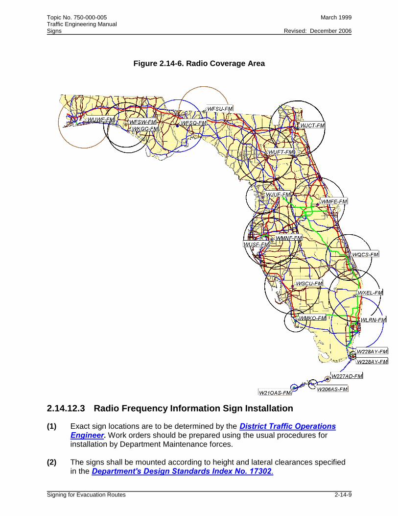
highways, confirmation signs should be installed at 10-mile increments. (7) Figure 2.14-6 represents the general statewide radio coverage area for this
program.
Topic No. 750-000-005 March 1999 Traffic Engineering Manual Signs Revised: December 2006
Signing for Evacuation Routes 2-14-9
Figure 2.14-6. Radio Coverage Area
2.14.12.3 Radio Frequency Information Sign Installation
(1) Exact sign locations are to be determined by the District Traffic Operations Engineer. Work orders should be prepared using the usual procedures for installation by Department Maintenance forces.
(2) The signs shall be mounted according to height and lateral clearances specified
in the Department's Design Standards Index No. 17302.
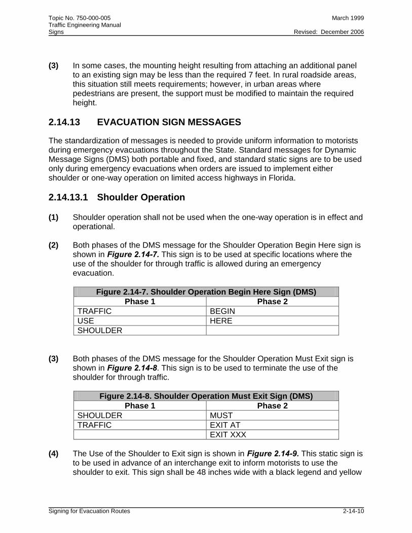
Topic No. 750-000-005 March 1999 Traffic Engineering Manual Signs Revised: December 2006
Signing for Evacuation Routes 2-14-10
(3) In some cases, the mounting height resulting from attaching an additional panel to an existing sign may be less than the required 7 feet. In rural roadside areas, this situation still meets requirements; however, in urban areas where pedestrians are present, the support must be modified to maintain the required height.
2.14.13 EVACUATION SIGN MESSAGES
The standardization of messages is needed to provide uniform information to motorists during emergency evacuations throughout the State. Standard messages for Dynamic Message Signs (DMS) both portable and fixed, and standard static signs are to be used only during emergency evacuations when orders are issued to implement either shoulder or one-way operation on limited access highways in Florida.
2.14.13.1 Shoulder Operation (1) Shoulder operation shall not be used when the one-way operation is in effect and
operational. (2) Both phases of the DMS message for the Shoulder Operation Begin Here sign is
shown in Figure 2.14-7. This sign is to be used at specific locations where the use of the shoulder for through traffic is allowed during an emergency evacuation.
Figure 2.14-7. Shoulder Operation Begin Here Sign (DMS)
Phase 1 Phase 2
TRAFFIC BEGIN
USE HERE
SHOULDER
(3) Both phases of the DMS message for the Shoulder Operation Must Exit sign is
shown in Figure 2.14-8. This sign is to be used to terminate the use of the shoulder for through traffic.
Figure 2.14-8. Shoulder Operation Must Exit Sign (DMS)
Phase 1 Phase 2
SHOULDER MUST
TRAFFIC EXIT AT
EXIT XXX
(4) The Use of the Shoulder to Exit sign is shown in Figure 2.14-9. This static sign is
to be used in advance of an interchange exit to inform motorists to use the shoulder to exit. This sign shall be 48 inches wide with a black legend and yellow

Topic No. 750-000-005 March 1999 Traffic Engineering Manual Signs Revised: December 2006
Signing for Evacuation Routes 2-14-11
background. The sign shall be located on the right shoulder in advance of the exit ramp in accordance with the emergency evacuation implementation plans.
Figure 2.14-9. Use Shoulder to Exit Sign (Static)
(5) The Traffic Using Shoulder sign is shown in Figure 2.14-10. This static sign shall
be used on the entrance ramp to WARN motorist that the limited access highway shoulder is being used for through traffic. The sign is to be located on both the right and left side of the roadway near the beginning of the entrance ramp. This sign shall be 48 inches wide with a black legend and yellow background.
(6) The No Merge Lane Ahead sign shown in Figure 2.14-11.. This static sign shall
be used to warn motorists that there is no room to merge onto the limited access highway. This sign shall be 48 inches wide with a black legend and yellow background. The sign is to be located on both the right and left sides of the ramp, before the entrance ramp gore.

Topic No. 750-000-005 March 1999 Traffic Engineering Manual Signs Revised: December 2006
Signing for Evacuation Routes 2-14-12
Figure 2.14-10. Traffic Using Shoulder Sign (Static)
2.14.13.2 Dynamic Message Signs (DMS)
(1) The flashing of any DMS legend is prohibited. There shall not be more than two phases displayed on any DMS.
(2) All DMS signs used (both portable and permanent) shall be on the Department's
Approved Product List.

Topic No. 750-000-005 March 1999 Traffic Engineering Manual Signs Revised: December 2006
Signing for Evacuation Routes 2-14-13
Figure 2.14-11. No Merge Lane Ahead Sign (Static)
2.14.13.3 Location of DMS and Static Signs
(1) The exact location of the DMS and static signs will be determined as part of the emergency evacuation implementation plans for limited access highways that are developed in each District.
(2) Static signs shall be mounted according to height and lateral clearances
specified in the Department's Design Standards Index No. 17302.
Topic No. 750-000-005 March 1999 Traffic Engineering Manual Signs Revised: December 2006
Smoke on the Highway Signs 2-15-1
Section 2.15
SMOKE ON HIGHWAY SIGNS
2.15.1 GENERAL
(1) The occurrence of fires in proximity to highways in Florida often creates safety hazards to motorists. These fires can be wildfires or controlled burns under prescribed conditions. In virtually every case, Florida Department of Agriculture and Consumer Services, Division of Forestry (DOF) officials are most knowledgeable about the location and seriousness of the situation.
(2) A Highway Safety Smoke Management Interagency Agreement has been
developed between DOF, FDOT and the Florida Highway Patrol (FHP) to provide a cooperative effort to warn the public about roadway visibility hazards resulting from wildfires and prescribed burns.
(3) Several years ago portable temporary smoke warning signs were provided by the
FDOT for use by DOF officials. These signs are to be used in emergency situations where smoke creates a hazard to motorists. This section of the Traffic Engineering Manual describes this practice and documents the authority of the DOF to erect temporary signs when there is smoke present from either wildfires or prescribed burns on the State Highway System.
2.15.2 TEMPORARY SMOKE ON THE HIGHWAY SIGN
(1) Each Forest Area Supervisor employed by the DOF is authorized to approve the placement of portable sign assemblies warning motorists of smoke on the State Highway System. These signs should be erected when there is sufficient smoke present to create a safety concern to motorists.
(2) The signs and support hardware must comply with Department standards and
shall consist of a portable wind resistant stand and roll-up 48-inch non-reflective sign with Series C Lettering. The electronic sign detail is available in the Department’s Sign Library at the following website:
http://www.dot.state.fl.us/TrafficOperations/Operations/SignLibrary/Warnin
g/Warning.shtm

Topic No. 750-000-005 March 1999 Traffic Engineering Manual Signs Revised: December 2006
Smoke on the Highway Signs 2-15-2
2.15.3 PRESCRIBED BURN SIGN
(1) Retro-reflective, non-temporary signs are to be used for prescribed burns. These are burns that are pre-planned and approved through the DOF authorization process. The signs will be supplied, erected, and removed by the person planning and executing the burn.
(2) The person(s) planning and executing the prescribed burn shall provide a decal
on the back of the sign which has both the contact information and the date the sign was placed on the State Highway System.
(3) Person(s) planning and executing a prescribed burn will contact the applicable
FDOT Maintenance yard to notify them that signs are being placed on the State Highway System roadways in anticipation of a burn. The information given to the maintenance yard shall include the exact time and location of the signs and contact information for the persons conducting the burn.
(4) It is the responsibility of the person planning and executing the prescribed burn to
contact Call Sunshine (1-800-432-4770) 48 hours prior to installing the signs to insure no conflict with existing utilities.
(5) The sign used for prescribed burns will contain black lettering on a yellow retro-
reflective background with Series C Lettering. Sign materials shall comply with the current edition of the Department's DOT Standard Specifications for Highway and Bridge Construction, Section 994.
(a) The sign size shall be a 36-inch diamond shape when installed on
roadways posted at 50 mph or less.
(b) The sign size shall be a 48-inch diamond shape when installed on roadways posted at 55 mph or greater.
Electronic sign details are available at the Department’s Sign Library at the
following website: http://www.dot.state.fl.us/TrafficOperations/Operations/SignLibrary/Warnin
g/Warning.shtm
(6) Sign sheeting shall be Type IIIA, IIIB, or IIIC, fastened to an aluminum substrate at least 0.080 thick. Signs shall be mounted in accordance with the current edition of the Department's Design Standards, Index No. 600, Sheet 4 of 11 using round aluminum or steel channel as follows:
Aluminum: 3.5" x 3/16"

Topic No. 750-000-005 March 1999 Traffic Engineering Manual Signs Revised: December 2006
Smoke on the Highway Signs 2-15-3
Steel channel: two 3.0# at 2'-6" center to center Using 2-I and 1-II brackets. (7) Mounting heights and lateral clearances should adhere to those specified in the
current edition of the Department's Design Standards, Index No. 17302: Case II (rural locations) Sign edge 12' minimum from driving lane edge Case V (urban locations) Sign edge 2' minimum from face of curb
2.15.4 SIGN INSTALLATION AND REMOVAL
(1) The signs shall be installed 1/2 mile in advance of the hazard area in both directions to allow motorists sufficient time to react to the sign message. Signs shall be double-mounted on divided highways.
(2) The appropriate FHP Troop Headquarters shall be notified within the shortest
possible time, not to exceed one (1) hour, when the appropriate smoke on highway signs are used so that coordinated efforts can be developed.
(3) It is important to note where and when the signs were placed. Due to the fact that
smoke moves, frequent monitoring is needed to assure proper placement. (4) Conditions must be monitored and the signs removed when conditions improve
to the extent where these signs are not needed. The removal of these signs shall be done by DOF personnel or FDOT Maintenance forces, whoever erected the sign, with coordination with the FHP.

Topic No. 750-000-005 March 1999 Traffic Engineering Manual Signs Revised: April 2005
Supplemental Guide Signs and Motorist Services and Limited and Non-limited Highways 2-16-1
Section 2.16
SUPPLEMENTAL GUIDE SIGNS AND MOTORIST SERVICES ON LIMITED AND NON-LIMITED ACCESS HIGHWAYS
This section has been rescinded since it is now adopted as Florida’s Highway Guide Sign Program in Rule Chapter 14-51 and can been accessed at following Web site: http://www.dot.state.fl.us/trafficoperations/Operations/Studies/TEM/14-51.shtm
Topic No. 750-000-005 March 1999 Traffic Engineering Manual Signs Revised: April 2009
Emergency Highway Traffic Plan 2-17-1
Section 2.17
EMERGENCY HIGHWAY TRAFFIC PLAN
This section of the TEM has been rescinded and replaced with the Emergency Management Program (Topic Number 500-000-104) which is sponsored by the State Safety Office.

Topic No. 750-000-005 March 1999 Traffic Engineering Manual Signs Revised: December 2006
*FHP Highway Assistance Program 2-18-1
Section 2.18
*FHP HIGHWAY ASSISTANCE PROGRAM
2.18.1 PURPOSE (1) The *FHP Highway Assistance Program is a statewide program where motorists
wishing to report highway related information to the Florida Highway Patrol can do so by using their cellular phone. Signs will be erected to inform motorists of the cellular phone number.
(2) The signing program will extend to all Interstate, Toll, U.S. Routes, and other
major State Highway System roadways throughout the state.
2.18.2 SIGN LOCATION The location of these signs should correspond to areas where cellular service is available. The service is available in all counties of the state; however, there are areas in some counties which are not covered.
2.18.3 SIGN DESIGN AND INSTALLATION
(1) The *FHP sign (FTP-43-04) is 48 x 48 inches, has a white legend on blue background, and the exact sign detail is shown in the Department's Design Standards, Index No. 17355.
(2) The electronic detail for this sign is available from the Department's Sign Library
at the following website: http://www.dot.state.fl.us/TrafficOperations/Operations/SignLibrary/Motoris
t_Srvc/Motorist_Service.shtm (3) The *FHP sign has been revised to provide motorists the number interpretation of
FHP (347), in order to quicken the calling process. This new sign design will be used on all new projects and as signs need to be replaced.
(4) Mounting heights and lateral clearances should adhere to those specified in the
Department's Design Standards, Index No. 17302 and support systems shall meet or exceed Department standards of frangibility.

Topic No. 750-000-005 March 1999 Traffic Engineering Manual Signs Revised: December 2006
*FHP Highway Assistance Program 2-18-2
(5) Specific sign placement details should be developed by District Traffic Operations Offices using the following guidelines.
2.18.3.1 Interstate and Other Limited Access Routes
(1) At state and county lines (2) At approximately 30 mile intervals (3) Following major freeway to freeway interchanges
2.18.3.2 Major Arterial Routes
(1) At state and county lines (2) At approximately 30 mile intervals (3) Downstream from intersections formed by junctions of U.S./Major State Highway
System roadways
2.18.4 SIGN AVAILABILITY Maintenance may obtain new or replacement signs by requisition from the Lake City Sign Shop.

Topic No. 750-000-005 March 1999 Traffic Engineering Manual Signs Revised: December 2006
Call Box/Mile Marker Signs 2-20-1
Section 2.20
CALL BOX/MILE MARKER SIGNS
2.20.1 PURPOSE To establish a uniform basis for the installation of the combined motorist aid call box sign and mile marker sign on existing call box poles along the State Highway System.
2.20.2 INSTALLATION (1) The sign can be installed on the call box poles anytime the call box and the
existing mile marker overlap or when the call box is within 525 feet of the existing mile marker. The sign will serve as both the call box number and the mile marker. The mile marker number shall be to the whole mile. Once the new signs are installed the corresponding mile marker should then be removed.
(2) For call boxes located farther than 525 feet from a mile marker, the call box sign
shall have only the call box number. The mile marker will remain on its own pole at its existing location.
(3) The combination call box and mile marker sign should be installed on all new call
box projects. For existing call boxes, signs should be replaced in total or as knockdowns occur and a replacement sign is required.
(4) When existing call box signs need to be replaced, it will be Maintenance's
responsibility to install the signs. However, for new construction it will be the Contractor's responsibility to supply and install the signs.
2.20.3 SIGN DESIGN (FTP-63-04 and FTP-64-04) (1) The sign shall be 24 x 36 inches. The top half of the sign shall be blue reflective
background with white lettering and the bottom half of the sign shall be green reflective background with white lettering.
(2) For call boxes located at mile markers (FTP-63-04), the call box and mile will
have 4-inch Series E lettering; the milepost numbers will have 6-inch Series E lettering.
(3) For call boxes located between mile markers (FTP-64-04) all lettering will be 4-
inch Series E.

Topic No. 750-000-005 March 1999 Traffic Engineering Manual Signs Revised: December 2006
Call Box/Mile Marker Signs 2-20-2
(4) Electronic sign details for both designs are available at the Department’s Sign Library at the following website:
http://www.dot.state.fl.us/TrafficOperations/Operations/SignLibrary/Motoris
t_Srvc/Motorist_Service.shtm
Topic No. 750-000-005 March 1999 Traffic Engineering Manual Signs Revised: December 2006
Florida Litter Law Signs 2-21-1
Section 2.21
FLORIDA LITTER LAW SIGNS
2.21.1 PURPOSE
In 1988, the Legislature enacted the Solid Waste Act which provided for a comprehensive solution to Florida's solid waste problems by involving state and local governmental entities and the private sector. Section 55 of the Solid Waste Act provided that there must be a coordinated effort to a cleaner environment through sustained programs of litter prevention. Subsection 5 provided that the Department of Transportation must place signs discouraging litter at all off-ramps on the interstate highway system. 2.21.2 SIGN DESIGN AND PLACEMENT
(1) The FLORIDA LITTER LAW sign is to be installed in compliance with Section 403.413(4), F.S.
(2) The Department shall install the FLORIDA LITTER LAW sign (FTP-41-04) on
interstate off-ramps as required by statute. They should be installed a minimum of 100 feet in advance of the first motorist services sign, or a minimum of 100 feet in advance of directional signs on the off-ramps without motorist service signs.
(3) The off-ramp sign shall be 30 x 36 inches with a white background and black
legend (FTP-41-04). The specific sign detail is shown in the Department's Design Standards, Index 17355.
(4) The Department may also install the FLORIDA LITTER LAW sign (FTP-40-04)
on the interstate where there is excessive littering. This sign shall be 42 x 48 inches with a white background and black legend. The specific sign detail is shown in Department's Design Standards, Index 17355.
(5) Electronic sign details are available at the Department’s Sign Library at the
following website: http://www.dot.state.fl.us/TrafficOperations/Operations/SignLibrary/Regulatory/Regulatory.shtm

Topic No. 750-000-005 March 1999 Traffic Engineering Manual Signs Revised: December 2006
Florida Litter Law Signs 2-21-2
2.21.3 SIGN INSTALLATION
(1) Installation of these signs should be completed through the normal methods of locating the sign positions and notifying District Maintenance. Maintenance will order the signs from the Sign Shop and install them.
(2) The FLORIDA LITTER LAW sign (FTP-41-04) may also be installed on the State
Highway System either by the District Traffic Operations Engineer or by local government through the Department's permit process.
(3) Mounting heights and lateral clearances should adhere to those specified in the
Department’s Design Standards, Index No. 17302 and support systems shall meet or exceed Department standards of frangibility.

Topic No. 750-000-005 March 1999 Traffic Engineering Manual Signs Revised: April 2009
Traffic Control for Toll Collection Facilities 2-22-1
Section 2.22
TRAFFIC CONTROL FOR TOLL COLLECTION FACILITIES The Department's standards for this section are now referenced in the Turnpike Plans Preparation and Practices Handbook (TPPPH). The TPPPH can be accessed at the following Web site:
http://design.floridasturnpike.com/prod_design/tppph/tppph2009.html
Topic No. 750-000-005 March 1999 Traffic Engineering Manual Signs Revised: December 2006
Florida’s Turnpike and Toll Road Numbering and Signing Program 2-23-1
Section 2.23
FLORIDA’S TURNPIKE AND TOLL ROAD NUMBERING AND SIGNING PROGRAM
2.23.1 PURPOSE
To establish standards for systematic numbering and signing of Florida’s emerging toll road system.
2.23.2 BACKGROUND
(1) Florida’s toll road system was originally made up of a complex network of locally developed expressways and the Florida Turnpike. The toll roads were developed largely through the efforts of local expressway authorities to serve regional transportation needs, seldom extending into adjacent counties. As locally funded and developed projects, the expressway’s authorities developed a sense of community ownership for the toll road and gave it a locally pleasing name. These names have traditionally been used when referring to the roadway even though state road numbers were assigned to each facility.
(2) Section 338.001, F.S. which has created an intrastate highway system, changed
the local flavor of the toll roads. Now considered a major component of the intrastate system, the toll roads perform a necessary function in transporting the motorist through urban areas in the shortest possible time. Consequently, the Turnpike District of the Department is responsible for the administration and expansion of many of the toll roads. Some of these are already open, others are in the planning stages.
(3) As toll roads have expanded and developed over time into a statewide toll
network, a systems approach has been adopted to include connections to other systems. This includes accessibility to local streets, county roads, state system routes, and connections between other limited access systems. An integral part of this interconnected system is the road numbering and signing program.
2.23.3 ROAD NUMBERING PROGRAM
(1) Because of the expanding size of the toll system, the convention of identifying toll roads only by local names is not acceptable. The high number of toll roads and their interconnected nature causes navigation problems for tourists and other non-familiar motorists. A worst case can develop where one expressway joins

Topic No. 750-000-005 March 1999 Traffic Engineering Manual Signs Revised: December 2006
Florida’s Turnpike and Toll Road Numbering and Signing Program 2-23-2
another and the route name suddenly changes without changing roadways. The solution is to use a route numbering system, similar to that used on interstate routes, U.S. routes, and other state highways.
(2) Local names or logos will be retained for identification and a local sense of
ownership only. Local names or logos will continue to be used by resident motorists, but those not familiar with the local system will rely on the numbering system to navigate the statewide system of toll facilities.
(3) The numbering system will be consistent with the statewide numbering systems
for all state and county roads. In most cases the existing state road numbers will be used to refer to the toll roads. For new tollways, a number will be assigned by the Transportation Statistics Office, consistent with the official numbering program. In cases where future facilities will result in the completion of a loop or beltway, connecting a series of shorter toll road segments, a single road number will be retained, often requiring a change of road numbers on older links.
(4) To express membership in the statewide toll system, and provide a consistent
method of identification throughout the State, a sign has been developed (Figure 2.23-1) which depicts the toll road number on a unique sign shape. This sign is similar to an interstate shield and is used as a route marker and as part of the trailblaze assembly.
Figure 2.23-1. Toll Route Marker
2.23.4 SIGNING PROGRAM
(1) The toll route marker (Figure 2.23-1) is available in three sizes, depending on application. To identify the facility along the mainline a 48 x 60-inch toll route
Topic No. 750-000-005 March 1999 Traffic Engineering Manual Signs Revised: December 2006
Florida’s Turnpike and Toll Road Numbering and Signing Program 2-23-3
marker may be used. This sign may be used when leaving the toll plaza to confirm the route and also erected periodically along the mainline.
(2) To maintain the local identity of the toll road, and provide for local area motorists,
the toll road name or logo may be erected on a confirmation guide sign downstream from the mainline toll plazas. If used, the logo panel shall be furnished by the local expressway authority. These local name or logo signs are for identification purposes only. No attempt shall be made to use only the local toll road name or logo in guide signing, direction signing or trailblazing to the facility. A combination of route number signs and expressway names or logos may be necessary to accommodate local concerns, but the principal identification is the toll route marker.
(3) To identify a toll facility at a freeway to freeway interchange, both the advance
guide sign and exit direction guide sign shall use the 36 x 48-inch toll route shield. This size is available as an overlay, and should also be used in other freeway type guide signs and overhead direction sign applications. The local toll road name or 36-inch logo panel may be used in a guide sign or direction sign application. If used, this logo panel shall be furnished by the local expressway authority.
(4) To identify a toll facility from a conventional road, (state, county, or local
systems), or to provide trailblazing to a toll facility a 24 x 30-inch toll route marker shield shall be used in conjunction with the appropriate cardinal direction information, arrows, junctions, etc. The local toll road name or a 24-inch logo panel may be used in conjunction with the toll route marker. If used, this logo panel shall be furnished by the local expressway authority. Confirmation assemblies should be used in trailblazing beyond intersections of numbered routes.
(5) Electronic sign details for these signs can be found at the Department’s Sign
Library at the following website: http://www.dot.state.fl.us/TrafficOperations/Operations/SignLibrary/Guide/
Guide.shtm (6) Although trailblazing to toll facilities is an effective method of advertising for the
facility, the intent of signing is to guide the motorist. The MUTCD is very specific on this issue. General limits on the maximum distance from a toll facility to parallel routes are recommended for rural and urban density development as follows.

Topic No. 750-000-005 March 1999 Traffic Engineering Manual Signs Revised: December 2006
Florida’s Turnpike and Toll Road Numbering and Signing Program 2-23-4
2.23.5 RECOMMENDED MAXIMUM TRAILBLAZE DISTANCE
Rural density 5 miles Urban density 2 miles
Due to the cost of signing and the possibility of overloading the motorist with information, the engineer must use care in locating these signs. Acceptable locations are along major parallel routes, and at the junction of roadways which have exits on the toll road.
2.23.6 LIMITED ACCESS SIGN DESIGNS
(1) For general issues relating to guide signs and the use of regulatory and warning signs, the toll system shall be interpreted as functioning as a fully access controlled roadway with corresponding criteria such as clear zone requirements, letter height, sign placement, etc. (See Section 2E.02 of the MUTCD). The engineer must keep in mind that this level of signing is purposefully kept simple and dignified, using large lettering, and concise messages that can be read, comprehended, and acted upon while traveling at a high rate of speed.
(2) The procedures used for guide sign sequences shall be as for other limited
access facilities. The use of supplemental guide signs for traffic generators shall follow Rule 14-51.020, F.A.C.

Topic No. 750-000-005 March 1999 Traffic Engineering Manual Signs Revised: December 2006
Placement of Crime Watch Signs on the State Highway System 2-24-1
Section 2.24
PLACEMENT OF CRIME WATCH SIGNS ON THE STATE HIGHWAY SYSTEM
2.24.1 PURPOSE
To aid districts in evaluating and responding to requests for erecting Crime Watch Signs within the State Highway System rights-of-way.
2.24.2 DEFINITIONS
Crime Watch Sign. A sign used to identify a neighborhood, community, or other geographical area within which there exists a Crime Watch Program.
2.24.3 BACKGROUND
(1) Crime prevention is an issue of critical concern to both government and its citizens. With the assistance of law enforcement agencies, local citizens have organized Crime Watch Programs to enhance the safety and security of persons and property within their communities. According to law enforcement officials, the erection of Crime Watch Signs indicative of the adoption of a Crime Watch Program can be a deterrent to crime. Generally, local governments erect these signs along residential streets and in business districts.
(2) Crime Watch Signs shall not be considered official traffic control devices and
accordingly are not governed by the MUTCD. However, they do aid in law enforcement and contribute to public safety.
2.24.4 REQUESTS FOR SIGNING
(1) Requests for permitting the erection of Crime Watch Signs within State Highway System rights-of-way should be reviewed by the District Traffic Operations Engineer.
(2) Only requests submitted by local government traffic engineering or law
enforcement agencies should be considered. Others should be referred to their local governmental agencies.

Topic No. 750-000-005 March 1999 Traffic Engineering Manual Signs Revised: December 2006
Placement of Crime Watch Signs on the State Highway System 2-24-2
2.24.5 SIGN LOCATIONS
(1) Crime Watch Signs may be permitted along a State Highway only in the vicinity of strip residential or commercial development which is directly accessed from the State Highway.
(2) Crime Watch Signs should not be permitted on State Highway right-of-way when
the area of concern is adequately served by side streets connecting to the State Highway. In such cases, the signs should be placed on the side street right-of-way and be readily visible to someone entering the side street from the State Highway.
(3) Excessive posting of Crime Watch Signs along a State Highway should not be
permitted. Prudent judgment must be exercised in reviewing signing strategies with respect to the spacing of successive signs. For example, on highways passing through isolated small rural or suburban communities, single signs at the limits of the communities may be appropriate. In heavily developed areas, additional signs at moderate spacing may be needed.
(4) Crime Watch Signs shall not be permitted in a location where the view of existing
traffic control devices may be obscured or where they might otherwise compete for the motorists’ attention (e.g., next to a STOP Sign).
2.24.6 SIGN DESIGN AND PLACEMENT
(1) Since Crime Watch Signs are not official traffic control devices, requests for the Department to design or establish standards for these signs should be declined. However, the District Traffic Operations Engineer should review sign designs proposed for use on the State Highway System. Designs which resemble an official traffic control device or which may be confusing to or misconstrued by the motorists should be rejected.
(2) Sign designs should be simple and dignified, devoid of any advertising. Panel
design and quality should be adequate to maintain a high level of appearance and legibility under anticipated environmental conditions, both day and night.
(3) Mounting heights and lateral clearances should adhere to those specified in the
Department’s Design Standards, Index No. 17302 and support systems shall meet or exceed Department standards of frangibility.
(4) Crime Watch Signs shall not be affixed to any sign support maintained by the
Department.

Topic No. 750-000-005 March 1999 Traffic Engineering Manual Signs Revised: December 2006
Placement of Crime Watch Signs on the State Highway System 2-24-3
2.24.7 INSTALLATION AND MAINTENANCE
(1) A local governmental agency must agree to assume full responsibility for the installation and maintenance of any Crime Watch Signs permitted by the Department for installation on the State Highway System.
(2) The installing agency should be advised that the Department reserves the right to
remove any Crime Watch Signs not in conformance with these instructions or which are not properly installed or maintained.
2.24.8 SPECIAL CONSIDERATIONS
Unusual requests or designs, or problems associated with Crime Watch Signs on the State Highway System should be discussed with the State Traffic Operations Engineer prior to permitting.

Topic No. 750-000-005 September 1999 Traffic Engineering Manual Signs
Distance Signing for Non-limited Access Highways 2-25-1
Section 2.25
DISTANCE SIGNING FOR NON-LIMITED ACCESS HIGHWAYS 2.25.1 PURPOSE To establish a consistent distance signage system for all non-limited access state roads. This section implements Action Plan 006 from the 1994 Evaluation of International Signing Practices Study to establish a statewide destination signing program.
2.25.2 BACKGROUND (1) Section 2D-37 of the MUTCD covers the application of distance signage.
However, there is no statewide procedure for distance signage on non-limited access roads. This perpetuates the situation of signing for a destination on a non-limited access state road that may be several hundred miles away. Also, the current distance signage practice does not take into consideration the use of Interstate and Florida's Turnpike System for long distance driving by motorists.
(2) The Department's current non-limited access distance signs do not provide
adequate destination information for motorists who are looking for the variety of tourist attractions which are accessible from non-limited access highways in addition to destinations accessible from the Interstate and Florida's Turnpike System.
2.25.3 PROCEDURE (1) Distance signs should have the names of three cities, towns, significant
geographical identity, route, or community, and the distance (to the nearest mile) to those places.
(2) The top name should be the next place on the route having a post office, railroad
station, route number (name) of an intersecting highway, or other significant geographical identity.
(3) The middle name should be used to indicate communities along the route or
important route junctions. This name may be varied on successive distance signs to give motorists maximum information concerning communities along the route to the next control city.
(4) The bottom name must a major destination control city. The control city should
remain the same on all successive distance signs throughout the length of the

Topic No. 750-000-005 September 1999 Traffic Engineering Manual Signs
Distance Signing for Non-limited Access Highways 2-25-2
route until that destination qualifies to be the top or middle name on the distance sign. Once the control city moves up, the next control city must be shown as the bottom name. There should always be a control city shown as the bottom name.
(5) Figures 2.25-1, 2.25-2, 2.25-3, and 2.25.4 are examples of distance signs for
non-limited access highways. (6) Placement of distance signs are specified in Section 2D-38 of the MUTCD. (7) Control cities have populations of 10,000 or more and include county seats. A list
of control cities was compiled by the State Traffic Engineering Office and are on file in the respective District Traffic Operations Office.
(8) The implementation of this distance signing program should be through normal
construction projects. The District Traffic Operations Engineer must develop corridor distance signage plans for inclusion into existing work program projects. Stand-alone distance signage projects are not required nor desired.

Topic No. 750-000-005 March 1999 Traffic Engineering Manual Signs Revised: December 2006
Advance Guide Signs on Limited Access Highways 2-26-1
Section 2.26
ADVANCE GUIDE SIGNS ON LIMITED ACCESS HIGHWAYS 2.26.1 PURPOSE To provide uniform statewide advance guide sign applications that ensure motorists are provided advance notification of interchange exits on limited access highways.
2.26.2 BACKGROUND Section 2E.27 of the MUTCD covers the application for interchange guide signs. Action Plan 007 of the 1994 International Signing Practices Study recognized the need of the international tourist for advance notification of exit direction information. The most frequently cited problem of international visitors navigating in Florida was the lack of information about exits. This need is not limited to the international tourist, but to every unfamiliar motorist and also older drivers from both in and out-of-state.
2.26.3 DEFINITIONS
Intermediate Interchange. An interchange with an urban and rural route that is not a major or minor interchange as defined herein (Section 1A.13(38) of the MUTCD). Major Interchange. An interchange with another freeway or expressway, or an interchange with a high-volume multi-lane highway, principal urban arterial, or major rural route where the interchanging traffic is heavy or includes many road users unfamiliar with the area (Section 1A.13(46) of the MUTCD). Minor Interchange. An interchange where traffic is local and very light, such as interchanges with land service access roads. Where the sum of the exit volumes is estimated to be lower than 100 vehicles per day in the design year, the interchange is classified as local (Section 1A.13(49) of the MUTCD). 2.26.4 PROCEDURE (1) For urban areas, two advanced guide signs are required for every major and
intermediate interchange on the Interstate, Florida's Turnpike System, and other limited access roadways.
Topic No. 750-000-005 March 1999 Traffic Engineering Manual Signs Revised: December 2006
Advance Guide Signs on Limited Access Highways 2-26-2
(2) The two advance guide signs should be placed 1/2 mile and 1 mile upstream of the exit. If interchange spacing prohibits the placement of these two advanced guide signs, then the interchange sequential series signs (Sections 2E.27 and 2E.37 of the MUTCD) should be used. Left hand exit interchanges should utilize diagrammatic signs.
(3) For major and intermediate interchanges, the two advance guide signs must be
mounted overhead in urban areas. For rural interchanges either cantilever or ground mounted signs are adequate.
(4) For major interchanges in the rural area and freeway-to-freeway interchanges,
three (3) advance guide signs must be provided and located approximately 1/2 mile, 1 mile, and 2 miles upstream from the exit. For rural intermediate interchanges, two advance guide signs are to be installed.
(5) Implementation of this advance guide sign program should be through
construction projects scheduled in the work program. The District Traffic Operations Engineer must develop a list of interchanges for inclusion into the work program projects. Stand-alone advance guide sign projects are not required to comply with this standard.

Topic No. 750-000-005 March 1999 Traffic Engineering Manual Signs Revised: December 2006
Commuter Assistance Signs 2-27-1
Section 2.27
COMMUTER ASSISTANCE SIGNS 2.27.1 PURPOSE To provide statewide sign design consistency for the Department’s Commuter Assistance Program, Topic Number 725-030-008.
2.27.2 BACKGROUND
Coordinated use of existing transportation resources can provide a responsive, low cost alternative for alleviating urban highway congestion and improving air quality, thereby reducing the need for costly highway improvements. The Commuter Assistance Program focuses on the single occupant commuter trip which is the greatest cause of peak hour highway congestion. A coordinated effort to provide alternatives to these commuters, using existing or low cost resources, can be beneficial to the development of a transportation demand management program and public transit statewide. The State’s Commuter Assistance Program encourages a public/private partnership to provide services to employers and individuals for: carpools, vanpools, express bus service, subscription transit service, group taxi services, heavy and light rail, and other systems which are designed to increase vehicle occupancy.
2.27.3 SIGN DESIGN AND INSTALLATION (1) Section 2E.57 of the MUTCD provides guidance for the installation of a carpool
information sign. The MUTCD states that, "it is in the best interest of the public to permit the use of carpool information signs not only adjacent to preferential lanes but along any urban highway."
(2) Signing requests received from the Department's Public Transit Office or local
transit agencies must be approved by District Traffic Operations Engineers. (3) Sign placement will be determined by District Traffic Operations based on field
review and space availability. (4) The Department's Commuter Assistance Program also includes two additional
modes of services (vanpooling and transit) and there are different signs for each of these services.

Topic No. 750-000-005 March 1999 Traffic Engineering Manual Signs Revised: December 2006
Commuter Assistance Signs 2-27-2
(5) There are two different sizes for each sign design. The arterial sign shall be 36 x 24 inches. The interstate sign shall be 78 x 48 inches. All signs shall be blue reflective background with white lettering.
(6) Exact sign details for the TRY CARPOOLING (FTP-56-04 and FTP-56A-06) TRY
TRANSIT (FTP-59-04 and FTP-60-04) and TRY VANPOOLING (FTP-57-04 and FTP-58-04) are available in the Department’s Design Standards, Index 17355.
(7) Electronic sign details for the all the signs in this section are available in the
Department's Sign Library at the following website: http://www.dot.state.fl.us/TrafficOperations/Operations/SignLibrary/Motoris
t_Srvc/Motorist_Service.shtm (8) Mounting heights and lateral clearances should adhere to those specified in the
Department's Design Standards, Index No. 17302 and support systems shall meet or exceed Department standards of frangibility.

Topic No. 750-000-005 March 1999 Traffic Engineering Manual Signs Revised: December 2006
Mile-Markers on Arterial Highways 2-28-1
Section 2.28
MILE-MARKERS ALONG ARTERIAL ROADWAYS
2.28.1 PURPOSE To establish consistent criteria and signing methods for mile-markers on non-limited access roadways.
2.28.2 STANDARDS
(1) Arterial mile-marker signs shall be as described in Section 2D.46 of the MUTCD. These signs consist of a vertical sign containing the mile-marker number. The sign shall have 6-inch white letters on a green reflective background and be placed on the right side of the roadway at 1-mile or 1/2-mile increments where needed.
(2) The zero distance shall be established at the southern or western state line or at
junctions where the route begins. MUTCD standards shall be followed for overlap routes.
2.28.3 CRITERIA FOR ROUTE SELECTION
(1) While arterial mile-markers will be helpful on many roadways, those with existing positioning systems, i.e., good building numbers, adequate landmarks, and signed cross streets will not benefit significantly. In addition, there may be many requests from municipalities to provide these signs on qualifying roadways. The following criteria shall be used when selecting roadways to use arterial mile-markers:
(a) Cross at least two municipalities or two county jurisdictions within three miles. (b) Relatively devoid of named landmarks, cross streets, or building
addresses that would serve as navigation aids for motorists in the area. (c) Can be identified by local Emergency Medical Services (911) program to assist in address location. (d) The proposed arterial mile-markers should not interfere in any manner with other traffic control devices.

Topic No. 750-000-005 March 1999 Traffic Engineering Manual Signs Revised: December 2006
Mile-Markers on Arterial Highways 2-28-2
(2) Requests for the arterial mile-marker signing must be initiated by local jurisdictions. In all cases, requests shall be directed to the District Traffic Operations Engineer and must meet all the criteria listed above.
(3) The local jurisdiction must, through the permit process, erect and maintain
arterial mile-marker signs on state system roadways, but the District Traffic Operations Engineer is responsible for the route signing plan.

Topic No. 750-000-005 March 1999 Traffic Engineering Manual Signs Revised: December 2006
Use of Fluorescent Yellow-Green Sign Sheeting 2-29-1
Section 2.29
USE OF FLUORESCENT YELLOW-GREEN SIGN SHEETING
2.29.1 PURPOSE With the approval of the subject color by the FHWA for use in school zones, school bus stop ahead, pedestrian and bicycle crossing warning signs the Department established a standard application for new school zones and those that need sign replacement. The remaining applications were only to be upgraded if demonstrated problems were experienced.
2.29.2 CRITERIA (1) The following minimum criteria must be met before the District Traffic
Operations Engineer will authorize the use of the fluorescent yellow-green color (FYG).
(2) If there is a significant senior driver population (exceeding the statewide average)
the criteria below may be considered satisfied.
2.29.2.1 Pedestrian Crossing Signs
Must meet one of the following criteria: (1) Where pedestrian crossings occur on a designated home to school route and a
specific request is made by local government. (2) Where there are two or more documented crashes involving pedestrians with
injuries and the application of FYG would provide more awareness to drivers. (3) Where there are visibility problems for the subject drivers and the more visible
sheeting would better alert drivers of the crossing. (4) Where a combination of heavy pedestrian presence and high vehicle speeds are
documented. Law enforcement citations are evidence of this condition.
Topic No. 750-000-005 March 1999 Traffic Engineering Manual Signs Revised: December 2006
Use of Fluorescent Yellow-Green Sign Sheeting 2-29-2
2.29.2.2 Bicycle Crossing Signs
Must meet one of the following criteria: (1) Where recreational trails cross State Highway System roadways and there are
sufficient numbers of bicyclists to generate a high potential for crashes. (2) Where there are two or more documented crashes between bicycles and motor
vehicles with injuries where FYG would make drivers more aware of the crossing.
2.29.2.3 School Bus Stop Ahead Warning Signs
Must meet one of the following criteria: (1) Where there are visibility problems that obscure the location of the school bus
stop or hinder the effectiveness of the sign (i.e., curves, vegetation). (2) Where there are documented crashes with injuries.
2.29.3 APPLICATION
(1) The use of FYG signs is not to be considered a retrofit program. Rather they are to be used where the higher visibility color will improve safety (exceeding the use of the standard color), as noted in the above conditions.
(2) The signs shall be mounted the same as standard yellow warning signs and
according to height and lateral clearances specified in the Department's Design Standards, Index No. 17302.

Topic No. 750-000-005 July 2000 Traffic Engineering Manual Signs Revised: December 2006
Signing for One-Stop Career Centers 2-30-1
Section 2.30
SIGNING FOR ONE-STOP CAREER CENTERS
2.30.1 PURPOSE
To assist Floridians in locating the various statewide full-service One-Stop Career Centers. These centers provide a customer service network that offer every Floridian access to re-employment information, job search consulting, training and education referrals, and temporary financial assistance.
2.30.2 BACKGROUND In 1995, the State of Florida began taking steps toward a new future for workforce development. Florida has committed significant resources to the development and integration of its workforce development system, perhaps most significant is the development of the One-Stop Career Centers. These centers offer universal services to all Floridians, not just those eligible for specific programs.
2.30.3 DEFINITIONS Full-Service One-Stop Career Center. A physical location designated by the Regional Workforce Development Board which provides access to legislatively mandated partner agencies, and on-site delivery of core services, i.e., job search, placement assistance, skills assessment, and information on supportive services.
2.30.4 SIGN DESIGN AND INSTALLATION (1) The One-Stop Career Center sign (FTP-36-04) shall be 36 x 36 inches and is
white on green in color. The exact detail is shown in the Department's Design Standards, Index 17355.
(2) An electronic sign detail can be found at the Department’s Sign Library at the
following website: http://www.dot.state.fl.us/TrafficOperations/Operations/SignLibrary/Motoris
t_Srvc/Motorist_Service.shtm (3) Sign requests must be submitted by a local representative of the Workforce
Regional Development Boards to the appropriate District Traffic Operations Engineer. The Department will only sign for full-service One-Stop Career Centers as defined above.
Topic No. 750-000-005 July 2000 Traffic Engineering Manual Signs Revised: December 2006
Signing for One-Stop Career Centers 2-30-2
(4) One-Stop Career Center signs will only be installed and maintained by the
Department on Non-Limited Access Highways. (5) Signs will be placed, based on availability of suitable space, at the nearest
intersection along the State Highway System to the One-Stop Career Center. (6) Mounting heights and lateral clearances shall adhere to those specified in the
Department's Design Standards, Index No. 17302 and support systems shall meet or exceed Department standards for frangibility.

Topic No. 750-000-005 August 2002 Traffic Engineering Manual Revised: December 2006 Signs
Unique Transportation Symbol Signs 2-31-1
Section 2.31
UNIQUE TRANSPORTATION SYMBOL SIGNS
2.31.1 PURPOSE To provide standards for the use of FHWA approved transportation symbol signs on the State Highway System.
2.31.2 BACKGROUND (1) Florida has a unique traveler composition compared to other states, in that a
significant proportion of motorists are not familiar with our roadways. This is mainly due to the very large number of tourists, both domestic and international.
(2) We have found through research in our International Signing Study that non-
familiar motorists respond very well to symbol signs. (3) We have enhanced our signing program by implementing the following innovative
symbol signs that describe transportation related services or destinations.
2.31.3 SCOPE The use of the symbol signs in this section must meet the criteria for motorist services signing established in Rule Chapter 14-51, F.A.C., Florida's Highway Guide Sign Program. More specifically, Rule 14-51.021(1)(e), F.A.C. for Limited Access Highways and Rule 14-51.031(1)(e), F.A.C. for Non-Limited Access Highways.
2.31.4 PASSENGER SHIP SIGN (1) The passenger ship transportation mode forms an important destination for both
Florida residents and visitors to the state. This new symbol sign will be used throughout the state to trailblaze the routes to passenger seaports and cruise ship ports that meet criteria specified in Section 2.31.3.
(2) The PASSENGER SHIP sign (Figure 2.31-1) is a white symbol on green
background. (3) A 30-inch sign panel should be used on limited access highways and a 24-inch
panel on non-limited access highways.

Topic No. 750-000-005 August 2002 Traffic Engineering Manual Revised: December 2006 Signs
Unique Transportation Symbol Signs 2-31-2
(4) Electronic sign details are available in the Department's Sign Library at the following website:
http://www.dot.state.fl.us/TrafficOperations/Operations/SignLibrary/Guide/
Guide.shtm Figure 2.31-1. Passenger Ship Sign
2.31.5 AMTRAK SIGN
(1) This new AMTRAK symbol sign is currently approved for use on guide signs and trailblazing to Amtrak stations.
(2) Approval to place the AMTRAK sign shall be in accordance with criteria specified
in Section 2.31.3. (3) The AMTRAK sign (Figure 2.31-2) is a white symbol on green background. (4) A 30-inch sign panel should be used on limited access highways and a 24-inch
panel on non-limited access highways. (5) Electronic sign details are available in the Department's Sign Library at the
following website: http://www.dot.state.fl.us/TrafficOperations/Operations/SignLibrary/Guide/
Guide.shtm

Topic No. 750-000-005 August 2002 Traffic Engineering Manual Revised: December 2006 Signs
Unique Transportation Symbol Signs 2-31-3
Figure 2.31-2. Amtrak Sign
2.31.6 GREYHOUND SIGNING
(1) This 3-color sign will be used as a motorist service sign and also to trailblaze to intra-city bus stations. Currently, there is no good way to sign for small bus stations that may be located within a building used for other businesses. The use of this symbol sign will make it easier to trailblaze to these locations.
(2) Approval to place the GREYHOUND sign shall be in accordance with criteria
specified in Section 2.31.3. (3) The GREYHOUND sign is (Figure 2.31-3) a 3-color symbol with a white border
on a green background (4) A 30-inch panel should be used on limited access highways and a 24-inch panel
on non-limited access highways. (5) Electronic sign details are available in the Department's Sign Library at the
following website: http://www.dot.state.fl.us/TrafficOperations/Operations/SignLibrary/Guide/
Guide.shtm

Topic No. 750-000-005 August 2002 Traffic Engineering Manual Revised: December 2006 Signs
Unique Transportation Symbol Signs 2-31-4
Figure 2.31-3. Greyhound Sign
2.31.7 INSTALLATION AND PLACEMENT
(1) Where these signs are approved for use as trailblazer signs they shall be installed in accordance with height and lateral clearance requirements shown in the Department's Design Standards, Index 17302.
(2) Where these signs are approved for use as general service signs appended to
freeway guide signs, they must conform to the Department's Design Standards, Index 17350 except for color scheme.

Topic No. 750-000-005 June 2002 Traffic Engineering Manual Signs Revised: December 2006
511 Telephone Service Sign 2-32-1
Section 2.32
511 TELEPHONE SERVICE SIGN
2.32.1 PURPOSE
The 511 Telephone Service is part of a nationwide program where motorists who wish to obtain traffic and transportation information can do so by dialing 511 from either their cell or regular phones in areas where the service is available. Signs will be erected to inform motorists of the phone number for this service. The signing will extend to all Interstate and major State Highway System roadways throughout the state that have the 511 Telephone Service.
2.32.2 SIGN DESIGN AND PLACEMENT
(1) The CALL 511 sign (Figure 2.32-1) has two standard sizes based on facility. Signs installed on limited access highways (FTP-67-04) shall be 48 x 60 inches while signs installed on non-limited access highways (FTP-68-04) shall be 36 x 48 inches.
Figure 2.32-1. Call 511 Sign
(2) The CALL 511 signs (FTP-67-04 and FTP 68-04) shall have a white legend on
blue background and the exact sign details are shown in the Department's Design Standards Index No. 17355.

Topic No. 750-000-005 June 2002 Traffic Engineering Manual Signs Revised: December 2006
511 Telephone Service Sign 2-32-2
(3) Electronic sign details can be found in the Department’s Sign Library at the following website:
http://www.dot.state.fl.us/TrafficOperations/Operations/SignLibrary/Motoris
t_Srvc/Motorist_Service.shtm (4) When the 511 Telephone Service becomes available, specific sign placement
details shall be reviewed by the appropriate District Traffic Operations Offices using the guidelines shown in Sections 2.32.2.1 and 2.32.2.2.
2.32.2.1 Interstate and Other Limited Access Routes
(1) At state and county lines (2) At approximately 10 mile intervals in urban/metro areas (3) At approximately 30 mile intervals in rural areas (4) Preceding major freeway to freeway interchanges
2.32.2.2 Major Arterial Routes
(1) At state and county lines (2) At approximately 10 mile intervals in urban/metro areas (3) At approximately 30 mile intervals in rural areas (4) Recommended locations should be upstream from intersections formed by
junctions of U.S./Major State Highway System Roadways at the discretion of the District Traffic Operations Engineer.

Topic No. 750-000-005 September 2002 Traffic Engineering Manual Signs Revised: December 2006
Signing for Nature-based Tourism and Heritage-based Tourism Trails 2-33-1
Section 2.33
SIGNING FOR NATURE-BASED TOURISM AND HERITAGE TOURISM TRAILS
2.33.1 PURPOSE The purpose of this section is to identify for prospective sponsors of nature-based and/or heritage trails the type of support the Department can offer and the signs that are appropriate for installing along public roadways.
2.33.2 BACKGROUND (1) The concept of nature-based and heritage tourism is best explained as a
statewide effort to promote the natural and historic resources of our state. These resources include natural spaces of our State Parks, lakes, rivers, beaches, and woodlands, as well as the rich historical and cultural sites across Florida.
(2) The initiative began with Section 288.1224(11), F.S., which mandated a plan to
protect and promote all of the natural, coastal, historical, cultural, and commercial tourism assets of the state.
(3) A very important concept of this program is that of regionally based plans, where
special interest signing requests can be included in a coordinated program. Through the Florida Commission on Tourism, VISIT FLORIDA represents the State's Official Tourism Promotion program.
(4) The Department is an active participant in the effort to promote Florida's natural
assets through nature-based tourism and heritage tourism programs. The Department's role is to provide a mechanism for using public right of way for the needed signs and provide engineering guidance to ensure that effective signing plans are developed.
(5) Some examples of approved trails are the Historic Heritage Trail sponsored by
the Department of State, the Birding Trail sponsored by the Fish and Wildlife Conservation Commission, and the Gulf Coast Heritage Trail sponsored by the Sarasota Bay National Estuary Program.
2.33.3 PILOT PROGRAM (1) The Gulf Coast Heritage Trail was the first regional nature-based tourism trail
program within the state and the Department approved the signing plan as a pilot program. It is a true trail system in that trail-blaze signs identify the route to follow

Topic No. 750-000-005 September 2002 Traffic Engineering Manual Signs Revised: December 2006
Signing for Nature-based Tourism and Heritage-based Tourism Trails 2-33-2
to access the sites, which are also described in the auto tour map and brochure. The program was pioneered and coordinated by the Sarasota Bay National Estuary Program in Sarasota and Manatee Counties.
(2) The success of this pilot is such that the Department is using the Gulf Coast
Heritage Trail as a model for other regional plans to follow.
2.33.4 CRITERIA FOR SIGNING PROGRAM In developing a trail system, several criteria must be followed by the sponsor of the proposed nature-based or heritage tourism trail. (1) The sponsor must develop grassroots support including local input into
establishing routes. (2) The program must include use of a land-based brochure with auto tour map - the
signs are not the primary guidance method. (3) Attraction selection should be restricted to public ownership, non-profit, or for
those charging admission, a primary educational purpose (this includes museums and art galleries).
(4) Promotional posters and an Internet web site are strongly suggested.
2.33.5 DOT PARTICIPATION (1) The Department will participate in the development of nature-based and heritage
tourism programs by providing advisory services as the programs are proposed, offer preliminary route recommendations, and approve routes upon which signs may be erected.
(2) The Department's State Traffic Engineering and Operations Office (850-410-
5600) must be contacted early in the process to assure proper coordination with all districts affected by the proposed trail.
(3) Upon selection of the final route, District Traffic Operations personnel will
determine appropriate locations for trail-blaze signs and mark the locations so that a sign contractor can erect the signs. It is the sponsor's responsibility to have the signs manufactured and erected through the Department's general use permitting process. Department staff can provide the names of sign manufacturers and contractors who are experienced in providing these services.

Topic No. 750-000-005 September 2002 Traffic Engineering Manual Signs Revised: December 2006
Signing for Nature-based Tourism and Heritage-based Tourism Trails 2-33-3
2.33.6 SIGN APPROVAL AND DESIGN (1) The State Traffic Operations Engineer in Tallahassee must approve the sign
design to be used for this program. (2) Logo signs are encouraged for this program, and several criteria apply: (a) Signs installed on non-limited access highways shall be 24-inch panels.
The name of the trail should be in white highway sign type, upper case lettering (Helvetica). A sample logo is shown in Figure 2.33-1.
(b) Signs shall be devoid of advertising.
(c) Signs logos may use colors, but must contain a brown background of Type III retro-reflective sheeting, per Section 994 of the Department’s Specifications. Inks must be transparent highway sign types.
(d) Signs should be installed along the State Highway System route with an arrow pointing in the appropriate direction where cross streets must be used to access the attraction. Confirmation signs, with straight-ahead arrows, are used at appropriate intervals to let motorists know they are on the right path (usually 3-5 miles depending upon length of the route segments).
Figure 2.33-1. Logo for Gulf Heritage Trail

Topic No. 750-000-005 September 2002 Traffic Engineering Manual Signs Revised: December 2006
Signing for Nature-based Tourism and Heritage-based Tourism Trails 2-33-4
2.33.7 SIGN MAINTENANCE (1) The sponsors of the proposed nature-based and/or heritage trails are responsible
for the maintenance of the signs used throughout the trail. (2) A contract with a private sign installation contractor should be executed or a
maintenance agreement with local government secured for signs on the State Highway System.
(3) Evidence of the contract or agreement must be presented to the appropriate
District Traffic Operations office prior to installation of the signing program.

Topic No. 750-000-005 October 2004 Traffic Engineering Manual Signs Revised: December 2006 Revised: December 2006
Signing for the Florida Scenic Highways Program and the National Byways Program 2-34-1
Section 2.34
SIGNING FOR THE FLORIDA SCENIC HIGHWAYS PROGRAM
AND THE NATIONAL SCENIC BYWAYS PROGRAM
2.34.1 PURPOSE
To establish statewide signing standards for designated Florida Scenic Highways
and/or National Scenic Byways.
2.34.2 BACKGROUND (1) The intent of both the Florida Scenic Highways Program (FSHP) and the National
Scenic Byways Program (NSBP) is to designate paved public roads as scenic corridors to preserve, enhance, and maintain the intrinsic resources for the enjoyment of the traveling public.
(2) For a roadway to be designated under either or both these programs, the
roadway must possess at least one of the following six intrinsic resources: (a) Cultural Resources. Include the traditions, values, customs and arts of
social groups. (b) Historical Resources. Reflect human actions evident in past events, sites
or structures. (c) Archaeological Resources. Embody the physical evidence or remains of
human life, activities, or cultures. (d) Recreational Resources. Highlight activities dependent upon the natural
elements of the landscape. (e) Natural Resources. The natural landscapes showing little or no disruption
by humans. (f) Scenic Resources. Combinations of natural and manmade features that
give the visual landscape remarkable character and significance. (3) Benefits of designation as a Florida Scenic Highway and/or a National Scenic
Byway include:
(a) Resource Protection. FSHP/NSBP designation provides the opportunity to preserve and enhance the significant intrinsic resources along public roads.
(b) Community Recognition. The posting of the FSHP/NSBP logo signage along the designated highways will identify the corridors as “special places” with important resources worth noting.
Topic No. 750-000-005 October 2004 Traffic Engineering Manual Signs Revised: December 2006 Revised: December 2006
Signing for the Florida Scenic Highways Program and the National Byways Program 2-34-2
(c) Economic Development/Tourism. Designation provides an opportunity
for the millions of tourists traveling by car in Florida to visit these communities along a designated highway corridor.
(d) Community Visioning. The FSHP/NSBP designation can complement and support a community’s vision thereby instilling a sense of pride.
(e) Partnering. This concept comes from public and private cooperation of agencies and corporate sponsorships, which provide support to the community and the overall corridor’s focus.
2.34.3 PROGRAM COORDINATION
(1) The Central Environmental Management Office (CEMO) oversees the Statewide Florida Scenic Highways Program.
(2) Each FDOT District Office has a designated District Scenic Highways
Coordinator that represents the district in all matters pertaining to the FSHP or NSBP. The District Scenic Highways Coordinators are the initial point of contact for questions about the Program and provide the link between the Department and the community.
2.34.4 SIGN CRITERIA
(1) In signing a designated Florida Scenic Highway (FSH) or National Scenic Byway (NSB), the following criteria must be followed:
(a) Signing shall not interfere with or distract from adjacent traffic control
devices or from the resources of the area. (b) Signing shall conform to the MUTCD, which is incorporated by reference
in Rule 14-15.010, F.A.C. (c) Highways that lose designation under the FSHP or the NSBP shall have
all FSH and NSB signs removed. (2) Designated FSH, and NSB (as applicable), shall be signed at entrance points to
a route. Signing along a designated highway will be installed approximately every five-miles in both directions. However, during the review by District Traffic Operations, exceptions can be made based on frequency of intersections and/or directional needs.
(3) Signs shall be installed for both FHS and NSB in accordance with the approved
sign standards shown in Sections 2.34.5 and 2.34.6.
Topic No. 750-000-005 October 2004 Traffic Engineering Manual Signs Revised: December 2006 Revised: December 2006
Signing for the Florida Scenic Highways Program and the National Byways Program 2-34-3
2.34.5 FLORIDA SCENIC HIGHWAY SIGNS
2.34.5.1 COORDINATION
(1) The Department of Transportation provides advisory services when highway corridors are proposed for eligibility or designation to the FSHP. Once the highway corridor is designated, the District Scenic Highway Coordinator(s) facilitates the coordination of the sign implementation process.
(2) The proper sign coordination process for a FSH is detailed below:
(a) The District Coordinator(s) will coordinate the preferred location(s) for the FSHP signs with the District Traffic Operations Office, along with the Corridor Management Entity (CME).
(b) The District Traffic Operations Office will finalize the location(s) of the signs and send a work request to the appropriate District Maintenance Yard for installation.
(c) One additional sign will be ordered along with all the other signs. This sign is to be used as a display at the ceremony and is not to be placed along the corridor.
(d) The CME and its partners may host a dedication ceremony to celebrate the designation of the particular corridor as a Florida Scenic Highway.
2.34.5.2 SIGN DETAIL
(1) The standard sign design to be used to designate a Florida Scenic Highway is shown in Figure 2.34-1. There are two sign sizes available, and they are to be used in the specific applications shown in Section 2.34.5.3.
(2) Exact sign details are shown in the Department's Sign Library Webpage (link
below): http://www.dot.state.fl.us/TrafficOperations/Operations/SignLibrary/Misc/Misc.shtm
2.34.5.3 SIGN INSTALLATION
(1) The 24 x 36 FSH sign (Figure 2.34-1) shall be installed at the entrance points
to a designated Florida Scenic Highway route along with a supplemental panel
with the scenic highway's name.

Topic No. 750-000-005 October 2004 Traffic Engineering Manual Signs Revised: December 2006 Revised: December 2006
Signing for the Florida Scenic Highways Program and the National Byways Program 2-34-4
Figure 2.34-1. Florida Scenic Highway Sign Design
(2) When appropriate, the Florida Scenic Highway Sign shall be co-located with
existing route confirmation signs. The 16 x 24 sign panel should be installed on top of this sign. The exact application is shown in Figure 2.34-2.
Figure 2.34-2. Co-Location on Route Confirmation Marker
(3) When the designated scenic highway intersects with another state road, the 16 x 24 sign panel should be installed on existing route directional signs. The exact application is shown in Figure 2.34-3. (4) The Department is responsible for the installation of the FSH signs on the State Highway System. (5) The local government is responsible for the installation of the FSH signs on their system.

Topic No. 750-000-005 October 2004 Traffic Engineering Manual Signs Revised: December 2006 Revised: December 2006
Signing for the Florida Scenic Highways Program and the National Byways Program 2-34-5
2.34.5.4 MAINTENANCE
(1) The maintenance of the FSH signs used throughout the scenic highway
corridor depends on the government entity that is responsible for the
roadway.
Figure 2.34-3. Co-Location on Route Direction Marker
(a) The Department is responsible for the maintenance of FSH signs on the State Highway System.
(b) Local government is responsible for the maintenance of FSH signs on
their roads.
2.34.6 NATIONAL SCENIC BYWAY SIGNS
2.34.6.1 COORDINATION
(1) The Department provides advisory services when highway corridors are proposed for eligibility or designation to the NSBP. Once the highway corridor is designated, the District Scenic Highway Coordinator(s) facilitates the coordination of the sign implementation process similar to the FSH process outlined in Section 2.34.5.1. The only difference will be no need for an extra NSB sign panel for the dedication ceremony.
Topic No. 750-000-005 October 2004 Traffic Engineering Manual Signs Revised: December 2006 Revised: December 2006
Signing for the Florida Scenic Highways Program and the National Byways Program 2-34-6
(2) The District Scenic Highways Coordinator(s) will work with the Statewide Scenic Highways Coordinator to submit applications for National Scenic Byway or All-American Road designation to the Federal Highway Administration.
(3) Once designated as National Scenic Byway or All-American Road, the District
Scenic Highway Coordinator(s) will facilitate the following process.
(a) The District Scenic Highway Coordinator(s) will coordinate the location of the NSBP signs with the District Traffic Operations Office.
(b) District Traffic Operations will locate the signs and send a work request to the appropriate District Maintenance Yard for installation.
(c) The District Scenic Highway Coordinator(s) will contact the respective District Maintenance Office or local government to coordinate the installation of the signs along the corridor.
2.34.6.2 SIGN DETAIL
(1) The FHWA developed and approved the America’s Byways (D6-4 and D6-4a) sign shown in Section 2D.52 of the MUTCD. This sign is approved for use on National Scenic Byways.
(2) The exact sign details for the National Scenic Byways Sign can be found in the
FHWA's Standard Highway Signs Manual.
2.34.6.3 INSTALLATION
(1) The NSB sign shall be installed at the entrance points to a designated byway. When possible, this sign shall be mounted below the FSH sign on a standard sign pole.
(2) When an existing designated Florida Scenic Highway becomes a National Scenic
Byway, District Traffic Operations will review the existing signing on the designated roadway for possible ways to accommodate both designations on the corridor. If unable, to place both, then the FSH will have the priority on the roadway.
(3) The Department is responsible for the installation of the NSB signs on the State
Highway System. (4) The local government is responsible for the installation of the NSB signs on their
system.

Topic No. 750-000-005 October 2004 Traffic Engineering Manual Signs Revised: December 2006 Revised: December 2006
Signing for the Florida Scenic Highways Program and the National Byways Program 2-34-7
2.34.6.4 MAINTENANCE
(1) The maintenance of the NSB signs used throughout the National Scenic
Byway corridor depends on the government entity that is responsible for the
roadway.
(a) The Department is responsible for the maintenance of the NSB sign on the State Highway System.
(b) Local government is responsible for the maintenance of the NSB sign on their roads.
Topic No. 750-000-005 October 2004 Traffic Engineering Manual Signs Revised: July 2006
Signing for Memorial Roadway Designations 2-35-1
Section 2.35
SIGNING FOR MEMORIAL ROADWAY DESIGNATIONS
2.35.1 PURPOSE The purpose of this section is to provide guidance to the districts on the installation of signs when a roadway has been given a memorial designation by the Florida Legislature.
2.35.2 BACKGROUND
(1) Over the years, the Florida Legislature has dedicated, named, and otherwise titled roadways in Florida. The designated roads can be under the jurisdiction of either the Department or local government.
(2) Records kept in the Department's Transportation Statistics Office identify the
earliest dedicated roadway as the W.W. Clark Memorial Bridge on State Road 580 between Safety Harbor and Oldsmar. This was dedicated by the State Road Board on July 6, 1922. Since that time, every county and most cities have participated in officially naming some roadway feature.
2.35.3 SIGNING PROCESS
(1) The Florida Legislature designates the roadways based on recommendations from either a city or county commission, individual state agencies, or civic groups.
(2) Upon official designation by the Florida Legislature, it is the responsibility of the
legislative sponsors of the designation to obtain local resolutions in accordance with Section 334.071(3), F.S.
(3) After receiving a copy of the local resolution, the Department shall begin the
process to have the signs installed on the State Highway System. (4) Within the Department, the process for the installation of these signs involves the
following offices: (a) District Public Information Office (b) District Traffic Operations Office (c) District Maintenance Office

Topic No. 750-000-005 October 2004 Traffic Engineering Manual Signs Revised: July 2006
Signing for Memorial Roadway Designations 2-35-2
(d) State Traffic Engineering and Operations Office (e) Transportation Statistics Office (5) Each district has their own signing process in place, and it varies as to which of
the above district offices initiates the process. However, it is important that all the above district offices are notified and kept informed as to the status of roadway designations within their district after each legislative session.
(6) Each district will coordinate the installation of the signs with the legislative
sponsor of the designation.
2.35.4 SIGN INSTALLATION AND MAINTENANCE (1) Signs shall be installed and maintained by the Department on the State Highway
System. (2) On non-limited access facilities, one sign per direction shall be installed in
accordance with Section 2D.49 of the MUTCD. (3) On limited access facilities, one sign per direction shall be installed in
accordance with Section 2E.08 of the MUTCD.
2.35.5 SIGN DESIGN (1) The signs used for Memorial Roadway Designations shall be a brown panel with
yellow lettering. An example of this sign is shown in Figure 2.35-1.
Figure 2.35-1. Memorial Roadway Designation Sign
(2) The exact sign detail for this sign can be found at the Department's Sign Library
at the following website:
http://www.dot.state.fl.us/TrafficOperations/Operations/SignLibrary/Misc/Misc.shtm

Topic No. 750-000-005 April 2007 Traffic Engineering Manual Signs
Wayfinding Signs 2-36-1
Section 2.36
WAYFINDING SIGNS
2.36.1 PURPOSE The purpose of this section is to provide guidance to the districts on the process for approving Wayfinding Signs on the State Highway System. 2.36.2 BACKGROUND (1) The Department, in cooperation with the Florida League of Cities, has developed
statewide criteria for Wayfinding Signs on our State Highway System. These standards (Rule 14-51, Part V, F.A.C., Florida's Highway Guide Sign Program) provide local governments the flexibility to design their own Wayfinding Sign System while still maintaining federal and state sign standards to safely guide motorists to their destinations.
(2) These standards allow local governments to have a better understanding of what
can and cannot be approved for use on the State Highway System based on the requirements of the MUTCD.
(3) The Department’s approved Wayfinding standards allow for the use of different
color backgrounds, which currently is different from Section 2D.03 of the MUTCD. Therefore, approval must be received from the FHWA prior to any sign installations. This request to experiment will be handled through the State Traffic Engineering and Operations, and is described in Section 2.36.5.
2.36.3 STANDARDS (1) All Wayfinding Signs on the State Highway System must be in conformance with
Rule 14-51, Part V, F.A.C., Florida's Highway Guide Sign Program prior to any installation.
(2) In conformance with Rule 14.51.051(8), F.A.C., the design, installation, and
maintenance of Wayfinding Signs on the State Highway System is the responsibility of local government.

Topic No. 750-000-005 April 2007 Traffic Engineering Manual Signs
Wayfinding Signs 2-36-2
2.36.4 IMPLEMENTATION PROCESS (1) A pre-planning meeting between District Traffic Operations and local government
is encouraged to assist in compliance with Rule 14-51, Part V, F.A.C.
(2) After a Wayfinding Sign System Plan has been developed, local governments or
their representative must provide two (2) Wayfinding Sign System Plans, one set to the appropriate District Traffic Operations Office and the other to the State Traffic Engineering and Operations Office in Tallahassee.
(3) The local government or their representative must also submit to the State Traffic
Engineering and Operations Office a separate Wayfinding Sign System Plan for the State Highway System only. This set of plans will used in the submittal package for the FHWA Request to Experiment as described in Section 2.36.5.
(4) Once received, the Wayfinding Sign System Plan shall be reviewed by the State
Traffic Engineering and Operations Office for compliance with Rule 14-51, F.A.C. (5) If compliance is not met, State Traffic Engineering and Operations staff will
contact local government with the changes that need to be made to the Wayfinding Sign System Plan in order to meet the criteria shown in the Rule 14-51, F.A.C.
(6) Once the Wayfinding Sign Plan is approved, the State Traffic Engineering and
Operations Office shall issue a letter of compliance signed by the State Traffic Operations Engineer to the local government with jurisdiction.
2.36.5 FHWA REQUEST TO EXPERIMENT
(1) In conformance with Section 1A.10 of the MUTCD, it is the responsibility of the State Traffic Engineering and Operations Office to prepare and submit a FHWA Request to Experiment for Wayfinding Signs on the State Highway System.
(2) As stated in Rule 14-51.051(1), F.A.C., if the Wayfinding Signs do not conform to
the criteria and standards in the rule, the local government is responsible for submitting the FHWA Request to Experiment.
(3) In June 2006, the Department submitted and received approval for a FHWA
Request to Experiment to perform an Evaluation Study on Wayfinding Signs for the State of Florida. The first test sites that were approved are the City of Miami Beach.
(4) Since the initial FHWA Request to Experiment has been completed and
approved, additional Wayfinding Sign System Plans, when found to be in compliance with Rule 14-51, F.A.C., shall be submitted to the FHWA for
Topic No. 750-000-005 April 2007 Traffic Engineering Manual Signs
Wayfinding Signs 2-36-3
approval to be added as test sites. (5) In order to complete the submittal package to the FHWA, the local government
with jurisdiction shall provide sign details to the State Traffic Engineering and Operations Office. These details shall include the color(s), font, and layout to be used in their Wayfinding Sign System.
(6) Once the Wayfinding Sign details have been received, the Department shall
prepare a letter and send the submittal package to the FHWA for approval to be added as test sites to the Department’s existing Request to Experiment.
(7) Once approval for the test sites has been received from the FHWA, the State
Traffic Engineering and Operations Office will notify the local government so that the local government may begin the Department’s permit process.

Topic No. 750-000-005 April 2007 Traffic Engineering Manual Signs Revised: June 2009
Advance Street Name Signs 2-37-1
Section 2.37
ADVANCE STREET NAME SIGNS
2.37.1 PURPOSE
To provide guidance on the design, placement, and installation criteria for the different types of applications of advance street name signs on the State Highway System.
2.37.2 BACKGROUND
This section replaces Section 6.3, Intersection Guide Signs in the Traffic Engineering Manual.
The use of advance street name signs is one of the recommended roadway improvements in the Department’s Safe Mobility for Life Program. It was one of the roadway improvements that were implemented back in 1991 through routine maintenance activities. This recommended improvement is based on the FHWA's Highway Design Handbook for Older Drivers and Pedestrians. The use of advance street name signs provides advance notification to drivers in order to assist them in making safer roadway decisions.
In 2002, FDOT conducted an effectiveness study on the older driver roadway improvements that were implemented, including advance street name signs. Data from that study showed that advance street name signs with larger lettering were read at a greater distance from the intersection being announced which led to significantly more decision time.
2.37.3 DEFINITIONS Critical or Significant Cross Street. A signalized or unsignalized intersection or cross street classified as a minor arterial or higher, that provides access to a traffic generator or possesses other comparable physical or traffic characteristics deemed to be critical or significant and having an AADT greater than 2000. 2.37.4 STANDARDS The standards shown in this section apply to each of the three different types of advance street name sign applications. Specific criteria for the installation of advance street name signs at signalized intersections (NEXT SIGNAL) is shown in Section
Topic No. 750-000-005 April 2007 Traffic Engineering Manual Signs Revised: June 2009
Advance Street Name Signs 2-37-2
2.37.5, for non-signalized intersections (NEXT INTERSECTION) in Section 2.37.6 and for advance street name plaques on intersection warning signs in Section 2.37.7. (1) Advance street name signs and Advance Street Name plaques shall only be
used to identify critical or significant cross streets. They are not intended to identify destinations such as cities, facilities, or residential neighborhoods.
(2) Whenever possible the word Street, Boulevard, Avenue, etc., should be abbreviated or letter height reduced to conserve sign panel length. In special cases it may be deleted; however, if confusion would result due to similar street names in the area, for example Orange Street and Orange Avenue, this deletion should not be made.
(3) When a cross street is known by both route number and a local name, use of the
local name is preferred on the advance street name sign since the route number is identified on route markers along the route.
(4) When minor cross streets intersect the State Highway between the advance
street name and the intersection, additional legend such as NEXT SIGNAL or XX FEET may be added to the advance street name sign.
(5) The legend used on the advance street name sign or plaque shall be consistent
with the legend on either the overhead street name or post mounted street name sign.
(6) Sign sheeting materials shall comply with the current edition of the Department's Standard Specifications for Highway and Bridge Construction, Section 994.
(7) Mounting heights and lateral clearances should adhere to those specified in the
Department’s Design Standards, Index No. 17302 and support systems shall meet or exceed Department standards of frangibility.
(8) Signs should be installed in advance of the intersection in accordance with the distances shown in "Condition A" of Table 2C-4 of the MUTCD. These distances are to be considered the minimum for a single lane change maneuver and should be measured from the begin taper point for the longest auxiliary lane designed for the intersection. The degree of traffic congestion and the potential number of lane change maneuvers that may be required should also be considered when determining the advance placement distance.

Topic No. 750-000-005 April 2007 Traffic Engineering Manual Signs Revised: June 2009
Advance Street Name Signs 2-37-3
2.37.5 ADVANCE STREET NAME SIGNS AT SIGNALIZED INTERSECTIONS
(1) Requests to install advance street name signs (Figure 2.37-2) must be initiated
by District Traffic Operations or based on a request received from the local agency having jurisdiction over the approaching cross street. The District Traffic Operations Engineer is responsible for the review and approval of these signs.
(2) Advance street name signs shall be white lettering on green background and
designed in accordance with Sections 2D.05 and 2D.39 of the MUTCD.
Figure 2.37-1. Advance Street Name Sign at Signalized Locations
(3) At a minimum, letter height (legend) shall conform to Table 2.37-3, Design Guidelines for Advance Street Name Signs.
Table 2.37-2 Design Guidelines for Advance Street Name Signs
Posted Speed Limit (mph)
Letter Size (inches) Series E Modified
Letter Size (inches) Series E
Upper Lower NEXT SIGNAL or
NEXT INTERSECTION
35 or less 8 6 8
40 or greater 10.67 8 8
(4) When a cross street has a different name on each side of the intersection, both names shall be shown on the advance sign with an arrow beside each name to designate direction (Figure 2.37-3).
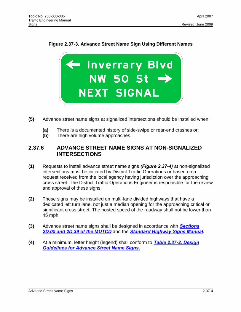
Topic No. 750-000-005 April 2007 Traffic Engineering Manual Signs Revised: June 2009
Advance Street Name Signs 2-37-4
Figure 2.37-3. Advance Street Name Sign Using Different Names
(5) Advance street name signs at signalized intersections should be installed when: (a) There is a documented history of side-swipe or rear-end crashes or; (b) There are high volume approaches.
2.37.6 ADVANCE STREET NAME SIGNS AT NON-SIGNALIZED
INTERSECTIONS (1) Requests to install advance street name signs (Figure 2.37-4) at non-signalized
intersections must be initiated by District Traffic Operations or based on a request received from the local agency having jurisdiction over the approaching cross street. The District Traffic Operations Engineer is responsible for the review and approval of these signs.
(2) These signs may be installed on multi-lane divided highways that have a
dedicated left turn lane, not just a median opening for the approaching critical or significant cross street. The posted speed of the roadway shall not be lower than 45 mph.
(3) Advance street name signs shall be designed in accordance with Sections
2D.05 and 2D.39 of the MUTCD and the Standard Highway Signs Manual.. (4) At a minimum, letter height (legend) shall conform to Table 2.37-2, Design
Guidelines for Advance Street Name Signs.

Topic No. 750-000-005 April 2007 Traffic Engineering Manual Signs Revised: June 2009
Advance Street Name Signs 2-37-5
Figure 2.37-4. Advance Street Name Signs at Non-Signalized Locations
2.37.7 ADVANCE STREET NAME PLAQUES ON INTERSECTION WARNING AND ADVANCE TRAFFIC CONTROL SIGNS
(1) Intersection Warning Signs (W2 series) (Figure 2.37-5) and Advance Traffic
Control Signs (W3 series) (Figure 2.37-6) should be installed when there is a documented need based on sight restriction, crash history, or engineering judgment. Advance street name plaques (Section 2C.49 of the MUTCD) should be installed on these warning signs when the following criteria are met:
(a) Minimum 2000 AADT (b) No street lighting along main arterial (c) Documented history of turning, entering, or side-swipe crashes (2) It is recommended that wherever a new or replacement Intersection Warning
Sign (W2 series) is installed on a rural roadway it is accompanied by an advance street name plaque designed in accordance with this section.
(3) Requests must be initiated by District Traffic Operations or may also be received
from the local agency having jurisdiction over the approaching cross street. (4) Advance street name plaques shall be black lettering on yellow background
using an 8-inch D series lettering size mounted below a 48-inch warning sign panel, in accordance with the FHWA’s Design Handbook for Older Drivers and Pedestrians. If not structurally possible, lettering size may be decreased to a minimum of 5-inch D series.
(5) Roads not currently signed with an advance route marker may be considered for
an Intersection Warning Sign (W2 series) with an advance street name plaque when they meet the criteria referenced in Section 2.37.7(1).

Topic No. 750-000-005 April 2007 Traffic Engineering Manual Signs Revised: June 2009
Advance Street Name Signs 2-37-6
Figure 2.37-5. Advance Street Name Plaque on Intersection Warning Sign
Figure 2.37-6. Advance Street Name Plaque on Advance Traffic Control Warning Sign

Topic No. 750-000-005 May 2007 Traffic Engineering Manual Signs
Use of Temporary Stop Signs 2-38-1
Section 2.38
USE OF TEMPORARY STOP SIGNS AT NON-FUNCTIONING SIGNALIZED INTERSECTIONS
2.38.1 PURPOSE The purpose of this section is to ensure motorist safety after a land falling hurricane. The Department’s guiding principles on deploying temporary stop signs shall conform to Section 316.1235, F.S., and to the MUTCD. This is intended only as a supplement to Section 316.1235, F.S. While this document is intended for the State Highway System, it can be used for local roadway systems as well.
2.38.2 CONDITIONS FOR USE
(1) The District Traffic Operations Engineer shall request the erection of temporary stop signs after an emergency event at locations where a signalized intersection is not functioning. A non-functioning signalized intersection is defined as an intersection that is equipped with traffic signals which are damaged and/or without power after an emergency event. When a signalized intersection is not functioning, then temporary stop signs should be installed when one of the following conditions is met:
(a) When the signalized intersection’s traffic signals are both damaged and/or
without power.
(b) When the signalized intersection is without power and restoration of power using a generator is not possible.
(2) When temporary stop signs are utilized at a signalized intersection that is not
functioning due to a power outage, the power shall be disconnected to avoid conflicts when power is restored.
2.38.3 LOCATION AND PLACEMENT (1) The locations for installation of temporary stop signs shall meet the conditions of
use in Section 2.38.2 and shall be at the discretion of the District Traffic Operations Engineer. The District Traffic Operations Engineer shall identify a list of critical signalized intersections to establish a priority for temporary stop sign installation.

Topic No. 750-000-005 May 2007 Traffic Engineering Manual Signs
Use of Temporary Stop Signs 2-38-2
(2) The placement of the temporary stop signs shall be in accordance with Figures 2.38-1 through 2.38-6 of this section. Placement of the temporary stop signs for any intersection design not represented in Figures 2.38-1 through 2.38-6 shall be done in accordance with the direction of the District Traffic Operations Engineer, the Department’s Design Standards, and the MUTCD.
2.38.4 STORAGE AND DISTRIBUTION (1) Each District shall store enough temporary stop signs to be deployed at 7.5
percent of the signalized intersections on the State Highway System in the District.
(2) The temporary stop signs shall be distributed by the District to the District
emergency response teams or emergency contractors on an as-needed basis. It shall be the responsibility of the District to develop a means of distribution to the District emergency response teams or the emergency contractors who will install them as indicated in Section 2.38.3.
2.38.5 REMOVAL AND RECOVERY (1) The temporary stop signs shall be removed at the same time the signals are
placed into operation. The recovery of the temporary stop signs shall be accomplished using District emergency response teams or emergency contractors by either of the following:
(a) Complete removal from each intersection.
(b) Stockpiling the temporary stop signs in one corner of the intersection for removal later.
(2) The Districts shall determine the method of recovery and develop a recovery plan
for their intersections.

Topic No. 750-000-005 May 2007 Traffic Engineering Manual Signs
Use of Temporary Stop Signs 2-38-3
Figure 2.38-1 Temporary Signing for Power Outage – Major Dual Left Intersection
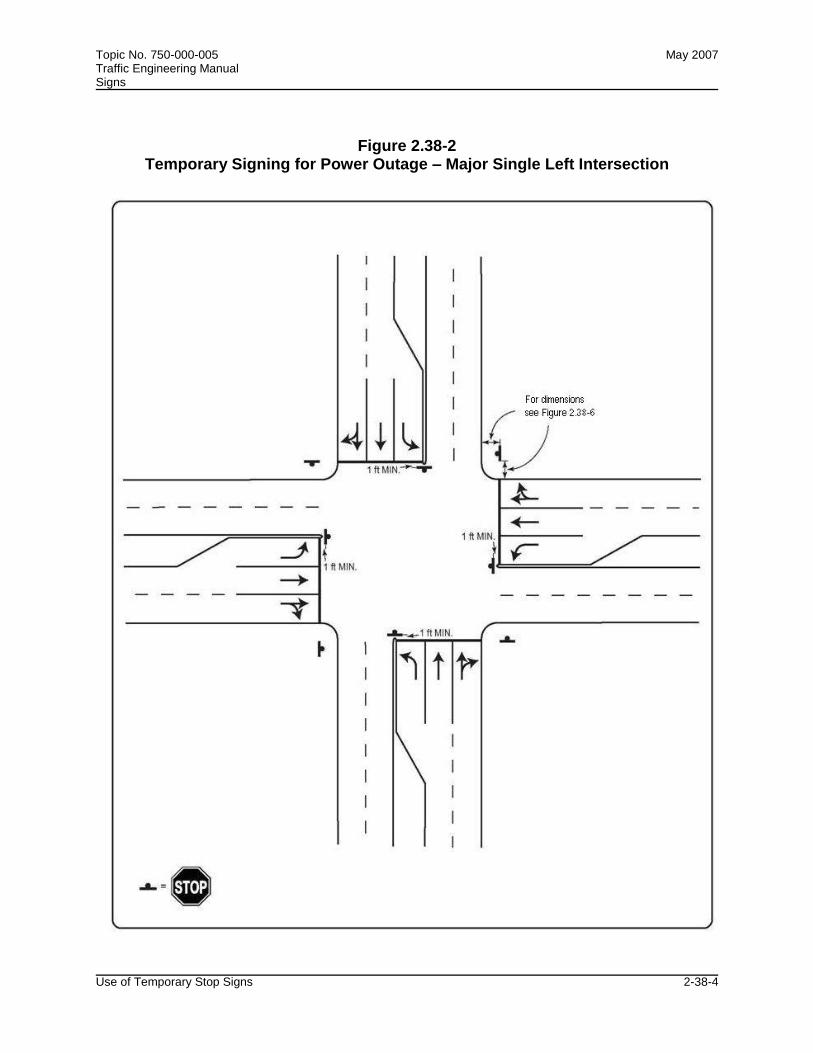
Topic No. 750-000-005 May 2007 Traffic Engineering Manual Signs
Use of Temporary Stop Signs 2-38-4
Figure 2.38-2 Temporary Signing for Power Outage – Major Single Left Intersection

Topic No. 750-000-005 May 2007 Traffic Engineering Manual Signs
Use of Temporary Stop Signs 2-38-5
Figure 2.38-3 Temporary Signing for Power Outage – Major Thru Intersection

Topic No. 750-000-005 May 2007 Traffic Engineering Manual Signs
Use of Temporary Stop Signs 2-38-6
Figure 2.38-4 Temporary Signing for Power Outage – Major to Minor Intersection

Topic No. 750-000-005 May 2007 Traffic Engineering Manual Signs
Use of Temporary Stop Signs 2-38-7
Figure 2.38-5 Temporary Signing for Power Outage – Minor Intersection

Topic No. 750-000-005 May 2007 Traffic Engineering Manual Signs
Use of Temporary Stop Signs 2-38-8
Figure 2.38-6 Temporary Signing for Power Outage – Sign Dimensions

Topic No. 750-000-005 October 2007 Traffic Engineering Manual Signs
Warning, Stop, and Yield Sign Sizes 2-39-1
Section 2.39
WARNING, STOP, AND YIELD SIGN SIZES
2.39.1 INTRODUCTION
(1) Drivers (65 years and older) experience visual decline and slower reaction time and reduced visual acuity is associated with repeat crash rates. Warning, STOP, and YIELD signs are critical to the safe operation of motor vehicles by all drivers. In order to determine the appropriate sizes that should be used for these critical signs, the State Traffic Engineering and Operations Office conducted a study.
(2) The minimum required corrected visual acuity to obtain a driver’s license in the State of Florida is 20/70. Therefore, this value was selected as the design visual acuity goal for these critical signs. Based on this design goal, the required sizes of Warning, STOP, and YIELD signs were determined and are presented in this section.
(3) The minimum sign sizes referenced in this section shall be used on all future
projects and as replacements when necessary due to sign damage or expiration of useful sign life.
2.39.2 RECOMMENDED WARNING SIGN SIZES
(1) The recommended symbol warning sign sizes in Table 2.39-1 meet the design goal for 20/70 visual acuity.
Table 2.39-1
RECOMMENDED SYMBOL WARNING SIGN SIZES
SIGN CODE SIGN SIZE
(inches) SIGN SYMBOL
W3-1 36 Stop Ahead
W3-2 36 Yield Ahead
W3-3 36 Signal Ahead
W3-5 36 Speed Reduction
W11-10 36 Truck Crossing

Topic No. 750-000-005 October 2007 Traffic Engineering Manual Signs
Warning, Stop, and Yield Sign Sizes 2-39-2
(2) The recommended word message warning sign sizes in Table 2.39-2 meet either the minimum design goal of 20/70 visual acuity or the most acuity available by using a 48-inch diamond shape sign.
Table 2.39-2
RECOMMENDED WORD MESSAGE WARNING SIGN SIZES
SIGN CODE
SIGN SIZE
(inches)
LETTER SERIES
PRIMARY LETTER HEIGHT (inches)
MINIMUM REQUIRED
ACUITY 20/x
SIGN MESSAGE
W5-1 48 D 8 64 Road Narrows
W5-2 48 D 8 64 Narrow Bridge
W5-3 48 C 8 54 One Lane Bridge
W8-1 36 D 10 80 Bump
W8-2 36 E 10 88 Dip
W8-3 48 C 8 54 Pavement Ends
W8-4 48 C 8 54 Soft Shoulder
W8-6 48 C 8 54 Truck Crossing
W8-7 48 D 8 64 Loose Gravel
W8-8 48 D 8 64 Rough Road
W8-9 48 C 8 54 Low Shoulder
W9-1 48 D 8 64 Right Lane Ends
W9-2 48 D 8 64 Lane Ends Merge Left
W13-1 24 E 10 88 35 MPH
W13-2 36 x 48 E 12 106 Exit 25 MPH
W13-3 36 x 48 E 12 106 Ramp 30 MPH
W14-1 48 D 9 72 Dead End
(3) A No Passing Zone sign (W14-3) shall be 36 x 48. In accordance with the
Standard Highway Signs Manual, 5-inch Series D lettering shall be used on the words NO and PASSING with 5-inch Series C lettering on the word ZONE.
(4) Right-of-way constraints may sometimes limit the size of warning signs. When
this occurs, the largest sign that will fit shall be used. (5) For any sign that isn’t designed for 20/70 visual acuity there will be less legibility
distance and therefore less time to perceive and understand the message before passing the sign. However, by adding the following additional distances to the

Topic No. 750-000-005 October 2007 Traffic Engineering Manual Signs
Warning, Stop, and Yield Sign Sizes 2-39-3
sign placement distances shown in Table 2C-4, Guidelines for Advance Placement of Warning Signs and referenced in Section 2C.05 of the MUTCD, the same total distance from the point where the sign is just legible to the condition must be maintained. Add 25 feet for 8-inch Series C and 8-inch Series D letters; 50 feet for 5-inch Series D, 6-inch Series C, and 6-inch Series D letters; and 75 feet for 5-inch Series C letters.
2.39.3 RECOMMENDED STOP SIGN SIZES
(1) The 48-inch STOP sign provides a minimum required acuity of only 20/45. In addition, use of the larger STOP signs, in areas with restricted right-of-way, may present problems. Installation of the STOP AHEAD symbol warning sign will alleviate both of these problems.
(2) Table 2.39-3 was produced to determine the required size for the STOP and
STOP AHEAD sign, and the sign placement distance for the STOP AHEAD sign.
Table 2.39-3
STOP AND STOP AHEAD SIGN SIZES AND PLACEMENT
POSTED SPEED (mph)
STOPPING SIGHT
DISTANCE (feet)
STOP SIGN SIZE1
(inches)
STOP SIGN RECOGNITION
DISTANCE (20/70) (feet)
STOP AHEAD
SYMBOL SIGNSIZE 2
(inches)
STOP AHEAD SIGN
PLACEMENT DISTANCE
(feet)
20 150 24 178 --- ---
25 200 30 222 --- ---
30 250 36 267 36* 125*
35 300 36 267 36* 175*
45 450 36 267 36 325
50 550 48 356 36 425
55 625 48 356 36 500
*If needed for restricted sight distance locations in urban areas. 1On state highways, the 48-inch STOP sign should be considered for 45 mph or greater. STOP signs on roads intersecting the state highway are usually replaced in FDOT construction projects. The sizes in this section are recommended for the replacement signs. Motorists traveling on local roads, in urban areas, expect to encounter STOP signs. STOP signs larger than 36-inches should be used when greater emphasis or visibility is needed. 2 On state highways, in rural areas, motorists may not expect to encounter a STOP sign. As an enhancement, the STOP AHEAD sign should be used for speeds equal to or greater than 45 mph. On local roads, in rural areas, motorists usually expect to stop as they cross a state highway. Where sight distance restrictions exist, a STOP AHEAD sign should be used.

Topic No. 750-000-005 October 2007 Traffic Engineering Manual Signs
Warning, Stop, and Yield Sign Sizes 2-39-4
(3) The stopping sight distance shown in the table above were calculated using the equation on Page 113 of AASHTO's A Policy on Geometric Design for Highways and Streets (Green Book, 2004 edition), and is for level, wet pavement. The brake reaction time was increased from 2.5 to 3.5 seconds to accommodate drivers aged 65 years and older.
(4) Both the stopping sight distance and the STOP AHEAD sign placement distance
should be increased to compensate for longer stopping sight distance on downgrades.
(5) The increase due to downgrades as steep as 6 percent does not change the
results in Table 2.39-3 for speeds up to and including 35 mph. Table 2.39-4 gives the required additional distance due to downgrade. This increase should be added to both the stopping sight distance and the STOP AHEAD sign placement distance in Table 2.39-3.
(6) The STOP AHEAD symbol sign should be placed according to Table 2.39-3,
rather than Table 2C-4, Guidelines for Advance Placement of Warning Signs, referenced in Section 2C.05 of the MUTCD for Condition B (Stop). The 36-inch size sign has 141 foot legibility for 20/70 visual acuity, which is greater than the required 125 feet.
(7) If restricted right-of-way requires a STOP sign smaller than shown in this table,
the largest possible size should be used and a 36-inch STOP AHEAD symbol sign should be placed according to Tables 2.39-3 and 2.39-4.
(8) If restricted right-of-way demands a STOP AHEAD symbol sign smaller than 36-
inch, the 30-inch sign will provide approximately 117 foot legibility. This sign should be placed 10 feet further from the STOP sign than the distance shown in Tables 2.39-3 and 2.39-4.
Table 2.39-4
ADDITIONAL STOPPING SIGHT DISTANCE AND STOP AHEAD SIGN PLACEMENT DISTANCE
DUE TO DOWNGRADE
POSTED SPEED (mph)
ADDITIONAL DISTANCE
(3% GRADE) (feet)
ADDITIONAL DISTANCE
(6% GRADE) (feet)
45 25 50
50 50 75
55 50 100

Topic No. 750-000-005 October 2007 Traffic Engineering Manual Signs
Warning, Stop, and Yield Sign Sizes 2-39-5
(9) When flashing beacons are used on the STOP sign, the STOP AHEAD sign is optional unless required because of restricted sight distance.
2.39.4 RECOMMENDED YIELD SIGN SIZES
Only the 36-inch size sign is required because it meets the design visual acuity goal. YIELD sign sizes for expressway and freeway use should continue to comply with the Standard Highway Signs Manual.

Topic No. 750-000-005 August 2008 Traffic Engineering Manual Signs
Displaying Messages on Dynamic Message Signs Permanently Mounted on the State Highway System 2-40-1
Section 2.40
DISPLAYING MESSAGES ON DYNAMIC MESSAGE SIGNS PERMANENTLY MOUNTED ON THE
STATE HIGHWAY SYSTEM 2.40.1 PURPOSE To provide a listing of approved standard safety messages that can be displayed on permanently mounted Dynamic Message Signs.
2.40.2 BACKGROUND The list of Approved Standard Safety Messages for Display on Permanently Mounted Dynamic Message Signs was originally part of Displaying Messages on Dynamic Message Signs Permanently Mounted on the State Highway System Policy (Topic No. 000-750-015).
2.40.3 DEFINITIONS Dynamic Message Sign (DMS). Refers to dynamic, changeable or variable message signs, defined as programmable traffic control devices that display messages composed of letters, symbols/graphics or both. They are used to provide information about changing highway conditions in order to improve operations, reduce accidents, and inform travelers. These signs may inform drivers to change travel speed, change lanes, divert to a different route, or simply to be aware of a change in current or future traffic conditions.
2.40.4 APPROVED STANDARD SAFETY MESSAGES FOR DISPLAY ON PERMANENTLY MOUNTED DMS
(1) Buckle Up / Save Lives (2) No Excuses / Buckle Up (3) Buckle Up / Just Do It (4) Click It / or Ticket (5) DUI Decide Before / You Drive (6) Prevent a Tragedy / Don’t Drink and Drive (7) Report Impaired Drivers / Dial * 347 (8) Report Reckless Drivers / Dial * 347 (9) An Alert Driver Can / Avoid a Crash (10) Keep Safe Distance / Stay Safe
Topic No. 750-000-005 August 2008 Traffic Engineering Manual Signs
Displaying Messages on Dynamic Message Signs Permanently Mounted on the State Highway System 2-40-2
(11) Move Over For Emergency Veh It’s The Law (12) Move Over A Lane For Emergency Veh It’s The Law

Chapter 3
SIGNALS

Topic No. 750-000-005 March 1999 Traffic Engineering Manual Signals Revised: December 2009
Signalized Intersection Flashing Mode Operation and Flashing Beacons 3-1-1
Section 3.1
SIGNALIZED INTERSECTION FLASHING MODE OPERATION AND FLASHING BEACONS
3.1.1 DEFINITIONS
(1) Flashing Beacon. A Flashing Beacon is a highway traffic signal with one or more signal sections that operates in a flashing mode. It can provide traffic control when used as an intersection control beacon or as a warning beacon in alternative uses.
(2) Flashing Operation of Traffic Control Signals:
(a) Non-Programmed Flashing Mode Operation. The automatic transfer from a signalized intersection's normal mode operation (stop and go, steady red-yellow-green displays) to flashing mode operation (stop or caution, flashing red-yellow, or red indications) caused by a malfunction of the signal controller, a conflict in signal displays or manual selection of the flashing mode operation by maintenance or police personnel.
(b) Programmed Flashing Mode Operation. The automatic transfer from a
signalized intersection’s normal mode operation (stop and go, steady red-yellow-green displays) to flashing mode operation (stop or caution, flashing red-yellow or red indications) during set times during the day.
3.1.2 RECOMMENDATIONS FOR SIGNALIZED INTERSECTIONS
3.1.2.1 Programmed Flashing Mode Operation
Flashing operation is both energy and operationally efficient and is encouraged when consistent with the following recommendations: (1) Flashing yellow/red operation may be used when two-way traffic volumes on the
main street are below 200 vehicles per hour. (2) Flashing yellow/red operation may be used during any hours of the day or night
when MUTCD Signal Warrants #1 and #2 are not met and where the two-way main street volume is greater than 200 vehicles per hour, provided the ratio of main street to side street volume is greater than 4:1.

Topic No. 750-000-005 March 1999 Traffic Engineering Manual Signals Revised: December 2009
Signalized Intersection Flashing Mode Operation and Flashing Beacons 3-1-2
(3) Signal operation should be changed to regular operation if crash pattern or severity increases or there is an increase in conflicts.
(4) A speedway effect can be avoided and uniform speeds obtained by maintaining
sufficient signals cycling through steady red, green and yellow at proper spacing so as to provide signal progression at an appropriate speed.
(5) Traffic signals should be put on flashing operation primarily at simple traffic signal
controlled intersections where the side street drivers have an unrestricted view of approaching main street traffic. Intersections with more than four legs, skewed intersections (greater than 15 degrees), or railroad preempted signals should not be considered for flash.
(6) Flashing should be restricted to no more than 3 separate periods in a 24-hour
period.
3.1.2.2 Non-Programmed Flashing Mode Operation
All signalized intersections shall automatically transfer to flashing mode immediately (no clearance interval) whenever a malfunction occurs during the normal mode operation of the signalized intersection.
3.1.3 APPLICATION REQUIREMENTS FOR SIGNALIZED INTERSECTION
The signal flashing mode and start-up sequence shall be as follows for: Yellow-Red Flashing Mode: (1) Main Street. Flashing yellow during flashing mode, then steady green on start-up
sequence. (2) Protected Left Turns. Flashing red during flashing mode, then steady red on
start-up sequence. Protected left turn signals should carry all arrow indications. (3) Side Street. Flashing red during flashing mode, then steady red on start-up
sequence. Red-Red Flashing Mode: (1) Main Street. Flashing red during flashing mode, then steady green on start-up
sequence.

Topic No. 750-000-005 March 1999 Traffic Engineering Manual Signals Revised: December 2009
Signalized Intersection Flashing Mode Operation and Flashing Beacons 3-1-3
(2) Protected Left Turns. Flashing red during flashing mode, then steady red on start-up sequence. Protected left turn signals should contain all arrow indications.
(3) Side Street. Flashing red during flashing mode, then steady red on start-up
sequence.
3.1.4 HEADS TO BE FLASHED
Section 4D.11 of the MUTCD requires all signal faces on an approach to be flashed when the signal is in flashing mode operation. Therefore, a left or right turn signal not illuminated during flashing mode operation is unacceptable. Section 4D.11 of the MUTCD requires the flashing of red or yellow arrow indications. Pedestrian signal indications (WALK and DON’T WALK) shall not be illuminated during flashing mode operation at signalized intersections.
3.1.5 FLASHING INDICATION COLORS
(1) The color to be flashed, red or yellow circular indication, or arrow indications shall be determined as follows:
(a) Each approach or separately-controlled turn movement that is controlled
during normal stop-and-go operation shall be provided with a flashing display.
(b) All signal faces on an approach shall flash the same color, either yellow or
red circular or arrow. However, separate signal faces for separately-controlled turn movements may be flashed as described in Section 4D.11 of the MUTCD. Flashing yellow indications for through traffic do not have to be shielded or positioned to prevent visual conflict for drivers in separately-controlled turn lanes; however, shielding for separate protected turn movements shall be in accordance with Sections 4D.06 and 4D.07 of the MUTCD.
(c) When a signal face consisting entirely of arrow indications is to be put on
flashing operation, or when a signal face contains no circular indication of the color that is to be flashed, the appropriate red or yellow arrow indication shall be flashed.
(d) When a signal face includes both circular and arrow indications of the
color that is to be flashed, only the circular indication of that color shall be flashed. A 5-section head cluster shall be flashed the same color as the approach through lanes. Only circular red or circular yellow indications shall be flashed in a flashing mode operation.

Topic No. 750-000-005 March 1999 Traffic Engineering Manual Signals Revised: December 2009
Signalized Intersection Flashing Mode Operation and Flashing Beacons 3-1-4
(e) No steady green indication or flashing yellow indication shall be
terminated and immediately followed by a steady red or flashing red indication without the display of the steady yellow change indication; however, transition may be made directly from a steady green indication to a flashing yellow indication. This applies to both the circular and arrow indications. The transition from stop-and-go to flashing operation, when the transition is initiated by a signal conflict monitor or by a manual switch, may be made at any time.
(2) Main Street, Through Traffic. From flashing yellow to steady green. (3) Main Street, Separate Left Turn. From flashing red to steady red. (4) Side Street, Through Traffic. From flashing red to steady red. (5) Green arrow indications which are continuously illuminated during normal
operations should be continually illuminated during flashing mode operation.
3.1.6 APPLICATION REQUIREMENTS FOR FLASHING BEACONS
(1) All existing flashing beacons are considered to meet the MUTCD requirements whether they are single or dual indicated.
(2) However, all new or replacement intersection control beacon installations shall
be designed and installed with dual indications. Wherever practical, the dual indications shall both be positioned laterally within each approach width to the intersection. For example, a four-way beacon assembly over each side of a divided four-lane highway does not meet this requirement. In no instance shall intersection control beacon indications on an approach be closer than 8 feet apart measured horizontally.
3.1.7 OPERATION OF FLASHING BEACONS
(1) Intersection Control Beacons. Dual indications for intersection control beacons displaying horizontally aligned red indications shall be flashed simultaneously. Alternate flashing of dual horizontally aligned red indications is reserved for highway approaches to a railroad. Two vertically aligned red signal indications shall be flashed alternately. Refer to Section 4K.02 of the MUTCD.
(2) Warning Beacons. Warning beacons typically are installed at obstructions or to
emphasize warning signs. These may be singular or dual indications and may be flashed alternately or simultaneously. Refer to Section 4K.03 of the MUTCD.

Topic No. 750-000-005 March 1999 Traffic Engineering Manual Signals Revised: December 2009
Guidelines for Left Turn Treatments 3-2-1
Section 3.2
GUIDELINES FOR LEFT TURN TREATMENT
3.2.1 PURPOSE
This guideline can be used to determine the selection of the following types of left turn treatments, as defined in Section 4D.07 of the MUTCD: • Permissive Only Mode • Protected/Permissive Mode • Protected Only Mode • Split Phasing (each direction alternatively has both left turn green arrow and
circular green)
3.2.2 LEFT TURN SIGNAL PHASING
(1) If the need for left turn phasing on an intersection approach has been firmly established, the following guidelines should be used to select the type of left turn phasing to provide. Sound traffic engineering judgment should be exercised in applying these guidelines.
(2) A protected/permissive mode should be provided for all intersection approaches
that require a left turn phase unless there is a compelling reason for using another type of left turn phasing. If the decision between providing protected/permissive or protected only mode is not obvious, the traffic engineer should initially operate the left turn phase as protected/permissive mode on a trial basis. If satisfactory operations result, the protected/permissive mode should be retained. If unsatisfactory operations result, the protected/permissive mode should be converted to protected only mode.
(3) A protected only mode shall be provided for an intersection approach if any of the
following conditions exist: (a) Two or more left turn only lanes are provided. (b) Geometric conditions and resulting sight distance necessitate protected
only mode. (c) The approach is the lead portion of a lead/lag intersection phasing sequence.
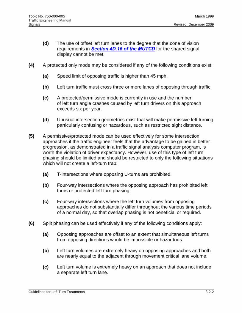
Topic No. 750-000-005 March 1999 Traffic Engineering Manual Signals Revised: December 2009
Guidelines for Left Turn Treatments 3-2-2
(d) The use of offset left turn lanes to the degree that the cone of vision requirements in Section 4D.15 of the MUTCD for the shared signal display cannot be met.
(4) A protected only mode may be considered if any of the following conditions exist:
(a) Speed limit of opposing traffic is higher than 45 mph.
(b) Left turn traffic must cross three or more lanes of opposing through traffic. (c) A protected/permissive mode is currently in use and the number
of left turn angle crashes caused by left turn drivers on this approach exceeds six per year.
(d) Unusual intersection geometrics exist that will make permissive left turning
particularly confusing or hazardous, such as restricted sight distance. (5) A permissive/protected mode can be used effectively for some intersection
approaches if the traffic engineer feels that the advantage to be gained in better progression, as demonstrated in a traffic signal analysis computer program, is worth the violation of driver expectancy. However, use of this type of left turn phasing should be limited and should be restricted to only the following situations which will not create a left-turn trap:
(a) T-intersections where opposing U-turns are prohibited. (b) Four-way intersections where the opposing approach has prohibited left
turns or protected left turn phasing. (c) Four-way intersections where the left turn volumes from opposing approaches do not substantially differ throughout the various time periods of a normal day, so that overlap phasing is not beneficial or required. (6) Split phasing can be used effectively if any of the following conditions apply: (a) Opposing approaches are offset to an extent that simultaneous left turns from opposing directions would be impossible or hazardous. (b) Left turn volumes are extremely heavy on opposing approaches and both are nearly equal to the adjacent through movement critical lane volume. (c) Left turn volume is extremely heavy on an approach that does not include a separate left turn lane.

Topic No. 750-000-005 March 1999 Traffic Engineering Manual Signals Revised: December 2009
Guidelines for Left Turn Treatments 3-2-3
(d) Drivers are permitted to turn left from more than one lane, but drivers are also permitted to use the right-most left turn lane as a through lane.
3.2.3 LEFT TURN SIGNAL DISPLAYS
The following are the left turn signal displays as referenced in Section 4D.07 of the MUTCD to be used with the various types of left turn phasing. (1) Protected/Permissive Mode. A 5-section signal display centered over the lane
line between the left turn lane and the left-most through lane should be used. The 5-section signal display could serve as one of the two required through traffic signal heads. No supplemental signing should be provided.
(2) Protected Only Mode with a single left turn lane. A 3-section vertical signal
head from top to bottom -- (or left to right in a horizontally-aligned face) left turn red arrow, left turn yellow arrow, left turn green arrow) should be centered over the left turn lane.
(3) Protected Only Mode with two or more left turn lanes. At least two 3-section
vertical signal heads (or left to right in a horizontally-aligned face) as described in the paragraph above should be used with one centered over each left turn lane.
(4) Split phasing. A 5-section signal display centered over the lane line between
the left turn lane and the left-most through lane should be used. The 5-section signal display could serve as one of the two required through traffic signal heads. No supplemental signing should be provided.
3.2.4 SIGNAL DISPLAY FOR EXCLUSIVE LEFT TURN LANE
A 3-section (red, yellow, and green) signal face shall not be placed over, and/or devoted to, an exclusive left turn lane, unless the signal phasing sequence provides a protected left turn movement during the cycle.
3.2.5 LEFT TURN PHASES FOR SEPARATED LEFT AND THRU LANES
(1) Left turn lanes at signalized intersections that are separated from through lanes by raised or painted islands may be operated as protected only mode, as protected/permissive or permissive only mode. If protected/permissive mode is used, the 5-section signal display should be placed overhead on the lane line between the adjacent through lane and the island so as to be obvious that the signal display is shared. In all cases, the cone of vision requirements in Section 4D.15 of the MUTCD shall be met. Below is an illustrative example using standard lane widths on a 4-lane divided highway. A corresponding table for

Topic No. 750-000-005 March 1999 Traffic Engineering Manual Signals Revised: December 2009
Guidelines for Left Turn Treatments 3-2-4
maximum allowable island width (without shifting the signal head) for the indicated signal head distance from stop line is given.
Figure 3.2-1. Signal Head/Left-turn Treatment

Topic No. 750-000-005 March 1999 Traffic Engineering Manual Signals Revised: December 2009
Guidelines for Left Turn Treatments 3-2-5
Table 3.2-2. Maximum Width of Hatched-Out Area Without Shifting Signal Head
Horizontal Distance Width
40 8
50 12
60 15
70 19
80 23
90 26
100 30
110 34
120 37
130 41
140 44
150 48
(2) Signal faces containing circular green signal indication for a permissive only left-turn should not be located above an exclusive left-turn lane or the extension of the lane, nor should they be post-mounted on the far side median in front of the left-turn lane. Permissive only left turn signal displays shall not be provided in an exclusive left turn signal face. If the separation or geometric conditions of the offset left turn lane is such that the cone of vision would not be met with a shared signal head positioned on the lane line adjacent to the nearest through lane, the shared signal face may be offset to the left from the adjacent through lane line such that the required cone of vision is still met for the right most through lane and for the left turn lane. This lateral offset spacing should be used only after other options such as increasing the horizontal distance to the signals heads has been considered and placed so as to be obvious that the signal display is shared. The lateral offset spacing of the shared signal head from the adjacent through lane generally should not be greater than one half the width of the island (½ W).
(3) If the lateral shift is too great, the cone of vision may not be adequate for the driver in the right most through lane. Where the cone of vision cannot be met, protected only mode must be used. This may be due to a large parallel offset left turn lane or due to a tapered or curved offset left turn lane.

Topic No. 750-000-005 March 1999 Traffic Engineering Manual Signals Revised: December 2009
Guidelines for Left Turn Treatments 3-2-6
Figure 3.2-3. Left Turn Lane Signal Head Shift
3.2.6 PERMISSIVE ONLY MODE IN MULTI- LEFT TURN LANE APPROACHES
A permissive green interval for two or more left turn lane approaches shall not be used.

Topic No. 750-000-005 March 1999 Traffic Engineering Manual Signals
Scheduling Traffic Signal Studies and Funding Arrangements 3-3-1
Section 3.3
SCHEDULING TRAFFIC SIGNAL STUDIES AND FUNDING ARRANGEMENTS
3.3.1 PURPOSE
To establish criteria for responding to requests for traffic signal installations, for funding and implementation arrangements for warranted signals and scheduling related studies to determine need.
3.3.2 GENERAL
Since the Department is charged with the responsibility to erect and maintain a uniform system of traffic signals and other traffic control devices for regulation, control, guidance, and protection of traffic on the State Highway System, there is need to provide uniformity in responding to requests for signals and in the scheduling and conducting of traffic studies to determine signal needs.
3.3.3 RESPONSE TO SIGNAL REQUESTS AND SCHEDULING TRAFFIC SIGNAL STUDIES
(1) The District Traffic Operations Office shall objectively review all requests for traffic signal installations received by the Department against existing information and local knowledge of the intersection before agreeing to commit resources for a detailed traffic study. This initial screening may require a brief site visit to view the field conditions. During the initial screening, all data shall be recorded in writing and kept on file. An attempt shall be made to relate all data and analysis to standards set forth in the MUTCD. If the initial screening results in a decision to conduct a signal warrant study, the District Traffic Operations Office should contact the local government traffic engineering agency, advise them of the Department’s decision, and obtain their views and input.
(2) If the initial screening results in a decision to not consider signalization or further
study, the District Traffic Operations Office shall document the reasons and advise the requestor of the findings with a copy to the local government traffic engineering agency. Although local government concurrence is desirable, it is not a prerequisite for committing Department resources to a full signal warrant study.
(3) The District Traffic Operations Office shall normally conduct signal warrant
studies for proposed signal installations on the State Highway System. However,

Topic No. 750-000-005 March 1999 Traffic Engineering Manual Signals
Scheduling Traffic Signal Studies and Funding Arrangements 3-3-2
a local government traffic engineering agency may conduct such studies and submit them to the District Traffic Operations Office for review. All studies shall be conducted in accordance with the procedure and standards prescribed in this document and shall be signed and sealed by a professional engineer.
(4) Formal legal resolutions from local agencies may form the basis of their
concurrence in the need for a traffic signal study. However, such documents should not be required by the Department as a prerequisite to scheduling the study. Additionally, the availability of implementation funds should not be a prerequisite to assessing traffic signalization needs (conducting a study).
(5) The District Traffic Operations Office shall keep a log of requests for traffic signal
studies and their disposition. To the extent practical, a priority system utilizing the request date, traffic volumes, accident experience, and the level of local government interest should be used to schedule traffic signal studies.
3.3.4 TRAFFIC SIGNAL STUDIES AND ENGINEERING
(1) Department of Transportation staff, local agency engineers or qualified consulting engineers may perform studies for traffic signals and provide any required engineering services for the preparation of implementation plans and specifications for proposed traffic signals on the State Highway System. However, the Department is responsible for requiring and overseeing such work.
(2) Traffic signal studies shall be made in accordance with Department Topic No.
750-020-007, Uniform Traffic Engineering Studies, particularly, Chapter 12 of the Manual on Uniform Traffic Studies (MUTS), referred therein. Plans and specifications, if required, shall be prepared in accordance with established Department procedures.
(3) Traffic signal studies or engineering analyses conducted for new, or proposals for
significantly revised, private access points to major traffic generators shall be conducted by qualified traffic engineers at no cost to the Department. Except under unusual circumstances, these studies and/or analyses shall be part of the Driveway Permit Application as per the requirements of Rule 14-96. These studies shall, in addition to evaluating the need for signal control at unsignalized intersections, also consider enhanced features at existing signalized intersections, as appropriate. Such study and report shall be signed and sealed by a professional engineer. Likewise, engineering costs associated with the preparation of implementation plans and specifications should also normally be borne by the developer. There may be instances where the Department determines that specific critical design requirements make it essential that the engineering work be performed by Department forces. In such instances, the

Topic No. 750-000-005 March 1999 Traffic Engineering Manual Signals
Scheduling Traffic Signal Studies and Funding Arrangements 3-3-3
District Secretary may direct that the engineering work be done by the Department at no cost to the developer.
(4) Studies and engineering at existing private access points which may be required
as a result of normal traffic growth are usually made by qualified traffic engineers by the requestor. In extraordinary situations the Department may elect to do so.
3.3.5 FUNDING ARRANGEMENTS FOR WARRANTED NEW SIGNAL INSTALLATIONS
(1) New traffic signal installations on the State Highway System may be funded from private, local, state, or federal funds, or any combination of such funds.
(2) The developers shall totally fund the installation of any new traffic signal and/or
the enhancements of any existing traffic signals when these improvements are requirements specified in a new or revised Driveway Permit or local government Development Order. If proposals to provide signalization or modify existing signalization is above the minimum required by Permit or Development Order and provides a betterment to the State Highway System substantially beyond mitigation for development impacts, the Department’s District Secretary may determine an appropriate financial participation formula and assign percentages of participation to the developer in consideration of the specific conditions at each site.
(3) Although signal installation on the State Highway System is the responsibility of
the Department, local governments may contribute, on a voluntary basis, a portion, or all of the cost of signal installation depending upon specific cooperative arrangements worked out between the Department’s District Offices and the local agency. Local funds are most often utilized in these cooperative efforts to advance the implementation schedule of a warranted traffic signal. When local funds are accepted by the Department, a formal joint project agreement executed by both parties is necessary.
(4) Most local governments in Florida’s urban areas have qualified traffic engineering
organizations with experienced traffic signal field crews and many new signals have been installed on the State Highway System using local agency installation crews with control hardware supplied by the Department. Where the local agency is agreeable to this procedure (most are because of their maintenance and operational involvement in these sites), this technique should be encouraged. No formal agreement is necessary since no money is changing hands; however, a letter from the local agency agreeing to install Department supplied hardware should be obtained.

Topic No. 750-000-005 March 1999 Traffic Engineering Manual Signals
Scheduling Traffic Signal Studies and Funding Arrangements 3-3-4
3.3.6 OTHER CONSIDERATIONS
(1) Prior to purchase, use, or installation, traffic signals must comply with provisions of Section 7.1, Certification and Approval of Traffic Control Devices, in this manual (former Department Topic No. 750-010-013).
(2) Prior to installation of traffic signals, provisions of Department Topic No. 750--
010-022, Traffic Signal Maintenance Agreements, should be complied with.

Topic No. 750-000-005 March 1999 Traffic Engineering Manual Signals Revised: February 2010
Emergency Traffic Control Signals 3-4-1
Section 3.4
EMERGENCY TRAFFIC CONTROL SIGNALS
3.4.1 PURPOSE
To provide guidance for warranting, designing, and operating emergency traffic control signals at locations where emergency vehicles, most commonly fire trucks, need special traffic signal assistance to egress onto the street system.
3.4.2 BACKGROUND
The Department’s district offices often receive local public agency requests for traffic signal control for the departure of emergency vehicles. This section was developed to give comprehensive guidance to determine if the signals are warranted.
3.4.3 PROCEDURE
The need for an Emergency Traffic Control Signal shall be considered if an engineering study finds that one of the following warrants are met: (1) Minimum Traffic Volumes (Both directions of travel, based on signal warrant #2),
as shown in Table 3.4-1.
Table 3.4-1. Minimum Traffic Volumes
Roadway Peak Hour or 24 Hours
2-Lane 750 VPH 7500 ADT
4-Lane 900* VPH 9000* ADT
6-Lane or more 1200* VPH 12000* ADT
*Values shall be increased by 1/3 when arterial has traffic signal system coordination with signals located within 1000 feet in both directions from the emergency signal location.
(2) When the geometric design of the arterial and emergency vehicle facility is such that the vehicle when returning must back in, and to do so must block traffic when performing this maneuver and the traffic volume and speeds are such that the use of emergency vehicle lights and flaggers have been ineffective in controlling traffic.
(3) When the location of the emergency vehicle driveway consistently conflicts with
the normal traffic queue from an adjacent signalized intersection. The use of DO NOT BLOCK INTERSECTION (R10-7) sign should be considered in conjunction with the emergency signal installation.

Topic No. 750-000-005 March 1999 Traffic Engineering Manual Signals Revised: February 2010
Emergency Traffic Control Signals 3-4-2
(4) On all approaches when vertical or horizontal curvature or other obstructions do not provide adequate stopping sight distance for traffic approaching an emergency vehicle driveway.
3.4.4 CONFIGURATION AND OPERATION OF EMERGENCY TRAFFIC CONTROL SIGNALS
(1) Section 4F.03 of the MUTCD defines the operational requirements for a mid-block location of an emergency signal. The MUTCD allows either a steady green or flashing yellow operation of signal heads between emergency vehicle actuations. These choices of operation, combined with limited details for signal configuration requirements have resulted in a lack of uniformity of emergency signal design and operation within the State, therefore, the following criteria shall be followed.
(2) Based on requirements contained in Chapter 4F of the MUTCD, the following
criteria for emergency traffic control signals shall be followed for new or reconstructed installations.
(a) Dual indications shall be provided for each roadway approach. A minimum
of one signal face shall be installed for the emergency vehicle driveway but two indications are preferable.
(b) If the emergency service is located off the main roadway and emergency
vehicles access the main roadway via a public access street, emergency signals may be erected at the intersection of these roadways. If this practice is followed, dual indication shall be used on the public access street, with the signals resting on the flashing red indication.
(c) Mid-block emergency signals shall be operated as flashing yellow
between emergency vehicle actuations. Roadway signal head configuration shall consist of three sections and shall be operated as shown in Figure 3.4-2. (The use of special technological signal devices may be selected, i.e., strobe signals, LED, or solar power. These devices may require temporary permitting prior to installation.)
(d) Signal operation at intersections which are pre-empted by emergency
vehicles entering the roadway near or at the intersection should be designed on an individual basis.
(3) It is not practical to outline all possible situations which may be encountered in
the field. Such factors as emergency vehicle route distance between the intersection and emergency vehicle driveway, intersection geometrics, number of lanes, normal queue length, traffic volumes, etc., should be considered.

Topic No. 750-000-005 March 1999 Traffic Engineering Manual Signals Revised: February 2010
Emergency Traffic Control Signals 3-4-3
3.4.5 EMERGENCY SIGNAL SIGN (R10-13)
(1) As emergency signals are installed at locations along major arterials where emergency vehicles enter the roadway, the EMERGENCY SIGNAL sign (R10-13), as shown on Page 145 in the FHWA’s Standard Highway Signs Manual shall be placed on the span wire or mast arm to identify the purpose of the signal to the driver.
(2) The EMERGENCY SIGNAL sign (R10-13) shall be legible at all times, shall be
mounted adjacent to each signal face, and shall be located between the dual signal indications on each roadway approach.
(3) No sign is required for the emergency vehicle driveway approach.
3.4.6 OTHER REQUIREMENTS
(1) A controller timing chart shall be a part of the contract plans. (2) A Maintenance Agreement shall be required for all Emergency Signals on the
State Highway System. (3) A signal timing study is required to determine proper clearance intervals.

Topic No. 750-000-005 March 1999 Traffic Engineering Manual Signals Revised: February 2010
Emergency Traffic Control Signals 3-4-4
Figure 3.4-2. Mid-Block Emergency Signal Operation
SIGNAL NORMAL
OPERATION
CHANGE TO EMERGENCY PRE-EMPTION
EMERGENCY PRE-EMPTION
CHANGE FROM
EMERGENCY PRE-EMPTION RELEASE
1,2,3,4 G or FY Y R R G or FY
5,6 BLANK BLANK G BLANK BLANK

Topic No. 750-000-005 March 1999 Traffic Engineering Manual Signals Revised: February 2010
Traffic Signal Mast Arm Support Boundaries 3-5-1
Section 3.5
TRAFFIC SIGNAL MAST ARM SUPPORT BOUNDARIES
3.5.1 GENERAL
The Department’s Plans Preparation Manual, Topic No. 625-000-007, Volume 1 – Chapter 7 requires that all traffic signals installed on the State Highway System that are within the Mast Arm Structures Boundary shall be supported by mast arms.
3.5.2 IMPLEMENTATION
3.5.2.1 Mast Arm Structures Boundary Maps
The mast arm structures boundary map follows an alignment of State Roads that are parallel to an approximate ten mile distance to the coastline. Official mapping of this boundary is maintained on a Map Info-Base by the State Traffic Engineering and Operations Office. Links to current district maps are provided below: District 1 District 2 District 3 District 4 District 5 District 6 District 7

Topic No. 750-000-005 June 2002 Traffic Engineering Manual Signals Revised: July 2011
Standardization of Yellow and All-Red Intervals 3-6-1 for Signalized Intersections
Section 3.6
STANDARDIZATION OF YELLOW AND ALL- RED INTERVALS FOR SIGNALIZED INTERSECTIONS
3.6.1 PURPOSE The purpose of the yellow change and all-red clearance intervals is to provide a safe transition between two conflicting traffic signal phases. The function of yellow change interval is to warn traffic of an impending change in the right-of-way assignment and the function of the all-red clearance interval is to provide additional time following the yellow change interval to clear the intersection before conflicting traffic is released. The MUTCD states that a yellow change interval should have a minimum duration of 3 seconds and a maximum duration of 6 seconds and a red clearance interval should have a duration not exceeding 6 seconds. The intent of this section is to provide a State standard for uniform application of the minimum yellow and all-red intervals. All new signals installations, intersections with Traffic Infraction Devices, signal phasing changes, geometric changes affecting the timing or phasing, or corridor re-timing projects must comply with these guidelines immediately upon implementing timing changes. All other existing signalized intersections on the state highway system must be in compliance with guidelines of this Section by January 1, 2015. 3.6.2 STANDARD (1) Section 316.075(3)(a), F.S. states that no traffic control signal device shall be
used which does not exhibit a yellow or "caution" light between the green or "go" signal and the red or "stop" signal. The Statute is silent on the yellow clearance interval duration and does not mention nor mandates the use of an all red clearance interval.
(2) Section 316.075(1)(c)(1), F.S. requires “Vehicular traffic facing a steady red
signal shall stop before entering the crosswalk on the near side of the intersection or, if none, then before entering the intersection and shall remain standing until a green indication is shown.”
(3) Section 316.075(1)(a),F.S. requires “Vehicular traffic facing a circular green
signal may proceed cautiously straight through or turn right or left unless a sign at such place prohibits either such turn. But vehicular traffic, including vehicles turning right or left, shall yield the right-of-way to other vehicles and to pedestrians lawfully within the intersection or an adjacent crosswalk at the time such signal is exhibited.”

Topic No. 750-000-005 June 2002 Traffic Engineering Manual Signals Revised: July 2011
Standardization of Yellow and All-Red Intervals 3-6-2 for Signalized Intersections
(4) Approach speed used in this section is the posted speed or the 85th percentile approach speed for the lanes being analyzed. Through lane and turn lane approach speeds on an approach may be different. According to Section 5.3 of the Federal Highway Administration’s Signal Timing Manual, “When applying Equation 5-2 to left-turn movement phases, the speed used should reflect that of the drivers that intend to turn. This speed can equal that of the adjacent through movement but it can also be slower as left-turn drivers inherently slow to a comfortable turning speed.”
(5) Yellow change and all-red clearance intervals specified herein are minimums,
and should be increased as necessary, based on professional engineering judgment, to fit site conditions at any particular intersection.
3.6.2.1 Yellow Change Interval The Florida yellow change intervals shown in Table 3.6-1, are computed using the ITE formula (Formula 3.6-1, found in ITE’s Traffic Engineering Handbook). These intervals are the required minimums. If necessary and due to equipment limitations, round computed values up to the next 0.5 second.
Table 3.6-1. Florida Yellow Change Interval (0.0 % Grade)*
APPROACH SPEED (MPH)
YELLOW INTERVAL (SECONDS)
25 3.0 30 3.2 35 3.6 40 4.0 45 4.3 50 4.7 55 5.0 60 5.4 65 5.8
* For approach grades other than 0%, Use ITE Formula.

Topic No. 750-000-005 June 2002 Traffic Engineering Manual Signals Revised: July 2011
Standardization of Yellow and All-Red Intervals 3-6-3 for Signalized Intersections
Formula 3.6-1
𝑌𝑌 = 𝑡𝑡 + 1.47𝑣𝑣
2(𝑎𝑎 + 𝐺𝐺𝑔𝑔)
Where: Y = length of yellow interval, sec.
t = perception-reaction time, (Use 1 sec.). v = speed of approaching vehicles, in mph.
a= deceleration rate in response to the onset of a yellow indication. (Use 1ft/sec2) g = acceleration due to gravity. (Use 32.2 ft/sec2)
G= grade, with uphill positive and downhill negative. (percent grade /100) 3.6.2.2 All-Red Clearance Interval An all-red clearance interval must be used. Providing adequate all-red clearance intervals can significantly impact intersection safety by reducing the probability of occurrence of right angle crashes, even if drivers run the red signal indication. The all-red clearance interval values are computed using Formula 3.6-2, found in ITE’s Traffic Engineering Handbook.
Formula 3.6-2
𝑅𝑅 =𝑊𝑊 + 𝐿𝐿1.47𝑣𝑣
Where: R = length of all-red interval, sec.
W = total traversed width, from the approach stop bar to the far side of no-conflict point.
L = Length of vehicle (Use 20 ft.) v = speed of approaching vehicles, in mph.
3.6.2.3 Turn Phases (1) Protected Turns. For protected left or right turns the yellow and all-red intervals
shall be computed using Formulas 3.6-1 and 3.6-2 where the speed is based on the turning movement’s lane speed.
(2) Protected/Permissive Turns. For protected left or right turns, the yellow and all-
red intervals shall be computed based on the lane speed. For permissive left or right turns, the yellow and all-red intervals are determined by the concurrent through phase.
Topic No. 750-000-005 March 1999 Traffic Engineering Manual Signals
Audible Pedestrian Signals 3-7-1
Section 3.7
AUDIBLE PEDESTRIAN SIGNALS
3.7.1 PURPOSE
To establish criteria for the installation and operation of audible pedestrian signal heads on the State Highway System.
3.7.2 GENERAL
(1) Section 4E.06, Accessible Pedestrian Signals of the MUTCD establishes the standards for which audible pedestrian signals shall be installed on the State Highway System. Section 4E.06 also contains guidance and support that should be reviewed and considered on any audible signal installation request.
(2) The MUTCD does state that pedestrians with vision disabilities who cross streets at signalized intersections initiate their crossing when they hear the traffic in front of them stop and the traffic alongside them begin to move, corresponding to the onset of the green interval. This technique is effective at most signalized intersections, therefore, the vast majority of signalized intersections will not require any audible pedestrian signals.
3.7.3 PROCEDURE
(1) Any audible pedestrian signal that is installed on the State Highway System shall be reviewed and approved by the District Traffic Operations Engineer prior to installation.
(2) Requests for audible signal installations received from the public, maintaining agencies, or agencies and/or support groups for the visually impaired shall be reviewed by the District Traffic Operations Engineer with input, if necessary, from visually impaired agencies and/or support organizations to determine if the audible signal would be effective and/or safe for operation.
(3) An engineering study shall be conducted if the initial District Traffic Operations
Engineer’s review supports the installation of the audible pedestrian signal.
(4) The following criteria should be considered before approving an audible pedestrian signal.
(a) Engineering study to assess the need. (b) Right on red movements.

Topic No. 750-000-005 March 1999 Traffic Engineering Manual Signals
Audible Pedestrian Signals 3-7-2
(c) Continuous right turn movements. (d) Complexity of signal phasing. (e) Complexity of intersection geometry. (f) Traffic volumes during times when pedestrians might be present. (g) Audible tones or sounds that may cause confusion. (h) Verbal messages instead of tones or sounds. (i) Vibrotactile pedestrian devices. (j) Pushbutton or passive pedestrian detectors. (k) Sufficient audible above ambient noise, 89db (decibles) maximum.
(l) Installations at locations with more than four lanes and/or greater than 35 MPH posted speed limit shall be given additional considerations for geometrics, operations, and pedestrian safety.
(m) Consideration for audible signal installations other than at mid-block locations (i.e. transit corridors or hubs) shall be installed only after review and approval by the District Traffic Operations Engineer.
(5) If the proposed location is a wide crossing where pedestrian storage is required
in the median area, then an audible pedestrian signal installation is not recommended.
3.7.4 APPROVAL/DENIAL PROCESS
(1) The District Traffic Operations Engineer shall objectively review all requests for audible pedestrian signals received by the Department from an engineering study and/or local request before agreeing to approve the installation.
(2) The initial review may require a brief site visit to view the field conditions. During
the initial screening, all data shall be recorded in writing and kept on file. An attempt shall be made to relate all data and analysis to standards set forth in Section 4E.06 of the MUTCD.
(3) If the initial review results in a decision not to consider the audible pedestrian
signal head, the District Traffic Operations Engineer shall document the reasons and advise the requestor of the findings with a copy provided to local government’s Traffic Engineering Office. Although local government concurrence is desirable, it is not a prerequisite for committing Department resources for an audible pedestrian signal installation.

Topic No. 750-000-005 March 1999 Traffic Engineering Manual Signals Revised: January 2010
Mid-Block Pedestrian Crosswalks 3-8-1
Section 3.8
MID-BLOCK PEDESTRIAN CROSSWALKS
3.8.1 PURPOSE
To establish criteria for the installation and operation of mid-block pedestrian crosswalks on the State Highway System.
3.8.2 GENERAL
(1) Mid-block crosswalks are intended to improve pedestrian connectivity and reduce instances of pedestrians crossing at random, unpredictable locations – which can create confusion and add risk to themselves and other road users. Mid-block pedestrian crosswalks may be an appropriate tool to safely accommodate pedestrians at locations where there is a documented pedestrian demand and the spacing to the nearest intersection crossing location would result in significant out-of direction travel for pedestrians.
(2) Mid-block crosswalks that are well located and thoughtfully designed can serve
as a mechanism for improving pedestrian connections, community walkability, and pedestrian safety. However, they are not suitable for all locations and careful evaluation must be undertaken regarding expected levels of pedestrian crossing demand, safety characteristics of the crossing location, and design considerations for the crossing control type.
3.8.3 DEFINITIONS (1) Marked crosswalk. Any portion of a roadway at an intersection or elsewhere
distinctly indicated for pedestrian crossing by lines or other markings on the surface. Marked crosswalks serve to highlight the right-of-way where motorists can expect pedestrians to cross and designate a stopping or yielding location.
(2) Mid-block location. Any location proposed for a marked crosswalk on a
roadway with an uncontrolled approach. (3) Pedestrian attractor. A residential, commercial, office, recreational, or other
land use that is expected to be an end destination for pedestrian trips during a particular time of day.

Topic No. 750-000-005 March 1999 Traffic Engineering Manual Signals Revised: January 2010
Mid-Block Pedestrian Crosswalks 3-8-2
(4) Pedestrian generator. A residential, commercial, office, recreational or any other land use that serves as the starting point for a pedestrian trip during a particular time of day.
(5) Pedestrian Hybrid Beacon. An experimental pedestrian actuated traffic control
device that provides a dark indication to motorists until activated by a pedestrian at which time a solid red indication is provided to motorists to direct them to stop. The solid red indication advances to a flashing red indication that allows motorists to proceed with caution once a pedestrian is clear.
(6) Rectangular Rapid Flashing Beacon. An experimental form of flashing beacon that uses rectangular-shaped high-intensity LED-based indications to supplement standard pedestrian crossing signs at uncontrolled crossing locations. The beacon flashes rapidly in a “flickering” flash pattern.
(7) Two-stage marked mid-block crosswalk. A marked crosswalk that is designed
to require pedestrians to cross each half of the street independently, with the median serving as a refuge area for pedestrians to wait before completing the crossing.
3.8.4 PROCEDURE
(1) Any marked crosswalk proposed for an uncontrolled location on the State Highway System shall be reviewed and approved by the appropriate District Traffic Operations Engineer prior to installation.
(2) A request from a local maintaining agency or other interested party shall be
submitted to the appropriate District Traffic Operations Engineer. (3) If the District Traffic Operations Engineer’s review of available information
supports the installation of a mid-block pedestrian crosswalk based upon the criteria outlined in Section 3.8.5, then a full engineering study may be conducted.
(4) The criteria referenced in Section 3.8.5, as documented in an engineering study,
shall be met as a condition for approval of a marked crosswalk at an uncontrolled location. Within the engineering study, the following information shall also be documented:
(a) Document field data to demonstrate the need for a crosswalk based upon
minimum pedestrian volumes and availability of any alternative crossing locations that satisfy the criteria described in Section 3.8.5. The Department’s Manual on Uniform Traffic Studies (MUTS) provides additional information on obtaining Pedestrian Group Size and Vehicle

Topic No. 750-000-005 March 1999 Traffic Engineering Manual Signals Revised: January 2010
Mid-Block Pedestrian Crosswalks 3-8-3
Gap Size field data for use in making assessments of opportunities for safe crossings at uncontrolled locations.
(b) Document potential links between pedestrian generators and attractors.
This information is required for establishing the mid-block crossing location or to confirm existing pedestrian crossing patterns.
(c) Document all safety considerations with respect to stopping sight
distances, illumination levels, proximity to intersection conflict areas, and roadway speed thresholds as described in Section 3.8.5(5) that can be satisfied at the proposed location.
(d) Document the proposed crossing location and corresponding signing,
marking, and signal treatments (if applicable). A schematic layout should be provided over aerial photography or survey to show locations of signs, markings, and other treatments in proximity to existing traffic control devices.
(e) Document any pedestrian-vehicle crash history within the vicinity of the
proposed mid-block crosswalk that has occurred based upon a minimum three years of data.
(5) If the evaluation results in a decision not to consider the installation of a mid-
block crosswalk, the District Traffic Operations Engineer shall document the reasons and advise the requestor of the findings. Meeting the minimum criteria outlined in this section does not guarantee approval of a request.
(6) Prior to the approval of a mid-block pedestrian crossing, coordination is
necessary between the appropriate District Traffic Operations Office and local agencies to determine responsibilities for maintenance.
3.8.5 INSTALLATION CRITERIA AND CONSIDERATIONS (1) Placement of mid-block crosswalks should be based upon an identified need and
not used indiscriminately. Important factors that should be considered when evaluating the need for a mid-block crosswalk include:
(a) Proximity to significant generators (b) Pedestrian demand (c) Pedestrian-vehicle crash history (d) Distance between crossing locations

Topic No. 750-000-005 March 1999 Traffic Engineering Manual Signals Revised: January 2010
Mid-Block Pedestrian Crosswalks 3-8-4
(2) To be considered for a mid-block pedestrian crosswalk, a mid-block location shall meet all the criteria in Sections 3.8.5(3) and 3.8.5(4). The only exception to this criterion is within a school zone, where there is no minimum pedestrian volume for a school crossing.
(3) Minimum Levels of Pedestrian Demand
(a) Any location under consideration for a possible mid-block crosswalk should exhibit (1) a well defined spatial pattern of pedestrian generators, attractors, and flow (across a roadway) between them or (2) a well defined pattern of existing pedestrian crossings. Generators and attractors should be identified over an aerial photograph to illustrate potential pedestrian routes in relation to any proposed mid-block crosswalk location.
(b) Sufficient demand should exist that meets or exceeds the thresholds for
three consecutive days of data collection. Data collection should be based upon pedestrian volumes observed crossing the roadway outside a crosswalk at or in the vicinity of the proposed location, or at an adjacent (nearby) intersection.
Minimum of 20 pedestrians during an hour (any four consecutive 15-minute periods).
Minimum of 60 pedestrians during any 4 hours of the day, not necessarily consecutive hours.
(4) Minimum Location Characteristics
(a) A minimum vehicular volume of 2,000 Average Daily Traffic (ADT) along the roadway segment.
(b) Minimum distance to nearest alternative crossing location is 300 feet per
the Department’s Plans Preparation Manual, Vol. 1, Section 8.3.3.1. An alternative pedestrian crossing location may be considered to be any controlled location with a STOP sign, traffic signal, or a grade-separated pedestrian bridge or tunnel that accommodates pedestrian movement across the subject roadway.
(c) If the proposed location is between intersections, the minimum block
length is 660 feet. Mid-block crosswalks should not be located where the spacing between adjacent intersections is less than 660 feet per the Department’s Plans Preparation Manual, Vol. 1, Section 8.3.3.1.

Topic No. 750-000-005 March 1999 Traffic Engineering Manual Signals Revised: January 2010
Mid-Block Pedestrian Crosswalks 3-8-5
(d) The proposed location must be outside the influence area of adjacent signalized intersections, including the limits of the auxiliary turn lanes. Where an adjacent intersection is signalized, the ends of standing queues should be observed not to extend to the proposed location.
(e) Maximum posted speed of 40 mph for an unsignalized crossing location
and up to 55 mph with application of a pedestrian signal or pedestrian hybrid beacon.
(5) Safety Considerations For any proposed mid-block crosswalk, the location must be conducive to providing a minimum level of pedestrian safety. The following conditions should be satisfied under existing conditions or, if not, should be achieved in conjunction with any implementation of the proposed marked crosswalk:
(a) The location for a mid-block crosswalk must provide adequate stopping sight distance. The Department’s Plans Preparation Manual, Vol. 1, Section 2.7 provides additional information for identifying appropriate stopping sight distance. To provide adequate sight distance, parking restrictions in the vicinity of the marked mid-block crosswalk may be required. Other optional treatments, including curb extensions, may also be considered for improving sight distance and reducing pedestrian crossing distance.
(b) If sidewalks connecting the crosswalk to established pedestrian generators and attractors are not already present, they should be provided. The Department’s Plans Preparation Manual, Vol. 1, Section 8.3.1 provides additional sidewalk design considerations.
(c) Adequate illumination should be provided for any marked mid-block
crosswalk.
(d) If not already present, a raised median or refuge island is recommended for consideration. Where physical constraints prevent the accommodation of a median refuge, documentation of the roadway and safety conditions shall be required and this information should be taken into consideration in identifying whether the location is appropriate for a mid-block crosswalk. Median refuge areas must meet minimum dimensions and design requirements of the Americans with Disabilities Act Accessibility Guidelines for Buildings and Facilities (ADAAG). ADAAG requirements for accessibility must also be followed in the construction of the pedestrian crossing. This includes maximum slopes, ramp designs, and use of truncated dome detectable warning surfaces (at the ramps and within a

Topic No. 750-000-005 March 1999 Traffic Engineering Manual Signals Revised: January 2010
Mid-Block Pedestrian Crosswalks 3-8-6
median refuge area). Refer to the Department’s Design Standards, Index No. 304.
For volumes greater than 12,000 ADT or where crossing distances exceed 60 feet, a refuge island or raised median is required unless controlled by a pedestrian signal or pedestrian hybrid beacon.
(e) Consideration should be given to the location of nearby bus stops when locating a proposed pedestrian crossing. Bus stops provided on the far side of the mid-block crossing are preferred.
3.8.6 MID-BLOCK PEDESTRIAN CROSSING TREATMENTS
(1) For all mid-block crosswalks, a 10-foot wide Special Emphasis Crosswalk markings shall be used, as shown in the Department’s Design Standards, Index No. 17346.
(2) For many situations, a marked crosswalk alone may not be sufficient. Adding a
crosswalk alone will not make crossings safer, nor will they necessarily result in more vehicles stopping for pedestrians. Other facility enhancements should be considered in conjunction with a marked crosswalk such as curb extensions, raised crosswalks, speed reduction treatments, additional signing and marking, flashing beacons, or signalized control. The Department’s Design Standards, Index No. 17346 provides four possible configurations of treatments for mid-block crossings. Additional guidance on the application of selected signing, marking, and control treatments is provided through the remainder of this section. Additional treatments, not included in this section, may also be appropriate depending upon the individual site characteristics.
(3) For locations with sufficiently high pedestrian volume (where signal warrants are
met), consideration may be given to providing a pedestrian bridge or tunnel in lieu of an at-grade marked mid-block crossing. For further information, refer to the Florida Pedestrian Facilities Planning and Design Handbook.
(4) Pedestrian Traffic Control Signal
(a) When pedestrian volumes are of a sufficient level to meet signal warrants, a pedestrian traffic control signal may be installed to serve this demand. Applicable pedestrian signal warrants and installation guidelines are identified in Section 4C.05 of the MUTCD. Considerations for a pedestrian traffic control signal at a mid-block location should include availability of adequate gaps for pedestrians to cross the roadway. In some cases a pedestrian signal may not be needed at the study location if adjacent coordinated traffic control signals consistently provided gaps of
Topic No. 750-000-005 March 1999 Traffic Engineering Manual Signals Revised: January 2010
Mid-Block Pedestrian Crosswalks 3-8-7
adequate length for pedestrians to cross the roadway. The Department’s MUTS provides additional guidance on conducting Pedestrian Group Size and Vehicle Gap Size studies.
(b) For locations where signalized control is selected for the pedestrian
crossing, additional coordination for the crossing location is required with the District Access Management Committee and the District Traffic Operations Engineer.
(c) For six-lane roadways or crossing distances exceeding 80 feet, a two-
stage pedestrian crossing should be considered where the proposed crossing will be controlled by a warranted pedestrian signal. A two-stage pedestrian crossing may have a lesser impact to vehicle delay (compared to a single crossing) since the signal serves each direction independently while the median serves as a refuge area for pedestrians to wait prior to completing their crossing.
(5) Pedestrian Hybrid Beacon
(a) A possible alternative to the pedestrian traffic signal is the “Pedestrian Hybrid Beacon”. Requests for experimentation approval must be submitted by the Department’s Traffic Engineering and Operations Office to FHWA and approval received prior to use. The Pedestrian Hybrid Beacon provides an initial solid red indication to drivers followed by a flashing red to allow vehicles to proceed with caution once pedestrians are clear. The proposed Chapter 4 of the next edition of the MUTCD provides volume warrants and additional guidance on the use of Pedestrian Hybrid Beacon where pedestrian volumes do not meet the warrants for a pedestrian traffic signal under Section 4C.05 of the MUTCD.
(c) Figures 3.8.1 and 3.8.2 represent the Pedestrian Hybrid Beacon warrants
proposed for the 2010 MUTCD. For a major street, the posted or the 85th-percentile speed is used to select the appropriate graph: 35 mph or less (Figure 3.8.1), or greater than 35 mph (Figure 3.8.2). The need for a Pedestrian Hybrid Beacon could be considered if the engineering study finds that the plotted point representing the vehicles per hour on the major street (total of both approaches) and the corresponding total of all pedestrians crossing the major street for 1 hour (any four consecutive 15-minute periods) of an average day falls above the applicable curve for the length of the crosswalk (measured in feet). For roadway widths that do not correspond to a particular line, the width should be interpolated from the plotted lines. If the pedestrian volume conditions do not meet warrants for

Topic No. 750-000-005 March 1999 Traffic Engineering Manual Signals Revised: January 2010
Mid-Block Pedestrian Crosswalks 3-8-8
either a pedestrian signal or a Pedestrian Hybrid Beacon, then refer to other treatments within Section 3.8.6 (such as supplemental beacons).
Figure 3.8.1. - Guidelines for the Installation of Pedestrian Hybrid Beacon on Low-
Speed Roadways (Speeds of 35 mph or less)**
**Figure Note: Figure 3.8.1 is provided as it currently appears in the Notice of Proposed Amendment issued by FHWA for proposed changes to be included in the next edition of the MUTCD.
Figure 3.8.2. - Guidelines for the Installation of Pedestrian Hybrid Beacon on High-Speed Roadways (Speeds of more than 35 mph)**
**Figure Note: Figure 3.8.2 is provided as it currently appears in the Notice of Proposed Amendment issued by FHWA for proposed changes to be included in the next edition of the MUTCD.
TO
TA
L O
F A
LL P
ED
ES
TR
IAN
S
CR
OS
SIN
G T
HE
MA
JO
R S
TR
EE
T –
PE
DE
ST
RIA
NS
PE
R H
OU
R (
PP
H)
TO
TA
L O
F A
LL P
ED
ES
TR
IAN
S
CR
OS
SIN
G T
HE
MA
JO
R S
TR
EE
T –
PE
DE
ST
RIA
NS
PE
R H
OU
R (
PP
H)

Topic No. 750-000-005 March 1999 Traffic Engineering Manual Signals Revised: January 2010
Mid-Block Pedestrian Crosswalks 3-8-9
(6) Supplemental Beacons For locations where signals are not warranted, supplemental beacons may be considered to provide additional emphasis of the cross-walk and the presence of pedestrians. Two options are currently available for use: standard flashing yellow warning beacons and Rectangular Rapid Flashing beacons.
(a) Flashing Yellow Warning Beacons
The use of flashing yellow warning beacons may provide additional emphasis of the crossing location by supplementing the appropriate mid-block crossing warning or regulatory signs where pedestrian signals are not warranted. When used, beacons shall meet the requirements of Chapter 4K of the MUTCD. Any flashing yellow warning beacons installed at a new crosswalk at an uncontrolled location must use pedestrian actuation, as to elicit a more effective response from motorists than continuously flashing beacons.
Beacons may be configured either overhead or side mounted; however, the preferred configuration is a side, post-mounting to avoid drivers confusing the beacons for a flashing traffic signal.
When post mounted, a configuration of two vertically aligned warning beacons is recommended. These beacons should be operated in an alternating flash pattern.
When beacons are overhead mounted, an internally illuminated pedestrian crossing sign should be used in conjunction with the beacons.
(b) Rectangular Rapid Flashing Beacons
Experimentation in St. Petersburg, Florida has found promising results from the use of Rectangular Rapid Flashing Beacons, used in conjunction with standard pedestrian signs. FHWA has provided interim approval of this treatment. The use of this device will require review and approval by the Department’s Traffic Engineering and Operations Office and FHWA prior to implementation.
The rectangular beacons are provided in pairs below the PEDESTRIAN CROSSING warning sign (W11-2) and operate in a “wig-wag” pattern upon activation by the pedestrian. When used, the beacons must be pedestrian activated, using approved

Topic No. 750-000-005 March 1999 Traffic Engineering Manual Signals Revised: January 2010
Mid-Block Pedestrian Crosswalks 3-8-10
detectors (such as pushbuttons or passive detection devices) that meet ADA requirements for accessibility. An example of the rectangular rapid flashing beacon treatment is shown in Figure 3.8.3. Detailed conditions of use, including sign/beacon assembly, dimensions and placement, and flashing rates are provided in the July 16, 2008 interim approval memorandum by FHWA.
Figure 3.8.3. Rectangular Rapid Flashing Beacons
*These supplemental devices have been installed in limited locations. They may not be
suitable for locations with different conditions than those tested.
(7) In-Roadway Lighting
(a) Section 4L.02 of the MUTCD, In-Roadway Pedestrian Warning Lighted at Crosswalks establishes federal standards by which lighted (illuminated) pedestrian crosswalk edge lines can be installed and operated. Additional guidance and support are provided in Section 4L.02 of the MUTCD which may be used for the installation and operation of lighted in-roadway pedestrian crosswalks. These additional provisions may be reviewed and considered on a lighted pedestrian walkway.
(b) In-roadway warning lights shall not be used where YIELD or STOP signs,
or traffic signals are present.
(8) Supplemental Signing and Markings
(a) To provide additional emphasis of the requirement to stop for pedestrians in the crosswalk, a stop (or yield) line and associated STOP HERE FOR (YIELD HERE TO) PEDESTRIANS (R1-5 series) sign may be used. This treatment is not to be used in combination with other active treatments such as the Pedestrian Hybrid Beacon or Rectangular Rapid Flashing Beacons assembly.
Topic No. 750-000-005 March 1999 Traffic Engineering Manual Signals Revised: January 2010
Mid-Block Pedestrian Crosswalks 3-8-11
If used, the stop (or yield) line shall be placed 40 ft in advance of the midblock crosswalk. Section 3B.16 and Figure 3B-15 of the MUTCD shall be used for specifications. For placement of the stop (or yield) line, refer to the Department’s Design Standards, Index No. 17346. Where a stop (yield) line is used, parking should be prohibited in the area between the stop (yield) line and the crosswalk.
If a stop (or yield) line is provided, the corresponding STOP HERE FOR (YIELD HERE TO) PEDESTRIANS (R1-5 series) sign shall be provided. The Department’s Design Standards, Index No. 17346 illustrates the placement of these signs. Section 2B.11 of the MUTCD provides additional guidance on the placement of the R1-5 series sign. At locations where the R1-5 series sign is used in advance of the crosswalk, the PEDESTRIAN CROSSING warning sign (W11-2) shall not be post mounted at the crosswalk location; however the W11-2 sign may be mounted overhead at the crosswalk location.
An ADVANCE PEDESTRIAN CROSSING warning sign (W11-2) with supplemental AHEAD plaque shall be used in combination with the R1-5 series sign. The Department’s Design Standards, Index No. 17346 shall be used for mounting locations of advance W11-2 signs as related to approach speeds.
(b) IN-STREET PEDESTRIAN CROSSING sign (R1-6 or R1-6a) may be
used on low speed roadways to remind road users of laws regarding right-of-way at an unsignalized pedestrian crosswalk. An IN-STREET PEDESTRIAN CROSSING sign should not be placed in advance of a crosswalk to educate road users about the State law prior to reaching the crosswalk, nor should it be installed as an educational display along the highway that is not near any crosswalk. Additional information is provided in Section 2B.12 of the MUTCD.
If used, the IN-STREET PEDESTRIAN CROSSING signs shall be
placed in the roadway at the crosswalk location on the center line, on a lane line, or on a median island. The IN-STREET PEDESTRIAN CROSSING sign shall not be post-mounted on the left-hand or right-hand side of the roadway.
3.8.7 SELECTION GUIDANCE FOR ADDITIONAL TREATMENTS
(1) The treatment to be provided at a particular location should be selected in consideration of pedestrian volumes and crossing difficulty:

Topic No. 750-000-005 March 1999 Traffic Engineering Manual Signals Revised: January 2010
Mid-Block Pedestrian Crosswalks 3-8-12
(a) For a high volume of crossing pedestrians, signal control is usually appropriate, provided an MUTCD signal warrant is satisfied.
(b) For locations that meet the criteria for identified under Section 3.8.5, but
do not have sufficient pedestrian volume to meet MUTCD signal warrants, decisions about which additional treatment elements to include (if any) should be made with reference to the recommended treatments in Table 3.8.6.
(2) Table 3.8.4 was developed to help clarify the recommended treatments for
varying roadway conditions – especially for the range of moderate pedestrian volumes where many options exist. Table 3.8.4 presents the recommended signing, marking, and control treatments for varying levels of roadway cross-section, posted speed, and vehicular volume.
(a) Where the table indicates that a pedestrian signal or Pedestrian Hybrid
Beacon should be considered, the pedestrian volumes must first meet the applicable warrants from the Section 4C.05 of the MUTCD or Figures 3.8.1 or 3.8.2. The guidance shown in Table 3.8.4 does not replace the obligation to meet the requirements of the MUTCD.
(b) Two basic categories of treatments are shown in Table 3.8.4. These
include signs (with corresponding markings) and activated devices. The treatments are grouped such that the appropriate signs and markings are used together. For instance, STOP HERE FOR PEDESTRIANS signs (R1-5 series) are accompanied by a Stop line (Note: if a yield condition is used, a YIELD HERE TO PEDESTRIANS sign (R1-5 series) would be paired with a Yield line) as illustrated in the Department’s Design Standards, Index No. 17346.
(c) For the specific combination of volume, cross-section, and speed in each
column – the set of recommended treatments are identified with a √ and alternative optional treatments are shown as O1, O2, or O3. Blank cells indicate treatments that would not be utilized in combination with the identified recommended treatments. Treatment recommendations identified in the table represent guidance and do not replace engineering judgment.

Topic No. 750-000-005 March 1999 Traffic Engineering Manual Signals Revised: January 2010
Mid-Block Pedestrian Crosswalks 3-8-13
Table 3.8.4. Mid-block Crossing Treatment Guidance
Hig
h-V
olu
me R
oad
s
Ro
ad
way V
olu
me >
12,0
00 A
DT
(1,1
50 v
ph
)
4 –
La
nes o
r m
ore
(w
ith
rais
ed
med
ian
) ≥45-
55
mph
No
tes:
= R
ecom
mended tre
atm
ent
O =
Optio
nal
O1 =
Optio
nal tr
eatm
ent. M
ay b
e u
sed w
ith a
dequate
justificatio
n. If u
sed, th
e R
1-5
serie
s s
ign s
hall
be o
mitte
d. S
hall
not be u
sed in c
om
bin
atio
n w
ith I
n-R
oadw
ay
Lig
htin
g,
a P
edestr
ian H
ybrid
Beacon,
or
Tra
ffic
Sig
nal.
O2 =
Optio
nal T
reatm
ent. M
ay b
e u
sed w
ith a
dequate
justificatio
n. S
hall
not
be u
sed in
com
bin
atio
n w
ith R
RF
B A
ssem
bly
or
fla
shin
g b
eacons,
a P
edestr
ian H
ybrid
Beacon, or
Tra
ffic
Sig
nal.
O3 =
Optio
nal if a
sig
nal w
arr
ant
(as d
escrib
ed in
MU
TC
D C
hapte
r 4C
) or
a P
edestr
ian H
ybrid
Beacon w
arr
ants
(as d
escrib
ed in s
ectio
n 3
.8.6
.2 o
f th
is d
ocum
ent)
is s
atisfie
d. If a
sig
nal or
Pedestr
ian H
ybrid
Beacon is u
sed, sto
p lin
es s
hall
be p
rovid
ed. S
hall
not
be u
sed in c
om
bin
atio
n w
ith fla
shin
g b
eacons, R
RF
B,
or
in-r
oadw
ay lig
htin
g.
Where
a p
edestr
ian H
ybrid
Beacon is u
sed t
he W
11
-2 s
ign s
hould
be r
epla
ced w
ith a
sig
n t
hat
reads “
Cro
ssw
alk
Sto
p H
ere
on R
ed”.
35-4
0
mph
≤30
mph
2– L
an
es ≥4
5-55
mph
35-4
0
mph
O2
O3
≤30
mph
O2
O3
Me
diu
m-V
olu
me R
oa
ds
Ro
ad
way V
olu
me >
6,7
00 A
DT
(650
vp
h)
an
d ≤
12,0
00 A
DT
(1,1
50 v
ph
)
4 –
La
nes ≥45-
55
mph
35-4
0
mph
O2
O3
≤30
mph
O
O1
O2
2– L
an
es ≥4
5-55
mph
35-4
0
mph
O
O1
O2
O3
≤30
mph
O
Lo
w V
olu
me R
oa
ds
Ro
ad
way V
olu
me ≥
2,0
00 A
DT
an
d ≤
6,7
00 A
DT
(650 v
ph
)
4 –
La
nes ≥4
5-55
mph
35-4
0
mph
O2
≤30
mph
O
O1
O2
2– L
an
es ≥4
5-55
mph
35-4
0
mph
O
O1
O2
≤30
mph
O
La
nes
Po
ste
d S
pe
ed
Specia
l E
mp
hasis
Cro
ssw
alk
Sid
e M
ounte
d P
edestr
ian X
ing
Sig
n (
W11-2
) w
/ D
ow
n A
rrow
(W
16-7
p)
at
cro
ssw
alk
Advance P
edestr
ian X
ing S
ign
(W11-2
) w
ith “
Ahead”
Pla
que
(W16-9
p)
In-S
treet “Y
IELD
to P
edestr
ians”
(R1-6
) or
“ST
OP
for
Pedestr
ians”
(R1-6
a)
sig
n.
“Yie
ld H
ere
To P
edestr
ians”
Sig
n
(R1-5
or
R1-5
a)
with Y
ield
Lin
e
ma
rkin
g O
r “S
top H
ere
for
Pedestr
ians”
Sig
n (
R1
-5b o
r R
1-
5c)
with S
top L
ine m
ark
ing
Recta
ngula
r R
apid
Fla
shin
g
Beacons (
RR
FB
) A
ssem
bly
In-R
oadw
ay L
ightin
g
Pedestr
ian H
ybrid B
eacon o
r T
raff
ic S
ignal (B
ased u
pon
applic
able
warr
ants
) w
ith S
top
Lin
e m
ark
ing
Choose 1 Treatment Only

Topic No. 750-000-005 September 2002 Traffic Engineering Manual Signals Revised: March 2007
Countdown Pedestrian Signal Applications 3-9-1
Section 3.9
COUNTDOWN PEDESTRIAN SIGNAL APPLICATIONS
3.9.1 PURPOSE
To establish criteria for the installation and operation of countdown pedestrian signals. Also to establish priority selection criteria for existing locations that currently do not have countdown pedestrian signals on the State Highway System.
3.9.2 GENERAL
The application of a countdown pedestrian signal is to enhance the safety of the pedestrian crossing a street during the pedestrian phase of the signal cycle. The countdown feature provides additional information to the pedestrian regarding the remaining clearance time available to cross the roadway before the pedestrian phase terminates. The countdown indication is integral to the standard pedestrian signal assembly and provides a sequential countdown in seconds from the start of the flashing “Don’t Walk” indication until the steady “Don’t Walk” indication is displayed.
3.9.3 INSTALLATION CRITERIA
(1) Countdown pedestrian signals are the Department's standard type of pedestrian signal, as stated in the Department's Pedestrian Countdown Signal Application Policy (Topic No. 000-750-010).
(2) Countdown pedestrian signals shall be installed on all new construction and
rebuilt traffic signal installations where pedestrian signals are included. Districts may install, depending on construction costs, countdown pedestrian signals on resurfacing projects.
(3) When funding exists and districts or local governments want to replace existing
pedestrian features with countdown pedestrian signals the following criteria should be used to assist them in determining the priority order of locations:
(a) Pedestrian crash history (b) High percentage of older pedestrians (c) High percentage of tourist pedestrians (d) High percentage of school-age children (e) High speed roadway (f) Multi-lane and/or wide intersection (g) High percentage of disabled pedestrians

Topic No. 750-000-005 September 2002 Traffic Engineering Manual Signals Revised: March 2007
Countdown Pedestrian Signal Applications 3-9-2
(h) High volume of pedestrians (4) Only Department certified countdown signals shall be installed. A list of the
approved devices can be found on the Department’s Approved Product List. (5) The countdown pedestrian signal may be installed at mid-block crossings where
a standard pedestrian signal has been installed.
3.9.4 INSTALLATION/REMOVAL PROCESS
(1) A maintaining agency may request retrofit of a non-countdown pedestrian signal to a countdown pedestrian signal through the District Traffic Operations Engineer. Any other requesting agency shall coordinate through the local maintaining agency before seeking approval of the Department.
(2) If any safety and/or operational concerns arise following the installation of a
countdown pedestrian signal, the Department has the authority to remove the device. Any public entity and/or maintaining agency may request the removal of the device, and if removal is determined to be necessary due to safety and/or operational issues, the District Traffic Operations Engineer shall notify the local maintaining agency of the removal or approve removal of the device by the maintaining agency.

Chapter 4
MARKINGS

Topic No. 750-000-005 March 1999 Traffic Engineering Manual Markings Revised: July 2004
Crosswalks in Heavy Pedestrian Concentration Areas 4-1-1
Section 4.1
CROSSWALKS IN HEAVY PEDESTRIAN CONCENTRATION AREAS
4.1.1 GENERAL
Heavy pedestrian generators such as beaches or hotels may create a need for channeling pedestrians across a State Highway at locations other than intersections. To help ensure the use of marked crosswalks in heavy pedestrian concentration areas, special consideration should be given to their location relative to construction or proximity of sidewalks, paths, guardrails, retaining walls, or shrubbery as a means for controlling existing pedestrian crossing movements within a defined path.
4.1.2 MARKINGS
(1) A marked crosswalk shall consist of 2 parallel white lines 1-foot wide. Lines should be placed not less than 6 feet apart and located to provide the least amount of walk time, whenever practical (see the Department's Design Standards, Index Nos. 304 and 17346).
(2) For added visibility, special emphasis markings may be used as shown in the
Department's Design Standards, Index No. 17346.
4.1.3 SIGNING
(1) A PEDESTRIAN CROSSING (W11-2) sign, along with an arrow panel (W16-7p) shall be installed immediately adjacent to each marked pedestrian crossing location. This installation can be either ground-mounted or overhead on the mast arm or span wire.
(2) A PEDESTRIAN CROSSING (W11-2) sign along with the AHEAD (W16-9P)
supplemental panel shall be installed in advance of a series of marked crosswalks and may be installed in advance of each crosswalk location within a heavy pedestrian concentration area.
(3) The need for advance crossing signs shall be based on engineering judgment
considering relative spacing of crosswalks, roadside development, and other factors. The Department's Design Standards, Index No. 17346 shall be used for mounting locations as related to approach speeds.

Topic No. 750-000-005 March 1999 Traffic Engineering Manual Markings Revised: July 2004
Crosswalks in Heavy Pedestrian Concentration Areas 4-1-2
(4) An END PEDESTRIAN CROSSING sign may be installed to notify motorists that the pedestrian zone has ended. The sign should be 3 x 8 feet with 8-inch letters if mounted overhead. The size of a ground-mounted sign shall be 24 x 30 inches. Sign format shall be similar to that used for the END SCHOOL ZONE (FTP-32-04 or FTP-34-04) sign as shown in the Department's Design Standards, Index No. 17344. The sign should be installed approximately 200 to 300 feet beyond the last marked crosswalk.

Topic No. 750-000-005 March 1999 Traffic Engineering Manual Markings
Lane Use Arrow and “ONLY” Pavement Markings on Intersection Approaches 4-2-1
Section 4.2
LANE USE ARROW AND "ONLY" PAVEMENT MARKINGS ON INTERSECTION APPROACHES
4.2.1 GENERAL
(1) Where a movement that would otherwise be legal is to be prohibited, the lane use arrow symbol should be accompanied by the word “ONLY”.
(2) The word “ONLY” is not required if the arrow symbol for an exclusive turn lane is
used under the following conditions: (a) Lane is developed at a mid-block location. (b) Lane is clearly delineated by appropriate channelization. (c) Lane requires lateral vehicle movement from an established lane for proper positioning to execute the turn.
However, the word “ONLY” should be used with the arrow symbol where unusual geometrics or alignment of an exclusive turn lane may result in driver confusion or misunderstanding.
(3) Where an established through lane becomes an exclusive turn lane, the word
“ONLY” shall be used with the arrow symbol indicating the allowed turning movement.
(4) Pavement arrow symbols should not be routinely applied in through lanes at
intersections except with overhead lane-use control signs. However, where unusual geometrics or alignment of through lanes may result in driver confusion, a straight arrow symbol may be used to provide additional guidance for drivers in the through lanes.
(5) Whenever the word “ONLY” is used with an arrow symbol, these markings shall
be accompanied by the appropriate signs as specified in Sections 2B-17, 2B-18 and 3B-20 of the MUTCD.

Topic No. 750-000-005 March 1999 Traffic Engineering Manual Markings
Use of Blue Raised Pavement Markers to Identify Fire Hydrants 4-3-1
Section 4.3
USE OF BLUE RAISED PAVEMENT MARKERS TO IDENTIFY FIRE HYDRANTS
4.3.1 PURPOSE To provide instruction for uniform application of blue raised pavement markers (RPMs) as aids in locating fire hydrants on the State Highway System.
4.3.2 BACKGROUND
Rapid location of fire hydrants can be hindered by shrubbery or parked vehicles blocking the view from fire apparatus on the traveled way. Accordingly, local fire agencies have been installing blue RPMs on the pavement surface to more readily locate hydrants. These markers are not traffic control devices but are a significant aid to public safety. Uniformity in application is essential for locating purposes and to ensure they do not distract from official traffic control devices.
4.3.3 PROCEDURE
(1) Blue RPMs may be used on the State Highway System but solely for aiding in locating fire hydrants.
(2) Local governmental agencies desiring to install blue RPMs on the State Highway
System should obtain approval from the District Traffic Operations Engineer prior to installation. Such approval shall not be unreasonably withheld.
(3) Installation and maintenance of blue RPMs, including replacement on resurfacing
projects, shall be the sole responsibility of the local governmental agency seeking approval for installation.
(4) Generally, blue RPMs shall be installed by the local governmental agency on the
pavement directly across from the fire hydrant in accordance with the guidelines listed herein.
(5) The District Traffic Operations Engineer may authorize exceptions, in writing,
where unusual circumstances or conditions may exist.

Topic No. 750-000-005 March 1999 Traffic Engineering Manual Markings
Use of Blue Raised Pavement Markers to Identify Fire Hydrants 4-3-2
4.3.4 GUIDELINES
(1) Two-Way Streets or Roads. Markers should be placed 6 inches from edge of painted centerline on the side nearest the fire hydrant. If the street has no centerline, the marker should be placed 6 inches from the approximate center of the roadway on the side nearest the hydrant. See Figures 4.3-1, 4.3-2, and 4.3-3.
(2) Streets with Left Turn Lane at Intersection. Markers should be placed 6
inches from edge of painted white channelizing line on the side nearest the hydrant. See Figure 4.3-4.
(3) Streets with Continuous Two-Way Turn Lane. Markers should be placed 6
inches from the edge of the painted yellow barrier line on the side nearest the fire hydrant. See Figure 4.3-5.
(4) Freeways and Expressways. Because of higher maintenance at these locations
if placed on the roadway, markers should be placed on shoulder 12 inches to the right of the painted edgeline opposite the off right-of-way fire hydrant location. It is recommended that due to high speed environment, the markers are placed in a cluster of four. We also recommend the use of hydrant location signs to be placed on fence or more importantly, on sound walls. See Figure 4.3-6.

Topic No. 750-000-005 March 1999 Traffic Engineering Manual Markings
Use of Blue Raised Pavement Markers to Identify Fire Hydrants 4-3-3

Topic No. 750-000-005 July 2007 Traffic Engineering Manual Markings
Roundabout Markings 4-4-1
Section 4.4
ROUNDABOUT MARKINGS
4.4.1 GENERAL (1) Standard
(a) Roundabouts are circular intersections that shall meet the following characteristics:
1. Yield at entry which gives a vehicle on the circulatory roadway the right-of-way; and 2. Deflection of the approaching vehicle counter-clockwise around the central island.
(b) Signing and pavement markings at roundabouts shall present a consistent message to the road user.
(2) Guidance
(a) Pavement markings and signing for roundabouts should be integral to the design of roundabouts. (b) Markings at roundabouts should facilitate the movement through the roundabout without requiring vehicles to change lanes within the circulatory roadway (c) Markings on roundabout approaches should be compatible with circulatory
roadway markings to provide a consistent message to road users at roundabouts.
(3) Option Traffic control signals may be used at roundabouts to facilitate the crossing of
pedestrians in crosswalks or to allow metering of traffic. (4) Support
(a) A specific marking pattern can have different operational performance (e.g., lane utilization, capacity, delay, and queues) under different traffic
Topic No. 750-000-005 July 2007 Traffic Engineering Manual Markings
Roundabout Markings 4-4-2
conditions. For example, a marking pattern that is optimal for morning peak hour conditions may be suboptimal for evening peak hour conditions.
(b) Design requirements for traffic control signals can be found in Part 4 of
the MUTCD.
4.4.2 WHITE LANE LINE PAVEMENT MARKINGS FOR ROUNDABOUTS
(1) Standard
(a) Continuous concentric lane lines shall not be used within the circulatory roadway of roundabouts.
(b) Multi-lane approaches at roundabouts shall have lane lines. (c) Bicycle lane markings shall not be provided on the circulatory roadway of
roundabouts. (2) Guidance
(a) Multi-lane roundabouts should have lane line markings within the circulatory roadway to channelize traffic to the appropriate exit lane.
(b) Bicycle lane markings should stop at least 100 feet before the crosswalk,
or if no crosswalk is provided, at least 100 feet before the yield line, or if no yield line is provided, then at least 100 feet before the limit of the circulatory roadway. See Chapter 9C of the MUTCD for details on bicycle lane termination.
4.4.3 EDGE LINE PAVEMENT MARKINGS FOR ROUNDABOUTS
(1) Standard Edge line extensions shall not be placed across the exits from the circulatory
roadway of roundabouts. (2) Guidance A white edge line should be used on the outer (right) side of the circulatory
roadway. If a white edge line is used, it should be as follows (see Figure 4.4-1): (a) A solid line adjacent to the splitter island, and

Topic No. 750-000-005 July 2007 Traffic Engineering Manual Markings
Roundabout Markings 4-4-3
(b) A wide dotted line across the lane(s) entering the roundabout. (3) Option
A yellow edge line may be placed around the inner (left) edge of the circulatory roadway (see Figure 4.4-1) and may be used to channelize traffic (see Figure 4.4-7).
4.4.4 YIELD LINES FOR ROUNDABOUTS (1) Option A yield line (see Section 3B.16 of the MUTCD) may be used to indicate the
point behind which vehicles are required to yield at the entrance to roundabouts (see Figure 4.4-1).
4.4.5 CROSSWALK MARKINGS AT ROUNDABOUTS (1) Standard Pedestrian crosswalks shall not be marked to the central island of roundabouts. (2) Guidance
(a) If pedestrian facilities are provided, crosswalks should be marked across roundabout entrances and exits to indicate where pedestrians are intended to cross. (b) Crosswalk markings at roundabouts should comply with Section 3B.17 of
the MUTCD. Crosswalks should be a minimum of 20 feet from the edge of the circulatory roadway. Figure 4.4-2 illustrates potential layouts and markings for crosswalks at roundabouts.
4.4.6 PAVEMENT WORD AND SYMBOL MARKINGS FOR ROUNDABOUTS (1) Guidance
(a) Within the circulatory roadway of multi-lane roundabouts, lane use arrows should be used.
(b) On multi-lane approaches with double left- and/or right- turn lanes, lane
use arrows should be used.
Topic No. 750-000-005 July 2007 Traffic Engineering Manual Markings
Roundabout Markings 4-4-4
(2) Option (a) Lane use arrows may be used on any approach and within the circulatory
roadway of any roundabout.. (b) YIELD AHEAD and YIELD word or symbol pavement markings may be
used on approaches to roundabouts (see Figure 4.4-1). (c) Pavement word markings may be used on approaches or within the
circulatory roadway to provide guidance information to the road user (see Figure 4.4-18).
(d) Pavement arrows on approaches to roundabouts may use one of the
configurations shown in Figure 4.4-3.
4.4.7 EXAMPLE MARKINGS FOR ROUNDABOUTS (1) Support Figures 4.4-4 through 4.4-18 illustrate examples of markings for roundabouts of
various configurations.
4.4.8 MARKINGS FOR OTHER CIRCULAR INTERSECTIONS
(1) Support Other circular intersections include but are not limited to rotaries, traffic circles,
and residential traffic calming circles. (2) Option The markings shown in this section may be used at other circular intersections when engineering judgment indicates that their presence will benefit road users.

Topic No. 750-000-005 July 2007 Traffic Engineering Manual Markings
Roundabout Markings 4-4-5
Figure 4.4-1. Example of Markings for Approach and Circulatory Roadway Markings at a Roundabout
Figure 4.4-2. Examples of Markings for Pedestrian Crosswalks at a Roundabout
(a) Crosswalks perpendicular to travel lanes

Topic No. 750-000-005 July 2007 Traffic Engineering Manual Markings
Roundabout Markings 4-4-6
(b) Crosswalks perpendicular to centerline of roadway
(c) Offset crosswalks

Topic No. 750-000-005 July 2007 Traffic Engineering Manual Markings
Roundabout Markings 4-4-7
Figure 4.4-3. Pavement Arrow Options for Roundabout Approaches
Figure 4.4-4. Example of Markings for Mini-Roundabout

Topic No. 750-000-005 July 2007 Traffic Engineering Manual Markings
Roundabout Markings 4-4-8
Figure 4.4-5. Example of Markings for One-Lane Roundabout

Topic No. 750-000-005 July 2007 Traffic Engineering Manual Markings
Roundabout Markings 4-4-9
Figure 4.4-6. Example of Markings for One-Lane Roundabout with Dedicated Right Turn Lane

Topic No. 750-000-005 July 2007 Traffic Engineering Manual Markings
Roundabout Markings 4-4-10
Figure 4.4-7A. Example of Markings for Two-Lane Roundabout
with One- and Two-Lane Approaches, Option A

Topic No. 750-000-005 July 2007 Traffic Engineering Manual Markings
Roundabout Markings 4-4-11
Figure 4.4-7B. Example of Markings for Two-Lane Roundabout with One- and Two-Lane Approaches, Option B

Topic No. 750-000-005 July 2007 Traffic Engineering Manual Markings
Roundabout Markings 4-4-12
Figure 4.4-8. Example of Markings for Two-Lane Roundabout with One-Lane Exits
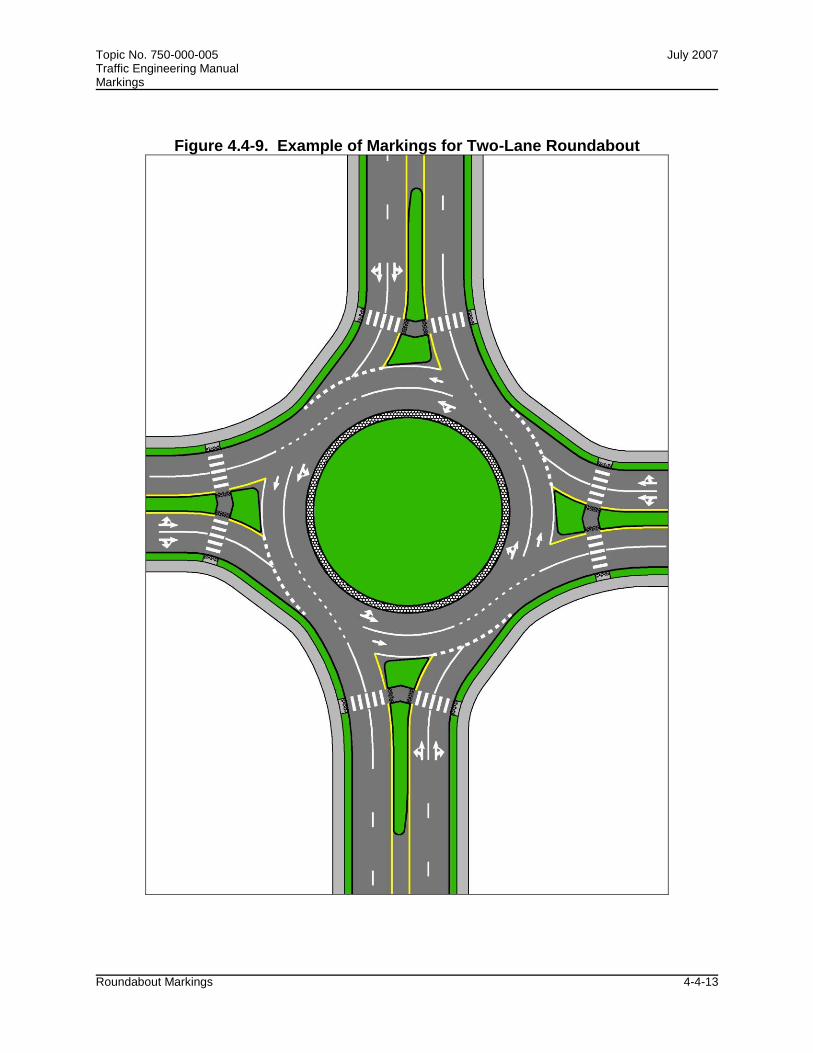
Topic No. 750-000-005 July 2007 Traffic Engineering Manual Markings
Roundabout Markings 4-4-13
Figure 4.4-9. Example of Markings for Two-Lane Roundabout

Topic No. 750-000-005 July 2007 Traffic Engineering Manual Markings
Roundabout Markings 4-4-14
Figure 4.4-10. Example of Markings for Two-Lane Roundabout with Double Left Turn

Topic No. 750-000-005 July 2007 Traffic Engineering Manual Markings
Roundabout Markings 4-4-15
Figure 4.4-11. Example of Markings for Two-Lane Roundabout with Double Right Turn

Topic No. 750-000-005 July 2007 Traffic Engineering Manual Markings
Roundabout Markings 4-4-16
Figure 4.4-12. Example of Markings for Two-Lane Roundabout with Consecutive Double Lefts

Topic No. 750-000-005 July 2007 Traffic Engineering Manual Markings
Roundabout Markings 4-4-17
Figure 4.4-13. Example of Markings for Three-Lane Roundabout with Two- and Three-Lane Approaches

Topic No. 750-000-005 July 2007 Traffic Engineering Manual Markings
Roundabout Markings 4-4-18
Figure 4.4-14. Example of Markings for Three-Lane Roundabout with Three-Lane Approaches

Topic No. 750-000-005 July 2007 Traffic Engineering Manual Markings
Roundabout Markings 4-4-19
Figure 4.4-15. Example of Markings for Three-Lane Roundabout with Two-Lane Exits

Topic No. 750-000-005 July 2007 Traffic Engineering Manual Markings
Roundabout Markings 4-4-20
Figure 4.4-16. Example of Markings for Two Linked Roundabouts

Topic No. 750-000-005 July 2007 Traffic Engineering Manual Markings
Roundabout Markings 4-4-21
Figure 4.4-17. Example of Markings for Diamond Interchange with Two Circular-Shaped Roundabout Ramp Terminals

Chapter 5
TRAFFIC OPTIMIZATION

Chapter 6
SAFE MOBILITY FOR LIFE PROGRAM

Chapter 7
TECHNOLOGY

Topic No. 750-000-005 March 1999 Traffic Engineering Manual Revised: March 2011 Certification and Approval of Traffic Control Signals and Devices
Approved Product List Certification and Approval Process 7-1-1
Section 7.1
APPROVED PRODUCT LIST CERTIFICATION AND APPROVAL PROCESS
7.1.1 PURPOSE The Department is required by federal and state law to ensure that only a safe and uniform traffic control system is implemented on streets and highways of the state. The Traffic Engineering Research Laboratory (TERL) within the Department’s State Traffic Engineering and Operations Office supports this mandate by conducting evaluation and approval of official traffic control signals and devices, and related ancillary or system equipment, proposed for use on the streets and highways of Florida. The objective of this section is to communicate the Department’s Approved Product List (APL) Product Certification and Approval Process to product suppliers and end-users. Rules and procedures for granting, maintaining, extending, suspending and withdrawing certification are also included.
7.1.2 AUTHORITY Sections 20.23(4)(a), 316.0745, 316.0747, 334.048(3), Florida Statutes (F.S.)
7.1.3 DEFINITIONS Ancillary Device: A device that facilitates the remote control or operation of traffic control devices or otherwise affects the movement of traffic on state roads. Approved Product: An ancillary device or system equipment for which the Department requires preapproval and listing on the APL and that meets or exceeds the Department’s Minimum Specifications for Traffic Control Signals and Devices (MSTCSD)or Standard Specifications for Road and Bridge Construction (SSRBC). Approved Products List (APL): A listing of approved traffic control signals and devices, and ancillary devices or system equipment that the Department has reviewed for compliance to specifications and authorized for use on the streets and highways of Florida. Certified Product: An official traffic control signal or device that complies with the MUTCD, and also meets or exceeds the MSTCSD or SSRBC . Corrective Action: An action taken to eliminate the causes of an existing

Topic No. 750-000-005 March 1999 Traffic Engineering Manual Revised: March 2011 Certification and Approval of Traffic Control Signals and Devices
Approved Product List Certification and Approval Process 7-1-2
nonconformity, defect or other undesirable situation, to prevent recurrence. Maintaining Agency: The County, City, or other authorized governmental agency in Florida that has operational and/or maintenance responsibility for the traffic control signals or devices on a given roadway. If the traffic control signals or devices are on a state road, this is the agency that has an executed maintenance agreement with the Department. Minimum Specifications for Traffic Control Signals and Devices (MSTCSD): The minimum specifications used for the evaluation, certification, and approval of official traffic control signals and devices and ancillary devices for use on the streets and highways of Florida. Nonconformity: Deviation from specified requirements related to the product or to the Department’s certification/approval requirements. Field Evaluation Plan: A document used prior to and during a Temporary Permit to plan and guide the operational field evaluation of a product. (See Section 7.1.6 for more details) Official Traffic Control Signal or Device: Any signal or device, manually, electrically or mechanically operated by which traffic is alternately directed to stop and permitted to proceed or controlled in any manner. Traffic control signals and devices regulate, warn, or guide traffic on, over, or adjacent to a street, highway, pedestrian facility, or bikeway by authority of a public agency having jurisdiction. The Department lists all specifications for traffic control signals and devices required to be preapproved and listed on the APL at: http://www.dot.state.fl.us/trafficoperations/Traf_Sys/terl/apl4.shtm Product Certification/Approval System: Procedures and management for carrying out third-party product conformity assessment. Supplier: Manufacturer or vendor of official traffic control signal or device or ancillary device. Also entity responsible for ensuring its Quality Management System (QMS) and products meet or continue to meet the Department’s standards. Surveillance: Systematic iteration of conformity assessment activities as a basis for maintaining the validity of the statement of conformity. Temporary Permit: The Department is authorized to permit traffic control signals and devices not in conformity with the uniform system upon showing of good cause. This permit is issued by the State Traffic Engineering and Operations Office for a specified time period at specific locations for a specific product. This permit is issued only when it

Topic No. 750-000-005 March 1999 Traffic Engineering Manual Revised: March 2011 Certification and Approval of Traffic Control Signals and Devices
Approved Product List Certification and Approval Process 7-1-3
has been determined to be in the best interest of the public to allow its limited use. This permit is issued to a public or private entity for the purpose of evaluating the device’s operational effectiveness and safety. (See Section 7.1.6 for more details.) Traffic Monitoring System Equipment: Any device or equipment used primarily by the Department for monitoring the volume, speed, number of axles; weight of wheels, axles or vehicles; and/or vehicular axle classification types. Traffic Monitoring System equipment is listed on the APL. The Department’s Planning Office manages the approval process for Traffic Monitoring System Equipment.
7.1.4 GRANTING CERTIFICATION OR APPROVAL All official traffic control signals and devices, and ancillary devices or system equipment shall be evaluated by the TERL and approved by the State Traffic Operations Engineer.
(1) Step 1: Request for Product Consideration (RFPC): To begin the approval
process, the manufacturer must submit an RFPC Application. The information provided will be reviewed to determine whether the product has benefit to the state of Florida and what, if any, approval process must be followed. The manufacturer will be instructed how to proceed.
(2) Step 2: Vendor Qualification: A completed Qualified Vendor List (QVL)
Application shall be submitted by the manufacturer of the product intended to be listed on the APL. All manufacturers are required to be listed as qualified before a device can be evaluated. Once qualified, the manufacturer will be instructed to proceed to Step 3a. Refer to Section 7.2 for more information regarding Vendor Qualification.
(3) Step 3a: Approved Product List (APL) Application: A completed APL
Application shall be submitted by the manufacturer of the product intended to be listed on the APL. All required attachments as noted in the application must be provided with the application, including independent lab reports. Once the application has been approved the manufacturer will be instructed to proceed to Step 3b.
(4) Step 3b: Product Evaluation and Certification/Approval: Once Steps 1
through 3a have been successfully completed the manufacturer will be notified to send the device to the TERL for evaluation. The device shall be a production unit and shall be submitted with all accessory components necessary to power-up and fully operate the device. All costs of freight and shipping shall be at the applicant's expense.
(5) The APL Application will then be fully reviewed by the evaluator for content and
the product evaluated against established specifications. If the device fails the

Topic No. 750-000-005 March 1999 Traffic Engineering Manual Revised: March 2011 Certification and Approval of Traffic Control Signals and Devices
Approved Product List Certification and Approval Process 7-1-4
evaluation or is found to have numerous or serious specification violations, the device may not be re-submitted for up to ninety days from the date of notification of such failure.
(6) Upon a successful evaluation, a recommendation will be made to the State
Traffic Operations Engineer to approve the device. If the State Traffic Operations Engineer concurs, a certification/approval letter including a certification/approval number will be provided to the manufacturer and the device will be listed on the APL at: http://www3.dot.state.fl.us/trafficcontrolproducts. Specific conditions that may apply to the certification/approval will be detailed in the letter.
(7) All approved devices and submitted documentation will be retained by the Department for as long as the device is listed on the APL.
7.1.5 TEMPORARY PERMIT PROCESS It is the intent of the Department that every effort shall be made to improve the quality and effectiveness of Florida’s streets and highways through a structured process of reviews and evaluation of new technology as it becomes available. The Department may consider if good cause exists to permit a traffic control device not in conformance with the uniform system. The temporary permit process is as follows:
(1) Step 1: Request for Product Consideration (RFPC): To begin the approval
process, the manufacturer must submit a RFPC Application. The information provided with the application will be reviewed in order to determine whether the product has benefit to the Department and whether it must be evaluated and listed on the APL. The product must have a Florida governmental sponsor (i.e., District, County, City, etc.) to proceed. The manufacturer will be instructed to proceed to Step 2 if such action is deemed appropriate by the Department.
Note: At this point the manufacturer must begin the process to become qualified. For non-standard product, the manufacturer qualification and product evaluation processes can occur concurrently. In all cases, no product can be listed on the APL unless the manufacturer has been qualified prior to listing. Refer to Section 7.2 for more information on this requirement.
(2) Step 2: Field Evaluation Plan: The device shall be submitted for review. If the Department determines that a field evaluation is needed, the submitting entity shall develop a Field Evaluation Plan and submit the plan for review. The Field Evaluation Plan shall include, at a minimum: (a) Project location and description; (b) Design requirements and criteria; (c) Operational and maintenance requirements;

Topic No. 750-000-005 March 1999 Traffic Engineering Manual Revised: March 2011 Certification and Approval of Traffic Control Signals and Devices
Approved Product List Certification and Approval Process 7-1-5
(d) Evaluation criteria, methods and responsibilities; (e) Monitoring team; and (f) Schedule with milestone events.
(3) Step 3: Temporary Permit Issuance: A monitoring team shall be formed to monitor the evaluation activity. The team shall consist of the District Traffic Operations Engineer or designee, a representative from each maintaining agency involved, a State Traffic Engineering and Operations Office representative, and a representative from the manufacturer.
(4) Once Steps 1 through 3 above has been successfully completed and the Field Evaluation Plan has been approved, the submitting entity shall receive a Temporary Permit. This permit allows the installation and operation of the device consistent with the approved field evaluation plan and any conditions outlined in the Temporary Permit letter.
(5) Step 4: Field Evaluation Conclusion: After the field evaluation is complete, the submitting entity shall prepare and submit to the State Traffic Engineering and Operations Office a final evaluation report. This report shall include, at a minimum:
(a) Summary of the operational and field results of the evaluation;
(b) Input from the Maintaining Agency as to the maintainability and reliability of the product;
(c) Responses from motorists and pedestrians concerning the effectiveness of the device; and
(d) Conclusion on the effectiveness and safety of the device.
(6) The State Traffic Operations Engineer or designee will review all operational and technical data from the evaluation as well as input from the Maintaining Agency(s), and will approve or disapprove the device. If the device is approved, specifications may be developed and the device will be placed on the APL. If the device fails the evaluation, it may be required to be removed from the field.
7.1.6 MAINTAINING APL CERTIFICATION OR APPROVAL
Maintaining certification or approval is accomplished via a surveillance program including supplier requalification and any or all of the following: (1) Successful re-evaluations of APL listed devices. The supplier may be required to
pull a sample from stock and recertify to current Department specifications. All costs associated with this review shall be paid by the applicant.

Topic No. 750-000-005 March 1999 Traffic Engineering Manual Revised: March 2011 Certification and Approval of Traffic Control Signals and Devices
Approved Product List Certification and Approval Process 7-1-6
(2) Successful and prompt resolution of any required corrective actions on issues
such as (but not limited to) supplier requalification, customer service or APL listed products.
7.1.7 EXTENDING CERTIFICATION OR APPROVAL
(1) Manufacturers with product currently listed on the APL wishing to extend (add)
new products manufactured in a previously qualified facility must follow the approval process outlined in Section 7.1.4. (excluding Step 2 – Vendor Qualification). All conditions for maintaining product certification or approval defined in Section 7.1.6 shall also be met.
(2) Manufacturers with product currently listed on the APL wishing to extend (add)
new products manufactured in a new facility that has not been qualified must follow the approval process outlined in Section 7.1.4. All conditions for maintaining product certification or approval defined in Section 7.1.6 shall also be met.
7.1.8 SUSPENDING AND WITHDRAWING CERTIFICATION OR APPROVAL
Deficiencies in product and/or supplier performance, supplier’s QA and fabrication procedures, lack of compliance with product approval/certification requirements will be evaluated. The degree of action taken by the TERL will vary with the degree of noncompliance and the effect of the deficiency on product safety and intended use of the product. Examples of deficiencies include, but are not limited to: (a) Failure of the product to perform satisfactorily or to meet current established standards and specifications; (b) Failure of the supplier to cooperate with the ongoing surveillance program,
and; (c) Failure of the supplier to notify TERL immediately of any modification,
alteration, or obsolete nature of a listed product. The withdrawal process shall be as follows:
(1) 1st Action – Corrective Action A Notice of Corrective Action will be sent to the supplier to resolve the deficiency.
Under this action, product certification/approval or supplier qualification status is not affected. The supplier is given 30 calendar days to provide a Corrective Action Plan.

Topic No. 750-000-005 March 1999 Traffic Engineering Manual Revised: March 2011 Certification and Approval of Traffic Control Signals and Devices
Approved Product List Certification and Approval Process 7-1-7
(2) 2nd Action - Suspension Failure to meet the 30-day deadline may lead to suspension. Under suspension,
the product(s) is/are masked from public view making it/them ineligible for sale or installation within the state of Florida for the period of suspension. The supplier is given 30 days to provide a Corrective Action Plan and Florida sales and delivery history within the previous 180 days.
(3) 3rd Action - Revocation Failure to meet the 30-day deadline may lead to revocation. Under revocation,
the product(s) is/are removed from the APL making it/them ineligible for sale or installation within the state of Florida and supplier qualification is rescinded. The supplier will be sent a Notice of Revocation. The subject product(s) may not be re-submitted for up to one year from the date of notification of such ineligibility.

Topic No. 750-000-005 March 1999 Traffic Engineering Manual History Revised: July 2011
History 1
HISTORY
Chapter 1 Traffic Engineering Adoption Procedure
3/09 Pen and ink changes.
12/06 Pen and Ink changes.
04/05 Changed office name. Removed rule reference for Section 2.16.
08/03 Changed website address.
03/03 Changed rule incorporation reference to 14-15.015. Updated website address.
03/02 Changed website address. Also created links to references and changed office name to Traffic Operations.
10/01 Approved to have TEM available electronically on the internet/infonet only.
Section 2.1 Use of Slippery When Wet Signs
12/06 Pen and Ink changes (updated references and/or links).
03/02 Updated references to Millennium MUTCD and included links to all references.
10/99 Section 2.1.2(3), 2nd paragraph. Added, "These signs should be placed in accordance with MUTCD Table II-1 using a 10 mph deceleration factor."
06/91 Former FDOT Topic Number 750-010-018 incorporated into TEM.
Section 2.2 Overhead Street Name Signs
06/09 Clarified sign design requirements for internally illuminated overhead signs vs. standard static panel signs.
04/07 Removed references to Advance Street Name Signs (new Section 2.37). Standardized sign sizes for overhead street name signs on State Highway System.
03/02 Updated references to Millennium MUTCD and included links to all references.
05/00 Section 2.2.4(1) and (2) changed to conform with our letter height requirements shown in Table 6.3-1 in the Elder Roadway User Program Section of the TEM.
06/91 Former FDOT Topic Number 750-010-033 incorporated into TEM.

Topic No. 750-000-005 March 1999 Traffic Engineering Manual History Revised: July 2011
History 2
Section 2.3 Signs and Markings at Non-Signalized Intersections of Divided Highways and Crossroads
12/06 Pen and Ink changes (updated references and/or links).
03/02 All references in this document are now in the 2002 edition of the Design Standards.
07/00 This section updated to include the mandatory implementation plan for Divided Highways and Crossroads issued by the State Highway Engineer.
06/91 Former FDOT Topic Number 750-010-035 incorporated into TEM.
Section 2.4 Symbol Signs on the State Highway System
12/06 Pen and Ink changes (updated references and/or links).
03/02 Updated references to Millennium MUTCD and included links to all references.
06/91 Former FDOT Topic Number 750-010-026 incorporated into TEM.
Section 2.5 Destination Distance Signs at Rural Interstate and Freeway Exit Ramp Terminals
12/06 Pen and Ink changes (updated references and/or links).
06/91 Former FDOT Topic Number 750-010-024 incorporated into TEM.
Section 2.6 Bridge Signs and Markings
12/06 Pen and Ink changes (updated references and/or links).
04/02 Updated references to Millennium MUTCD and included links to all references. We also standardized lettering size for the cross road signs on overpasses.
07/93 Cross Road Name Signs on Overpasses, added that signs can be installed if requested by law enforcement or emergency rescue organizations.
06/91 Former FDOT Topic Number 750-010-034 incorporated into TEM.
Section 2.7 Place Name Signs on the State Highway System
04/05 Rescinded. Now Part IV of Rule 14-51, F.A.C., Florida's Highway Guide Sign Program.
05/02 Minor editorial changes to make current.
05/00 Editorial comments. Section 2.7.6(2) revised to add that place name signs located off state right-of-way must conform to statute.
06/91 Former FDOT Topic Number 750-010-036 incorporated into TEM.

Topic No. 750-000-005 March 1999 Traffic Engineering Manual History Revised: July 2011
History 3
Section 2.8 Move Accident Vehicles from Travel Lanes Signs
12/06 Pen and Ink changes (updated references and/or links).
06/04 Updated sign references to the 2004 Design Standards. Added optional graphic panel to limited access sign.
05/02 Updated references to Millennium MUTCD and included links to all references.
06/91 Incorporated into TEM.
Section 2.9 No Passing Zone Signs
12/06 Pen and Ink changes (updated references and/or links).
05/02 Created a link to the W14-3 sign in the new federal Standard Highway Signs.
06/91 Incorporated into TEM.
Section 2.10 Vending Machine Signs
12/06 Pen and Ink changes (updated references and/or links).
06/04 Added sign details.
06/91 Incorporated into TEM.
Section 2.11 Guidelines for Bicycle Warning Signs
12/06 Pen and Ink changes (updated references and/or links).
09/02 Updated references to the Millennium MUTCD and the 2002 Standard Highway Signs Manual.
07/00 Editorial comments. Added Section 2.11.4 to include sign design and instructions for Bicycle Sharing Road Sign. Change initiated due to Revision 5 of the MUTCD.
06/91 Incorporated into TEM.
Section 2.12 Recycling Collection Center Signs
12/06 Pen and Ink changes (updated references and/or links).
09/04 Updated sign references to the 2004 Design Standards.
09/02 Updated sign references to the 2002 Design Standards.
06/91 Incorporated into TEM.
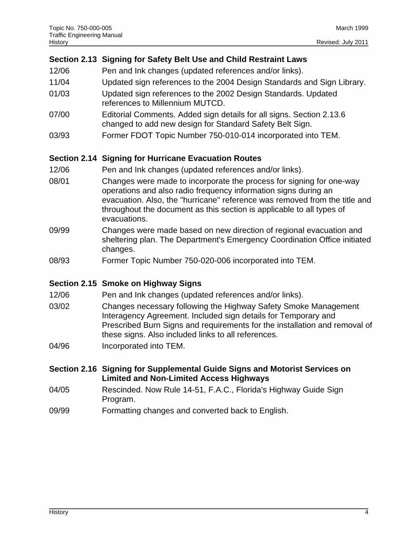
Topic No. 750-000-005 March 1999 Traffic Engineering Manual History Revised: July 2011
History 4
Section 2.13 Signing for Safety Belt Use and Child Restraint Laws
12/06 Pen and Ink changes (updated references and/or links).
11/04 Updated sign references to the 2004 Design Standards and Sign Library.
01/03 Updated sign references to the 2002 Design Standards. Updated references to Millennium MUTCD.
07/00 Editorial Comments. Added sign details for all signs. Section 2.13.6 changed to add new design for Standard Safety Belt Sign.
03/93 Former FDOT Topic Number 750-010-014 incorporated into TEM.
Section 2.14 Signing for Hurricane Evacuation Routes
12/06 Pen and Ink changes (updated references and/or links).
08/01 Changes were made to incorporate the process for signing for one-way operations and also radio frequency information signs during an evacuation. Also, the "hurricane" reference was removed from the title and throughout the document as this section is applicable to all types of evacuations.
09/99 Changes were made based on new direction of regional evacuation and sheltering plan. The Department's Emergency Coordination Office initiated changes.
08/93 Former Topic Number 750-020-006 incorporated into TEM.
Section 2.15 Smoke on Highway Signs
12/06 Pen and Ink changes (updated references and/or links).
03/02 Changes necessary following the Highway Safety Smoke Management Interagency Agreement. Included sign details for Temporary and Prescribed Burn Signs and requirements for the installation and removal of these signs. Also included links to all references.
04/96 Incorporated into TEM.
Section 2.16 Signing for Supplemental Guide Signs and Motorist Services on Limited and Non-Limited Access Highways
04/05 Rescinded. Now Rule 14-51, F.A.C., Florida's Highway Guide Sign Program.
09/99 Formatting changes and converted back to English.
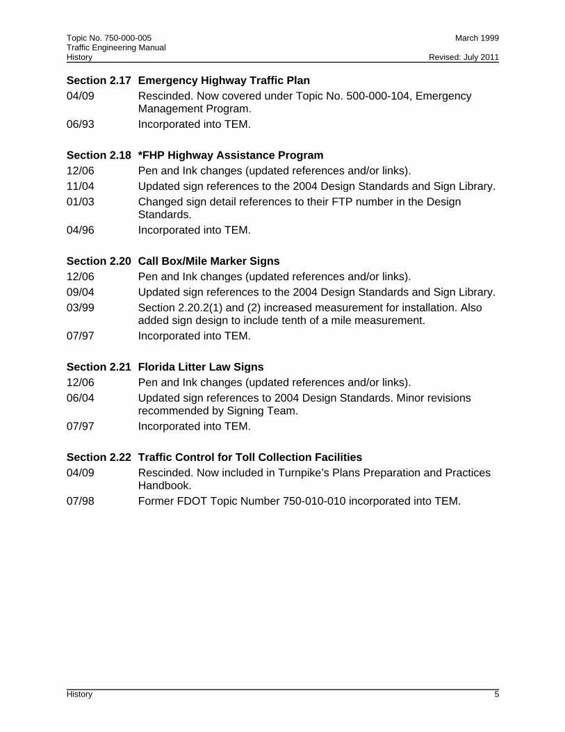
Topic No. 750-000-005 March 1999 Traffic Engineering Manual History Revised: July 2011
History 5
Section 2.17 Emergency Highway Traffic Plan
04/09 Rescinded. Now covered under Topic No. 500-000-104, Emergency Management Program.
06/93 Incorporated into TEM.
Section 2.18 *FHP Highway Assistance Program
12/06 Pen and Ink changes (updated references and/or links).
11/04 Updated sign references to the 2004 Design Standards and Sign Library.
01/03 Changed sign detail references to their FTP number in the Design Standards.
04/96 Incorporated into TEM.
Section 2.20 Call Box/Mile Marker Signs
12/06 Pen and Ink changes (updated references and/or links).
09/04 Updated sign references to the 2004 Design Standards and Sign Library.
03/99 Section 2.20.2(1) and (2) increased measurement for installation. Also added sign design to include tenth of a mile measurement.
07/97 Incorporated into TEM.
Section 2.21 Florida Litter Law Signs
12/06 Pen and Ink changes (updated references and/or links).
06/04 Updated sign references to 2004 Design Standards. Minor revisions recommended by Signing Team.
07/97 Incorporated into TEM.
Section 2.22 Traffic Control for Toll Collection Facilities
04/09 Rescinded. Now included in Turnpike’s Plans Preparation and Practices Handbook.
07/98 Former FDOT Topic Number 750-010-010 incorporated into TEM.

Topic No. 750-000-005 March 1999 Traffic Engineering Manual History Revised: July 2011
History 6
Section 2.23 Florida's Turnpike and Toll Road Numbering and Signing Program
12/06 Pen and Ink changes (updated references and/or links).
11/01 Changes made were initiated by Management to include the use of the local road name or logo (to be provided by the local expressway authority) on the toll facility along with our Toll Route Marker. Updated references to Millennium MUTCD and the sign detail for the Toll Route Marker.
04/01 Section 2.23.4(3), last sentence. Allowed possibility of local road names to be used in a guide sign or directional sign. Change initiated by management.
07/98 Incorporated into the TEM.
Section 2.24 Placement of Crime Watch Signs on the State Highway System
12/06 Pen and Ink changes (updated references and/or links).
05/04 Pen and Ink changes.
07/98 Former FDOT Instructional Memo Number 750-005 incorporated into TEM.
Section 2.25 Distance Signing for Non-Limited Access Highways
09/99 Incorporated into TEM. Implements Action Plan 006 from our Evaluation of International Signing Practices Study (1994).
Section 2.26 Advance Guide Signs on Limited Access Highways
12/06 Pen and Ink changes (updated references and/or links).
09/99 Incorporated into TEM. Implements Action Plan 007 of our Evaluation of International Signing Practices Study (1994).
Section 2.27 Commuter Assistance Signs
12/06 Pen and Ink changes (updated references and/or links).
09/99 Incorporated into TEM. Developed from discussions with Public Transportation Office.
Section 2.28 Mile-Markers on Arterial Highways
12/06 Pen and Ink changes (updated references and/or links).
04/00 Incorporated into TEM. Recommended by DTOE's during statewide meeting.
Section 2.29 Use of Fluorescent Yellow-Green Sign Sheeting
12/06 Pen and Ink changes (updated references and/or links).
07/00 Incorporated into TEM. Developed to establish guidelines for the use of this innovative sheeting that was approved by the FHWA.

Topic No. 750-000-005 March 1999 Traffic Engineering Manual History Revised: July 2011
History 7
Section 2.30 Signing for One-Stop Career Centers
12/06 Pen and Ink changes (updated references and/or links).
08/04 Updated sign references to 2004 Design Standards.
07/00 Incorporated into TEM. Developed from sign request in District Four.
Section 2.31 Unique Transportation Symbol Signs
12/06 Pen and Ink changes (updated references and/or links).
08/02 Incorporated into TEM.
Section 2.32 511 Telephone Service Sign
12/06 Pen and Ink changes (updated references and/or links).
06/04 Incorporated new FTP references.
06/02 Incorporated into TEM.
Section 2.33 Signing for Nature-based Tourism and Heritage Tourism Trails
12/06 Pen and Ink changes (updated references and/or links).
09/02 Incorporated into TEM.
Section 2.34 Signing for Florida Scenic Highways Program and the National Scenic Byways Program
12/06 Pen and Ink changes (updated references and/or links).
10/04 Incorporated into TEM.
Section 2.35 Signing for Memorial Roadway Designations
7/06 Web address for Sign Library changed.
10/04 Incorporated into TEM.
Section 2.36 Wayfinding Signs
4/07 Incorporated into TEM.
Section 2.37 Advance Street Name Signs
6/09 In order to provide consistency with the MUTCD, incorporated standards for advance street name signs not only for signalized intersections but non-signalized and the use of advance street name sign plaques for advance warning and intersection control signs.
4/07 Incorporated into TEM.

Topic No. 750-000-005 March 1999 Traffic Engineering Manual History Revised: July 2011
History 8
Section 2.38 Use of Temporary Stop Signs at Non-Functioning Signalized Intersections
5/07 Incorporated into TEM.
Section 2.39 Warning, Stop, and Yield Sign Sizes
10/07 Pen and ink changes made to table for consistency with final research report.
8/07 Incorporated into TEM.
Section 2.40 Displaying Messages on Dynamic Message Signs Permanently Mounted on the State Highway System
8/08 Incorporated into TEM.
Section 3.1 Signalized Intersections Flashing Mode Operation and Flashing Beacons
12/09 Changes made consistent with MUTCD 2003.
10/93 Page III-1 removed provision that accident patterns need to be monitored at flashing yellow/red locations. Page III-2 removed option for flashing signal operations in relation to closing times.
06/91 Former FDOT Topic Number 750-010-023 incorporated into TEM.
Section 3.2 Guidelines for Left Turn Treatment
12/09 Changes made as recommended by DTOEs, figures added.
08/93 Under Left Turn Signal Phasing, changed left turn separation from 10 to 12 feet.
06/91 Incorporated into TEM.
Section 3.3 Scheduling Traffic Signal Studies and Funding Arrangements
10/93 Former FDOT Topic Number 750-010-001 incorporated into TEM.
Section 3.4 Emergency Traffic Control Signals
02/10 Added appropriate MUTCD 2003 signs and references.
04/96 Former FDOT Topic Number 750-020-004 incorporated into TEM.
Section 3.5 Traffic Signal Mast Arm Support Boundaries
02/10 Section title change, references to PPM added, direct links to pdf versions of District Boundary Maps included.
10/98 Incorporated into TEM.

Topic No. 750-000-005 March 1999 Traffic Engineering Manual History Revised: July 2011
History 9
Section 3.6 Standardization of Yellow and All-Red Intervals for Signalized Intersections
07/11 Editorial changes made to clarity the method of determining yellow clearance time.
06/10 Changes necessary to have yellow and all-red intervals consist with ITE’s Traffic Engineering Handbook.
07/05 These are guidelines so we changed Title to reflect it. Changed from "Standardization of Yellow and All-Red Intervals for Signalized Intersections."
06/02 Incorporated into TEM.
Section 3.7 Audible Pedestrian Signals
02/03 Incorporated into TEM.
Section 3.8 Mid-Block In-Roadway Lighted Pedestrian Crosswalks
01/10 Substantive changes necessary to expand crossing treatments available with appropriate criteria and selection guidance included.
06/03 Changes necessary to conform to the MUTCD 2000 standards.
02/03 Incorporated into TEM.
Section 3.9 Countdown Pedestrian Signal Applications
03/07 Changes necessary to incorporate Department’s policy on this device.
7/06 Changes necessary to give direction to districts on implementation.
04/03 Incorporated into TEM.
Section 4.1 Crosswalks in Heavy Pedestrian Concentration Areas
08/04 Incorporated latest MUTCD 2003 changes.
06/91 Former FDOT Topic Number 750-020-008 incorporated into TEM.
Section 4.2 Lane Use of Arrow and "ONLY" Pavement Markings on Intersection Approaches
06/91 Former FDOT Topic Number 750-010-020 incorporated into TEM.
Section 4.3 Use of Blue Raised Pavement Markers to Identify Fire Hydrants
07/98 Former FDOT Instructional Memorandum Number 750-004 incorporated into TEM.
Section 4.4 Roundabout Markings
7/07 Incorporated into TEM.

Topic No. 750-000-005 March 1999 Traffic Engineering Manual History Revised: July 2011
History 10
Section 5.1 Computer Models for Traffic Engineering and ITS Analysis and Design
06/91 Former FDOT Topic Number 750-030-005 incorporated into TEM.
Section 6.1 Elder Road User Program
04/07 Rescinded. Information contained in section provided on our Safe Mobility for Life Program (Topic No. 000-750-001) website.
06/98 Incorporated into TEM. Initiated by our Elder Road User Program FDOT Topic Number 000-750-001.
Section 6.2 Warning, Stop, and Yield Sign Sizes to Accommodate the Elder Roadway User in Florida
08/07 Rescinded. Information contained in Section 2.39 (Warning, Stop, and Yield Sign Sizes).
06/98 Incorporated into TEM. Based on research developed from our Elder Road User Program.
Section 6.3 Intersection Guide Signs
04/07 Rescinded. Information contained in Section 2.37 (Advance Street Name Signs).
06/98 Incorporated into TEM. Based on research developed from our Elder Road User Program.
Section 7.1 Certification and Approval of Traffic Control Signals and Devices
03/11 Title changed and APL Vendor Qualification Program was added. Changes made to the Product Approval Process, Temporary Permit Process and APL Review Process. Moved remaining APL procedures from our MSTCSD specifications to this section.
03/99 Former FDOT Topic Number 750-010-013 incorporated into TEM.

Topic No. 750-000-005 March 1999 Traffic Engineering Manual Index Revised: December 2009
Index 1
INDEX
Statutes, Rules and Procedures pertaining to Traffic Engineering
A.1.1 STATUTES
Chapter 20 Organizational Structure
20.23 Department of Transportation
Chapter 258 State Parks and Preserves
258.007 Powers of division
Chapter 267 Historical Resources
267.062 Naming of state buildings and other facilities
Chapter 288 Commercial Development and Capital Improvements
288.1222 Definitions
Chapter 316 State Uniform Traffic Control
316.002 Purpose
316.003 Definitions
316.006 Jurisdiction
316.007 Provisions uniform throughout state
316.008 Powers of local authorities
316.074 Obedience to and required traffic control devices
316.0741 High-occupancy-vehicle lanes
316.0745 Uniform signals and devices
316.0747 Sale or purchase of traffic control devices by nongovernmental entities; prohibitions
316.075 Traffic control signal devices
316.0755 Pedestrian control signals
316.076 Flashing signals
316.0765 Lane direction control signals
316.077 Display of unauthorized signs, signals, or markings
316.0775 Interference with official traffic control devices or railroad signs or signals
316.078 Detour signs to be respected
316.079 Duty to yield to highway construction workers
316.0875 No-passing zones
316.088 One-way roadways and rotary traffic islands
316.089 Driving on roadways laned for traffic
316.090 Driving on divided highways
316.091 Limited access facilities; interstate highways; use restricted
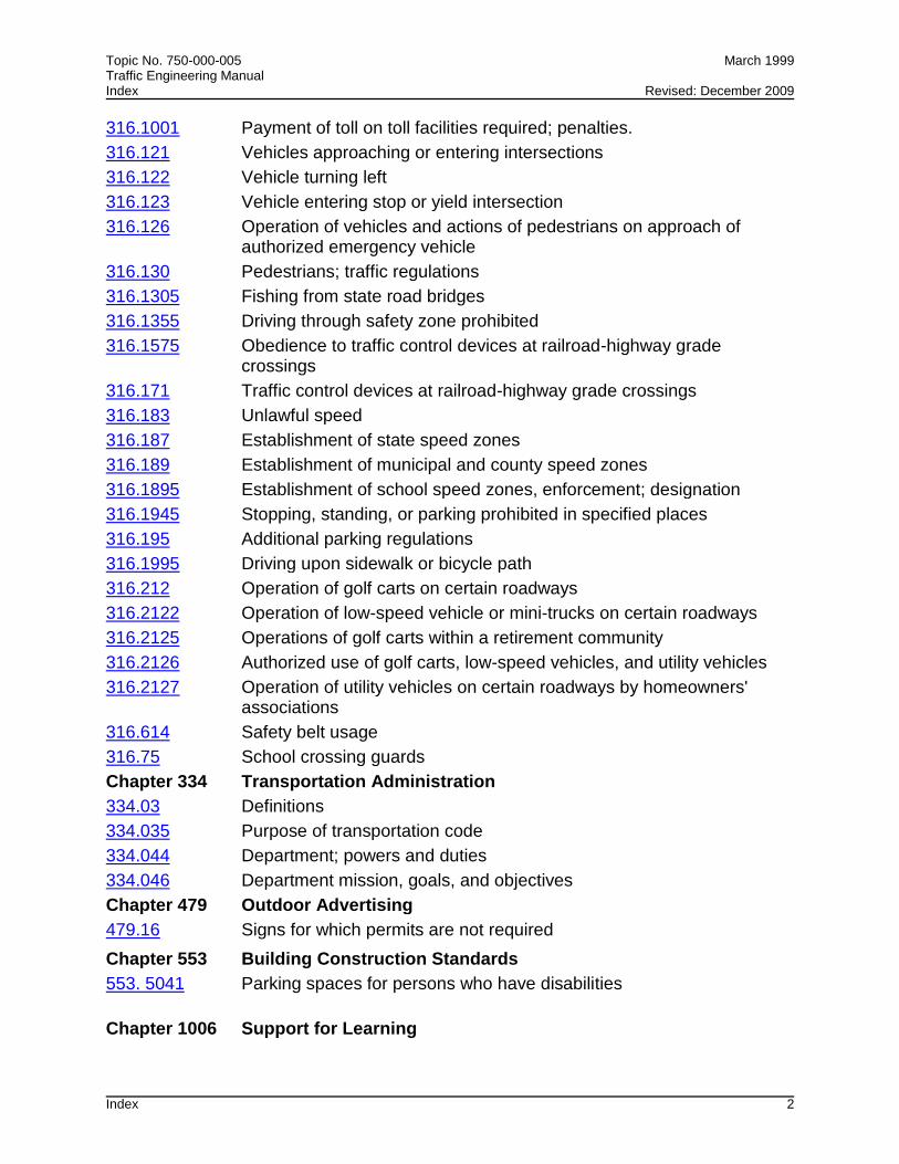
Topic No. 750-000-005 March 1999 Traffic Engineering Manual Index Revised: December 2009
Index 2
316.1001 Payment of toll on toll facilities required; penalties.
316.121 Vehicles approaching or entering intersections
316.122 Vehicle turning left
316.123 Vehicle entering stop or yield intersection
316.126 Operation of vehicles and actions of pedestrians on approach of authorized emergency vehicle
316.130 Pedestrians; traffic regulations
316.1305 Fishing from state road bridges
316.1355 Driving through safety zone prohibited
316.1575 Obedience to traffic control devices at railroad-highway grade crossings
316.171 Traffic control devices at railroad-highway grade crossings
316.183 Unlawful speed
316.187 Establishment of state speed zones
316.189 Establishment of municipal and county speed zones
316.1895 Establishment of school speed zones, enforcement; designation
316.1945 Stopping, standing, or parking prohibited in specified places
316.195 Additional parking regulations
316.1995 Driving upon sidewalk or bicycle path
316.212 Operation of golf carts on certain roadways
316.2122 Operation of low-speed vehicle or mini-trucks on certain roadways
316.2125 Operations of golf carts within a retirement community
316.2126 Authorized use of golf carts, low-speed vehicles, and utility vehicles
316.2127 Operation of utility vehicles on certain roadways by homeowners' associations
316.614 Safety belt usage
316.75 School crossing guards
Chapter 334 Transportation Administration
334.03 Definitions
334.035 Purpose of transportation code
334.044 Department; powers and duties
334.046 Department mission, goals, and objectives
Chapter 479 Outdoor Advertising
479.16 Signs for which permits are not required
Chapter 553 Building Construction Standards
553. 5041 Parking spaces for persons who have disabilities
Chapter 1006 Support for Learning

Topic No. 750-000-005 March 1999 Traffic Engineering Manual Index Revised: December 2009
Index 3
1006.21 Duties of district school superintendent and district school board regarding transportation
1006.23 Hazardous walking conditions
1006.66 Regulation of traffic at universities
Chapter 1013 Educational Facilities
1013.36 Site planning and selection
A.1.2 Active Traffic Engineering and Operations Procedures and Policy Statements
A.1.3 Rules
14-15.010 Adoption of Manual on Uniform Traffic Control Devices (MUTCD)
14-15.012 Speed Zoning for Highways Streets and Roads in Florida
14-51 Florida's Highway Guide Sign Program