traffic light system simulation - k. n. toosi university ... · h5 4 traffic light ii yellow ... an...
TRANSCRIPT

1
Traffic Light System Simulation
2
1 Control
1.1 Allocation list
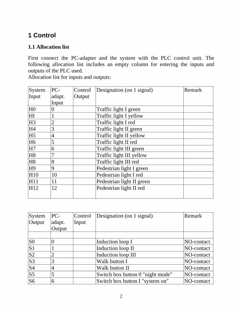
First connect the PC-adapter and the system with the PLC control unit. The following allocation list includes an empty column for entering the inputs and outputs of the PLC used. Allocation list for inputs and outputs: System Input
PC-adapt. Input
Control Output
Designation (on 1 signal) Remark
H0 0 Traffic light I green HI 1 Traffic light I yellow H3 2 Traffic light I red H4 3 Traffic light II green H5 4 Traffic light II yellow H6 5 Traffic light II red H7 6 Traffic light III green H8 7 Traffic light III yellow H8 8 Traffic light III red H9 9 Pedestrian light I green H10 10 Pedestrian light I red H11 11 Pedestrian light II green H12 12 Pedestrian light II red
System Output
PC-adapt. Output
Control Input
Designation (on 1 signal) Remark
S0 0 Induction loop I NO-contact S1 1 Induction loop II NO-contact S2 2 Induction loop III NO-contact S3 3 Walk button I NO-contact S4 4 Walk button II NO-contact S5 5 Switch box button 0 "night mode" NO-contact S6 6 Switch box button I "system on" NO-contact

3
S7 7 Switch box button II "system off NC-contact PC-
adapter Control Designation Remark
24V 24V Voltage supply (switch set to PLC) PLC, 24 V 5V 5V Voltage supply (switch set to TTL) PLC,5 V 0V 0v Device and signal ground
1.2 Sequence control
Turning on the system
The traffic-light system includes a switch box by means of which start-up can be performed. The system is turned on via NO-contact S6 and off via NC-contact S7. The activation of the system is stored by a flag. The circuit used for a storage function in the contactor control unit serves as the self-holding circuit. An NO-contact of the contactor is wired as a seal-in contact, in parallel with the "on" switch. The "off" switch consists of an NC-contact which interrupts the holding-current when operated, thus canceling the seal-in. Two types of seal-in control circuits are illustrated in the following. What is the difference between them?

4
These two circuit diagrams are to be converted into logic diagrams. As SO is an NC-contact, it must be scanned for a 1-signal. Complete the logic diagram on the right.
Of course, an RS flip-flop can also be programmed to realize a seal-in circuit. As PLC commands are always processed sequentially, the command processed last has priority. In the case of a reset priority, the switching condition for resetting the RS flip-flop must be programmed last.

5
Sequencing
The traffic-light system is a typical example of process control. If a PLC is to be used for controlling the system, a sequence is programmed. The individual steps in a sequence are always processed consecutively and in the same order. The switching condition for any step is always the preceding one.
An additional switching condition can consist of a logical operator or timer. If the traffic light system is not to be controlled in accordance with traffic situations, the switching condition is always a timer output. Sequences are always programmed in statement lists. A flag is set at the beginning of a step (e.g. Ml for step 1). A timer with a turn-on delay is started at the same time. When the timer has elapsed, the next step is commenced and the previous flag is reset. It is important for all flags to be reset when the PLC is started. The sequence could be represented in the statement list as follows:

6
After the expiry of timer 3 and, thus, the completion of step 3, step 1 can be repeated automatically.
A traffic-light system has phases of different lengths. Every phase corresponds to a step of the sequence. A step is indicated unambiguously by a flag (e.g M2 signals step 2). A flag is only set in one phase, and reset in the next phase. It is possible to specify the phases during which each individual light of the system is to be active or inactive. The switching condition for each light is the OR operation of the corresponding phase flag (step flag).
Evaluation of a positive edge:
The sequence can be commenced on the positive edge of the "system-on" flag. When specifying a positive edge, use is made of the fact that the statement list is processed cyclically. Therefore, the status of a flag need simply be compared with its status in the previous cycle. If the status in the previous cycle was 0 and is now 1, a positive edge is present.

7
1.3 Pedestrian crossing
Activate Situation: Pedestrian Crossing in the option window. Click on the DEMO mode and observe the ensuing process.
A road with a single lane in either direction is shown across the screen. A pedestrian crossing is located in the middle. Two sets of traffic lights each with three lights H0 (green), H1 (yellow) and H2 (red) are present for regulating the automobile traffic flow. The traffic lights are controlled in parallel. One set of traffic lights with the lights H9 (green) and H10 (red) is present for pedestrians. For reasons of clarity, only one set of traffic lights is shown here. In reality, there is

8
also second set, controlled in parallel. The pedestrian traffic-light unit is equipped with a switch S3 by means of which pedestrians can request a green phase. The switch box is located in the bottom, right-hand comer of the screen. It is opened with a mouse click or with the key [t]. The control keys S5 to S7 are meant for switching on the system and changing over to other operating modes, e.g. night-time operation. The traffic-light system processes 6 different phases: 1. Red phase for automobiles, red phase for pedestrians, approx. 2s 2. Red-yellow phase for automobiles, red phase for pedestrians, approx. Is 3. Green phase for automobiles, red phase for pedestrians, approx. 10s 4. Yellow phase for automobiles, red phase for pedestrians, approx. 2s 5. Red phase for automobiles, red phase for pedestrians, approx. Is 6. Red phase for automobiles, green phase for pedestrians, approx. 10s Branch to the MANUAL operating mode to run the phases manually. A pedestrian appears when switch S3 is operated. He does not cross the road while the red light H10 is on. How does the pedestrian respond if his green phase is too short? As there are six different phases, a sequence of 6 steps must be programmed. The switching statuses of the traffic lights can then be entered in a table. The switching conditions for the traffic lights can be derived directly from this table. (+ stands for OR, * stands for AND) Step Flag
Time/s Timer
H0 Gre en
H1 Yell ow
H2 Red
H9 Gre en
H10 Red
1 2 0 0 1 0 1 2 1 0 1 1 0 1 3 10 1 0 0 0 1 4 2 0 1 0 0 1 5 1 0 0 1 0 1 6 10 0 0 1 1 0 In the columns containing more 0 signals than 1 signals, the flags are scanned negatively. H0=M3 H1=M2+M4 H2=NM3*NM4 H9=M6

9
H10=NM6 The control program can now be written as a statement list. For this purpose, use the allocation list from Chapter 3.1. After the PLC has been started, a branch can be made to the EXTERNAL mode. The system is controlled via the PC-adapter inputs. The control program can now be written as a statement list. For this purpose, use the allocation list from Chapter 3.1. After the PLC has been started, a branch can be made to the EXTERNAL mode. The system is controlled via the PC-adapter inputs.
Note for Windows users:
An easy method of switching between the traffic-light system and PLC software is described in Chapter 2.6 of this manual. Can your system be activated and deactivated via the control keys in the switch box? An activation flag is set when S6 is operated. It is reset when S7 (system off) is operated. Note: Evaluate the positive edge of the activation flag to commence the sequence.
Traffic dependence
The system is not traffic-dependent yet. The green phase for pedestrians is time-controlled. If no pedestrian wants to cross the road, the green phase for automobiles (phase 3) is to remain active. At present, the control system changes automatically from phase 3 to phase 4 on the expiry of timer 3. A small change in the program is necessary here. A change from phase 3 to phase 4 should only occur if, firstly, timer 3 has elapsed and, secondly, a pedestrian request has been made. A pedestrian request (operation of S3) can be stored by a flag, just as an activation of the system. This flag is set with the key operation and must be reset by phase 4 (flag 4).
1.4 Junction
Activate Situation: Junction in the option window. Click on the DEMO mode and observe the process.

10
A main road with one lane in either direction is shown across the screen. A junction with a side road is located in the middle. The junction has a left-turning and a right-turning lane. There are separate sets of traffic lights for both lanes (H3 to H5 and H6 to H8). However, there is no point in controlling both these sets of traffic lights separately, as the right-turning and left-turning traffic have equal freedom of movement while the flow of main traffic remains interrupted. The flow of main traffic is regulated with two sets of traffic lights controlled in parallel and each having three lights HO to H2. There is a pedestrian crossing with a set of traffic lights (H11 and H12) across the side-road, and two parallel-controlled pedestrian crossings (H9 and H10) on either side across the main road. The pedestrian crossings are equipped with switches S3 and S4. Induction loops for automobile traffic (SO to S2) have also been installed. They supply a 1-signal whenever an automobile travels over them. Real traffic-dependence can be programmed with the help of these induction loops. The switch box is located in the bottom, right-hand corner of the screen. It is opened with a mouse click or with the key [t]. The control keys S5 to S7 are meant

11
for switching on the system and changing over to other operating modes, e.g. night-time operation.
Exercise: The traffic-light system is to be controlled as in the DEMO version. Traffic dependence is to be programmed additionally. The system remains in a green phase until another green phase is invoked by main traffic via induction loops or by a pedestrian. A night-time operation mode is to be programmed as well. The traffic-light system processes 10 different phases which can be entered directly into a table. Lights H6 to H8 are not present as they are connected in parallel with lights H3 to H5. The pedestrian crossings are already switched to red in phases 4 and 9, despite the continuing green phase for main traffic. This provides pedestrians with time to leave the road after the end of their green phase. 1 2 1 2 Step Flag
Time/s Timer
H0 Gre en
HI Yell ow
H2 Red
H3 Gre en
H4 Yell ow
H5 Red
H9 Gre en
H10 Red
H11 Gre en
H12 Red
1 1 0 0 1 0 0 1 0 1 0 1 2 1 0 1 1 0 0 1 0 1 0 1 3 20 1 0 0 0 0 1 0 1 1 0 4 2 1 0 0 0 0 1 0 1 0 1 5 2 0 1 0 0 0 1 0 1 0 1 6 1 0 0 1 0 0 1 0 1 0 1 7 1 0 0 1 0 1 1 0 1 0 1 8 20 0 0 1 1 0 0 1 0 0 1 9 2 0 0 1 1 0 0 0 1 0 1 10 2 0 0 1 0 1 0 0 1 0 1 A sequence of 10 steps must be programmed for the 10 different phases. The switching conditions for the traffic lights can be derived directly from the table. (+ stands for OR, * stands for AND) In the columns containing more 0 signals than 1 signals, the flags are scanned negatively. H0 = M3 + M4 H1=M2+M5
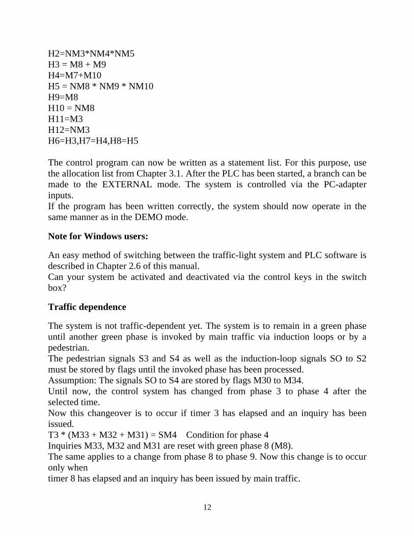
12
H2=NM3*NM4*NM5 H3 = M8 + M9 H4=M7+M10 H5 = NM8 * NM9 * NM10 H9=M8 H10 = NM8 H11=M3 H12=NM3 H6=H3,H7=H4,H8=H5 The control program can now be written as a statement list. For this purpose, use the allocation list from Chapter 3.1. After the PLC has been started, a branch can be made to the EXTERNAL mode. The system is controlled via the PC-adapter inputs. If the program has been written correctly, the system should now operate in the same manner as in the DEMO mode.
Note for Windows users:
An easy method of switching between the traffic-light system and PLC software is described in Chapter 2.6 of this manual. Can your system be activated and deactivated via the control keys in the switch box?
Traffic dependence
The system is not traffic-dependent yet. The system is to remain in a green phase until another green phase is invoked by main traffic via induction loops or by a pedestrian. The pedestrian signals S3 and S4 as well as the induction-loop signals SO to S2 must be stored by flags until the invoked phase has been processed. Assumption: The signals SO to S4 are stored by flags M30 to M34. Until now, the control system has changed from phase 3 to phase 4 after the selected time. Now this changeover is to occur if timer 3 has elapsed and an inquiry has been issued. T3 * (M33 + M32 + M31) = SM4 Condition for phase 4 Inquiries M33, M32 and M31 are reset with green phase 8 (M8). The same applies to a change from phase 8 to phase 9. Now this change is to occur only when timer 8 has elapsed and an inquiry has been issued by main traffic.
13
T8 * (M30 + M34) == SM9 Inquiries M30 and M34 are reset with green phase 3 (M3). Incorporate these changes into your statement list and test the system again. Night-time operation Control key S5 is not assigned yet. It can be used to activate a second operating mode, the night-time mode. This mode simply consists of a flashing, yellow light for automobiles meant to yield the right of way. The pedestrian traffic light remains inactive. Program another flag for night-time operation. It is set if key S5 is operated and the activation flag is inactive (locking). It is reset when S7 is operated. Also lock the activation flag against the night-time mode. Branches can now be made within the program in accordance with the two operating modes and the off state. Two additional timers are programmed for the flashing light; they are turn- on delayed and trigger each other mutually.
1.5 Crossing
Activate Situation: Crossing in the options window. Click on the DEMO mode and observe the process.
14
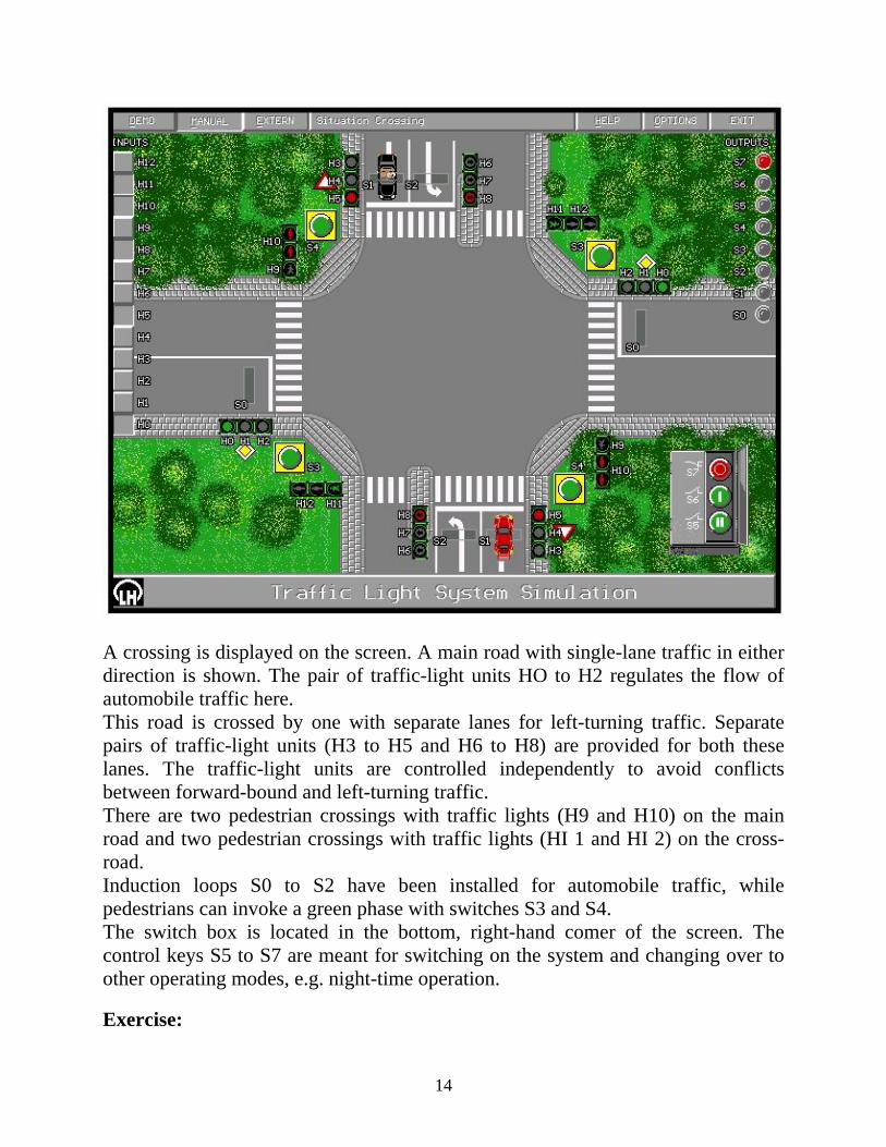
A crossing is displayed on the screen. A main road with single-lane traffic in either direction is shown. The pair of traffic-light units HO to H2 regulates the flow of automobile traffic here. This road is crossed by one with separate lanes for left-turning traffic. Separate pairs of traffic-light units (H3 to H5 and H6 to H8) are provided for both these lanes. The traffic-light units are controlled independently to avoid conflicts between forward-bound and left-turning traffic. There are two pedestrian crossings with traffic lights (H9 and H10) on the main road and two pedestrian crossings with traffic lights (HI 1 and HI 2) on the cross-road. Induction loops S0 to S2 have been installed for automobile traffic, while pedestrians can invoke a green phase with switches S3 and S4. The switch box is located in the bottom, right-hand comer of the screen. The control keys S5 to S7 are meant for switching on the system and changing over to other operating modes, e.g. night-time operation.
Exercise:
15
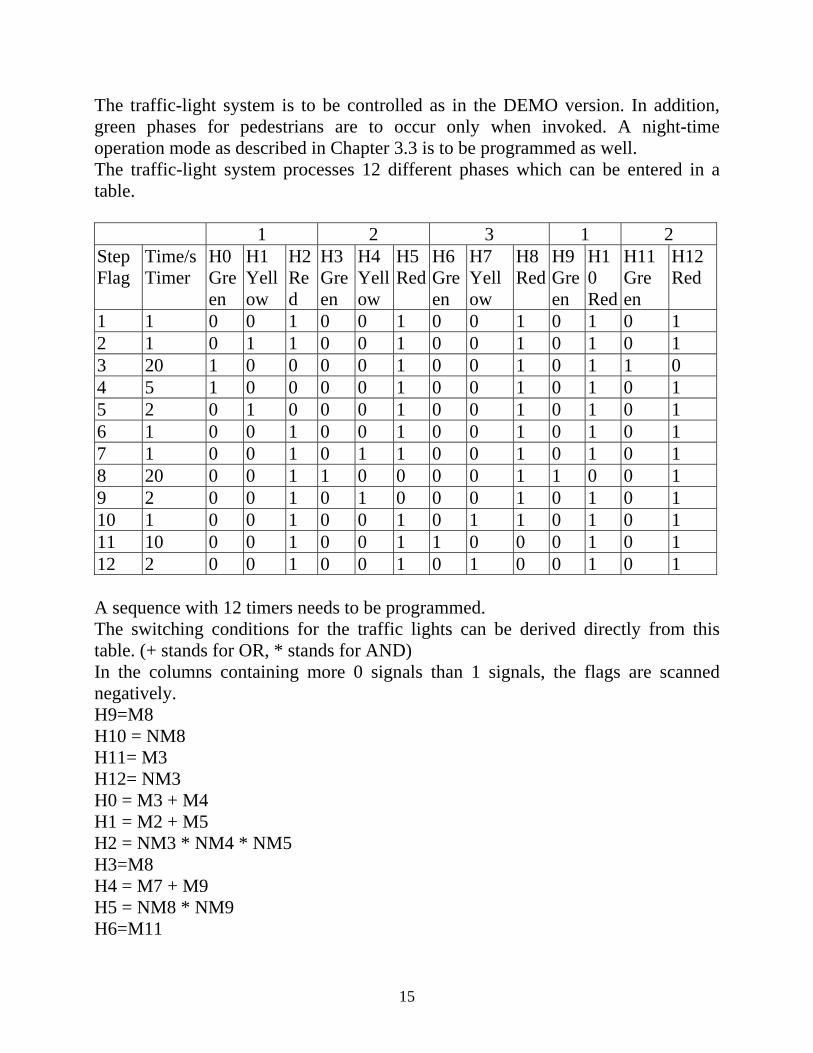
The traffic-light system is to be controlled as in the DEMO version. In addition, green phases for pedestrians are to occur only when invoked. A night-time operation mode as described in Chapter 3.3 is to be programmed as well. The traffic-light system processes 12 different phases which can be entered in a table.
1 2 3 1 2 Step Flag
Time/s Timer
H0 Gre en
H1 Yell ow
H2 Red
H3 Gre en
H4 Yell ow
H5 Red
H6 Gre en
H7 Yell ow
H8 Red
H9 Gre en
H10 Red
H11 Gre en
H12 Red
1 1 0 0 1 0 0 1 0 0 1 0 1 0 1 2 1 0 1 1 0 0 1 0 0 1 0 1 0 1 3 20 1 0 0 0 0 1 0 0 1 0 1 1 0 4 5 1 0 0 0 0 1 0 0 1 0 1 0 1 5 2 0 1 0 0 0 1 0 0 1 0 1 0 1 6 1 0 0 1 0 0 1 0 0 1 0 1 0 1 7 1 0 0 1 0 1 1 0 0 1 0 1 0 1 8 20 0 0 1 1 0 0 0 0 1 1 0 0 1 9 2 0 0 1 0 1 0 0 0 1 0 1 0 1 10 1 0 0 1 0 0 1 0 1 1 0 1 0 1 11 10 0 0 1 0 0 1 1 0 0 0 1 0 1 12 2 0 0 1 0 0 1 0 1 0 0 1 0 1 A sequence with 12 timers needs to be programmed. The switching conditions for the traffic lights can be derived directly from this table. (+ stands for OR, * stands for AND) In the columns containing more 0 signals than 1 signals, the flags are scanned negatively. H9=M8 H10 = NM8 H11= M3 H12= NM3 H0 = M3 + M4 H1 = M2 + M5 H2 = NM3 * NM4 * NM5 H3=M8 H4 = M7 + M9 H5 = NM8 * NM9 H6=M11
16
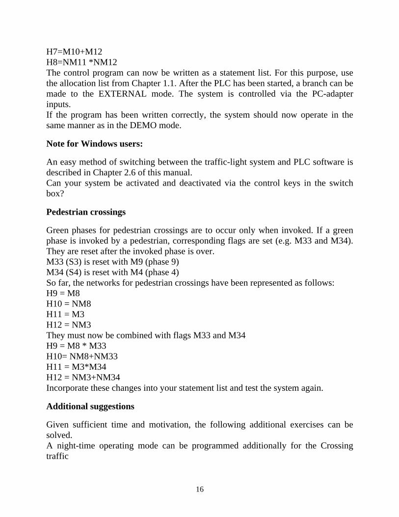
H7=M10+M12 H8=NM11 *NM12 The control program can now be written as a statement list. For this purpose, use the allocation list from Chapter 1.1. After the PLC has been started, a branch can be made to the EXTERNAL mode. The system is controlled via the PC-adapter inputs. If the program has been written correctly, the system should now operate in the same manner as in the DEMO mode.
Note for Windows users:
An easy method of switching between the traffic-light system and PLC software is described in Chapter 2.6 of this manual. Can your system be activated and deactivated via the control keys in the switch box?
Pedestrian crossings
Green phases for pedestrian crossings are to occur only when invoked. If a green phase is invoked by a pedestrian, corresponding flags are set (e.g. M33 and M34). They are reset after the invoked phase is over. M33 (S3) is reset with M9 (phase 9) M34 (S4) is reset with M4 (phase 4) So far, the networks for pedestrian crossings have been represented as follows: H9 = M8 H10 = NM8 H11 = M3 H12 = NM3 They must now be combined with flags M33 and M34 H9 = M8 * M33 H10= NM8+NM33 H11 = M3*M34 H12 = NM3+NM34 Incorporate these changes into your statement list and test the system again.
Additional suggestions
Given sufficient time and motivation, the following additional exercises can be solved. A night-time operating mode can be programmed additionally for the Crossing traffic

17
situation. A real traffic dependence can be programmed. However, it can no longer be realized with a simple sequence of steps, as a green phase can theoretically be invoked for every set of traffic lights by any induction loop or pedestrian input following a red phase. In dense traffic, however, the time-dependent sequence must be activated again to ensure smooth traffic flow.