traffic signal design and drawing preparation signal design and drawing preparation guidelines page...
TRANSCRIPT

1
Traffic Signal Design and Drawing Preparation Guidelines
July 2014
Prepared by: Traffic Engineering, Design Division, Engineering Department

Traffic Signal Design and Drawing Preparation Guidelines Page 1
Traffic Signal Design and Drawing Preparation Guidelines
JUSTIFICATION FOR IMPROVEMENTS ................................................................................................... 2
DESIGN DOCUMENTS .................................................................................................................................... 2
A. Stage 1 & Stage 2 – Preliminary Design Drawings .................................................................................................................. 2
B. Stage 3 – Final Design ................................................................................................................................................................. 2
C. Stage 4 – Construction Services ................................................................................................................................................. 2
DRAWING PREPARATION ............................................................................................................................ 3
DESIGN CRITERIA .......................................................................................................................................... 4
A. Phase Numbering Convention.................................................................................................................................................... 4
B. Traffic Signal Poles and Foundations ........................................................................................................................................ 4
C. Traffic Signal Controllers ........................................................................................................................................................... 5
D. Signal Displays............................................................................................................................................................................. 6
E. Signal Phasing and Timing ......................................................................................................................................................... 7
F. Vehicle Detection ......................................................................................................................................................................... 7
G. Traffic Signal Pullbox and Splice Box Installations ................................................................................................................. 8
H. Conduit Type, Size and Installation .......................................................................................................................................... 8
I. Traffic Signal Cable Types and Usage ...................................................................................................................................... 9
SPECIFICATIONS........................................................................................................................................... 10
TRAFFIC SIGNAL EQUIPMENT NUMBERING CONVENTION .......................................................... 11
TRAFFIC SIGNAL DETECTION NUMBERING CONVENTION .......................................................... 13
SAMPLE DRAWINGS .................................................................................................................................... 14
Sample Drawings
PRELIMINARY DESIGN SAMPLE DRAWINGS
(Stage 1 & Stage 2) Sample Mast Arm Traffic Signal Layout Plan .................................. SG001
(Stage 1 & Stage 2) Sample Span Wire Traffic Signal Layout Plan ................................. SG002
Sample Single Lane Detection Layouts ............................................................................... SG003
Sample Left Turn Lane Detection Layouts ........................................................................ SG004
Sample Multi-Lane Detection Layouts ................................................................................ SG005
FINAL DESIGN SAMPLE CONTRACT DRAWINGS
Sample Traffic Signal General Notes ................................................................................... SG006
Sample Traffic Signal Legend .............................................................................................. SG007
Sample Traffic Signal Abbreviations .................................................................................. SG008
Sample Designer’s Checklist ................................................................................................ SG009
Sample Traffic Signal Wiring Plan (Span Wire)................................................................. SG010
Sample Traffic Signal Dimension Diagram and Timing Data (Span Wire) ..................... SG011
Sample Traffic Signal Load Switch and Actuation Tables (Span Wire) ........................... SG012
Sample Traffic Signal Wiring Plan (Mast Arm) ................................................................. SG013
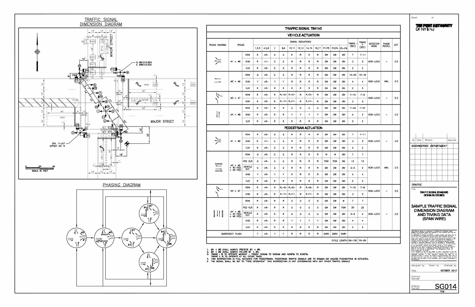
Sample Traffic Signal Dimension Diagram and Timing Data (Mast Arm) ...................... SG014
Sample Traffic Signal Load Switch and Actuation Tables (Mast Arm) ........................... SG015
Sample Traffic Signal Wiring Plan (Mid-Block Crossing) ................................................. SG016
Sample Traffic Signal Dimension Diagram and Data Tables (Mid-Block Crossing) ....... SG017
Sample Traffic Signal Removal Plan ................................................................................... SG018
Sample Modified Traffic Signal Wiring Plan ..................................................................... SG019
Sample Modified Traffic Signal Dimension Diagram and Timing Data .......................... SG020
Sample Modified Traffic Signal Load Switch and Actuation Tables ............................... SG021
FINAL RECORD SAMPLE DRAWINGS
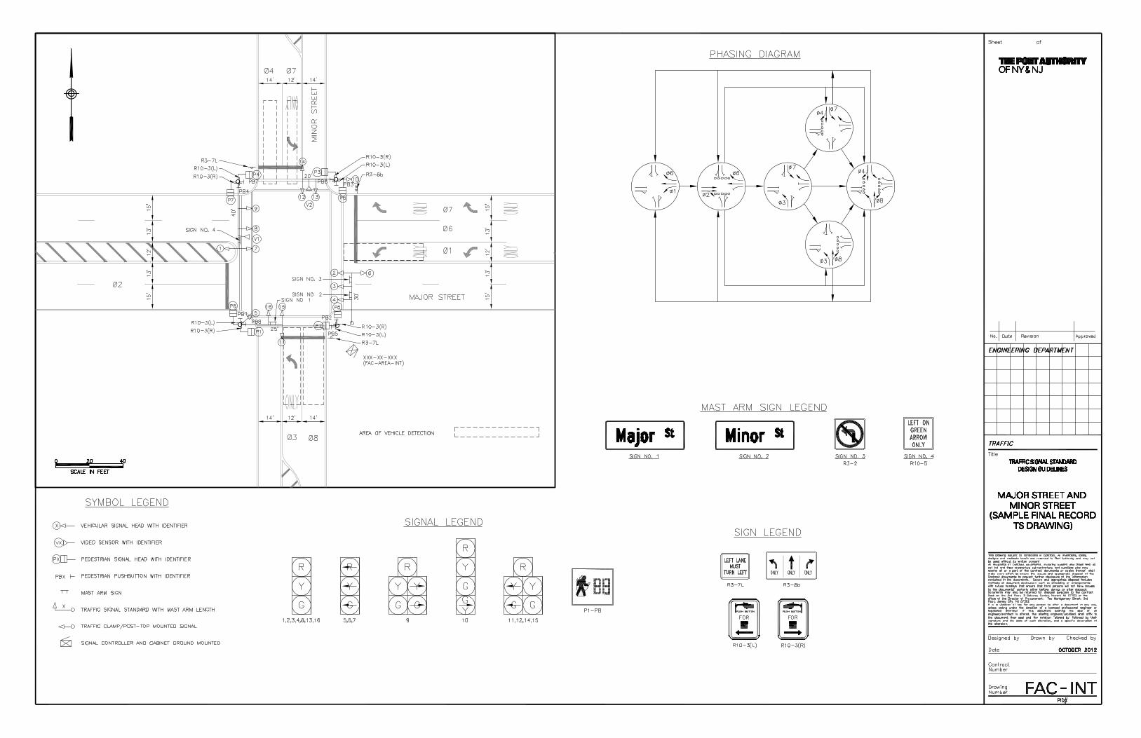
Sample Final Record TS Drawing .................................................................................. FAC-INT
Sample Final Record Traffic Signal Timing .................................................................. FAC-INT
Table of Contents

Traffic Signal Design and Drawing Preparation Guidelines Page 2
The following information is presented as a guideline for the development of typical traffic signal designs and is not intended to define all potential conditions that may be
encountered. All signal design work must be in compliance with the provisions and requirements of the current edition of the Manual on Uniform Traffic Control Devices
(MUTCD). Plans and submittals must be coordinated with Traffic Engineering.
Justification for Improvements
Before commencing the traffic signal design process, it must be determined whether improvements are warranted at the candidate location. To avoid the operational and safety issues that can result from unnecessary traffic signals, a comprehensive engineering study is required with procedures described below:
1. New traffic signals – perform an engineering study, which includes a traffic signal warrant analysis per MUTCD Chapter 4C. Obtain an authorization from the Chief Traffic Engineer prior to initiating traffic signal design.
2. Modifying existing traffic signals – prepare conceptual sketches of proposed improvements and/or modifications (including supporting documentation such as HCS, Synchro, SimTraffic, etc.) and include how they will address site-specific problems or deficiencies.
3. Removing existing traffic signals – confirm that the traffic signal is not warranted per MUTCD Chapter 4C. If none of the warrants are met, prepare a summary of findings (including support documentation) and recommendations. If one or more warrants are met, investigate and evaluate alternatives to traffic signals via engineering studies.
Additional clarification on the requirements for obtaining approvals for improvements to traffic signals is available in the document entitled, “Port Authority Intersection Signalization Procedures.” This document can be obtained from the Port Authority Traffic Engineering.
Design Documents
A. Stage 1 & Stage 2 – Preliminary Design Drawings
A Stage 1 & Stage 2 Design Level Traffic Signal Drawing is to be prepared in coordination with Traffic Engineering prior to developing the final contract documents. This plan will present the above-ground features, and should include the following:
1. Vehicular and pedestrian traffic signal layout with pushbuttons (if applicable) and signal head numbering
2. Traffic signal legend
3. Traffic signal mast arm lengths
4. Areas of vehicle detection
5. Final striping and lane usage with dimensions (for traffic signal operations only)
6. Signal phasing diagram
7. Additional features as required
8. Complete Designer’s Checklist denoting that all items have been verified (separate sheet)
See drawings SG001 and SG002 for sample traffic signal drawing formats.
B. Stage 3 – Final Design
Stage 3 Contract Documents (“SG”) Design Level Traffic Signal Drawings are to be prepared following the guidelines set forth in Drawing Preparation, Sections C & D, of this document.
C. Stage 4 – Construction Services
A Stage 4 Final Record Traffic Signal (TS) Drawing and signal timing are to be prepared and shall reflect the final field conditions to be approved by Traffic Engineering. See Intersection Number FAC-INT drawing for Sample Final Record TS drawing and Traffic Signal Timing.
General Procedures

Traffic Signal Design and Drawing Preparation Guidelines Page 3
Drawing Preparation
A. Sheet size for traffic signal drawings shall conform to the contract drawing size, which is usually 22”x34”. Drawings will be prepared using a scale of 1” = 20’ (1” = 40’ for 11”x 17” drawings). All drawings shall be prepared using the latest PANYNJ AutoCAD standards.
B. Intersections shall be orientated on the drawings with the northerly direction pointing either up or to the right. The major road must always run horizontal on the plan sheet.
C. The contract set of drawings for traffic signals shall include:
1. General Notes – “SG” drawing
2. Legends and Abbreviations – “SG” drawing
3. Sign Text Data – “T” drawing
4. Signing and Pavement Markings – “T” drawing
5. Traffic Signal Wiring Plans – “SG” drawing
6. Traffic Signal Sequence, Timing and Phasing Diagram – “SG” drawing
7. Detector Table – “SG” drawing
8. Load Switch Table – “SG” drawing
9. Standard PANYNJ details – “SG” drawing
10. Standard details from other agencies and/or jurisdictions (if applicable) – “SG” drawing
11. Details developed specifically for the project (if applicable) – “SG” drawing
D. Contract (“SG”) drawings for traffic signals shall be prepared in accordance with the most current PA traffic signal details and specifications, using the latest PANYNJ AutoCAD standards, and show the following:
1. Basemapping:
a. North arrow and bar scale
b. Street and/or ramp names
c. Curblines, handicap ramps, drop curbs and driveways
d. Sidewalks and grass buffer strips
e. Trees, shrubs and other foliage
f. Underground and overhead utility information, including pole numbers
g. Right-of-way and building lines where applicable (excluding side property lines)
h. Railroad tracks and track side features (e.g., gates, huts, etc.)
i. Bus shelters and benches
j. All existing ground-mounted and overhead signing
k. Existing traffic signals, junction boxes, controller and meter cabinets
l. Existing electrical service drop location for existing traffic signals
m. Traffic signal interconnect and communication link
n. Roadway lighting and load center
o. Striping; overall roadway width; lane widths and designations
p. Additional features as required
2. Traffic Signal Wiring Plan:
a. Vehicular and pedestrian traffic signal layout with pushbuttons (if applicable) and signal head numbering
b. Traffic signal legend
c. Foundations for signal poles, controller and meter cabinet
d. Block wiring diagram
e. Vehicle detector layout with spacing and/or zone coverage (e.g., inductance loops or video) and designation
f. Signs mounted on mast arms or span wire
g. Lateral spacing of vehicular traffic signal heads on mast arms and span wire
h. Mounting height of clamp or post-mounted traffic signals
i. Traffic signal controller and meter cabinet with electrical service drop location
j. Conduit runs, pullboxes and splice boxes
k. Location of uninterruptible power system (UPS)
l. Traffic signal interconnect and communication link
m. Striping (for traffic signal operations only)
n. Underground and overhead utilities
o. Roadway lighting
p. Additional features as required
Traffic signal wiring plans shall be designated as “SG” drawings in the contract set. See drawings SG010 – SG021 for sample traffic signal wiring plan and contract drawing formats.
Drawing Preparation

Traffic Signal Design and Drawing Preparation Guidelines Page 4
Design Criteria
A. Phase Numbering Convention Traffic movements shall follow NEMA phasing designation and convention as shown below.
See drawings SG001, SG002, and SG010 – SG021 for the typical utilization of the phase numbering convention shown above.
B. Traffic Signal Poles and Foundations 1. Verify proper lateral and vertical overhead utility clearances with all proposed traffic signal poles, mast
arms, and span wire, per the National Electrical Safety Code and other State requirements.
2. Structural loading calculations shall be prepared for traffic signal poles, foundations, and span wires to be reviewed by PANYNJ Structures and PANYNJ Geotech.
B. Steel Traffic Signal Structures
Structures shall be designed in accordance with the latest edition of the AASHTO Standard Specifications for Structural Supports for Highway Signs, Luminaires and Traffic Signals. Design in accordance with the following:
1. Design Life: 50 years
2. Minimum values to be used in Equation 3.8.3-1:
a. Basic Wind Speed: 110 mph
b. Gust Effect Factor: 1.14
c. Height and Exposure Factor, Kz: 0.94
d. Wind Importance Factor, Ir: 1.00
3. All steel traffic signals shall be designed for fatigue in accordance with the provisions described in Chapter 11 of the AASHTO Specifications. Design shall include the following equivalent static load effects: Galloping, Vortex Shedding(as applicable), Natural Wind Gust, and Truck Induced Gust. Fatigue category determination shall be as follows:
a. For structures with mast arm lengths 55’ long and longer: Fatigue Category I
b. For Structures with mast arm lengths 50’ long and shorter: Fatigue Category II
C. Aluminum Traffic Signal Structures
Structures shall be designed in accordance with the latest edition of the AASHTO Standard Specifications for Structural Supports for Highway Signs, Luminaires and Traffic Signals. Design in accordance with the following:
1. Design Life: 25 years
2. Minimum values to be used in Equation 3.8.3-1:
a. Basic Wind Speed: 110 mph
b. Gust Effect Factor: 1.14
c. Height and Exposure Factor, Kz: 0.94
d. Wind Importance Factor, Ir: 0.77
3. Fatigue shall be waived.
The Consultant shall analyze the aluminum signal structure with the proposed attachments and shall compute and verify the top of foundation (i.e. bottom of structure) loads against the loads provided in the standard drawings. The Consultant shall use the computed loads or the loads shown in the standard drawing (whichever controls) for designing the foundations and anchor bolts and show them in the contract plans. For uniformity of appearance and inventory every effort shall be made to use the signal dimensions and sizes as shown on the standard details. The standard details describe a minimum design load configuration. For comparison purposes, a worksheet is available to assess the magnitude of load effects on proposed structures against the load effects generated by the configuration described in the standard
Design Criteria

Traffic Signal Design and Drawing Preparation Guidelines Page 5
details. The worksheet provides a qualitative comparison only and is not intended as a substitution for design.
4. For designs using poles and mast arms, both types of materials (i.e., steel and aluminum) are acceptable within the same installation.
a. Mast arm lengths shall range from a minimum of 15 feet up to a maximum of 65 feet, measured in five foot increments. Aluminum mast arms and poles may be used for mast arm lengths between 15 and 25 feet. Steel mast arms and poles must be used for mast arm lengths between 30 and 65 feet.
b. Steel and aluminum cantilevered traffic signal structures shall be designed and manufactured in accordance with the AASHTO Standard Specifications for Structural Supports for Highway Signs, Luminaries, and traffic Signals, 5th Edition, 2009. The Fatigue criteria for the design of aluminum cantilevered structures as presented in these AASHTO specifications is waived.
5. For traffic signal installations that will use traffic signal poles and mast arms, the following information is furnished to provide guidance in the selection of traffic signal poles and foundations at PANYNJ intersections.
a. Traffic signal pole, type “T” shall be used with foundation type “SFT”.
b. Traffic signal pole, type “K” shall be used with foundation type “SFK”.
c. Traffic signal pole, type “S” shall be used with foundation type, “STF”.
d. Traffic signal pedestal poles shall be used with foundation type, “SPF.” Standard pole height for post top mounted traffic signal heads is 12 feet. The standard pole height for pedestrian signal heads is 8 feet.
e. Vertical clearance to vehicular traffic signal heads installed over roadways shall typically range from 16’-6” to 17’-0”, as measured from the highest point of the roadway surface to the bottom of the signal head housing. Vertical clearances less than 16’-6” may be necessary due to site conditions (i.e., flight path restrictions, overhead structures, etc.); however, a minimum clearance of 15’-6” must be provided. At facilities where overheight vehicles are anticipated (such as Port Newark/Elizabeth PA Marine Terminals), all vehicular signal heads shall be mounted to provide a vertical clearance between 17’-6” and 18’-0”. The vertical clearance shall be specified on the design details. The height at which the 15’ and 20’ arms are attached to the T-pole and the 25’ arm is attached to the K-pole limits the maximum vertical clearance to 16’-6” and 17’-6” respectively when the pole is set 2’-8” from the curb. At this offset the low chord of the arm may control the vertical clearance if a greater clearance to the signal head is desired.
f. Foundations for all traffic signal poles shall be located as far as practical from the edge of the traveled way without adversely affecting the visibility of the signal indications or obstructing the passage of persons either on the sidewalk or within the access from the sidewalk to the crosswalk. At a minimum, the center for all aluminum traffic supports shall be offset 2’-8” (32”) from the curb face. Where practical, all steel poles shall be located out of the clear zone (refer to the American Association of State Highway and Transportation Officials (AASHTO) Roadside Design Guide). The use of traffic barriers may be considered based on field conditions, where poles cannot be
located outside of the clear zone. All steel traffic signal supports shall be offset a minimum of 10’ from the curb face. In addition, reference should be made to the Americans with Disabilities Act Accessibility Guidelines for Buildings and Facilities (ADAAG) and Public Rights-of-Way Accessibility Guidelines (PROWAG) to ensure that the proper clearance is met for all passage areas around any signal pole base.
g. Soils testing and structural calculations are required for all foundations installed in accordance with the PANYNJ Geotech procedure, and must be signed by a structural engineer and reviewed by PA Structures and PA Geotech.
6. Pole and mast arm finishes will be dictated by the facility on a case-by-case basis.
7. Spare equipment including poles, mast arms and hardware will be dictated by the facility on a case-by-case basis.
8. For traffic signal installation applications that will use poles and span wire, the following information is furnished to provide guidance for the selection and design at PANYNJ intersections.
a. In order to provide reserve capacity to support the installation of additional signal equipment in the future, all span poles and foundations shall be designed to support 125% of the signal loads that are shown on the plans.
b. Span pole height shall be calculated utilizing the following criteria:
(i) Minimum vertical clearance shall be as stated in Design Criteria Section B.4.e.
(ii) Height of signal heads being installed.
(iii) One foot allowance for a signal hanger bracket.
(iv) Span wire sag equal to 5% of span length shall be provided.
(v) 18 inch allowance for the distance between the top of the span pole and the span wire attachment point.
(vi) Existing intersection grades must be evaluated prior to selection of span pole height.
(vii) The pole height shall be specified in even two-foot increments, and shall be the sum of the above values rounded up to the next two-foot increment to provide for future signal requirements.
(viii) The designer shall specify the height of pole, design load capacity of the poles, footing capacity, and footing width on the design details.
C. Traffic Signal Controllers
The Port Authority standard controller is the Eagle Siemens EPAC NEMA TS-2/Type 2, in compliance with NTCIP standards, or approved equal. The controller shall be capable of transmitting and receiving all of the NTCIP functions to and from the PA Traffic Signal Management System.
Design Criteria

Traffic Signal Design and Drawing Preparation Guidelines Page 6
The location of the traffic signal controller should be based on the following criteria:
• Offset the controller as far away from the travelled way as practical. • Location should reduce vulnerability to vehicular crashes. • Location should not restrict sidewalk accessibility. • Door on cabinet should open away from traffic to provide the controller maintenance personnel
optimal visibility of the signal indications. • Consider elevating the critical electrical components above the flood elevation.
D. Signal Displays
Polycarbonate signal heads are preferred except where aluminum signals are required, such as for post top-mounted signals and end-mount free-swinging signals. The material type for all sections shall be specified on the contract drawings. Upper tether wires are required for all span wire installations. The minimum requirements set forth in the MUTCD shall be met.
1. Vehicular Signals:
a. 12 inch signal sections are required for all vehicular signals, in accordance with the MUTCD.
b. All signal sections shall be LED-type.
c. It is recommended that two vehicular traffic signal faces be provided for the primary far-side indication for each intersection approach. A near-side vehicular traffic signal face should be provided for stop bar definition, unless geometric or other site constraints exist that precludes its installation. Mast arm traffic signals should have a “near left” / “far right” orientation where practical.
d. The use of supplemental signal faces should be considered to improve signal visibility where geometric conditions limit visibility. If required, supplemental signal faces should be clamp or post-top-mounted 12 feet above finished roadway grade, unless site conditions dictate a different mounting height. Post top-mounted signals shall not have more than 3 signal sections. Signal faces with 4 signal sections and above shall be clamp mounted on the appropriate traffic signal support.
e. Span wire signals shall utilize a separate yellow and green arrow signal section arranged in a “doghouse” configuration next to the yellow and green ball when the phasing dictates protected/permissive turning movements. For overhead mast arm installations, the preference is a “doghouse” signal; however a 4-section bi-modal arrow signal may be used.
f. In areas with overhead sign structures, the signal faces should be designed such that they are not obstructed from the view of approaching vehicles by the structure.
g. Backplates shall be installed on signal faces to improve signal visibility where conditions present visual distractions (due to sun glare, lighting, signs, buildings, etc.).
2. Pedestrian Signals and Pushbuttons:
a. The use of pedestrian signal heads shall be determined on a site by site basis, according to guidance provided in the MUTCD.
b. Pedestrian signal faces shall be LED units that display a solid Walking Person and Upraised Hand symbols in accordance with the symbol designs that are set forth in the Standard Highway Signs and Markings Book and the MUTCD. Symbol height shall be 11 inches.
c. The use of pedestrian interval countdown displays shall be standard for all traffic signal designs. Any accessible pedestrian signals and detectors (e.g., audible tones, tactile arrows, vibrotactile devices, speech messages, etc.) may be considered if appropriate. If used, the requirements of MUTCD Chapter 4E shall apply.
d. Pedestrian signal faces should be mounted eight feet above the sidewalk elevation. If site conditions warrant, pedestrian signals may be mounted to a maximum of 10 feet above the sidewalk elevation to improve visibility.
e. Pedestrian pushbuttons shall be utilized based upon the following signal operational criteria:
(i) Semi-Actuated Traffic Signals
(a) Pushbuttons should be provided to actuate the pedestrian phases associated with minor street approaches equipped with vehicle detectors.
(b) Pushbuttons are not required on the major street. The major street will operate with pedestrian recall.
(ii) Fully-Actuated Traffic Signals
(a) Pushbuttons should be provided on all approaches. (b) Pedestrian recall will not be provided in the signal operation.
(iii)Fixed Time (Pre-Timed) Traffic Signals
(a) No pushbuttons are needed. (b) Pedestrian recall should be provided for the major and minor streets.
f. Where pedestrian signals are provided, pedestrian pushbuttons shall include signs (R10-3) with appropriate arrow indication [L or R] for crossing path mounted above the pedestrian pushbuttons. Other signs may be used if found to be more appropriate for the specific location.
g. Where pedestrian signals are not provided, but pedestrian pushbuttons are used, signs (R10-4) shall be provided. The pushbuttons shall provide the minimum green time for a pedestrian crossing, in accordance with the current MUTCD.
h. Pushbuttons must be of the LED latching type.
i. Pedestrian pushbuttons should be capable of easy activation and conveniently located near each end of the crosswalk (per the MUTCD). Pushbuttons shall be placed between 1.5 feet and 6 feet from the curb face and should be no further than 10 feet from the curb face where physical constraints exist. As the pushbuttons must be accessible and installed in accordance with the ADAAG/ PROWAG reach ranges, extension of the sidewalk may be necessary to accommodate these requirements.
Design Criteria

Traffic Signal Design and Drawing Preparation Guidelines Page 7
3. Visors and Louvers
a. Vehicular signal sections should be installed with open tunnel visors.
b. Where adjacent approaches to an intersection join at an angle of 60 degrees or less, the use of geometrically programmed louvers, angle visors, programmable traffic signal heads or other visibility limiting techniques should be considered. To avoid swinging, which may affect visibility, the designer should consider fix-mounting these signal heads.
E. Signal Phasing and Timing 1. When determining the number of signal phases and the use of protected versus protected/permitted left
turn phases, the designer shall consider safety, capacity, geometric and traffic conditions. The use of protected and protected/permitted left turns shall be evaluated on a case-by-case basis. Traffic Engineering shall make the final determination.
2. Signal timing values shall be developed based on an operational analysis of the intersection.
3. Yellow and All–Red times shall be calculated based on the latest edition of the PA Standard Procedures, utilizing the latest version of the PA Traffic Signal Yellow Change and Red Clearance Intervals Worksheet.
4. Pedestrian “Walk” and flashing “Don’t Walk” times shall be calculated in accordance with the latest edition of the PA Pedestrian Intervals Worksheet.
5. The criteria for coordinated signals shall consider:
a. Improving throughput capacity along a roadway corridor.
b. Controlling queues at closely spaced intersections.
6. The phasing of the intersection should be such that any potential of a yellow-trap situation is eliminated.
7. The following information is to be provided as part of the signal timing:
a. Minimum Green time (initial): seven seconds minimum for turn slots and side street through movements; 15 seconds minimum for main street through movement.
b. Maximum Green time.
c. Yellow time.
d. All Red time.
e. Vehicle Extension (typically 2 sec.) for actuated phases.
f. Pedestrian “Walk” and flashing “Don’t Walk” time for each pedestrian phase.
g. Timing plan number.
h. Cycle.
i. System offsets and reference point (for coordinated traffic signal systems only).
j. Time of day schedule.
k. When designing a traffic signal within the vicinity of an at-grade railroad (RR) crossing, it must be investigated whether RR pre-emption will be incorporated into the signal operation. Intersection and queuing analyses must be performed to determine if vehicles stopped at a red signal will queue onto the RR tracks. A pre-signal shall be utilized to prevent vehicles from queuing on RR tracks.
8. The new controller shall be compatible with the PA Centralized Traffic Signal Management System.
See drawings SG011, SG014, SG017, SG020, and FAC-INT for sample signal timing formats.
F. Vehicle Detection
Detection shall be designed in accordance with the latest edition of the Institute of Transportation Engineers publication, Traffic Detector Handbook. Video detection is preferred if the following criteria can be met. Inductance loops or another technology may be considered based on existing or proposed conditions and deemed acceptable by Traffic Engineering.
1. Video Detection:
The following guidelines shall apply:
a. The video detection zone shall be centered in the respective lane(s) or approach to a multilane roadway.
b. See drawings SG003, SG004 and SG005 for video detection sample layouts, spacing, offsets and numbering convention.
c. The designer shall complete the intersection actuation table; see drawings SG012, SG015, and SG021 for sample format.
d. The placement of the video sensor for the respective areas of detection should be such that there is a clear and unobstructed view of the area so that any false calls are avoided. Installation must be in accordance with PA details.
e. The video sensor cable (VSC) for video detection shall run continuously from the camera to the detector card in the controller without splicing.
f. For any installation that will utilize video detection, a fully functional video detection system shall be provided and installed in the controller cabinet, including a mouse and a video monitor unit.
2. Inductance Loops:
The following guidelines shall apply:
a. Inductance loop detectors shall be designed using the following offsets:
(i) For lanes that are 12 feet or greater: 3 feet from face of curb or edge of roadway and 3 feet from adjacent lane.
(ii) For lanes that are 11 feet: 3 feet from face of curb or edge of roadway and 3 feet from adjacent lane.
Design Criteria

Traffic Signal Design and Drawing Preparation Guidelines Page 8
(iii) For thorough / right lanes less than 10 feet: 2 feet from face of curb or edge of roadway and 3 feet from adjacent lane. For left turn lanes less than 10 feet: 2 feet from adjacent lane and 3 feet from opposing travel lane.
b. Inductance loops operating in presence mode shall be placed no more than 10 feet nor less than 2 feet behind the extended curbline of the intersecting roadway closest to the approach where detection is being placed.
c. If possible, do not design loops that are within one foot of any manhole, water valve or other appurtenance.
d. Calculate the appropriate inductance based on the number of turns for each loop detector as shown in drawings SG012 and SG015.
e. A separate shielded lead–in cable (with drain wire) shall be specified for each loop that is installed. Lead-in cable shall be installed as a “home run” cable (i.e., no splices) from the splice box to the control cabinet.
f. See drawings SG003, SG004 and SG005 for sample loop detector layouts, spacing, offsets and numbering convention.
g. The designer shall complete the intersection actuation table; see drawings SG012 and SG015 for sample format.
h. Only one loop should be wired to each channel of the loop amplifier.
3. Emerging Technologies:
a. Alternate technologies may be considered after video detection and inductance loops have been evaluated and deemed ineffective for the site conditions.
G. Traffic Signal Pullbox and Splice Box Installations 1. Pullboxes shall be designed to accommodate traffic signal cables, conduit, and cables for interconnect
communication.
2. Splice boxes shall be utilized for splicing inductance loop detectors to loop detector leads.
3. Pullboxes and splice boxes should be designed so that entering conduit runs are as straight as possible.
4. Pullboxes shall be used whenever there is a change in direction of the conduit runs.
5. For long conduit runs (e.g., communication and/or interconnect cable), pullboxes should be installed every 500 feet.
6. Pullboxes shall be designed and located to accommodate up to 6 conduit run terminations.
7. Pullboxes and splice boxes shall be designed using the following conditions to facilitate signal cable or loop detector installation and future signal modification:
a. Pullboxes shall be installed adjacent to signal poles and controller cabinets to provide access to these facilities.
b. Pullboxes shall be installed on each end of conduits installed under paved roadways.
c. Splice boxes shall be installed on intersection approaches that include multiple inductance loop detector installations to provide a suitable location for splicing roadway loop wires to loop lead-in cables.
H. Conduit Type, Size and Installation 1. Conduits shall be either concrete encased PVC (RNMC-C), rigid galvanized steel (RGS) or flexible steel
(FSC) and designed using the following criteria:
a. Traffic signal conduit installed underground between pullboxes shall have a minimum of two – 3” diameter PVC conduits encased in concrete. For locations where conduit fill or excessive conduit terminations is an issue, 4” diameter conduits may be used.
b. Traffic signal conduits installed between signal foundations and pullboxes shall confirm to the following:
(i) One – 4” diameter PVC conduit encased in concrete for steel and aluminum mast arm poles.
(ii) One – 3” diameter PVC conduit encased in concrete for pedestal poles.
(iii)Two – 3” diameter PVC conduit encased in concrete for span wire poles.
c. A minimum of three and a maximum of four conduits shall be installed between controller cabinets and adjacent pullboxes. Can use 3” or 4” diameter PVC conduit as required.
d. Traffic signal conduit installed above ground shall be rigid galvanized steel (RGS) to match the size of the underground conduit.
e. Interconnect and/or communication conduit shall be a minimum of 3” diameter PVC.
f. Detector conduit at curb shall be a minimum of one – 1.5” diameter FSC, installed thru-curb, and accommodate up to 3 inductance loop detectors. If more than 3 inductance loop detectors need accommodation, two – 1.5” conduits shall be installed through the curb.
g. Detector conduit between loop splice boxes and signal pull boxes shall be 1.5” diameter RGS.
h. A separate conduit shall be installed for service power. Conduit for electrical service shall be in accordance with the utility supplying electricity to the intersection and should be coordinated with PA Electrical Engineering.
i. All conduit runs crossing a road shall contain an empty conduit.
2. Conduit sizes shall be determined based on a maximum percent fill of 40%, in accordance with the latest edition of the National Electrical Code.
3. Grounding of the underground conduit system shall be in accordance with the current edition of the National Electrical Code. All grounding shall terminate at the traffic control cabinet’s grounding bus. Conduit for loop detector lead does not need grounding.
and Specifications
Design Criteria

Traffic Signal Design and Drawing Preparation Guidelines Page 9
4. Ground wire is to be installed continuous throughout the traffic signal system and secured to all ground rods, cabinets, pull boxes and traffic signal bases as noted.
5. Conduit runs should be designed to avoid field bends to the greatest extent possible.
6. A conduit run separate from those carrying voltage conductors is required for communication and/or interconnect.
See drawings SG010, SG013, SG016, and SG019 for sample formats.
I. Traffic Signal Cable Types and Usage 1. The standard conductor size for traffic signal cable applications shall be #14 AWG. Voltage drop
calculations shall be performed for the longest cable runs. In cases where the voltage drop exceeds five percent, the conductor size for traffic signal cable shall be #12 AWG. The cable shall be continuous from the base of the traffic signal support to the controller without any splices.
2. Traffic signal conductors shall be assigned in accordance with the wire color codes shown in the Master PA Specification List.
3. Cable assignments shall be shown in the block wiring diagram on the Traffic Signal Wiring drawing. The block wiring diagram shall indicate the cable letter for each cable extending from the controller to the traffic signal pole. The letters shall be assigned sequentially to cables terminating at the signal pole farthest from the control cabinet first, then the second farthest, etc. See drawings SG010, SG013, SG016, and SG019 for sample formats.
4. All wires connected to the controller shall be shown in a block wiring diagram, as depicted on drawings SG010, SG013, SG016, and SG019.
5. Vehicular and pedestrian traffic signal heads and pushbuttons shall not be wired together.
6. A separate neutral shall be provided for each phase and overlap of the vehicular signals.
7. The designer shall calculate the wire fill of all conduits to ensure conformance to the National Electrical Code. The following cable areas shall be used:
Cable Cross Sectional Area #14 AWG #12 AWG
10/C 0.322 sq. in. 0.383 sq. in. 5/C 0.166 sq. in. 0.198 sq. in. 2/C 0.105 sq. in. 0.124 sq. in.
Ground Wire # 8 AWG (Insulated) 0.056 sq. in.
Loop Detector Lead (LDL) #14 AWG 0.091 sq. in. Video Sensor Cable (VSC) 0.200 sq. in.
8. The designer shall observe the following criteria:
a. For mast arm installations, all signal indications should be wired individually on a 10/C cable.
b. For span wire installations, all signal indications should be wired individually on a 10/C cable or a 5/C cable as required. One spare 10/C cable shall be run across the entire span.
c. All pedestrian indications shall be individually wired on 5/C cable.
d. All pushbuttons shall be individually wired on a 2/C cable.
e. If the above criteria cannot be met due to existing or proposed constraints, the following may be considered:
(i) 3-Section signal heads that would never be considered in the future to be changed to 4 or 5 section heads can be wired on a 5/C cable.
(ii) Signal indications on the same phase can utilize the same cable. Signal indications for opposing phases should not be wired on the same cable.
(iii) Neutrals can be shared on signal heads of the same phase.
J. Uninterruptable Power Supply (UPS) UPS requirements vary per facility. The designer shall contact the facility electrical maintenance shop for UPS requirements for every project.
Design Criteria and Specifications

Traffic Signal Design and Drawing Preparation Guidelines Page 10
Specifications
Based on the Master PA Specification List, the designer shall select all appropriate specifications for each project, which will include all traffic signal items for all disciplines (i.e. specifications for traffic, civil, structural, and electrical). If required for non-standard items, a custom “C Spec.” must be prepared.

Traffic Signal Design and Drawing Preparation Guidelines Page 11
Traffic Signal Equipment Numbering Convention
Traffic Signal displays shall be numbered in accordance with the following convention for vehicular and pedestrian signal faces. Intersections shall be orientated on the drawings with the northerly direction pointing either up or to the right. The major road must always run horizontal on the plan sheet.
A. For main line arterials with an east-west orientation, vehicular signals shall be numbered using the priorities indicated below (as shown in Figure 1 and Figure 2). Signal faces shall be numbered from left to right on all approaches:
Priority 1: Signal indications for eastbound traffic Priority 2: Signal indications for westbound traffic Priority 3: Signal indications for northbound traffic Priority 4: Signal indications for southbound traffic
Pedestrian signal displays shall be numbered using the priorities indicated below and shall have a “P” prefix to identify them as pedestrian signals. Pedestrian Pushbuttons shall be numbered utilizing the above convention with a “PB” prefix. The face numbers shall be assigned with the same priorities as vehicle signals, and shall be numbered from left to right (from an approaching vehicle perspective) concurrent with the respective vehicle signal priorities:
Priority 1: Southerly Crosswalk Priority 2: Northerly Crosswalk Priority 3: Easterly Crosswalk Priority 4: Westerly Crosswalk
Traffic Signal Equipment Numbering Convention
Figure 1: Traffic Signal Numbering Convention - Mast Arm Installation Figure 2: Traffic Signal Numbering Convention – Span Wire Installation
NOTE: Pedestrian pushbuttons shall be visible to pedestrians waiting to cross. The pedestrian signs shall show the arrow pointing to the crosswalk actuated by the respective pushbutton.
MAJOR STREET EAST-WEST ORIENTATION

Traffic Signal Design and Drawing Preparation Guidelines Page 12
B. For main line arterials with a north-south orientation, vehicular signals shall be numbered using the priorities indicated below (as shown in Figure 3 and Figure 4). Signal faces shall be numbered from left to right on all approaches:
Priority 1: Signal indications for northbound traffic Priority 2: Signal indications for southbound traffic Priority 3: Signal indications for westbound traffic Priority 4: Signal indications for eastbound traffic
Pedestrian signal displays shall be numbered using the priorities indicated below and shall have a “P” prefix to identify them as pedestrian signals. Pedestrian Pushbuttons shall be numbered utilizing the above convention with a “PB” prefix. The face numbers shall be assigned with the same priorities as vehicle signals, and shall be numbered from left to right (from an approaching vehicle perspective) concurrent with the respective vehicle signal priorities:
Priority 1: Easterly Crosswalk Priority 2: Westerly Crosswalk Priority 3: Northerly Crosswalk Priority 4: Southerly Crosswalk
Figure 3: Traffic Signal Numbering Convention - Mast Arm Installation
NOTE: Pedestrian pushbuttons shall be visible to pedestrians waiting to cross. The pedestrian signs shall show the arrow pointing to the crosswalk actuated by the respective pushbutton.
Figure 4: Traffic Signal Numbering Convention – Span Wire Installation
Traffic Signal Equipment Numbering Convention
MAJOR STREET NORTH-SOUTH ORIENTATION

Traffic Signal Design and Drawing Preparation Guidelines Page 13
C. For mid-block crossings, the numbering convention for vehicle and pedestrian signals shall follow the above priorities based on the orientation of the arterial (see Figure 5).
Traffic Signal Detection Numbering Convention
The number assigned to each intersection area of detection or detector shall be formatted as follows:
A. Video
First Digit: (V) for video detector
Second Digit: (X) for NEMA phase
Third Digit: (N) for camera number (which should follow the vehicular priority convention)
Fourth Digit: (Y) for detection zone
B. Inductance Loop
First Digit: (D) for detector.
Second Digit: (X) represents the NEMA phase number associated with the detector.
Third Digit: (N) represents the detector unit number associated with each phase (one, two, three, etc.).
Fourth Digit: (Z) represents the detector unit channel assigned to the detector (one or two). Figure 5: Traffic Signal Numbering Convention – Mid-Block Crossing
Traffic Signal Equipment and Detection Numbering Convention

Traffic Signal Design and Drawing Preparation Guidelines Page 14
Sample Drawings
Sample Drawings
Sample Drawings