trailer abs training
TRANSCRIPT

wabco
WABCO
TRAILER ABSTRAILER ABSTRAILER ABSTRAILER ABSTRAILER ABSDate:
Name:
Company:

wabco
CONTENTS
page
1 ............... Tyre/Road Adhesion Characteristics2 ............... Typical ABS Control Cycle3 ............... Vario-C Basic Concept4 ............... self Steering Axles and ABS5 ............... Tri-Axle Semitrailer 6S/3M - piping6 ............... Tri-Axle Semitrailer 6S/3M - wiring7 ............... Boxer Concept8 ............... Boxer ABS - Power Supply and W/L Wiring9 ............... Sensor and Relay Modulator - plug connections
10 ............... Sensor and Relay Modulator - channel assignment11 ............... ISO 7638 Power Supply12 ............... ISO 7638 Assembly Details13 ............... Three-way Power Supply14 ............... Typical Sensor Installation15 ............... Sensor Output Signal - graph16 ............... Sensor Output Signal - text17 ............... ABS Warning Lamp18 ............... Vario-C2 Initialisation19 ............... Polewheel Handling20 ............... Polewheel and Sensor Check21 ............... ECU’s and Welding22 ............... Common Faults23 ............... Helpful Advice24 ............... Useful Data

wabcopage 1
ABS Control Theory

wabcopage 2
notes:
Typical Tyre/Road SurfaceCharacteristics
1.0
0.8
0.6
0.4
0.2
20 40 60 80 100% Wheel slip λλλλλ (lambda)
Bra
king
coe
ffici
ent µµµµ µ
B Dry concrete
Wet concrete
Ice
stableregion
unstableregion
µµµµµB
µµµµµS
1.0
0.8
0.6
0.4
0.2
20 40 60 80 100% Wheel slip λλλλλ (lambda)
Cor
nerin
g co
effic
ient
µµµµ µS
Bra
king
coe
ffici
ent µµµµ µ
B

wabcopage 3
notes:
Typical ABS Control Cycle (ii)
Wheel speedReference speed
Vehicle speed
λλλλλ1
λλλλλ2
Spe
eds
time (t)
Sol
enoi
dco
ntro
l val
veW
heel
circ
umfe
rent
ial
acce
lera
tion
Pre
ssur
e in
whe
elcy
linde
r
T1
T2
inlet valve
exhaust valve
+b
-b
1 2 3 4 5 6 7 8 9time (t)
time (t)
time (t)
time (t)

wabcopage 4
Typical ABS Control Cycle (i)
In the typical ABS control cycle the most important control variables are; wheeldeceleration threshold -b, wheel acceleration threshold + b and slip thresholdsLambda 1 and Lambda 2.
When the brake pressure increases, the wheel is progressively decelerated. Atpoint 1 wheel deceleration exceeds a value that cannot physically be reached byvehicle deceleration. The reference speed and the wheel speed, which up to thispoint had been the same, now diverge until at point 2 the wheel speed has achieveda high deceleration (exceeding the -b threshold) - typically 1.2g. A maximum valueis derived from the reference speeds of the wheels of a control group and this isgenerally used as the mutual reference speed for the two wheels. Wheel slip iscalculated from actual wheel speed (i.e. sensor output) and the correspondingreference speed which is electronically computed from all sensed wheels.The deceleration threshold -b is exceeded at point 2. The wheel now moves into theunstable region of the µ µ µ µ µ -λλλλλ slip curve at which point the wheel has reached its maxi-mum braking force and any further increase in braking torque increases only the rateat which the wheel decelerates. For this reason brake pressure is quickly reducedand so wheel deceleration decreases. The time taken for wheel deceleration isdetermined by the hysteresis of the wheel brake and by the characteristic of the µ µ µ µ µ -λλλλλslip curve in the unstable region.
Only after wheel brake hysteresis has been overcome does a continued reduc-tion in pressure lead to a decrease in wheel deceleration.At point 3 the deceleration signal -b drops below the threshold and the brake pres-sure is held at a constant level for a set time T1. Normally, wheel acceleration willexceed the acceleration threshold + b within this set time (point 4). So long as thisthreshold is exceeded, brake pressure is kept constant. If (for example on a lowfriction surface) the + b signal is not generated within time T1, brake pressure isfurther decreased by slip signal Lambda 1. During this control phase the higher slipthreshold Lambda 2 is not reached.
After falling below the threshold at point 5 the +b signal drops. The wheel isnow in the stable region of the µ µ µ µ µ -λλλλλ slip curve and the µµµµµ-value utilised is somewhatbelow the maximum.
Brake pressure is now rapidly applied for time T2 to overcome brake hyster-esis. This time T2 is fixed for the first control cycle and then calculated anew for eachsubsequent control phase. After the initial rapid phase, brake pressure is then in-creased more gradually by “pulses”, that is to say by alternating pressure hold andpressure increase.
The logic described here is not fixed but rather adaptable to the dynamic be-haviour of the wheel for different coefficients of friction. The thresholds for wheeldeceleration, acceleration or slip are likewise not constant, dependent upon severalparameters, such as vehicle speed. The number of control cycles results from thedynamic behaviour of the total control loop of the ABS system – wheel brake, wheeland road surface. Here, adhesion is of paramount significance. 3 to 5 cycles persecond are normal but significantly less on wet ice.

wabcopage 5
The Vario-C Concept

wabcopage 6
notes:
Modular System Concept VARIO-C
INSR2Ch => 2S/2M
= IR
4S/2M = MSR
6S/3M = MAR/MSR or 4S/3M = MAR/IR
2S/1M = MAR
ECU

wabcopage 7
With the increased use of self-steering axles on semi-trailers the following must betaken into account when installing WABCO Vario-C ABS.
1. When using 4S/3M or 6S/3M systems the steering axle MUST be controlled bythe MAR ( Modified Axle Regulation ) circuit.(i.e. Single modulator controlling both brake chambers on that axle ) - see diagram 1
2. With 2S/2M and 4S/2M systems, where each side of the vehicle is controlled by asingle modulator, the axle MUST be controlled using Select Low Regulation (SLR).This can be achieved by using a 'select low' double check valve*, which takes inputsfrom both modulators, the lowest being used to control both actuators on the steer-ing axle. - see diagram 2
The purpose of the above is to prevent a steering torque being developed, on splitcoefficient surfaces, across the axle, due to different braking forces being generatedby each wheel, which could cause vehicle instability under braking.
* Part No. 434 500 000 0
notes:
diagram 1 - 6S/3M & 4S/3M diagram 2 - 4S/2M & 2S/2M
ABS RELAY
MODULATOR
'SELECT LOW'
VALVE
Self-steering Axles and ABS

wabcopage 8
notes:
Tri-Axle Semitrailer 6S/3M
sensor c sensor asensor e
sensor d sensor bsensor f
modulator B
modulator C modulator A
reservoir
manoeuvringvalve
relay emergencyvalve
load sensingvalve
supply
control
ECU
Modulator A and sensors - Red ECU baseplateModulator B and sensors - Yellow ECU baseplateModulator C and sensors - Blue ECU baseplate

wabcopage 9
Component and Power Supply Wiring

wabcopage 10
notes:
Vario C Integral 4(2)S/2M
ISO 7638
24N
24S
headboardwarning lamp
BU - E
YE - DYE - F
BU - C5 core:2 x 6mm2
3 x 1.5mm2
3 core:3 x 2.5mm2
2 core:2 x 0.75mm2

wabcopage 11
notes:
6S/3M Wiring Diagram
IV - Inlet Valve BK - BLACKOV - Outlet Valve BN - BROWN
RD - REDYE - YELLOWGN - GREENBU - BLUEWH - WHITE
sensor (F) modulator (B) sensor (D) sensor (B)
sensor (E) modulator (C) sensor (C) sensor (A)
modulator (A)
BU YE
RD BK
TOP
ECU
BNYE/GNBU
BN
YE/G
NB
U
BNYE/GNBU
WH/RD
RD
YE/BU
BN
BN/BU
2
1
5
4
3
1st Sensed Axle 2nd Sensed Axle 3rd Sensed Axle
ISO 7638
Direction of Travel
wabcopage 12
notes:
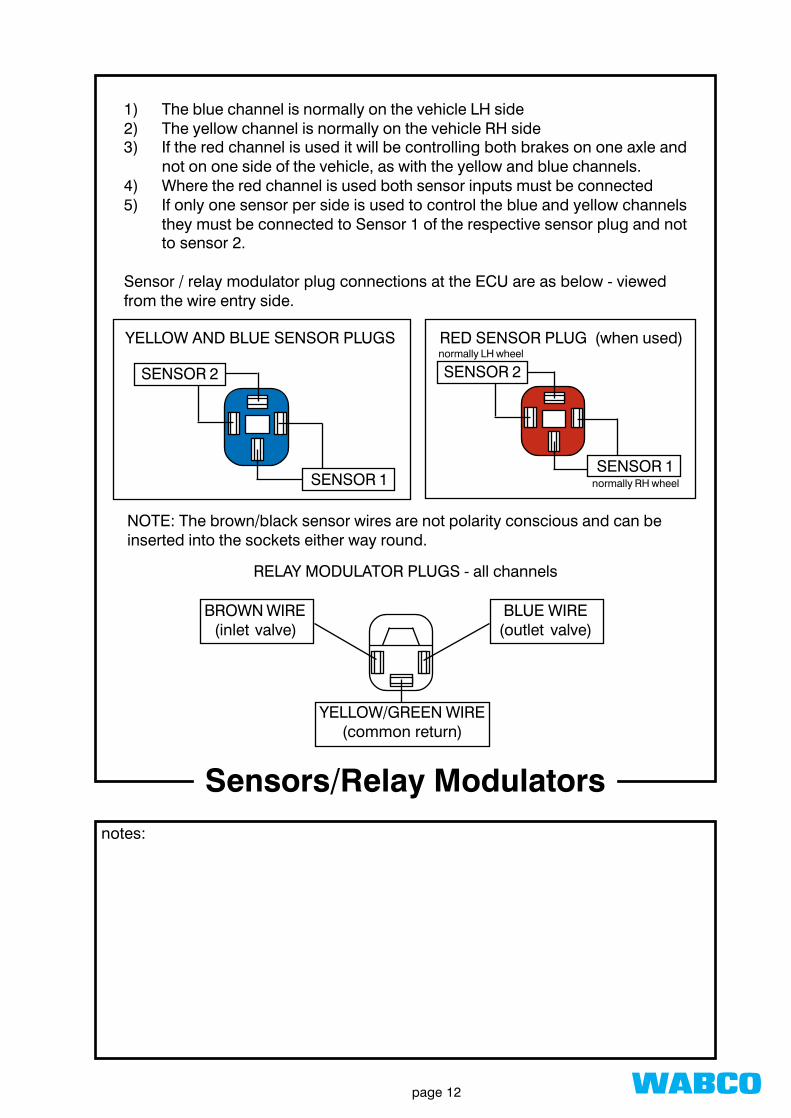
1) The blue channel is normally on the vehicle LH side2) The yellow channel is normally on the vehicle RH side3) If the red channel is used it will be controlling both brakes on one axle and
not on one side of the vehicle, as with the yellow and blue channels.4) Where the red channel is used both sensor inputs must be connected5) If only one sensor per side is used to control the blue and yellow channels
they must be connected to Sensor 1 of the respective sensor plug and notto sensor 2.
Sensor / relay modulator plug connections at the ECU are as below - viewedfrom the wire entry side.
NOTE: The brown/black sensor wires are not polarity conscious and can beinserted into the sockets either way round.
RED SENSOR PLUG (when used)YELLOW AND BLUE SENSOR PLUGS
SENSOR 2
SENSOR 1
BROWN WIRE(inlet valve)
BLUE WIRE(outlet valve)
YELLOW/GREEN WIRE(common return)
RELAY MODULATOR PLUGS - all channels
Sensors/Relay Modulators
SENSOR 2
SENSOR 1
normally LH wheel
normally RH wheel

wabcopage 13
notes:
MODULATORS
A RED BASE PLATE - BOTH ACTUATORS ON SINGLE AXLEB YELLOW BASE PLATE - ACTUATORS NORMALLY ON RH SIDEC BLUE BASEPLATE - ACTUATORS NORMALLY ON LH SIDE
SENSORS
A RED BASEPLATE - SENSOR 2 INPUTB RED BASEPLATE - SENSOR 1 INPUTC BLUE BASEPLATE - SENSOR 1 INPUTD YELLOW BASE PLATE - SENSOR 1 INPUTE BLUE BASEPLATE - SENSOR 2 INPUTF YELLOW BASEPLATE - SENSOR 2 INPUT
Sensor/Modulator, channeland Wheel Assignments

wabcopage 14
Sensor/Modulator inputson ECU Baseplate
notes:
6S/3M
4S/3M
4S/2M
2S/2M
C B A
EC
FD
AB
C B A
ABC D
C B
EC
FD
C B
DC
B U Y E R D
B U Y E R D
B U Y E R D
B U Y E R D
Modulators (3 pin)
Sensors (4 pin)

wabcopage 15
notes:
For tractor units and drawbar trucks not fitted with an ABS power cable toISO 7638, the following shows what is required and how it is installed.
ISO 7638 POWER CABLE (12 metre - 24volt) 446 010 012 2PARKING SOCKET (tractors only) 446 008 600 2DASHBOARD WARNING LAMP (red/amber - 2W typical) CUSTOMER SUPPLYFUSES CUSTOMER SUPPLY
RED BATTERY POSITIVE THROUGH 25 AMP FUSERED/WHITE IGNITION SWITCHED THROUGH 5 AMP FUSEBROWN COMMON RETURN TO BATTERY NEGATIVEBROWN/BLUE COMMON RETURN TO BATTERY NEGATIVEYELLOW/BLUE DASHBOARD ABS WARNING LAMP
For vehicles with a supplementary power cable, the dashboard warning lamp canalso be controlled via pin 2 of 24S, thereby removing the need to observe theheadboard warning lamp when the ISO 7638 power cable is absent from the trailer
ISO 7638CABLE
ISO 7638 Power Supply
BATTERY
1
2
5
3
4
2
25 Amp Fuse Red6mm
1.5mm
1.5mm
1.5mm
6mm
1.5mm
* Note:Fuse In Warning Light CircuitAt Customers Discretion.Do Not Use Fuse FromRed/White Wire.
Optional Cable
To Pin 2 Of 24S
24S
Warning Lamp (2w)-Dashboard
ISO 7638Power Cable
IgnitionSwitch
Red/White
Blue/Yellow
Brown/Blue
Brown
5 Amp Fuse
5 Amp Fuse*

wabcopage 16
notes:
For correct assembly, fit together as shown below.
1. Prepare cable / strip ends.2. Feed through clamping nut ; back cover ; rubber washer ; clamping plate
and rubber seal.3. Insert wires into relevant pins.
note: 2 pin sizes for 2 wire sizes
4. Check full insertion through view hole and crimp the pin wall around barewire.
5. Push barbed pins firmly into the iso connector as detailed below.
Red 6mm2
Red/White1.5mm2
notused
Yellow/Blue 1.5mm2
Brown 6mm2
Brown/Blue1.5mm2
ISO 7638CABLE
CLAMPINGNUT
BACKCOVER
RUBBERWASHER
CLAMPINGPLATE
RUBBERSEAL
PINS -5 off(2 sizes)
ISO 7638SOCKET
ISO 7638 - Assembly

wabcopage 17
notes:
24N/24S/ISO7638 Power Supply
Headboard Warning Lamp
24N
24S
ISO 7638
Chassis MountedJunction Box
5-Core Cable
5-Core Cable
24S/24N Relay
24S/ISO7638 Relay
TerminalBlock
ECU Power Plug
ECU Housing
12345
4
1
1
2
6
12345
wabcopage 18
notes:
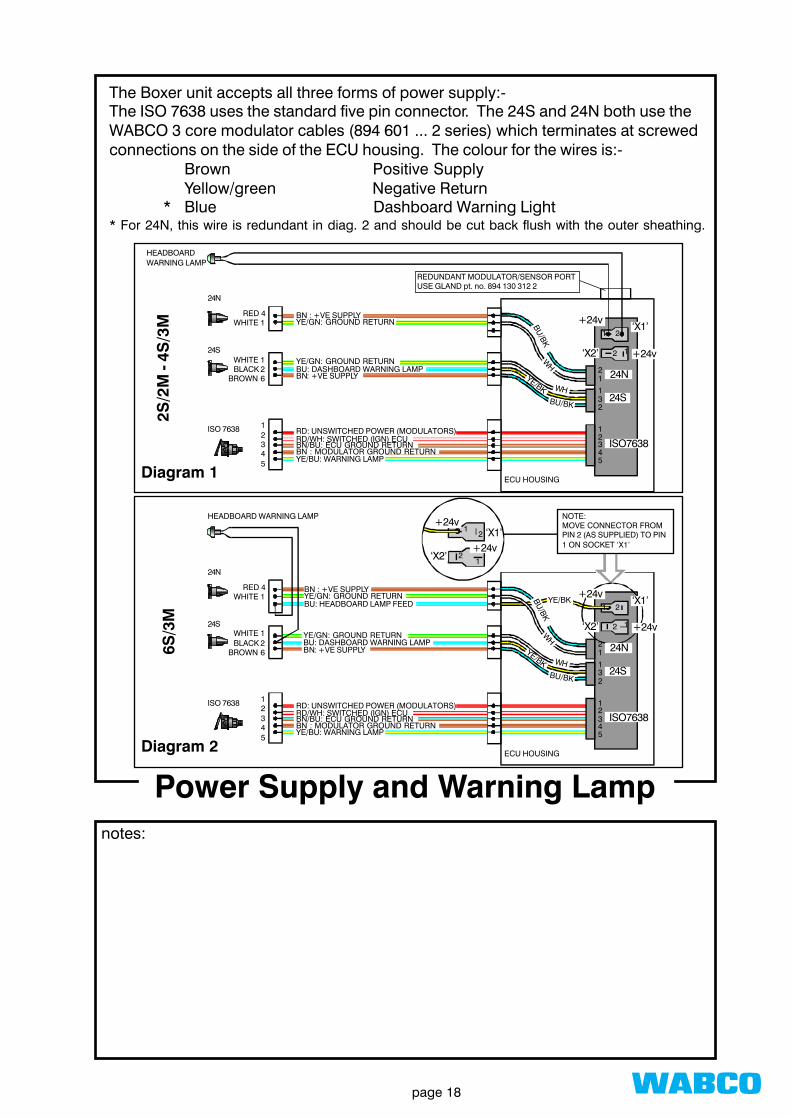
The Boxer unit accepts all three forms of power supply:-The ISO 7638 uses the standard five pin connector. The 24S and 24N both use theWABCO 3 core modulator cables (894 601 ... 2 series) which terminates at screwedconnections on the side of the ECU housing. The colour for the wires is:-
Brown Positive SupplyYellow/green Negative Return
* Blue Dashboard Warning Light* For 24N, this wire is redundant in diag. 2 and should be cut back flush with the outer sheathing.
Power Supply and Warning Lamp
2S/2
M -
4S/3
M ‘X1’
‘X2’
+24v
+24v
1 2
2 1
31
12
32
2
1
54
24N
24S
ISO7638
BU/BK
WH
WHBU/BK
YE/BK
BN : +VE SUPPLYYE/GN: GROUND RETURN
YE/GN: GROUND RETURNBU: DASHBOARD WARNING LAMPBN: +VE SUPPLY
RD: UNSWITCHED POWER (MODULATORS)RD/WH: SWITCHED (IGN) ECUBN/BU: ECU GROUND RETURNBN : MODULATOR GROUND RETURNYE/BU: WARNING LAMP
HEADBOARDWARNING LAMP
24N
24S
ISO 7638
RED 4WHITE 1
WHITE 1BLACK 2
BROWN 6
12345
ECU HOUSING
REDUNDANT MODULATOR/SENSOR PORTUSE GLAND pt. no. 894 130 312 2
Diagram 1
6S/3
M
‘X1’
‘X2’
+24v1 2
2 1
31
12
32
2
1
54
24N
24S
ISO7638
BU/BK
WH
WHBU/BK
YE/BK
BN : +VE SUPPLYYE/GN: GROUND RETURN
YE/GN: GROUND RETURNBU: DASHBOARD WARNING LAMPBN: +VE SUPPLY
RD: UNSWITCHED POWER (MODULATORS)RD/WH: SWITCHED (IGN) ECUBN/BU: ECU GROUND RETURNBN : MODULATOR GROUND RETURNYE/BU: WARNING LAMP
HEADBOARD WARNING LAMP
24N
24S
ISO 7638
RED 4WHITE 1
WHITE 1BLACK 2
BROWN 6
12345
ECU HOUSING
+24v
YE/BKBU: HEADBOARD LAMP FEED
NOTE:MOVE CONNECTOR FROMPIN 2 (AS SUPPLIED) TO PIN1 ON SOCKET ‘X1’
‘X1’
‘X2’
+24v1
21
+24v2
Diagram 2

wabcopage 19
24S Supplementary Powernotes:
THERE EXISTS THREE BASIC FORMS OF ABS POWER SUPPLY FORTRAILERS. THEY ARE AS FOLLOWS;
➧➧➧➧➧ 24S, A SECOND SOURCE OF CONSTANT POWER➧➧➧➧➧ ISO 7638, A DEDICATED ABS POWER SUSY➧➧➧➧➧ 24N, A FEED FROM THE STOP LIGHT CIRCUIT
TRAILERS SHOULD BE WIRED TO SELECT THE HIGHEST PRIORITY OF POWERAVAILABLE. THE 24N (STOP LIGHT CIRCUIT) SHOULD ONLY BE REGARDED ASAN EMERGENCY "GET YOU HOME" SETUP.
MOST VEHICLES DO NOT HAVE AN ISO 7638 POWER SUSY. THOSE FITTEDWITH A 24S SUSY ARE USUALLY NOT CONNECTED AT THE RELEVANT PINSAND ARE THEREFORE ONLY USING THE STOP LIGHT 24N CIRCUIT TO POWERTHE ABS.
THE DIAGRAM BELOW SHOWS HOW TO CONNECT THE 24S SUSY AND PRO-VIDE A DASHBOARD ABS WARNING LIGHT.
DO NOT FEED THE DASHBOARD WARNING LIGHTTHROUGH THE 12 AMPFUSE POWERING PIN 6.USE AN ADDITIONAL 2AMP FUSE IF REQUIRED.
THIS WILL GIVE A CONSTANT POWER SUPPLY TO THE TRAILER PROVIDING THETRAILER IS WIRED TO ACCEPT A 24S SUPPLY
BATTERY
IGNITION SWITCH
24SSUSY
1
6
2
RED/AMBERDASHBOARD W/L (2 Watt)
2 AMP(Optional)
12 AMP
BATTERY

wabcopage 20
ABS Information Lamp (i)notes:
Information lamps are controlled by the information module and serve to inform thedriver that his vehicle is coupled to a trailer without ABS. Unlike the ABS warninglight, there are no legal requirements, fitment being at the discretion of the VM's(Vehicle Manufacturers).The lights are usually orange or yellow and either resemble the tractor ABS warn-ing light with a number or depict a trailer crossed out and the letters ABS under-neath.Detection of current to the trailer ABS is via pins UES and UA. Pins RK and AKtogether with the segregating relay, control a latching system and separate themotor vehicle brake lights from those on the trailer.
How it works:
BATTERY
IGNITIONSWITCH
ISO7638
24N
5
2
4
BRAKELIGHTS
B/LSWITCH
B/L SEGREGATINGRELAY
ABS W/L
INFO LAMP7.5 A
5 A
(VM's)BATTERY
ABS
2
ABS
TRAILER
INFORMATION
LAMP
OR
IL
UES
ZS
RKAK
UA
INFOMODULE
The module first determines if the tractor has a trailer attached to it by reading theresistance in the indicator circuit via the 24N connector.For an infinite resistance, it assumes no trailer is present and keeps the light OFF. Ifa resistance exists, the module would know that a trailer is coupled and look for acurrent drain to the trailer ECU on pin 2 of the ISO 7638 susy.A drain on this pin indicates that the trailer is equipped with ABS; the informationlight will remain OFF. The light turns ON only if no drain is observed, indicating thatABS is not fitted.

wabcopage 21
notes:
ABS Information Lamp (ii)
PUSHTO CLOSESWITCH
7.5 A FUSE
INFOMODULE
INFO LAMP
24S / 24N Power Supply
Vehicles fitted with an information module may not recognise the presence of anABS system when towing trailers which are powered by either the supplementaryor the stoplight circuit. Operators wishing to dispense with the information lampcan adopt one of the following:-
➀➀➀➀➀ Remove lamp and blank off aperture in dash panel.
or
� Discard information module. Identify terminals UES and UA on the basehousing and bridge together using a suitable wire link.
or
� Fit an additional relay and push button 'latch out' switch.
How it works
On picking up a trailer without ABS or one which is powered by an alternative sup-ply (24S/24N), the light will illuminate. The adjacent button will latch the relay andturn the lamp off.Once the ignition has been keyed off, the circuit will reset itself to normal operation.

wabcopage 22
Sensor and Modulator Function

wabcopage 23
notes:
Axle Installation
1 Pole wheels must run square to the axle.
2 Pole wheel teeth must be free from burrs or bruising- NO DAMAGE ALLOWED.
3 Sensors must be central over the pole wheel teeth.
Hub
Stub axle

wabcopage 24
Sensor Output Voltagenotes:
single wheel revolution
Ideal
MaximumPermissible
Variation
Time à ß
Volta
ge à
low frequency / low output voltage
high frequency / high output voltage

wabcopage 25
Sensor Output Signalnotes:
The output voltage from the sensor is AC. From this the electronic control unit(ECU) determined the individual wheel speed, which is proportional to the AC fre-quency. Moreover, the ECU continually assesses any rate of change in frequencywhich is a direct measure of the wheel’s deceleration (or acceleration). Togetherwith the speed information it establishes whether corrective action is required toprevent the onset of wheel locking.
To work effectively the output signals from the sensors must be readily understoodby the ECU.
They must:1) Give sufficient output voltage;2) Have a reasonably steady output voltage at any given wheel speed; and3) The waveform should not deviate significantly from its sinusoidal pattern.
To these ends:1a) The air gap between polewheel and sensor should be maintained at the
absolute minimum - generally less than 0.5mm.2a) Polewheel run-out and bearing clearances should be kept as small as
possible - the combined effect on change in air gap not exceeding 0.2 mm.3a) The polewheels should be free of any damage, the change in air-gap
between adjacent teeth being no more than 0.04mm.
Providing the above criteria are satisfied:1b) The output voltage will exceed the minimum allowable figure of 0.1 v RMS.
(this assumes that the wheel is turning at a constant speed of approx.0.5rev/sec.)2b) The ratio of maximum to minimum output voltage when rotating at
constant speed will not exceed 2.2 : 1 i.e. if the min value is 0.3v the maxmust not exceed 0.66v.
3b) The change in voltage amplitude between adjacent teeth will be insidespecification. One deviation greater than 30% or two deviations greaterthat 20% is cause for rejection. ( A diagnostic controller must be used asverification whenever polewheel damage is suspected ).

wabcopage 26
notes:
ABS Relay Valve Function (1)
The relay valve function is critical and dependent upon thepreset characteristics of each individual solenoid. Conse-quently the unit is NON-SERVICEABLE in nature and shouldproblems arise the entire assembly must be replaced.
3
1
4
2
3
1
4
2
Example 1:Supply pressure at port 1 (e.g. 8 bar), no control pressure at port 4.The spring (S) forces valve (V) against the outer (inlet) valve seat thussealing off supply port 1 against piston chamber (C).
Example 2:Supply pressure at port 1 (e.g. 8 bar), and control pressure at port 4 (e.g.1 bar).The control pressure at port 4 flows past the two solenoids ( IV
P [inlet]
and OVP [outlet] ) into the piston chamber (D) and forces piston (E)downwards thereby closing the outlet valve (inner seal) and opening theinlet valve (outer seal). This allows air to flow from port 1 to port 2 andinto the brake chamber(s). The area of the piston is the same aboveand below, that means as soon as the pressure at port 2 equals that inchamber (D), the piston returns to a balanced position in which both theinlet and outlet valves are closed. If the control pressure is reduced,piston (E) is forced upwards the exhaust valve opens and excesspressure is vented through port 3 until a balanced condition is againreached.
If an ABS cycle is in operation and the ECU selects the ‘pressure hold’phase and the driver releases the brake at the same instant the pressureabove the piston in chamber (D) is vented via port 4 through the non-return valve (F).
Valve Operation
Pressure increase
Both solenoids non-energised - IVP open and OV
P closed.
Control pressure present at port 4.Exhaust valve closes, inlet valve opens.Air flows from ports 1 to 2.
IVP OVP
F
E
C
SIV
OVD

wabcopage 27
notes:
ABS Relay Valve Function (2)
The relay valve function is critical and dependent upon thepreset characteristics of each individual solenoid. Conse-quently the unit is NON-SERVICEABLE in nature and shouldproblems arise the entire assembly must be replaced.
3
4
1
3
4
1
2
Pressure hold
Inlet valve solenoid IVP is energized, its core is raised, therefore,despite the presence of control pressure at port 4, the flow of air fromthe control line to the upper chamber (D) is interrupted.Pressure between upper and lower chambers equalizes.Valve (IV) is forced upwards by the spring (S) sealing the chamber (C)from both supply and exhaust.Air cannot, therefore, flow from ports 1 to 2 nor from 2 to atmosphere.
Pressure release
Outlet valve solenoid OVP is energized.Control pressure is prevented from entering upper chamber. Theraised seal at the base of solenoid OVP vents the pressure in the upperchamber (D) through the central opening in the piston. Piston (E)moves upwards, valve IV is forced against the valve seat and air fromthe lower chamber, delivery port and the brake chamber(s) is vented toatmosphere.2

wabcopage 28
Warning Lamp Functionand Error Memory
wabcopage 29
ABS Warning Lampnotes:
DISABLED THE DEFECTIVE SECTION.or CLOSED DOWN THE APPROPRIATE DIAGONAL. (MOTOR VEHICLES ONLY)or SWITCHED OFF THE ENTIRE ABS. (WORST CASE)
For both motor vehicles and trailers the warning lamp is fed directly between a livesupply and the warning lamp terminal on the ECU. If a fault condition arises, theECU grounds the connection, thereby completing the circuit and illuminating thewarning lamp. When no fault condition exists, the ECU breaks the connection toground and the lamp extinguishes
Motor Vehicles And TrailersWith Permanent Power
If the ECU is receiving power from the brakelight circuit only, the driver will have to ob-serve the action of the green head boardwarning light. Wheel speed signals can onlybe checked when the vehicle is in motion andduring brake applications. Whenever thebrake pedal is depressed at speeds less than~7kph, the warning light will come on andremain on for that braking period. If the vehi-cle exceeds this speed, the warning light willbriefly flash and remain off until the next brakeapplication. Illumination of the warning lightthroughout braking at speeds above ~7kph,indicates a system fault has been detected.
The ABS Warning Lamp informs the driver that the ECU's internal safetycontroller has detected a fault and has either;
On switching the ignition on, the warninglamp will illuminate. As a complete sen-sor check is unable to be made until thevehicle is in motion, the lamp will remainon. At ~7kph the warning lamp will extin-guish and remain off for the duration ofthe journey, whether the vehicle is station-ary or moving. If a fault is detected thewarning lamp will illuminate and remainon. On stopping the vehicle, switchingthe ignition off and back on again, thesafety circuit will reset itself. If the faultwas intermittent and is no longer present,then on moving off the lamp will extinguishin the normal manner otherwisethe light will remain on.
Trailers Powered FromThe Brake Light
In the event of the ABS warning light illuminating during use, the vehicle should bedriven with due care and attention directly to a workshop where a qualified personcan diagnose and rectify the fault. As the ABS system operates independentlyfrom the conventional braking system, normal braking will still be possible.
Faults are stored in the ECU's nonvolatile memory for subsequent analysis in theworkshop.

wabcopage 30
The ECU contains a main and safety controller which are constantly assessingwhether the system is in good working order. In addition to checks within the ECUitself, the controllers are constantly checking the external wiring for short/opencircuit connections and the plausibility of the wheel speed signals. These checkscommence immediately the ignition is switched on. If no faults exist in the interme-diate (or buffer) memory when moving off , providing satisfactory wheel speedsignals are detected, the warning lamp will extinguish at about 7kph after which itshould remain off whether moving or stationary.The buffer memory controls the warning lamp and if a fault is subsequently de-tected it will immediately put the message into the buffer, disable the relevantsection(s) of the ABS and illuminate the warning lamp. If the fault was of a tempo-rary nature ( e.g. poor electrical connection on a sensor cable) the action of switch-ing off the power (ign. switch) will automatically transfer the fault from the buffer tononvolatile memory. A temporary fault of this type will result in the buffer memorybeing clear when the ignition is next switch on, in which case the warning lamp willagain extinguish on moving off. However if the fault is of a permanent nature (cur-rently existing) it will be put into the buffer memory again and the warning lamp willfail to extinguish.
SafetyController
MainController
BufferMemory
NonvolatileMemory
OperatingCircuits
WarningLamp
Vario-CFault Storage in Error Memory (i)
notes:

wabcopage 31
All faults, whether in the buffer or nonvolatile memory, are accessible by compacttester, diagnostic controller or flash code. Full instructions are provided on faultidentification/clearance with both the compact tester and the diagnostic controller.The following give guidance on fault identification and clearance using flash code.Before describing the flash code itself the following should be noted.
1) No fault can be cleared down that currently exists. i.e. one which is in thebuffer memory.
2) As a matter of priority, fault messages that are contained in the buffer arepresented first. If the fault is current, i.e. cannot be moved across tononvolatile memory by keying the ignition off and back on, it will be presentedto you again and must be rectified before proceeding further.
3) Faults of a dynamic nature, i.e. those relating to the sensor signal (large airgap, excessive polewheel run-out) can always be cleared because, unlike abroken wire, the ECU is unable to assess whether the condition has beenrectified until the vehicle is in motion.
4) The entire nonvolatile memory can be stacked with numerous faults butproviding none are current when moving off the warning lamp will extinguishin the usual manner.
5) Despite however many times the same fault has been recorded a singleclear ance action will clear all faults in that location.
notes:
Vario-CFault Storage in Error Memory (ii)

wabcopage 32
Blinkcode Operation

wabcopage 33
On applying power the headboard warning lamp (and, if applicable, dashboardwarning lamp) will light up together with the red LED inside the ECU. In flash codemode all warning lamps should flash out together - verification that the warninglamp wiring is OK.To activate the flash code it is necessary to bridge pins 6 and 10 on the diagnosticconnector - see above, normally a pre-wired plug will be provided for this purposein the housing. Providing the supply voltage is adequate (min. 23.5 volts) the LEDwill start to flash after approx. 5 seconds as shown below. The message will berepeated indefinitely until the bridge link is removed, in which case the lamp willcontinue to flash out to the end of the current sequence. It should be noted that,depending upon the point in the cycle when the bridge link is removed, the se-quence may repeat itself once more before stopping at which point all warninglamps and red LED will remain lit.
After removing the four M6 allen screws the ECU can be opened up and whenhinged down will appear as below.
Fault Identification by Flash Code (i)notes:
bridge these two pins
Red LED

wabcopage 34
notes:
The 2.5 sec. flash is the ECU’s response to your request and the following numberof 0.5sec. pulses indicates the type of system installed (see table #1).
1 flash 6S/3M ( 6 sensors / 3 modulators )2 flashes 4S/3M3 flashes 4S/2M4 flashes 2S/2M
If the memory is clear, no other groups of flashes will be presented and after re-moval of the bridging link the message will continue to the end of the sequence.If an error exists in the memory then a code usually made up of two groups offlashes will follow the system code.
Table #1
5 sec. delay 2.5 sec.
2.5 sec. 0.5 sec.
lamp on
lamp off
pins
6 &
10
brid
ged
6S/3M
4S/3M
4S/2M
2S/2M
Fault Identification by Flash Code (ii)

wabcopage 35
notes:
The following shows a typical complete message with system fault:- in this casesystem type 2 (2S/2M) followed by error code 1-3, air gap sensor B.
All fault codes are listed in the following table. Codes may appear which are notlisted. If these can be satisfactorily cleared they should be ignored. If unlistedcodes cannot be cleared or are frequently being recorded the fault probably lieswithin the ECU and contact should be made with WABCO Technical Services forfurther advice.
5 sec. delay 2.5 sec.
2.5 sec. 1 sec.
lamp on
lamp off
pins 6 & 10 bridged
aknowledgement
system
error code
repeat of code
Fault Identification by Flash Code (iii)

wabcopage 36
* 0 0 System OK* 1 1 Parameterize system ......... (re-initialise ECU - see separate sheet)* 1 2 Sensor B ........................... Sensor speed jump/ excessive polewheel run-out* 1 3 Sensor B ........................... Air gap* 1 4 Sensor B ........................... Break in wire, short circuit or excess ground leakage* 1 5 Sensor D ........................... Sensor speed jump/ excessive polewheel run-out* 1 6 Sensor D ........................... Air gap* 1 7 Sensor D ........................... Break in wire, short circuit or excess ground leakage* 1 8 Sensor A ........................... Sensor speed jump/ excessive polewheel run-out* 1 9 Sensor A ........................... Air gap* 1 10 Sensor A ........................... Break in wire, short circuit or excess ground leakage* 1 11 Sensor C ........................... Sensor speed jump/ excessive polewheel run-out* 1 12 Sensor C ........................... Air gap* 1 13 Sensor C ........................... Break in wire, short circuit or excess ground leakage* 1 14 Sensor F ........................... Sensor speed jump/ excessive polewheel run-out* 1 15 Sensor F ........................... Air gap* 2 0 Sensor F ........................... Break in wire, short circuit or excess ground leakage* 2 1 Sensor E ........................... Sensor speed jump/ excessive polewheel run-out* 2 2 Sensor E ........................... Air gap* 2 3 Sensor E ........................... Break in wire, short circuit or excess ground leakage* 2 4 Modulator A ...................... Inlet valve, break in wiring* 2 5 Modulator A ...................... Outlet valve, break in wiring* 2 6 Modulator B ...................... Inlet valve, break in wiring* 2 7 Modulator B ...................... Outlet valve, break in wiring* 2 8 Modulator C ...................... Inlet valve, break in wiring* 2 9 Modulator C ...................... Outlet valve, break in wiring* 2 10 Modulator A ...................... Inlet valve, short to earth/ground* 2 11 Modulator A ...................... Outlet valve, short to earth/ground* 2 12 Modulator B ...................... Inlet valve, short to earth/ground* 2 13 Modulator B ...................... Outlet valve, short to earth/ground* 2 14 Modulator C ...................... Inlet valve, short to earth/ground* 2 15 Modulator C ...................... Outlet valve, short to earth/ground* 3 2 Contact 3 (supply plug) earth missing* 3 3 Undervoltage* 3 4 Break in wiring, contact 7 (e.g. retarder)* 3 5 Short circuit, contact 7 (e.g. retarder)* 3 6 Earth break, modulator A [red]* 3 7 or ECU ◊* 3 8 Earth break, modulator B [yellow]* 3 9 or ECU ◊* 3 10 Earth break, modulator C [blue]* 3 11 or ECU ◊* 3 13 Permanent power at contact 7 (e.g. retarder)* 3 12 Overvoltage* 4 6 Modulator A ...................... inlet valve short circuit to positive* 4 7 Modulator A ...................... Outlet valve short circuit to positive* 4 8 Modulator B ...................... inlet valve short circuit to positive* 4 9 Modulator B ...................... Outlet valve short circuit to positive* 4 10 Modulator C ...................... inlet valve short circuit to positive* 4 11 Modulator B ...................... Outlet valve short circuit to positive* 4 12 No operative modulator connected* 4 13 No operative modulator connected* 4 14 Short circuit to positive
◊ If this fault is indicated, the system configuration flashed out is meaningless. Before changing the ECU,re-check the earth lead (yellow/green) of each valve against outlet and inlet valves again.
ABS Vario-C Flash Code
System Code
Error CodeCause of Faultsee
table #1

wabcopage 37
Vario-C2 ECU Initialisation (i)notes:
After all installation checks have been satisfactorily completed the ECU will need tobe ‘initialised’. This means that the ECU needs confirmation that the system towhich it is currently connected is the one which it will relate all future faults to. It willnot, for example, assume a satisfactory 4S/2M system when the original fitmentwas 6S/3M - the configuration changing in service by virtue of, say, the red sensorand modulator plugs becoming disconnected.
Initialisation is simply as follows:
1) Firstly connect all sensors and modulator plugs on the ECU base plate.The white/green power plug should be fitted last.(Failure to observe this basic rule will, if voltage is present at the powerplug, cause numerous faults to be stacked in the memory as the ECUsees all sensor and modulator wiring open circuit).
2) Apply power to the ECU via one of the relevant connections at the headboard.
3) Fit the diagnostic plug in the ‘active’ position (see flash code instructions).After approximately 5 sec. the following codes will appear - see flashcode listings for full interpretation of error codes.
1-1-1 ............... 6S/3M system2-1-1 ............... 4S/3M system3-1-1 ............... 4S/2M system4-1-1 ............... 2S/2M system
The first digit represents the system type which the ECU sees as currently installedand the ‘-1-1’ is the ECU’s way of asking ‘is this correct?’.
4) Remove the diagnostic plug and wait for the LED to stop flashing andgive a continuous light. Do not switch the power off.
cont.......

wabcopage 38
Vario-C2 ECU Initialisation (ii)notes:
5) Wait 5 secs. and return the diagnostic plug to the “active” position. Theflash code should then reveal 1-0-0 (6S/3M) etc. - initialisation completeand memory clear. If any faults have inadvertently been stored in thememory these will need to be cleared using the normal procedure (seeflash code booklet) until the message 1-0-0: 2-0-0 etc. as applicable, isreceived.If error messages have been stored in the memory before initialisation,after clearing each fault the ECU may ask for confirmation of the systemtype i.e. it will reveal error code ...-1-1 which must be answered beforeany other fault is revealed. To clear a fault message usually entailsSWITCHING OFF the power at the end of the flash sequence whereas inconfirming the system type it MUST remain on. Failure to observe thesebasic rules can result in lost time and frustration. The answer is simple -fully check-out the system first to ensure no faults exist before fitment ofthe ECU. Initialisation should then take less than 1 minute.
6) Return the diagnostic plug to the ‘inactive’ position.

wabcopage 39
Vario-C2 ECU “Clear All” Functionnotes:
Vario C Trailer ABS 'Clear All Faults' Facility
All Vario C ECU's produced after week 26 of 1994 (2694) incorporate a clearall function. This makes fault clearance much simpler and is intended to be usedwhen, for example the power has accidentally been applied to the ECU before allsensor/modulator connections have been made. To use the clear all function theremust be no current faults i.e no faults in the buffer memory. Verify by checking thatall wiring and connections are correctly made then temporarily remove then recon-nect the power.
To Clear All FaultsActivate the flashcode (bridge pins 6 and 10 on the diagnostic plug). After
about 5 seconds the warning lights and red ECU LED will start to flash - see flashcode booklet for full diagnosis instructions. At the end of the 2.5 second 'bulb on'sequence in the following 7.5 seconds the diagnostic plug should be removed forgreater than 1 second and then replaced. The first fault in the memory will then bepresented after which the next sequence will give the 'all clear' as below.
*In this interval remove diagnostic plug (break connections 6 & 10) for greater than1 second.
Note: If the system had not been initialised prior to the errors being inadvertentlyput into the memory although all faults will have been erased the initialisation code(1,1) will replace the all clear message. Initialisation must then be carried out usingthe appropriate procedure.N.B do not forget to stow the diagnostic plug in its inactive position after carryingout this procedure.
Bulb Off
Bulb On
Pins Bridged 5 secs
2.5 secs
2.5 secs 2.5 secs7.5 s*
syst. typee.g 3,(4S/2M)
fault code e.g 2,3broken wire sensor E
system clear

wabcopage 40
General Information
wabcopage 41
Useful Datanotes:
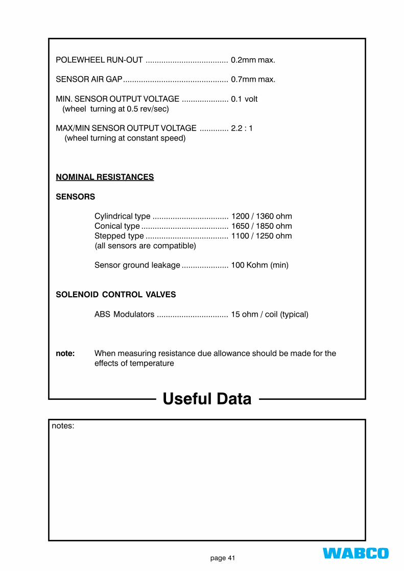
POLEWHEEL RUN-OUT ..................................... 0.2mm max.
SENSOR AIR GAP............................................... 0.7mm max.
MIN. SENSOR OUTPUT VOLTAGE ..................... 0.1 volt (wheel turning at 0.5 rev/sec)
MAX/MIN SENSOR OUTPUT VOLTAGE ............. 2.2 : 1 (wheel turning at constant speed)
NOMINAL RESISTANCES
SENSORS
Cylindrical type .................................. 1200 / 1360 ohmConical type ....................................... 1650 / 1850 ohmStepped type ..................................... 1100 / 1250 ohm(all sensors are compatible)
Sensor ground leakage ..................... 100 Kohm (min)
SOLENOID CONTROL VALVES
ABS Modulators ................................ 15 ohm / coil (typical)
note: When measuring resistance due allowance should be made for theeffects of temperature

wabcopage 42
Common Faultsnotes:
Sensor air gap too large
Wheel bearing clearance excessive
Unacceptable sensor ground leakage
Defective sensor or water in connectors
Sensor wiring damaged in vicinity of hub
Rubbing on brake drumUnprotected and chafing where passing through holein brake back plate
blown fuses
Defective relays in power supply module- open circuit coil or high resistance contacts

wabcopage 43
Helpful Hintsnotes:
Always re-grease friction bush and reset sensorwhenever drums / hubs removed.
Don’t damage the polewheel teeth.
Don’t rock the wheels / hubs when refitting - canknock sensor back.
Ensure connector at back plate is fully home andsecure.
Regularly check pipework / cabling for security.
Check that all modulators exercise at “switch-on”(pressurise brake lines first)
Always switch-off ignition before disconnectingsensor / modulator plugs or removing the ECU.
Remove the ECU from the vehicle before carryingout electric welding work.
If the error memory reveals, for example, ‘air gapwheel C’ and the location of sensor C is uncer-tain, measure the sensor resistance at sensor 1input - blue channel (wheel C) and unplug eachwheel sensor at the extension cable near thebrake back plate. The plug which, when discon-nected, causes the meter to read open circuit hasidentified sensor C’s location.

wabcopage 44
ECU’s and Weldingnotes:
The following applies to all WABCO ECU's and related system components. Toavoid the possibility of damage to the ECU while welding, we recommend that thefollowing precautions are adopted:
➟ DISCONNECT THE HARNESS OR POWER SUPPLY PLUG FROM THE ECUBEFORE UNDERTAKING ANY WELDING WORK ON THE VEHICLE.
➟ IN THE CASE OF TRAILER SYSTEMS IT IS ALSO RECOMMENDED THATALL MODULATOR AND SENSOR PLUGS ARE REMOVED AT THE ECUBASEPLATE.
➟ DO NOT USE ELECTRICALLY OPERATED COMPONENTS AS AN EARTHFOR WELDING.

wabcopage 45
Polewheel Handlingnotes:
ABS Polewheels are precision made components which meet stringent design,manufacturing and quality control requirements. To avoid damage they mustalways be handled with care.
For the correct handling of polewheels the following instructions must beobserved during storage, initial installation and in service
Strike the polewheel.
Attempt to repair polewheels
Use the polewheel as a load bearing surface
Stand the hubs with the polewheel face down
NEVER ...
ALWAYS ...Protect the polewheels from the possibility of damage.
Replace damaged polewheels
Inspect the polewheels carefully prior to assembly payingparticular attention to tooth damage, for example;.
BURRS CHIPS DENTS