trailer technical information -...
TRANSCRIPT

TrailerTechnical
Information
Surge Brake Actuators • Disc Brake SystemsRubber Torsion Axles • Oil Bath Lubrication
MasterCraft Technical TrainingVonore, Tennessee USA
A MasterCraft Technical Services Publication
MasterCraft University 2008-2009 • Trailers • Page 1

3.Lowerthetrailerontotheball.4.Checkthetrailerballandcouplertoverifyfitup.5.Closethelatch.Youwillhearthelatchclickintothe
closedposition.6.Insertthekeeperpinintothesideofthecoupler.7.Attachsafetychains,lightsandbreakawaycable
tothetowvehicle.8.Youarenowreadytobegintowing.
Toremovethetrailerfromthetowvehiclefollowtheprocedurebelow.
1.Removekeeperpinfromthesideofthecoupler.2.Slide back the release button on the latch. The
couplermechanismshouldopenfreely.3.Raisethetrailerofftheball.4.Unhooksafetychains, lightsandbreakawayca-
ble.5.Closelatchandinsertkeeperpin.
d.Care, Maintenance and Inspection–Typicallythereis no special maintenance required for the surgebrakeactuator.However,itisimportantthatthefluidinthemastercylinderbecheckedonaregularbasisand replacedevery2 yearswithaDOT3approvedbrakefluid.Byusingageneraltypelubricationsprayonmovinglatchcomponentsyoucanassurethatthelatchwillworkfreely.
The surge brake actuator has the unique option ofbeingabletobepartiallydisassembledwithoutthein-convenienceofhavingtobleedthebrakes.Thiscanbedoneifanymaintenanceneedstobeperformed.
Toremovetheinnerhousing,simplyremovethesnaprings from the two 3/4” pins that run thru the outerhousingandslidethepinsout.Theinnerhousingwillthenbeabletoberemovedfromtheouterhousing.
I. Surge Brake Actuators
a. Overview – The actuator used on MasterCrafttrailersforthe2009modelyearisaReliableSurgeBrakeActuator. It hasa ratingof 7500#GVWRwithamaximum600#tongueload.Theactuatorisdesignedtobeusedwitha2” trailer ball only.Thetrailerballmustbebetween1.97”and2.00”.Trailerballslargerthan2.00”willnotallowthelatchto close and trailer balls smaller that 1.97” allowfor too much movement in the ball socket whichcanresult indamage to theactuator. The trailerballmustmeetorexceedtheGVWRofthetrailer.Wornhitchballsshouldnotbeusedandcanleadtoamultitudeofproblems.
The innerhousing isprotected fromcorrosionwithaninitiallayerofe-coatwithablackpowdertopcoat.Theouterhousingandswingtongueportionispaint-edtomatchthetrailer.Theinternalrollers,pushrod,retainingringsandlatchcomponentsarezincplatedandafinalsealantisappliedtofurtherprotectagainstcorrosion.Themastercylinderispaintedwithablackprimer.Thecaptothemastercylinderutilizesano-ringtosealagainstwaterentry.
b. Installation – In order to assure that the surgebrakeactuatorfunctionsproperlythefollowingin-stallationinstructionsshouldbefollowed:
1.Slide the actuator assembly onto the tongue at-tachmentplateandinstallthekeeperbolt.Theboltshouldhaveasmallamountofanti-seizeappliedpriortoinstallation.Checkforproperswing-awayoperation.
2.Torqueboltandnutto75ft./lbs.Thisbolttorqueshouldalwaysbemaintained.Installswingtonguepin.
c. General Operation–Forhookingup the trailer tothe tow vehicle the following procedure should beused.
1.Removethekeeperpin fromthesideof thecou-pler
2.Slide back the release button on the latch. Thecouplermechanismshouldopenfreely.
MasterCraft University 2008-2009 • Trailers • Page 2

To reassemble, slide the inner housing into the out-erhousingand insert thepinsand reattach thesnaprings.
Caution: Whenreassembling the innerhousingintotheouterhousingitisimportanttoverifythatpinsare inserted thru the rollerbushings in theinnerhousing.Failuretodosowillresultinpos-sibledamagetotheactuatorandlossofbrakes.
e.Emergency Break Away System -Thesurgebrakeactuator is equipped with an emergency break awaybrakeactuatingsystem.Shouldthetrailerbecomesep-aratedfromthetowvehiclethecableontheactuatorwillbepulledandthebrakesonthetrailerwillbeapplied.Todisengagethebrakes,withaflatscrewdriver,pressthebreakawaytabupintotheslotinthebottomoftheactuator.Theinternalmechanismisnowreset.
Typically,thebreakawaycablewillbebrokenbytheforceofthetowvehicleleavingthetrailer.Ifthisisthecasea replacementkitwillneed tobeorderedandreinstalled.Thekitwillconsistofanewbreakawaywingassemblyandcable.Toreinstallthekitremovetheinnerhousingfromtheouterhousingfollowingtheprocedurelistedabove.Feedtheballonthebreak-awaycablethrutheholeinthenoseoftheinnerhous-ingandbackaround the¾”breakawaystud in therearofthehousing.Slidethecableintotheslotinthebreakawaywingassembly.Theballonthecableand
MasterCraft University 2008-2009 • Trailers • Page 3
theheadoftheplasticbushingmustbeonthesamesideofthewing.Usingvisegripsorpliers,crimptheearsonthewing.Theearsshouldbecrimpedsothewingcannotcomeoffofthecable.Withthecableat-tachedtothewingslidetheassemblyontothepushrod bushing with the head of the bushing going onfirst. Slideon thebreakawayspringandpush ituponto thebushinguntil it is seatedagainst thewing.Applyasmallamountofsiliconegreasetothepushrodandinsertthepushrodandspringthruthebush-ing.Visuallychecktomakecertainthatthepushrodandspringareseatedagainstthebreakawayspring.Normaloperationcannowresume.
f.Bleeding the brakes - In order for the actuator tofunctionproperlyyouwillneedtobleedtheair fromthesystem.Thiscaneitherbeaccomplishedwithapneumaticpowerbleederunitormanually.Whenus-ingapneumatic bleeder a special adaptermust beusedtoadapttothemastercylinderthisisavailablefor purchase from MasterCraft.The master cylindershould be filled with a DOT3 approved brake fluid.Bothmethodsaredescribedbelow.
Thesurgebrakeactuatorusesasmallorificefittingthatmeterstheamountoffluiddeliveredtothecali-persfromthemastercylinder.Theopeninginthefit-tingisonly.030”.Itisimperativethatthemastercyl-inderbecleanofalldirtanddebris.Failuretodosomayresultinthefittingbeingpluggedthusthebrakeswillnotbeabletobebled.
1.Ontandemaxleapplicationstherearaxleonthetrailershouldbebledfirst.
2.Attachbleederhoseonthebleederscrewonthefirstwheelcylindertobebled.Submergetheop-posite end of the bleeder hose into a glass con-tainer filledwith brake fluid. The purpose of theglasscontaineristoobserveanyairbubblesinthesystem.
3.When using the pneumatic bleeder, turn on thebleederunit(30-50psi)tobeginforcingairoutofthe system. Or if using the manual method, in-serta¾”wrenchthrutheslotlocatedinthebottomplateoftheouterhousingandontothepivotstudintheinnerhousing.Thewrenchwillbeusedtoprytheinnerhousinginandouttoforcefluidthruthesystem.Usingthewrenchretracttheinnerhous-ingandhold.

g.Master Cylinder Replacement – In the event thatthemaster cylinder shouldneed tobe replaced thefollowingprocedurewillguideyouthrutheprocess.
1.Removetheswingtonguepinandswingthetrailer
tonguetotheopenposition.2.Removethemastercylindercap.3.Unhookbrakelineattherearofthemastercylinder
anddrainanyfluidfromthemastercylinder.4.Removethefour¼-20flatheadcapscrewsfrom
thetopoftheouterhousing.Themastercylindershould drop from the housing and be able to beremovedfromtherearoftheouterhousing.
5.Installthenewmastercylinderandtorquethefourflatheadcapscrewsto25ft./lbs.
6.Installthenewmastercylindercaptopreventde-brisfromenteringthereservoir.
7.Reattach thebrake lineat the rearof themastercylinder.
8.FillmastercylinderwithDOT3approvedbrakeflu-id.
9.Bleedthebrakesasdescribedintheaboveproce-dure.
4. Loosen thefirstbleeder screwone full turn. Airbubblesandfluidwillexitthescrewandappearintheglasscontainer.
5.Whenthefluidflowslowstightenthebleederscrewandreleasetheactuatorbypryingintheoppositedirectionwiththewrench.
6. Repeatsteps3thru6untilnoairbubblesappearin the stream of fluid. When complete removebleederhoseandproceedtothenextbrakecali-per.
7. To avoid air being forced back into the system,donot let themastercylinder rundryduring thebleedingprocess.Themastercylindermayneedtobereplenishedafterbleedingeachwheelcylin-der.
8. Fillthemastercylinderreservoirwithfluidandre-placethecap.Thecapshouldbetightenedjustslightlytighterthanhandtight.
MasterCraft University 2008-2009 • Trailers • Page 4

MasterCraft University 2008-2009 • Trailers • Page 5
Actuator Troubleshooting Guide
SYMPTOM CAUSES REMEDIES

Belowisanassemblydrawingoftheactuator.Pleasereferencepartnumberswhenorderingreplacements.
Parts List
Item PartNumber Description1 CAP-003 MasterCylinderCap2 ACT-6K-42 CapScrew¼-203 ACT-7.5K-01W ACT-7.5K-02W ACT-7.5K-03W OuterHousing-Weld-on OuterHousing-Bolt-on OuterHousing-SwingAway4 CAP-004 CapDiaphragm5 ACT-6K-56 SnapRing-3/4Diameter6 SA-001 ShockAbsorber7 ACT-7.5K-30 PushRod8 MC-001M MasterCylinder-Machined9 BUV-1000A-02 BUV-1000A-03 BackupValveAssembly10 ACT-7.5K-26 RollerPin11 ACT-6K-85 ActuatorSpring12 ACT-6K-31 BreakAwaySpring13 ACT-6K-79 BreakAwayBushing14 ACT-6K-69 PushRodO-Ring15 ACT-7.5K-25 FrontShockAttachingPin16 ACT-6K-23 Bushing17 ACT-6K-40 BreakAwayCable18 ACT-6K-45 KeeperPin19 ACT-6K-75 LowerRollerSpacer20 ACT-6K-24 MachinedRoller21 ACT-7.5K-17 LowerLatchPivotPin22 ACT-6K-22 WearButton23 ACT-6K-21 WearPlate24 ACT-6K-58 C-Ring–½Diameter25 ACT-6K-18 UpperLatchPivotPin26 ACT-6K-38 InnerLatchPin27 ACT-6K-14 LatchLinkage28 ACT-6K-11W LatchWeldment29 ACT-6K-78 BreakAwayWing30 ACT-6K-39 OuterLatchPin31 ACT-6K-72 C-Ring-5/16”Diameter32 ACT-6K-15M BallLatch-2”Ball33 ACT-6K-46 Latch-TorsionSpring
MasterCraft University 2008-2009 • Trailers • Page 6

II.Disc Brake Systems
a. Overview–On2009MasterCrafttrailersboth10”and12”discbrakesareused.10”Brakeshavethe5on4.50”boltcircleandthe12”brakeshavethe6on5.50”boltcircle.Bothdiscbrakesystemsutilizethesamecaliperandbrakepads.Theonlydiffer-ence is the rotor assembly and caliper mountingflange.
Therotorsthemselvesareaonepiecedesignmachinedfromcast iron. Discbrakecalipersutilizestainlesssteelcomponents.Allcomponentsofthediscbrakesystemaree-coatedtoprovideoptimumprotectionagainstcorrosion.
ThereareseveraladvantagestousingtheReliableDiscBrakeSystemoverdrumbrakes.• Discbrakesprovidebetterbrakeperformancere-
sulting in shorter stopping distances than drumbrakesystems.
• Disc brakes are self adjusting versus the drumbrakes used on trailers that need to be adjustedregularlyinordertoperformproperly.
• PartsareinterchangeablewithstandardGMD289brakesystemsusedfor1985-1989PontiacGrandAmandsimilarvehicles.
• Discbrakesareeasiertokeepcleanprovidinglessofachanceforcorrosion.
• The Reliable Disc Brake System uses the samespindleandbrakeflangepositionasdrumbrakesthusproviding theability tousestandardcompo-nents inanemergencyor to retrofit fromadrumbrakesystemtodiscbrakes.
Followingarechartsshowingthetestresultsofboth10”and12”drumsversustheReliableDiscBrakeSystem.Thetestwasconductedatanindependentlaboratory.
Thefirstsetof tests isStoppingDistance–2ndFade&Rotor/DrumTemperature–2ndFade.Thesetestsreflecttheadvantageofthediscbrakeshavewhentheyareused inasituationwhere thebrakesgetveryhot.Thiswouldsimulatedriving in themountainsor inanyareawherethebrakesareappliedfora long lengthoftime.Youcanseethedrumstyle’sabilitytostoptheve-hicledecreaseswhenthedrumheatsupwhilethediscstaysrelativelyconsistent.
MasterCraft University 2008-2009 • Trailers • Page 7
Test Results – 2nd Fade – Disc vs. Drum
ThesecondsetoftestsisStoppingDistance–3rdEffec-tiveness–60MPHandRotor/DrumTemperature–3rdEffectiveness–60MPH.Thesetestswereperformedaftereverythingwasworninandsimulatesactualdriv-ingconditions.Normaldrivingachievessomewherebe-tween200-400PSIwhile in a panic situation you canachievearound600PSI.
Test Results – 3rd Effectiveness – 60 MPH Disc vs. Drum
b.Installation–Toinstalltherotorsandcalipersontoanaxlefollowtheguidelineslistedbelow.
1. Placeinnerbearingintoraceofrotor.2. Pressoilsealintorotor.Thesealshouldbe
flushwiththehuborslightlyraised.3. Placeouterbearingintoraceofrotor.4. Slide the rotor assembly onto the spindle.
Specialcareshouldbetakenastonotdamagetheseal.Avisualcheckonthesealshouldbeperformedtomakecertainthattheouter“dustshield”ofthesealisrolledoutward.
5. Put on the washer and thread on the nut.Tightenthenutto30-40ft/lbs. This istoas-surethatthebearingsareproperlyseated.Donotmovethehubafterthisstepiscompleted.
6. Loosen the spindle nut completely until thenutcanbeturnedbyhand.

7. Finger-tighten thespindlenutbyhandwith-outmovingthehub.
8. Placethelockshieldontothenutandaligntothecotterpinhole.
9. Insert thecotterpinandbend the legsoverthe topof thespindle toassure that thenutwillnotbackoff.
10. Thespindlenutshouldbefreetomovewithyourfingerswithonlythecotterpinholdingitinplaceandthehubshouldnothavenotice-ablemovementwhenpulledbackandforth.
11. When checked with an indicator, the hubshouldbewithin.001- .010endplaywhenthe hub is moved back and forth (withoutrockingthehub)onthespindle.
12. Slide the disc brake caliper and pads ontothe rotor and align the guide bushing withthecaliperflange.Thebleederscrewonthecalipermustbeup.
13. Insert thecaliperboltsand tighten to38-40ft/lbs.
14. Checktoassurethattherotorspinsfreely.
MasterCraft University 2008-2009 • Trailers • Page 8
BILL OF MATERIALS
DET. PART# REQ’D DESCRIPTION1 OBC-1980AL 1 OILBATHCAPASSEMBLY(ALUMINUMCAP)2 SCP-103 1 COTTERPIN-11/2”X5/32”3 LS-813 1 LOCKSHIELD4 SN-813 1 SPINDLENUT-RV-13/16-205 DW-813 1 SPINDLEWASHER6 10-1001-04-05 1 10”ROTORASSEMBLY6A L44649 1 BEARINGCONE-11/16”6B 9-1001-04-02 1 MACHINEDROTOR–10”6C L68149 1 BEARINGCONE-13/8”6D SL-168 1 SEAL-RV-TYPE37 STN-506 5 STUDNUT-1/2-208 DBCL-1000 1 DISCBRAKECALIPERASSEMBLY-LH8 DBCR-1000 1 DISCBRAKECALIPERASSEMBLY-RH8A DBF-1001B-P 1 DISCBRAKEMOUNTINGFLANGE8B CF-1000-S 1 CALIPERFITTING-VIBRASEAL8C CL-1000 1 DISCBRAKECALIPER-LH8C CR-1000 1 DISCBRAKECALIPER-RH8D DBP-D289 .5 DISCBRAKEPADSET9 FB-437 4 FLANGENUT-7/16-2010 FLN-437 4 FLANGEBOLT-7/16-20

BILL OF MATERIALS
DET. PART# REQ’D DESCRIPTION1 OBC-2441al 1 OILBATHCAPASSEMBLY(ALUM.CAP)2 SCP-103 1 COTTERPIN-11/2”X5/32”3 LS-813 1 LOCKSHIELD4 SN-813 1 SPINDLENUT-RV-13/16-205 TW-813 1 SPINDLEWASHER6 10-1206-04-02 1 12”ROTORASSEMBLY6A LM67048 1 BEARINGCONE-11/4”6B 9-1206-04-04 1 MACHINEDROTOR–12”6C 25580 1 BEARINGCONE–13/4”6D SL-213-1 1 SEAL-RV-TYPE37 STN-506 6 STUDNUT-1/2-208 DBCL-1206 1 DISCBRAKECALIPERASSEMBLY-LH8 DBCR-1206 1 DISCBRAKECALIPERASSEMBLY-RH8A DBF-1206B-P 1 DISCBRAKEMOUNTINGFLANGE8B CF-1000-S 1 CALIPERFITTING–VIBRASEAL8C CL-1000 1 DISCBRAKECALIPER-LH8C CR-1000 1 DISCBRAKECALIPER-RH8D DBP-D289 .5 DISCBRAKEPADSET9 FB-375 5 FLANGENUT-3/8-1610 FLN-375 5 FLANGEBOLT-3/8-16
MasterCraft University 2008-2009 • Trailers • Page 9
c. Care, Maintenance and Inspection–Asthediscbrake systemon trailers is similar to that on au-tomobiles there will be some maintenance androutinecarethatshouldbetaken.Brakepadswillwearandmustbereplacedovertime.Thisissim-plyaccomplishedbyremovingthediscbrakecali-perfromthecalipermountingflange,removingtheoldpadsandinstallingthenewones.Atthesametime the rotor should be inspected for wear andscoring.Bothoutsidefaceswherethebrakepadscontacttherotorfaceneedtobeinspected.
Whenthisfaceshowssignsofexcessivewearorheavyscoring,orifthisfaceiswornout-of-flatbymorethan.020”,therotorfaceneedstobeturned.Whenre-turningthefaceoftherotor,theminimumthickness forboth the10”and12” rotors is .850”minimum.Ifthefaceisworntothepointthatitwillnot clean up to the minimum thickness the rotorshouldbereplaced.

Duringpadreplacementthecaliperbushingsshouldberemovedandlubricatedwithqualitysiliconegrease.Also,anycorrosionshouldberemovedfromthepistonwithfineemerycloth.
MasterCraft University 2008-2009 • Fiberglass • Page 10
Disc Brake Troubleshooting Guide
SYMPTOM CAUSES REMEDIES

frameand theaxle is thenbolted to theadapterplates. Referencethedrawingbelowforassem-bly requirements. The mounting bolt should betorquedto110ft./lbs.
c. Care, Inspection and Maintenance–Withtheex-ceptionofperiodicinspectionofthemountingfas-tenersusedtoattachtheRubberTorsionaxletothetrailerframeandavisualinspectionofthewelds,noothersuspensionmaintenanceisrequired.
d. Tire wear – There can be several causes of tirewear from something as simple as under-inflationtosomethingascomplicatedas losing thecamberinyouraxle.Belowisachartforidentifyingthetirewearpatternalongwithprobablecausesandcures.
III.Rubber Torsion Axles
a. Overview–TheReliableRubberTorsionSuspen-sionsystem isaself-containedsuspensionsys-temthatishousedentirelyinsidetheaxlebeam.Unlikealeafspringsuspensionsystem,theaxlebeamattachesdirectlytothetrailerframewithouttheneedforvariousmountingcomponents.Theaction provided by the RubberTorsion Suspen-sionSystem isunique from the leafspringsus-pensionprovidingseveraloperatingadvantagesincludingindependentsuspensionandavirtuallymaintenance–freesuspensionsystem.
TheReliableRubberTorsionAxleprovidesamuchimprovedtrailerriderelativetoconventionalspringaxlesthroughauniquearrangementofthesteeltor-sionbarsurroundedbyfourrubbercordsencasedin themainstructuralmemberof theaxlebeam.Withthatinmindnomodificationstothemainaxletube should be performed. To do so would voidwarrantyandsacrificesuspensioncharacteristics.Bothsidesoftheaxlearecompletelyindependentfromoneanother.
b. Installation–All2009MasterCrafttrailersthatareequipped with Rubber Torsion axles are mount-edtothetrailerbyuseofanadapterplate. Theadapterplates are welded directly to the trailer
MasterCraft University 2008-2009 • Trailers • Page 11
Tire Wear Diagnostic Chart

e. Vibration-Vibrationcanalsobeasignofabnor-maltirewear.Belowisatroubleshootingcharttohelp analyze vibration and what can be done tocorrectforit.
MasterCraft University 2008-2009 • Trailers • Page 12
Tire and wheel out of balance.
Have tire & wheel balanced. Ifpossible use hub that tire is going to be used on when
balancing.
Bearings out of adjustment.
Check bearings for end play. Adjust if needed. Consult Service & Maintenance
Manual for proper procedures.
Hub wobble or runout over thestuds.
Try rotating tire and wheel to different stud hole locations. Combination may be found that will reduce vibration.
Vibration Axle out of Alignment.
Check for tire wear as a sign of an alignment problem.
Have axle realigned if neededor replace axle.
Incorrect tire pressure.
Inflate tires evenly on both sides. Check tires for
abnormal wear or flat spots. Consult Service &
Maintenance Manual for signs.
Improper tongue load.Adjust load on tongue load sothat it equals about 10% of the
total trailer weight.
Trailer tongue height.
Adjust tongue height--try to make trailer level first. If single
axle, try different tongue heights to reduce vibration.
Vibration Troubleshooting Guide
SYMPTOMCAUSESREMEDIES
f. Measuring for Toe & Camber-Belowisameth-odthatcanbeusedtocheckthetoeandcamberforleafspringandrubbertorsionaxles.
Tocheckthetoeonanaxleplace36”barscen-teredacrossthetireswith18”tothefrontand18”totherear.Takeameasurementatthefrontandattherearofthebar.Thenrotatethetirehalf-wayaroundandre-measuretomakesureyougetthesame readings to eliminate the possibility of thewheelbeingbent.

ForRubberTorsionAxles,themeasurementatthefrontshould be between 5/8” narrower than the rear to ¼”widerthantherearofthebar.There are two methods of checking camber that canbeused,onewiththetrailerunloadedandonewiththetrailerloaded.
To check the camber on an unloaded axle the trailermustfirstbejackedupwiththecenterofthetireatleast18”offtheground.Placethe36”barscenteredacrossthetireswith18”tothetopand18”tothebottom.Takeameasurementatthetopandatthebottomofthebar.Thenrotatethetirehalf-wayaroundandre-measuretomakesureyougetthesamereadingstoeliminatethepossibilityofthewheelbeingbent.
TocheckthecamberonaloadedaxleyouwillneedaSmartlevel that canbezeroedout inanyplane. Thislevel should be zeroed along one of the trailer crossmembers.Thenplacebarslongenoughtorestagainsttheoutside rimsurface. Thebarsshouldnotbe rest-ingagainst the tiresatanypoint. A readingcan thenbetakenusingtheSmartleveloneachindividualwheel.Thenrotatethewheelhalf-wayaroundandre-measuretomakesureyougetthesamereadingstoeliminatethepossibilityofthewheelbeingbent.
MasterCraft University 2008-2009 • Trailers • Page 13
Themeasurementshouldnotexceed½°ineitherdirec-tionwhentheaxleisloadedtoitsratedcapacity.Thismeasurement is also important when you get into thewider tiresizesandcanbea littlemore forgiving thanwhatisshownwhenlookingatthethinnertiresizes.
IV.Oil Bath Lubrication System
a. Overview – All 2009 MasterCraft trailers areequipped with the Reliable Oil Bath LubricationSystem. The system provides superior lubrica-tiontothewheelbearingswithasmallamountofroutinemaintenanceandupkeep.Itissuggestedthatastandard50weightmotoroiloran80to90weightgearoilbeusedwiththissystem.Theoilbathsystemutilizesthesameinternalcomponentsasaconventionalgreasedsystem.Theonlydif-ferenceisthehubandcap.Thecapismadefrompolycarbonateandisthreadedintothehub.Withthisclearcap,itispossibletomonitortheoillevelinsidethehubwithaquickvisualcheck.
b. Servicing–Whenservicinganoilbathsystemfol-lowtheprocedureinthismanualforinstallingtherotorandcaliper.Toperformoilbathservicingref-erencethestepsbelow.1. Installo-ringontocapandtorquecapto25-
30ft.lbs.Withthe5bolt10”rotora23/8”6pointsocketshouldbeused.Withthe6bolt12” rotora27/8”6point socket shouldbeused.
2. Removeoilbathplugfromsideofpilot.3. Slowly fill hub with SAE 50 oil until the oil
levelisevenwiththetopoftheReliablelogoonthecap.
4. Installoilbathplug.

c. Care, Maintenance & Inspection–Theoil levelin the bearing cavity of the rotor should alwaysbemaintainedat the topof the logoon the faceof thecap. Aregularcheckof thetorqueonthe
MasterCraft University 2008-2009 • Trailers • Page 14
capshouldalsobeperformed.Thepropertorqueshould be 25-30 ft./lbs. If sudden oil loss is in-curredthetorqueonthecapshouldbeimmediate-lycheckedandavisualinspectionoftherearsealshouldbeperformed tocheck forsignsof leaks.As always, anytime the hub is disassembled foranymaintenancethebearingsandsealshouldbeinspectedforsignsofwear.
Byfollowingtheproceduresandadvice inthismanualyour customer is assured of having the most reliablerunninggearsystemavailable.

MasterCraft University 2008-2009 • Trailers • Page 15
Load Carrying Capacity (Reprintedfrom2008TrailerManual) Check themetalliccertification labelattached to thefront left side of the trailer. It will show the maximumload-carrying capacity of the trailer. It will also showtheGrossVehicleWeightRating (GVWR).TheGrossVehicleWeightRating(“GVWR”) is theestimatedtotalweightofa roadvehicle that is loaded tocapacity, in-cluding the weight of the vehicle itself. Therefore, themaximum load-carrying capacity of the trailer is theGVWR,lesstheweightoftheemptytrailer.Besurethatthetotalweightoftheboat,engine,gearandtrailerdonotexceedtheGVWR. Beespeciallycareful toavoidoverloading the trailerbyputtingheavybaggage,campinggear,etc.insidetheboat. Do not tow the boat with a water-filled bladder forwakeboarding.Emptythecontentsorthetongueweightwillbeincorrect. Donottowtheboatwithwakeboardsleftontheboardracks.Doingsomayvoidthewarrantyandcausedam-agetotheboatortovehiclesfollowingbehind,asboardsand/orracksmaybecomedisengaged.
Weight Distribution (Reprintedfrom2008TrailerManual) Improperweightdistributioncancauseaboattrailertofishtail(swayfromsidetoside)asitmovesdownthehighway, putting excessive strains on both trailer andtowing equipment, which increases gas consumptionandmaypotentiallycauseanaccident.Themosteffec-tivewaytoguardagainstfishtailingistomakesuretheweightloadonthetrailerisproperlydistributed. Itisextremelyimportantthataminimumoffivepercent(5%)andamaximumof tenpercent (10%)of the totalweightonthetrailerbefeltatthetrailercouplingballwhenthetongueisparalleltotheground.Abathroomscalecanbeusedforthisdetermination. For example, if the gross weight of the trailer, boatand gear is 3,000 pounds, the weight on the tongueshouldnotbemorethan300pounds,butnotlessthan150.(Someautomanufacturerssaythattongueweightshouldnotexceed200poundswhenusingaweight-car-rying,bumper-mountedhitchwithfull-sizedcars.)Checkthetowvehicleowner’smanual. The importanceofanadequatedownloadon thehitchballcannotbeover-stated.
Lug Nut Torque Reprintedfrom2008TrailerManual)
Loosewheelmountingnuts(lugnuts)cancausemorethan just an annoying wheel wobble—it’s possible toloseawheel.Beforeeachtripcheckforlooseormissinglugnuts/wheelbolts. When tightening the lug nuts, use the correctly sizedwrench.Thewrongsizecanroundoffthelugnutsandren-derthemuseless.Ifyoulosealugnut,replaceitpromptly.Thecorrectsizevarieswithdifferentmodels,soverifythepropersizewithanauthorizedMasterCraftdealer. Takespecialcaretoensurethatthereplacementlugnutis the correct type.While the threadsof the lugnutmaymatch, itmaybeasize thatdoesnothold thewheelse-curelyagainstthehub,evenwhenfullytightened.Becertainareplacementlugnutisanexactmatchfortheoriginal.
• Ensuring that lug nuts on trailer wheels are tightand properly torqued is an important responsibil-itythattrailerownersandusersneedtobefamiliarwithandpractice.Inadequateand/orinappropriatelugnuttorque(tightness)isamajorreasonthatlugnutsloosenduringuse.Looselugnutscanrapidlyleadtoawheelseparation,withpotentiallyserioussafetyconsequences.
• Checkthelugnuttightnessoften,especiallyduringthefirstfewhundredmilesofthetrailer’suse.Youshouldalwayschecktorqueatthebeginningofanylongtripandeverytimeawheelisremoved.
• Youmustusea torquewrench toaccurately indi-catetheamountoftorquethatyouareapplyingtothelugnut.Fore-waywrenches,ratchets,andsimi-lar tools can be useful for short-term emergencyrepairsbutarenotappropriatetoolsforaccuratelycheckinglugnuttorque.
• Keeparecordofthedateandapproximatemileagewhen the lug nut torque is checked. Note any lugnut(s)thatlosttorque.Investigatethereason(s)ifthelugnuttorqueisnotmaintainedovermorethanonere-torqueapplicationbecausethisindicatesthereissomething potentially wrong with the lug nuts, nutstuds,wheelsand/orhubsandshouldbecorrected.
• Contact an authorized MasterCraft dealer imme-diately if any persistent lug nut loosening (or anyotherlug,wheeloraxleproblem)occurs.
• Intheeventofawheelseparatingfromthetrailerdur-inguse,notifyanauthorizedMasterCraftdealer.Seekpromptprofessionalassistanceinassessingthetraileranditsgear,andretainbutdonotre-useinvolvedlugnuts,wheelsandstuds.Donotrepairorservicethetraileryourself.Instead,callatrainedtechnician.
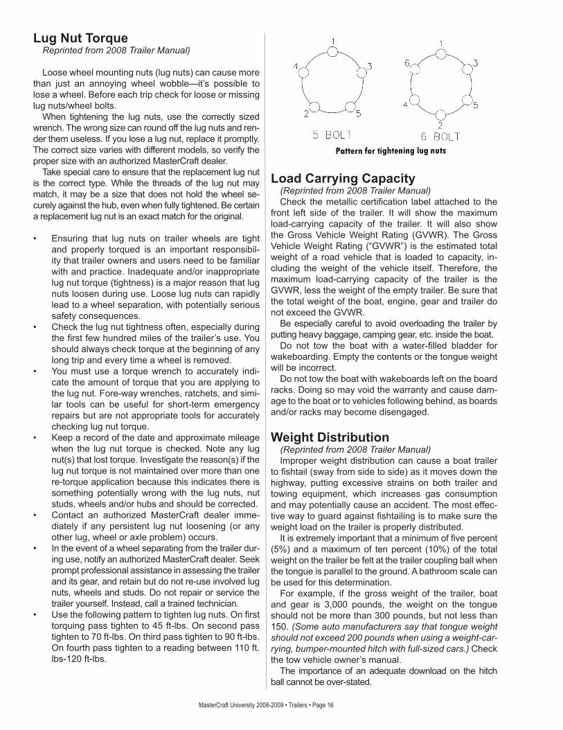
• Usethefollowingpatterntotightenlugnuts.Onfirsttorquingpasstightento45ft-lbs.Onsecondpasstightento70ft-lbs.Onthirdpasstightento90ft-lbs.Onfourthpasstightentoareadingbetween110ft.lbs-120ft-lbs.
MasterCraft University 2008-2009 • Trailers • Page 16

Oil Bath ComparisonsI. Purpose: Todeterminewhichoilisbestsuitedtobeused
withtheReliableOilBathLubricationSystem.
II. Test Conditions: AReliableUHIidlerunitwasequippedwiththe
ReliableOilBathusingtheplasticscrew-instylecap.SAE50WmotoroilandSAE80W-90gearoilwereusedforcomparison.Waterwasinten-tionallyinducedtodeterminewhichoilresistedmixingwiththewaterandhowtherunningtem-peratureofthehubwasaffected.
III. Test Results: TheSAE50Wmotoroilwastestedfor12840
milesat60mph.Midwaythroughthetest1ounceofwaterwasinduced.Theaveragetem-peratureofthehubwas103.0°priortoaddingthewaterandwentuptoanaveragerunningtemperatureof115.5°afterinducingthewater.Theoilturnedtoamilkycolorwhenthewaterwasinduced.
TheSAE80W-90gearoilwastestedfor10020milesat60mph.Midwaythroughthetest1ounceofwaterwasinduced.Theaveragetem-peratureofthehubwas107.6°priortoaddingthewaterandwentuptoanaveragerunningtemperatureof117.6°afterinducingthewater.Theoilturnedtoamilkycolorwhenthewaterwasinduced.
IV. Conclusion: Bothoilsperformedequallyandprovidedno
advantageswitheitherheatortheabilitytoresistmixingwiththewater.
Oil Bath Lubrication System– Frequently Asked QuestionsQuestion:The oil has turned dark with minimal us-
age, is this normal?Response: Yes,theoilwillturndarkerwithuseand
starttoturndarkwithminimaluse.Con-tinuetoruntheunitwithoutperforminganymaintenance.
MasterCraft University 2008-2009 • Trailers • Page 17
Question: The oil looks milky or has turned a lighter color?
Response: Moisturehasenteredthesystematsomepoint.Drainandreplacetheoilwithnewandwatchtheunitclosely.Inmanyinstancestheunitwillperformproperlywithoutperforminganyadditionalmainte-nance.Iftheproblemreoccurs,replacetherearsealandtheoilbathcapando-ringusingtheproperproceduresasoutlinedinthemaintenancemanual.
Question: What type of oil do you recommend?Response: SAE50Woilisrecommended.80W-90
gearoilisalsoasuitablereplacementandcanbemixedwithoutissue,althoughitisrecommendedtheoldoilbedrainediftheoilsaretobemixed.
Question: How do I add or drain the oil?Response: Thereisafillplugontheoutsideofthe
hubthatcanberemovedtofillordraintheoil.Insomecases,thewheelwillneedtoberemovedinordertogettotheplug.
Question: How do I know how much oil to put in and how do I know when to add oil?
Response: TheoillevelshouldbefilledtothetopoftheReliablelogoasoutlinedinthemain-tenancemanual.Oilshouldbeaddedanytimetheoillevelgetsbelowhalffull.Thislevelcanbeclearlyseenthroughtheclearportionontheendoftheoilbathcap.
Question: How tight do I tighten the fill plug?Response: Thefillplugshouldbetightenedsnugly
usingastandard3/16”Allenwrench.Theplugismadeofbrasssoover-tighteningcandistortthehexmakingitdifficulttoremoveatalatertime.
Question: How do I remove the cap if mainte-nance has to be performed and how tight should the cap be retightened?
Response: Thecapisscrewedinandcanberemovedbyturningthecapinthecounter-clockwisedirection.Thecapshouldbetightenedto25-30ft./lbs.whenre-installed.