trailing edge treatment to enhance high lift system
TRANSCRIPT

28TH
INTERNATIONAL CONGRESS OF THE AERONAUTICAL SCIENCES
1
Abstract
A quasi two-dimensional experimental and
numerical investigation was performed to
determine the effect of different trailing edge
treatment on the performance of a two-element
high lift wing. Two trailing edge treatments
were used in both main element and flap: a saw-
tooth trailing edge and Gurney Flap and a
combination of both. The saw-tooth trailing
edge consisted of triangles, wishbone and
trapezoidal formats applied to the trailing edge
of the wing main element of in order to promote
mixing between the higher-pressure flow from
the lower surface with the flow on the upper
surface. The Gurney flap was a flat plate on the
order of 1 to 4% of the airfoil chord in length,
oriented perpendicular to the chord line and
located on the airfoil windward side at the
trailing edge. The flow field around the airfoil
was numerically predicted using CFX, with non-
linear RANS turbulence model. The results from
both numerical and experimental work show
that the serrated trailing edge can improve the
flow over the flap by delaying turbulent
separation consequently decreasing pressure
drag. Also, Gurney flaps increase the airfoil lift
coefficient with an increase in drag coefficient.
The combination of both serrated trailing edge
and Gurney flap can lead to a higher
performance high lift wing especially for the
take-off configuration.
1 Introduction
One of the most effective devices to
increase wing lift is the trailing edge flap. With
the flap it is possible to produce more lift for the
same incidence angle and at a lower velocity,
enhancing take-off and landing performance.
For take-off it is also important to increase the
maximum wing CL that is not always achieved
with a flap. Therefore, sometimes a slat or
leading edge flap is also necessary. Single flaps
have difficulty producing a considerable
increase on CLmax mainly due to the turbulent
separation on the suction surface. Higher
performance can be achieved by using multi-
element fowler flaps but their mechanisms are
complex and heavy. The ideal flap would be a
single element fowler flap, which could produce
high maximum CL with a low boundary layer
pressure drag penalty. With this kind of flap, in
some cases, the leading edge high lift devices
would be not necessary. The use of vortex
generators is widely employed in aeronautical
engineering to reduce turbulent separation on
the wing and reduce pressure drag. The effect of
vortex generators on wing performance was first
studied by Taylor [1] in 1945. However, in
general, vortex generators are not practical at
cruise speeds and also produce parasite drag
[2.3]. Also, it is not easy to locate vortex
generators at the flap upper surface in order to
inject enough turbulence into the boundary layer
due to the lack of space between main element
and flap in the stowed position. Novel trailing
edges have been proposed by Werle et al [4] in
order to alleviate separation on airfoils and
wings. This consists on waving the trailing edge
in order to promote mixing between the higher-
pressure flows from the lower surface with the
flow on the upper surface. This mixing reduces
wing trailing edge separation increasing
maximum lift values. For the case of a wing
main element and flap waving the main element
trailing edge would make flap stowing
impossible. This work proposes to use a similar
TRAILING EDGE TREATMENT TO ENHANCE HIGH LIFT SYSTEM PERFORMANCE
Catalano F.M.*, Ceròn E.D.* Greco P.C.
* Laboratory of Aerodynamics EESC-USP Brazil
[email protected];[email protected],[email protected]
Keywords: high lift, serrations, Gurney flap

CATALANO F.M, CERÓN H.D., GRECO P.C.
2
method of mixing flow at the trailing edge by
adopting a saw tooth trailing edge rather than
using waves. There have been quite a number of
works on the Gurney flap since the race driver
Dan Gurney used this flap on the inverted wing
of his car, increasing down force, in the 60’s.
Despite this fact, the use of Gurney flaps still
almost restricted to race cars with little use in
aircraft design mainly due to the increase in
drag that may occur especially in cruise
conditions. However, the demands for a high lift
system that could be at same time highly
efficient and with a minimum complexity, has
brought attention back for the use of Gurney
flap on multi elements wings. Numerous wind
tunnel tests on Gurney flaps have been
conducted in both single and multi-element
airfoils of 2-D and 3-D wings. Giguerre et al [6]
presents an extensive list of these works. The
first work concerning Gurney flaps was carried
out by Liebeck [5] who found that lift is
increased with the attachment of a Gurney flap
at the trailing edge of airfoils. Liebeck also
found that drag increases but for Gurney flaps
with a height below 2% of the chord a slight
decrease in drag can occur. For Gurney flap
heights beyond 2% drag penalty may be
prohibitive even if overall L/D increases. A
parametric study of the application of Gurney
flaps on a single and multi-element three-
dimensional wing was carried out by Moyse and
Heron [7]. Moyse and Heron found that the
Gurney flap increased lift for the majority of the
configurations tested with a drag penalty
dependent of the Gurney flap height. They also
founded that placing a Gurney flap at the
trailing edge of the main element; in general
there is no significant improvement in the wing
performance mainly due to the change in the
gap of the slotted flap. On the other hand, Ross
et all [8] demonstrated experimentally and
computationally that placing a Gurney flap on
both flap and near the trailing edge of the main
element can achieve an increase in lift of 12%
and 40% on the lift to drag ratio. The range of
Gurney flap heights tested was from 0.125 to
1.25% of the airfoil reference chord. Ross et al
[8] positioned the Gurney flap at 0.5% chord
upstream of the trailing edge of the main
element rather than right at the trailing edge.
This allowed the Gurney flap to be retracted
when the high lift system is stowed. Intensive
computation analysis was performed by Jang et
al [9] and Carrannanto [10] in order to
investigate the effect of the Gurney flap on an
airfoil by using an incompressible Navier-
Stokes solver with the one-equation turbulence
model of Baldwin and Barth. The numerical
data was compared with experimental data
available in order to validate the computational
flow visualization in the Gurney flap region.
The general conclusion on the effect of the
Gurney flap on the local flow is the production
of a pair of counter rotating vortices
downstream of the trailing edge. These vortices
act like an airfoil extension, increasing the
effective chord and camber. In this sense, it is
expected that the Gurney flap at the main
element trailing edge region will change the
flow inclination in order to alleviate flap
adverse pressure gradient and thus delaying
separation. Delaying flap separation is good
news for the high lift system in the climb
configuration but is not necessarily welcome for
landing when drag is also necessary. Unless the
Gurney flap is of the retracted type as suggested
by Ross et al [8] the use of this device will not
be directly applicable in aircraft design before a
trade-off analysis. An alternative to solve this
problem is to use a different device at the main
element trailing edge that would delay flap
separation in the climb configuration but would
be less effective at high flap angles such as in
landing configuration. Lemes and Catalano [11]
proposed a serrated trailing edge that promotes
mixing between the higher-pressure flow from
the lower surface with the flow on the upper
surface to produce vortices. These vortices feed
high momentum and low turbulent kinetic
energy flow into the flap boundary layer
delaying separation. A serrated main element in
conjunction with a flap with Gurney flap could
create a high lift system that would bring
benefits to both take-off/climb and
approach/landing. In this work, application of
the Gurney flap at the trailing edge of a slotted
flap in a quasi-two-dimensional two element
wing is analyzed experimentally and
numerically. Also, a serrated main element
trailing edge of the same wing is analyzed in

3
TRAILING EDGE TREATMENT TO ENHANCE HIGH LIFT SYSTEM PERFORMANCE
order to find the potential benefit of applying
both systems in a high lift wing.
2 Experimental Set-up
The experiment was conducted in the Wind
tunnel of Aerodynamic Laboratory of Sao
Carlos Engineering School, University of Sao
Paulo. The Wind tunnel is closed circuit and
closed working section, the height dimensions
of which are: 1.75m width, 1.30m height and
4m length. Turbulence level and maximum
velocity are 0.20% and 50m/s respectively. The
wing model has two elements with a flap and
main element as showing in Fig. 1. The flap and
main element are made of fiberglass with steel
spars fixed to circular end plates to simulate a
two-dimensional wing. The main dimensions of
the wing are in Table 1. Using end plates does
not assure two-dimensional flow, especially in
high lift wings such as this model. However, at
the center of the wing, where chordwise
pressure measurements are performed the three-
dimensional flow induced by the secondary
vortices at the end plate is minimal. Also, the
comparative analysis of this work assumes that
any secondary vortex effect at the center of the
wing will be present in both configurations:
with and without the trailing edge treatment.
The flap incidence angle can be changed but
within a small range due to the subsequent
change in the wing/flap gap and overlap. A total
of 90 chordwise pressure taps were used to
measure pressure coefficient distribution on
both surfaces of the wing main element and
flap. The pressure coefficient distributions were
measured by two mechanical D48 scanivalves
fitted with ± 1.0-psia setra transducer. The wing
was positioned in a vertical position attached to
the aerodynamic balance below the tunnel floor
(Fig.. 2). The aerodynamic balance has only two
components so that drag and side force (lift)
were measured for a range of incidence angle of
–4o to 20o. The two-component balance used is
of the strain gage type and has a measurement
accuracy of ± 0.7% for maximum loading.
Therefore, accuracy for Lift and Drag are ±1.0N
and ±0.19N respectively. Incidence angle was
measured with an accuracy of ±0.1 deg.
Fig.. 1 Wing model.
Tab 1: Model wing Main dimensions.
Main Element Flap
Reference area 0.399 m2 0.396 m2
Span 1.00 m 1.00 m
Chord 0.186 m 0.170 m
Fig. 2 Experimental set-up.
A series of saw-tooth plywood strips were
glued to the trailing edge of the main element.
The saw tooth geometry was defined by the size
of the tooth and the distance between each of
them. Fig. 3 shows the dimensions of trailing
edge serrations. The saw tooth trailing edge
changes the gap and overlap between main
element and flap in comparison with the clean
wing. Therefore, the clean wing case was tested
with an increase of the longitudinal trailing edge
dimension of 2% and 3% of the main element
chord in order to assure the same gap and
overlap of the wing with the saw tooth trailing
edge. Previous results [5,6 and 7] suggest that

CATALANO F.M, CERÓN H.D., GRECO P.C.
4
Gurney flap with heights of less than 5% of
airfoil chord may produce less drag penalty.
Therefore, in this work only the Gurney flaps of
heights of 1%, 2% and 4% of reference chord
were used in the tests. The experiments were
conducted at an average Reynolds number of
400.000 and no trip wire or roughness strip was
attached on the leading edge so that transition
was free and laminar bubbles were expected to
occur.
Fig. 3 Trailing edge serration dimensions.
The confluent boundary layer and shear layer
between main element and flap was measured
using a single hot wire probe positioned in 465
points in a plane at 0.25% downstream of the
flap leading edge as shown in Fig. 4. Boundary
Layer transition was also investigated through
flow visualization with the sublimation
technique.
Fig. 4 Mapping grid of the hot wire
anemometry measurements.
2.1 Numerical Set-up
The computer program used was the Ansys
CFX with its auxiliary software for grid
generation the ICEM CFD 5.0, and CFX-
Pre/Pos 5.7 for pre-processing and pos-
processing. The computational domain adopted
has exactly the wind tunnel working section
dimensions: 1.3m x 1.75m with a length
sufficiently long in order to not be affected by
the presence of the wing model and simulate the
working section flow. Also, the computational
domain length was the shortest for the least
computational cost. The non-structured mesh of
the computational domain and model are shown
in Fig. 5. Details of the wing and end-plate
non-structured mesh can be seen in Fig. 6. One
of the main objectives of the numerical work
was to analyze the region of the Gurney flap and
the effect that this element imposes on the
whole model. In the above mentioned region,
flow separation is likely to occur thus, it was
decided to apply the k-ε turbulence model
which is a non-linear Reynolds Averaged
Navier-Stokes model (RANS). The main
advantage of this formulation is that it simulates
with more accuracy the phenomena and has less
computational cost compared with LES (Large
Eddy Simulation) and DNS (Direct Numerical
Simulation).
Fig. 5 Computational domain and model.
Fig. 6 Unstructured grid for the two element
wing with Gurney flap and end-plate.

5
TRAILING EDGE TREATMENT TO ENHANCE HIGH LIFT SYSTEM PERFORMANCE
3 Results and Discussion
The results are presented and discussed
separately for serrated trailing edge and Gurney
flap set-ups. The numerical investigation was
carried out for the Gurney flap in order to
understand the flow at that part of the wing, as
well as, the flow mapping was carried out only
for the main element and flap slot flow.
3.1 Serrated trailing edge
During the tests was decided to use two
different sizes for the triangular serrations. The
Tri 3% and Tri 5% the triangle high is 3% and
5% of the main element chord respectively.
Figures 07 and 08 show the effect of the saw-
tooth trailing edge mixing on the flap separation
as well as on its suction peak. The increase of
attached flow was approximately 20% and 46%
for the Tri3% and Tri5% respectively for the
range of wing incidence angles higher than
8deg. For low incidence the effect is more
intense only for the Tri5% and there is also an
increase on the flap suction peak as shown in
Fig. 7. However, for the entire range of
incidence angles tested there was an increase in
suction on the downstream end of the wing
main element, showing that there was an
improvement on tangential velocity in that
region. This effect combined with the injection
of turbulence on the flap boundary layer may
improve flap aerodynamic performance. These
effects did not affect the laminar separation
bubble located at the wing main element upper
surface. The laminar separation bubble is shown
in Figs. 8 and 9 by the letters LS (laminar
separation), T (transition) e TR (turbulent
reattachment). For low incidence angles and
flap at 4deg the effect of the saw-tooth trailing
edge also appears as a global increase of
circulation. This effect can be confirmed in Fig.
10 by the increase of suction and pressure on the
upper and lower surface of the front part of the
wing main element respectively. From the
analysis of the previous results it is clear that the
effect of the saw-toothed trailing edge depends
on the wing geometry, gap and overlap and saw-
tooth geometry and that a proper saw-toothed
trailing edge must thus be designed for each
new wing. The hot wire mapping measurements
showed very interesting results in both the
confluent boundary layer and at the flap surface.
Comparing the cases with and without the saw-
toothed trailing edge in Figures 11 to 15 it can
be seen that there is an intermittent vortex
formation on the saw-tooth that injects
turbulence and energy into the flap boundary
layer as the tangential speed at the flap surface
also increases. The tendency is for downstream
mixing-up of this stratification to occur which
affects beneficially the turbulent separation.
Figures 16 and 17 show the velocity profile at
the serration vertex and between two serration
teeth (y=0 is not at the wall). It is clear from
Fig. 16 that the vortices pair formed at the
serration induces a downwash to the main
element wake increasing the near the flap
surface velocity. Fig. 17 shows the same
increase of the velocity near the flap surface as a
turbulent boundary layer profile. This effects
discussed above can explain the improvement of
the flap aerodynamics although, the
optimization between gap, overlap and serration
geometry must be carried out in order to get best
results. The sublimation technique is used to
detect the transition front as the naphthalene
sublimes under turbulence, in this way the
results of Fig. 18 shows that laminar flow has
increased but this effect occurs due to the
stratified flow pattern generated by the saw-
toothed trailing edge where there are transition
spots and laminar flow forming a “zigzag”
transition front. The results from mapping the
flow just behind the saw-tooth trailing edge
showed that there remains a field for the of
study different geometries for the saw-tooth in
order to produce a better interaction between the
vortices generated and the flow from the
wing/flap gap of any other format. Fig. 19
shows the pattern of oil flow visualization for
the trapezoidal serration. The quite complex
flow created between the vortices and the
laminar separation bubble at the flap surface
may be the key for the downstream movement
of the separation front.

CATALANO F.M, CERÓN H.D., GRECO P.C.
6
Fig. 7 Cp vs. x/c for α=0o and
flap angle at 8
o.
Fig. 8 Cp vs. x/c for α= 10o and flap at 8
o.
Fig. 9 Cp vs. x/c at α=20o and flap at 8
o.
Fig. 10 Velocity topography of clean wing α =
10o flap at 12
o.
Fig. 11 Velocity topography for Tri3% for α
= 10o flap at 12
o.
Fig. 12 Velocity topography for Tri5% α =
10o flap 12
o
Mainelement
flap
Tri 5%
Tri 3%
Clean
Mainelement
flap
LS
T
R
Tri 5%
Tri 3%
Clean

7
TRAILING EDGE TREATMENT TO ENHANCE HIGH LIFT SYSTEM PERFORMANCE
Fig. 13 3-D velocity distribution of airfoil
with Tri3% at α = 10o and flap at 12
o.
Fig. 14 3-D velocity distribution of airfoil
with Tri5% at α = 10o and flap at 12
o.
Fig. 15 Velocity profiles at serration vertex,
α=10o, flap at 12
o.
Fig. 16 Velocity profile between serrations,
α=10o flap at 12
o.
Fig. 17 Visualization using naphthalene over
flap upper surface α = 10o, flap at 12
o.
Fig. 18 Oil flow visualization α=4o flap at 12
o.
3.2 Gurney Flap
The results for pressure coefficient are presented
always in comparison between the three Gurney
flaps and the wing without Gurney flap. Figures
19 to 22 presents the results for incidence angles
of: 0o, 8
o and 16
o with the Gurney flap installed
at the trailing edge of the flap set at a flap angle
of zero degrees. For this wing the flap at zero
degree means that the flap is in the design
position. For all the experimental results it is
clear that the Gurney flap increases effective
camber as can be seen in Figs 20 to 22, in which
Laminar separationbubble
CATALANO F.M, CERÓN H.D., GRECO P.C.
8
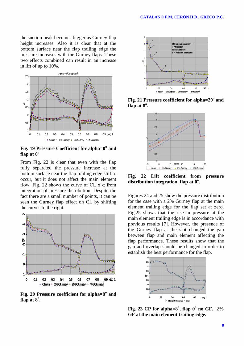
the suction peak becomes bigger as Gurney flap
height increases. Also it is clear that at the
bottom surface near the flap trailing edge the
pressure increases with the Gurney flaps. These
two effects combined can result in an increase
in lift of up to 10%.
Fig. 19 Pressure Coefficient for alpha=0o and
flap at 0o
From Fig. 22 is clear that even with the flap
fully separated the pressure increase at the
bottom surface near the flap trailing edge still to
occur, but it does not affect the main element
flow. Fig. 22 shows the curve of CL x α from
integration of pressure distribution. Despite the
fact there are a small number of points, it can be
seen the Gurney flap effect on CL by shifting
the curves to the right.
Fig. 20 Pressure coefficient for alpha=8o and
flap at 8o.
Fig. 21 Pressure coefficient for alpha=20o and
flap at 8o.
Fig. 22 Lift coefficient from pressure
distribution integration, flap at 0o.
Figures 24 and 25 show the pressure distribution
for the case with a 2% Gurney flap at the main
element trailing edge for the flap set at zero.
Fig.25 shows that the rise in pressure at the
main element trailing edge is in accordance with
previous results [7]. However, the presence of
the Gurney flap at the slot changed the gap
between flap and main element affecting the
flap performance. These results show that the
gap and overlap should be changed in order to
establish the best performance for the flap.
Fig. 23 CP for alpha=8o, flap 0
o no GF. 2%
GF at the main element trailing edge.
Alpha = 0
o, Flap at 0
o
-2.5
-2
-1.5
-1
-0.5
0
0.5
1
0 0.1 0.2 0.3 0.4 0.5 0.6 0.7 0.8 0.9 1X/C
CP
Clean 1% Gurney 2% Gurney 4% Gurney
-5
-4
-3
-2
-1
0
1
0 0.1 0.2 0.3 0.4 0.5 0.6 0.7 0.8 0.9 1X/C
CP
Clean 1% Gurney 2% Gurney 4% Gurney
-6
-5
-4
-3
-2
-1
0
1
0 0.2 0.4 0.6 0.8 1X/C
CP
Clean 1% Gurney 2% Gurney 4% Gurney
S
LS
T
R
LS= laminar separation
T = transition
R = reatachment
S = Turbulent separation
0
0.5
1
1.5
2
2.5
3
3.5
-5 0 5 10 15 20alpha
CL
clean 1% Gurney 2% Gurney 4% Gurney
-3
-2.5
-2
-1.5
-1
-0.5
0
0.5
1
0 0.2 0.4 0.6 0.8 1X/C
CP
GFmain2% flap crean Clean

9
TRAILING EDGE TREATMENT TO ENHANCE HIGH LIFT SYSTEM PERFORMANCE
Fig. 24 Cp for α=8o, flap at 8
o 2% Gurney
flap at the main element and flap.
3.3 Numerical Results
The numerical results are presented in Fig. 25
with respect to the comparison with
experimental pressure distribution.
Computational results have failed to reproduce
with accuracy the complex flow exiting in this
particularly wing. Although suction peaks are at
same level, the numerical calculation did not
predicted well the large laminar separation
bubble existing at all incidence angle mainly
due to the low Reynolds number of the
experiment (0.4x10⁶) and the airfoil leading
edge geometry which would induce laminar
separation bubble. At the flap there was another
problem with the position of the suction peak
and the separation point, probably due to the
numerical solution of the confluent boundary
layer created by the main element wake.
However, computation results were used to
identify points of interest in the flow around the
wing such the Gurney flap area. Figs 26 to 29
show results by using the computational flow
visualization. The area of interest shown in Fig.
26 is that at the flap trailing edge with the 4%
Gurney flap. The incidence angle is 8deg with
the flap at zero deg. Fig. 27 shows the two
counter rotating vortices and these results are in
agreement with previous works [8, 9 and 10]. It
is clear from Fig 27 the different scale of the
two vortices making a downward movement of
the flow that is leaving the upper surface at the
trailing edge. This downward movement in
conjunction with the existence of a vortex wake
body displaces the stagnation point (or effective
Kutta point) as it can be seen in Fig. 27 thus
increasing effective camber and chord. The
same computational procedure was applied to
the case of serrated trailing edge in order to
visualize the flow at the flap gap. Figure 27
shows the results for the Tri5% serration. It can
be seen from these results the vortices and the
effect on the flap surface in a similar pattern of
the mapping experimental results at that region.
Fig. 25 Comparison with numerical results,
alpha = 8o flap at 0o, 1% Gurney flap.
Fig. 26 Definition of the area of investigation
at the Gurney flap region.
Fig. 27 Downstream and downward
displacement of the Kutta point.
Fig. 28 Flow at the serration flap at 0o.
-5
-4
-3
-2
-1
0
1
0 0.2 0.4 0.6 0.8 1
X/C
CP
Gf main2% main clean 5% Gurney Clean -4
-3
-2
-1
0
1
0 0.2 0.4 0.6 0.8 1X/C
Cp
Cp - Experimental Cp - Computacional

CATALANO F.M, CERÓN H.D., GRECO P.C.
10
4 Conclusions
An experimental and numerical study was
carried out in order to evaluate the potential
benefit of trailing edge treatment on the
aerodynamic characteristics of a high lift wing
with a single slotted flap. It were evaluated the
effect of a saw-toothed trailing edge of a main
wing on the aerodynamic performance of a
single flap and the application of Gurney Flaps
of different height at the trailing edge of the
flap. The results showed that vortices is formed
at the saw-toothed trailing edge through the
mixing between the flow from the pressure side
to the suction side at the main wing and flap
gap. This vorticity is injected inside the flap
boundary layer delaying separation. However,
the generalization of these results depends on
new experimental tests with a wing/flap model
that could change gap and overlap. Performing
such tests, the relationship between saw-toothed
trailing edge geometry and the gap and overlap
could be optimized. It was used three Gurney
flap heights 1%, 2% and 4% of the reference
chord. The results showed that the Gurney flap
positioned at the flap trailing edge can increase
lift for most of the incidence tested. The Gurney
flap is less effective when large turbulent
separation occur at the flap and main element.
The use of Gurney flap at the trailing edge of
the main element is highly dependent on the gap
and overlap optimization. The numerical
simulation using k-є turbulence model which is
a non-linear Reynolds Averaged Navier-Stokes
model (RANS) did not predicted accurately the
pressure distribution. However, with more grid
adjustment and refinement good results could be
achieved. Numerical simulation of the flow at
the region where the Gurney flap was installed
was qualitatively very important to explain the
effect of the Gurney flaps. The low cost and
mechanical installation simplicity allied with its
significant impact on aerodynamic performance
make the Gurney flap a very attractive device to
be used in subsonic aviation.
5 References
[1] Storms B L and Jang C S. Lift enhancement of an
airfoil using a gurney flap and vortex generators.
Journal of Aircraft. Vol. 31. No. 3. pp 542-547. 1994.
[2] Taylor H D. The elimination of diffuser separation by
vortex generators. United Aircraft Corp.. R4012-3.
East Hartfort. CT. 1947.
[3] Rao D M and Kariva T T. Boundary-layer submerged
vortex generators for separation control, An
exploratory study. Proceedin of the 1st
National Fluid
Dynamics Conference. Cincinati OH. AIAA.
Washington. DC. pp. 839-846. 1988.
[4] Werle, M. J. and Paterson, W. M. Trailing-edge
Separation/Stall Alleviation. AIAA Journal Vol 25,
No. 4 April 1987.
[5] Liebeck, R. H. (1978), Design of Subsonic Airfoils
for High Lift, Journal of Aircraft, Vol 15, No. 9, pp.
547-561.
[6] Giguere P., Lemay, J., and Dumas, G., Gurney Flap
Effect and Scalling for Low Speed Airfoils, AIAA
Paper 95-1881, Jun.1995
[7] Myose R., Papadakis M. and Heron Ismael, A
Parametric Study on the Effect of Gurney Flaps on
Single and Multi-Element Airfoils, Three-
Dimensional Wings, and Reflection Plane Model.
AIAA 97-0034, 35th
Aerospace Science Meeting &
Exhibit 1997, Reno Nevada USA
[8] Ross JC, Storms BL, Carrannanto PC. Lift-enhancing
Tabs on Multi-element Airfoils. Journal of Aircraft
1995; Vol 32 No3 649-655.
[9] Jang C. S., Ross J. C., Cummings R. M. Numerical
investigation of an airfoil with a Gurney flap, Aircraft
Design Vol1 (1998) 75-88
[10] Carrannanto P. G., Storms B. L., Ross J. C.,
Cummings R. M., Navier-Stokes Analysis of Lift-
Enhancing Tabs on Multi-Element Airfoils, Aircraft
Design Vol 1 (1998) 145-158
[11] Lemes, R.C., Catalano, F.M. Experimental Analysis
of the Confluent Boundary Layer Between a Flap and
a Main Element with Saw-Toothed Trailing Edge,
24th International Congress of the Aeronautical
Sciences ICAS 2004, Yokohama Japan.
Copyright Statement
The authors confirm that they, and/or their company or
organization, hold copyright on all of the original material
included in this paper. The authors also confirm that they
have obtained permission, from the copyright holder of
any third party material included in this paper, to publish
it as part of their paper. The authors confirm that they
give permission, or have obtained permission from the
copyright holder of this paper, for the publication and
distribution of this paper as part of the ICAS2012
proceedings or as individual off-prints from the
proceedings.