train order working and electronic authority – advanced ... · train order working and electronic...
TRANSCRIPT

Division / Business Unit: Enterprise Services Function: Engineering (Signalling) Document Type: Standard
© Australian Rail Track Corporation Limited (ARTC)
Disclaimer
This document has been prepared by ARTC for internal use and may not be relied on by any other party without ARTC’s prior written consent. Use of this document shall be subject to the terms of the relevant contract with ARTC.
ARTC and its employees shall have no liability to unauthorised users of the information for any loss, damage, cost or expense incurred or arising by reason of an unauthorised user using or relying upon the information in this document, whether caused by error, negligence, omission or misrepresentation in this document.
This document is uncontrolled when printed.
Authorised users of this document should visit ARTC’s intranet or extranet (www.artc.com.au) to access the latest version of this document.
Page 1 of 56
Train Order Working and Electronic Authority – Advanced Train Management System ESD-08-01
Applicability
ARTC Network Wide
Publication Requirement
Internal / External
Primary Source
SDS 19
Document Status
Version # Date Reviewed Prepared by Reviewed by Endorsed Approved
1.6 07/12/2016 Standards Stakeholders Manager Standards
General Manager Technical Standards 23.12.2016
Amendment Record
Amendment Version #
Date Reviewed
Clause Description of Amendment
1.0 27 Apr 09 First issue. Supersedes NSW Standard SDS 19 v2.0
1.1 07 Oct 09 Disclaimer updated as per Risk & Safety Committee 14/09/2009
1.2 13 Aug 10 All Issued as final.
1.3 11 Oct 11 Changes for TOW network control boundaries 1.1.12, 1.8, 1.2.2 and alternate points track circuits 1.3.3.

Train Order Working and Electronic Authority – Advanced Train Management System
ESD-08-01
Table of Contents
This document is uncontrolled when printed. Version Number: 1.6 Date Reviewed: 07/12/2016 Page 2 of 56
Update to 1.3.3 to delete reference to high voltage impulse type track circuits following endorsement from OS&ERG 11/10/11.
1.4 30 Aug 13 1, 2.13, 2.14, 2.19, 3.9, 4.3 & 5.3 Changes for PTOS Operation and Format Update.
1.5 31 Jul 14 1.3 & 1.5 Minor editorial update to delete blank definitions table and add SFAIRP definition in text.
1.6 07 Dec 16 1.1, 1.2, 1.4, 2, 2.1, 2.2, 2.3, 2.4, 2.5, 2.6, 2.8, 2.9, 2.10, 2.11, 2.15, 2.16, 2.17, 2.18, 2.19, New section 4, 11, 11.1, 11.4.2, 11.5
Addition of Electronic Authority – Advanced Train Management System updates to various sections and new section 4. Minor amendments to original standard due to clerical and diagram issues. Also updated to include items from the Issues Register and updates to reflect naming conventions within the CoP.

Train Order Working and Electronic Authority – Advanced Train Management System
ESD-08-01
Table of Contents
This document is uncontrolled when printed. Version Number: 1.6 Date Reviewed: 07/12/2016 Page 3 of 56
Table of Contents
Table of Contents ............................................................................................................................................. 3
1 Introduction ............................................................................................................................................. 7
1.1 Purpose .......................................................................................................................................... 7
1.2 Scope ............................................................................................................................................. 7
1.3 Responsibilities .............................................................................................................................. 7
1.4 ARTC Reference Documents ......................................................................................................... 8
2 Train Order Working and Electronic Authority – Advanced Train Management System Infrastructure .......................................................................................................................................... 9
2.1 Introduction to TOW ....................................................................................................................... 9
2.2 Introduction to Electronic Authority – Advanced Train Management System ................................ 9
2.3 Location Ahead Sign ...................................................................................................................... 9
2.4 Yard Limit Signs ........................................................................................................................... 10
2.5 Shunt Limit Signs ......................................................................................................................... 10
2.6 Clearance Posts/Control Point ..................................................................................................... 11
2.7 Point Indicators............................................................................................................................. 12
2.7.1 Mechanical – Main line usage ...................................................................................................... 12
2.7.2 Electrical ....................................................................................................................................... 13
2.8 Points Setting Indicator ................................................................................................................ 13
2.8.1 Point Indicators - not on the main line .......................................................................................... 14
2.9 Main Line Indicators/Repeaters ................................................................................................... 14
2.10 Light Indicators ............................................................................................................................. 16
2.11 “Start” or “Begin Train Order Working” Sign ................................................................................ 17
2.12 “Begin ATMS Working” sign ......................................................................................................... 18
2.13 “End Train Order Working” sign ................................................................................................... 18
2.14 “End ATMS Working” sign ............................................................................................................ 19
2.15 Network Control Boundary Location signs ................................................................................... 19
2.16 Ground Frames ............................................................................................................................ 20
2.17 Operating Keys............................................................................................................................. 20
2.17.1 Operators Key .............................................................................................................................. 20
2.17.2 Master Key ................................................................................................................................... 21
2.17.3 Inspection Key .............................................................................................................................. 21

Train Order Working and Electronic Authority – Advanced Train Management System
ESD-08-01
Table of Contents
This document is uncontrolled when printed. Version Number: 1.6 Date Reviewed: 07/12/2016 Page 4 of 56
2.17.4 Safes for Keys .............................................................................................................................. 21
2.18 Landmarks .................................................................................................................................... 21
2.19 Shunting Limit or Stop Signs ........................................................................................................ 22
2.20 Block Location Name Signs ......................................................................................................... 22
2.21 Train Order and Electronic Authority – Advanced Train Management System Kilometrage Signs22
2.22 Derailers ....................................................................................................................................... 23
3 Types and Layout of Train Order Locations ...................................................................................... 24
3.1 Introduction ................................................................................................................................... 24
3.2 Types of Train Order Locations - NSW ........................................................................................ 24
3.3 Mechanical Point Indicators (MPI) ............................................................................................... 26
3.4 Main Line Indicators (MLI) ............................................................................................................ 26
3.5 Repeaters to Main Line Indicators ............................................................................................... 27
3.6 Closely Spaced Train Order Locations ........................................................................................ 27
3.7 Provision of Additional Main Line Indicators within Train Order Locations .................................. 29
3.8 Naming of Ground Frames at Train Order Locations .................................................................. 29
3.9 Locking of Derailers at Train Order Locations ............................................................................. 30
4 Layout of Electronic Authority – Advanced Train Management System........................................ 31
4.1 Introduction ................................................................................................................................... 31
4.2 Entering Electronic Authority – Advanced Train Management System territory .......................... 31
4.2.1 Mapped Track ............................................................................................................................... 31
4.2.2 Mapped Track Sign....................................................................................................................... 31
4.2.3 Entrance and exit track circuit ....................................................................................................... 32
4.3 Control Point................................................................................................................................. 32
4.4 Crossing Loop Provided ............................................................................................................... 32
4.5 Track Locking ............................................................................................................................... 33
4.5.1 Types of track circuits used for Track Locking .............................................................................. 33
4.5.2 Extent of Track Circuit Locking ..................................................................................................... 33
4.6 Point Setting ................................................................................................................................. 33
4.7 Operating Points from Local Control ............................................................................................ 34
4.8 Operation of Points from AMS ..................................................................................................... 34
4.9 Light Indicator ............................................................................................................................... 35
4.10 Repeaters to Light Indicator ......................................................................................................... 35
4.11 Shunt Limit Signs ......................................................................................................................... 35
5 Train Order Locations with Motorised Points ................................................................................... 36

Train Order Working and Electronic Authority – Advanced Train Management System
ESD-08-01
Table of Contents
This document is uncontrolled when printed. Version Number: 1.6 Date Reviewed: 07/12/2016 Page 5 of 56
5.1 Introduction ................................................................................................................................... 36
5.2 General Arrangement ................................................................................................................... 36
5.3 Track Locking ............................................................................................................................... 36
5.3.1 Types of track circuits used for Track Locking .............................................................................. 36
5.3.2 Extent of Track Circuit Locking ..................................................................................................... 37
5.4 Point Setting ................................................................................................................................. 37
5.5 Emergency Operation of Points ................................................................................................... 37
5.6 Use of Repeating Indicators ......................................................................................................... 37
6 Level Crossings at Train Order Locations ......................................................................................... 38
6.1 Introduction ................................................................................................................................... 38
6.2 Arrangement where the Level Crossing is some distance from the Loop/Siding ........................ 38
6.3 Arrangement where the Level Crossing is close to the Loop/Siding ........................................... 39
6.4 Arrangement with Sidings on each side of the Level Crossing .................................................... 40
6.5 Specific Provisions for Passenger or Stopping Trains ................................................................. 41
6.6 Level Crossings at Locations Equipped with Main Line Indicators .............................................. 41
7 Junctions at Train Order Locations.................................................................................................... 42
7.1 Introduction ................................................................................................................................... 42
7.2 Normal Arrangement .................................................................................................................... 42
7.3 Arrangement using Mechanical Trailable Points .......................................................................... 42
7.4 Arrangement using a Both-Ways Lock ........................................................................................ 42
7.4.1 Arrangement with Mechanical Indicators ...................................................................................... 42
7.4.2 Arrangement with Main Line Indicators......................................................................................... 43
7.5 Arrangement using Motorised Points ........................................................................................... 43
8 Arrangements of Infrastructure at Train Order Boundaries ............................................................ 45
8.1 Introduction ................................................................................................................................... 45
8.2 Arrangement where Shunting Outside of the Home Signal is Not Required ............................... 45
8.3 Arrangement where Shunting Outside the Home Signal is Required .......................................... 45
8.4 Arrangement where a Dedicated Starting Signal is provided ...................................................... 46
8.5 Arrangement where a “Shunt Limit” Sign is provided .................................................................. 47
8.6 Arrangement with a Siding within a Train Order Location adjacent to a Signalled Interlocking .. 48
9 Infrastructure Arrangements at Line Termini worked by Train Orders .......................................... 50
9.1 Introduction ................................................................................................................................... 50
9.2 Arrangement where a Train Order Section is adjacent to a Non-Interlocked Area ..................... 50
9.3 Arrangement where Terminus is a Train Order Location ............................................................. 51

Train Order Working and Electronic Authority – Advanced Train Management System
ESD-08-01
Table of Contents
This document is uncontrolled when printed. Version Number: 1.6 Date Reviewed: 07/12/2016 Page 6 of 56
10 Infrastructure Arrangements at a Network Control Boundary Location ........................................ 52
10.1 Introduction ................................................................................................................................... 52
10.2 General Arrangement ................................................................................................................... 52
11 Train Order Locations with Motorised Points, Light Indicators and ICAPS System ..................... 53
11.1 General Arrangement ................................................................................................................... 53
11.2 Track Locking ............................................................................................................................... 53
11.3 Point Setting ................................................................................................................................. 53
11.4 Operating Points from Local Control ............................................................................................ 54
11.4.1 Push Button Controls: ................................................................................................................... 54
11.4.2 Indicator Lights: ............................................................................................................................ 54
11.5 Operating Points from a Locomotive ............................................................................................ 55
12 Locations not to be considered Train Order Areas .......................................................................... 56
12.1 Introduction ................................................................................................................................... 56
12.2 Conditions that cannot be fulfilled by Train Order Infrastructure ................................................. 56

Train Order Working and Electronic Authority – Advanced Train Management System
ESD-08-01
Introduction
This document is uncontrolled when printed. Version Number: 1.6 Date Reviewed: 07/12/2016 Page 7 of 56
1 Introduction
1.1 Purpose The requirements for the provision of Train Order Working and Electronic Authority – Advanced Train Management System as required by ARTC safeworking policies.
Train Order Working is a system of safeworking in which written authorities for the occupancy of the track and movement between Block Locations are issued to, and acted upon, by train crews.
An Authority is issued when rail traffic departs a section or a block location to enter a siding. This is relinquished when the rail traffic is in clear and the points restored. The rail traffic may shunt within the siding.
Train Order Working signs and indicators are provided to identify Train Order Working territory limits, Block Locations, point settings and other limits.
Electronic Authority - Advanced Train Management System is a system of safeworking in which the authorities are:-
a. Electronically issued to equipped rail traffic with Driver Machine Interface (DMI) element of the ATMS system and;
b. Written authorities for unequipped rail traffic.
Electronic Authority - Advanced Train Management System signs and indicators are provided to identify the Electronic Authority - Advanced Train Management System territory limits, Block Locations, Points setting and other limits.
1.2 Scope This standard covers the use of:
• Train Order Working - as new implementations with a computer safety system providing safety to the issuing of Train authorities, and
• Advance Train Management System (ATMS) - issuing of electronic authorities for equipped rail traffic and written authorities for unequipped trains.
1.3 Responsibilities The Manager Standards is the Procedure Owner and is the initial point of contact for all enquiries relating to this procedure.
The Signal Designer is responsible for the implementation of this standard in any new signalling designs.
The Signal Design Manager is responsible for managing the process and ensuring consultation with stakeholders. The Signal Design Manager is responsible that the signalling design meets the operational requirements and are safe So Far as is Reasonably Practicable (SFAIRP).

Train Order Working and Electronic Authority – Advanced Train Management System
ESD-08-01
Introduction
This document is uncontrolled when printed. Version Number: 1.6 Date Reviewed: 07/12/2016 Page 8 of 56
1.4 ARTC Reference Documents The following documents support this standard:
• Victorian Rule book TA20
• ESD-03-01 Level Crossing Design
• ESD-05-01 Common Signal Design Principles S1
• ESD-08-03 Placement of Yard Limit Signs
• New South Wales Network Rules
• Code of Practice for the Defined Interstate Rail Network – Volume 3 Operations and Safeworking Part 1 Rules
• ARTC Addendum to the Code of Practice
• Electronic Authority – Advanced Train Management System Safeworking Rules
• ATMS-2015-13-0101 ATMS System Configuration and Track Database Manual
• ATMS Generic Application Logic Design Specification

Train Order Working and Electronic Authority – Advanced Train Management System
ESD-08-01
Train Order Working and Electronic Authority – Advanced Train Management System Infrastructure
This document is uncontrolled when printed. Version Number: 1.6 Date Reviewed: 07/12/2016 Page 9 of 56
2 Train Order Working and Electronic Authority – Advanced Train Management System Infrastructure
2.1 Introduction to TOW Train Order Working is a system of safeworking in which written authorities for the occupancy of the track and movement between Block Locations are issued to, and acted upon, by train crews.
An Authority is issued when rail traffic departs a section or a block location to enter a siding. This is relinquished when the rail traffic is in clear and the points restored. The rail traffic may shunt within the siding.
Train Order Working signs and indictors are provided to identify Train Order Working territory limits, Block Locations, point settings and other limits.
2.2 Introduction to Electronic Authority – Advanced Train Management System Electronic Authority - Advanced Train Management System is a communication based safeworking system and comprises the issue of an Authority which authorises a train to move between specified points. The train crew is required to comply with the instruction in the Authority in addition to any signage or signal. The route over which a train is authorised to move is verified as clear by train control and the Authority System. The Authority is transmitted direct to the train crew and displayed either electronically (in the case of equipped rail traffic) or in written hard copy form (in the case of unequipped rail traffic).
Trackside Electronic Authority - Advanced Train Management System signs and indicators are provided to identify the Electronic Authority - Advanced Train Management System working territory limits, Block Locations, Point settings and other limits. Trackside Control Points are used to visually identify the location to which an authority can start or finish. Start and limits of authority are virtually displayed on the Driver Machine Interface (DMI).
2.3 Location Ahead Sign Location Ahead Signs are provided in TOW and Electronic Authority – Advanced Train Management System territory. This is a triangular shaped retro-reflective yellow sign and indicates that a Block Location is being approached.
A plate, with black lettering on a yellow background, is fitted to the post with the name of the location to which it refers.
Alternatively, a single plate showing both the triangle and location name may be used.
Where the location name is long or consists of more than one word, the lettering must not be reduced, but the sign may have more than one line of writing. Punctuation must not be included in the name.
Both the location sign and name plate are to have the reverse side coloured non-reflective matt grey.
The distance from the Location Ahead sign to the Yard Limit sign is indicated on the bottom of the triangle. Signs in some areas may not have the distance indicated. These will be replaced over time.

Train Order Working and Electronic Authority – Advanced Train Management System
ESD-08-01
Train Order Working and Electronic Authority – Advanced Train Management System Infrastructure
This document is uncontrolled when printed. Version Number: 1.6 Date Reviewed: 07/12/2016 Page 10 of 56
(This is the preferred sign)
Figure 1: LOCATION AHEAD SIGN
2.4 Yard Limit Signs Yard limits signs are provided in TOW and Electronic Authority – Advanced Train Management System territory. Yard Limit signs define the geographical limits of a train order Block Location. Yard Limit boards also define points to which an authority may be issued, as set out in the Network Rules.
These signs are retro-reflective with the words “YARD LIMIT” in black letters on a white background. The reverse side of the sign may have either the words “YARD LIMIT” or a black cross on a white background.
A Control Point sign must be provided at every Yard Limit sign within ATMS territory. The Control Point sign shall be positioned below the Yard Limit Sign in accordance with section 2.6 requirements.
(This is the preferred sign)
Figure 2: YARD LIMIT SIGN
2.5 Shunt Limit Signs Shunt limit signs are provided in TOW and Electronic Authority – Advanced Train Management System territory.
Shunt Limit signs define shunting limits at a Block Location. At locations where no crossing loop exists, Shunt Limit boards also denote the extents of the ‘Main’ line at that location. In TOW, Shunt Limit signs also define points to which an authority may be issued, as set out in the Network Rules.
LOCATION 2500m
Black lettering on a yellow
retro-reflective background
OR
LOCATION
(distance)
Front
YARD LIMIT
Black lettering on a white retro-reflective background
OR
Back
YARD LIMIT

Train Order Working and Electronic Authority – Advanced Train Management System
ESD-08-01
Train Order Working and Electronic Authority – Advanced Train Management System Infrastructure
This document is uncontrolled when printed. Version Number: 1.6 Date Reviewed: 07/12/2016 Page 11 of 56
These signs are retro-reflective with white letters on a red background. The reverse side of the sign must be non-reflective matt grey.
A Control Point sign may be provided at Shunt Limit signs within ATMS territory. The Control Point sign shall be positioned below the Shunt Limit Sign in accordance with section 2.6 requirements.
Note: Signs in some areas may have white letters on a red background. These will be replaced over time.
OR
(Legacy sign) (This is the preferred sign)
Figure 3: SHUNT LIMIT SIGN
All new design/installation to use the preferred ‘Limit of Shunt’ sign.
2.6 Clearance Posts/Control Point Clearance post signs shall be provided in TOW territory. Clearance Posts denote the limits of the Main Line and Crossing Loop lines at a Block Location. Clearance Posts also define points to which an authority may be issued, as set out in the Network Rules.
In Electronic Authority – Advanced Train Management System “Control Point’ signs shall be used to denote where an authority may be issued to or from, as set out in the Rules.
Clearance post signs may be provided in Electronic Authority – Advanced Train Management System territory.
Clearance Posts/Control Points are placed at the clearance point between, or on the outside of the Main Line and Crossing Loop. Clearance Posts/Control Points shall be positioned in accordance with ETM-07-01 – Management of Clearances.
The Clearance Post may take the form of a round post on which a black ‘C’ is displayed on a white retro-reflective background on both sides of the post, or as a sign, on which black letters ‘CP’ are displayed on a white retro-reflective background on both sides of the sign.
Clearance Posts are not required to be numbered in TOW territory.
Figure 4: CLEARANCE POST
LIMIT OF SHUNT
Black lettering on a white retro-reflective background
SHUNT
White lettering on a red retro-reflective background
C CP Black lettering on a
white retro-reflective background

Train Order Working and Electronic Authority – Advanced Train Management System
ESD-08-01
Train Order Working and Electronic Authority – Advanced Train Management System Infrastructure
This document is uncontrolled when printed. Version Number: 1.6 Date Reviewed: 07/12/2016 Page 12 of 56
In Electronic Authority – Advanced Train Management System ‘Control Point’ signs must be numbered in accordance with section 4.3 requirements. The number shall be black and displayed below the term ‘CP’ on a white retro-reflective background..
Figure 5: CONTROL POINT
2.7 Point Indicators Point indicators are provided for in TOW and Electronic Authority – Advanced Train Management System territory
Points indicators only provide an indication of the setting and security of points. They do not provide an Authority for the movement, which is provided by the written Authority (Train Order) or an Electronic Authority - Advanced Train Management System Authority provided in ATMS territory.
2.7.1 Mechanical – Main line usage
Mechanical Point Indicators are provided to give an indication to the driver that a particular set of points are set and locked, either:
• For the normal direction movement, where the points can be locked in only one position, or
• For either direction, where the points may be locked in either position, in which case a Points Setting Indicator will also be provided to indicate the direction for which the points are set.
Mechanical Point Indicators do not constitute a signal, and do not provide a movement authority to a train, the train movement itself is made on the authority of the Train Order.
The indication is displayed by a retro-reflective white bar provided against a square black background. The bar is inclined to 45º when the points are set and locked. The bar is horizontal when the points are unlocked. The indicator is normally double sided.
Mechanical Point Indicators of this type may be used where appropriate in other than Train Order areas.
Black lettering on a white retro-reflective background
CP 7

Train Order Working and Electronic Authority – Advanced Train Management System
ESD-08-01
Train Order Working and Electronic Authority – Advanced Train Management System Infrastructure
This document is uncontrolled when printed. Version Number: 1.6 Date Reviewed: 07/12/2016 Page 13 of 56
Retro-reflective white arm Black background
Double sided
Points Normal and Locked Stop
Figure 6: MECHANICAL POINT INDICATOR
2.7.2 Electrical
Electrical dwarf colour light point indicators are provided to give an indication to the driver that the points in advance are either unlocked (2 red lights) or set and locked for the normal (pulsating lunar white light) or reverse (white arrow) direction movements.
2.8 Points Setting Indicator Points Setting Indicators (also known as Points Indicators in the CoP SA) indicate the setting of points on the Main Line, where the points can be locked in both positions.
Points Setting Indicators do not indicate that the points are locked and are often provided in conjunction with another display of points-locked status.
The indication is displayed by either:
• A retro-reflective inclined green arrow.
• A retro-reflective yellow dumbbell, or
• A retro-reflective red dumbbell.
The indicator body rotates by 90º around a vertical axis as the points change position to provide the relevant indication. The indication is double sided.
Figure 7A: POINTS SETTING INDICATOR
Main Line points set for Main Line
Retro-reflective green
(Double sided)
Indications are mounted at 90º to each other.
The applicable indication is displayed at 90º to the track
Main Line points set for siding or dead end line
Retro-reflective red
(Double sided)
Main Line points set for Crossing Loop or Branch line
Retro-reflective yellow
(Double sided)

Train Order Working and Electronic Authority – Advanced Train Management System
ESD-08-01
Train Order Working and Electronic Authority – Advanced Train Management System Infrastructure
This document is uncontrolled when printed. Version Number: 1.6 Date Reviewed: 07/12/2016 Page 14 of 56
Set for Main Line Set Away from Main Line
Scenario 1
Scenario 2
Scenario 3
Figure 7B: POINT SETTING INDICATOR SCENARIOS
2.8.1 Point Indicators - not on the main line
Yellow Circle – indicates that the crossing loop points are set for the crossing loop or yard points are set straight ahead.
White Square – indicates the crossing loop points are set for the siding or yard points are set for the turnout route.
2.9 Main Line Indicators/Repeaters A Main Line Indicator is not a signal, and does not provide a movement Authority.
A Main Line Indicator displays a colour-light indication to indicate that the infrastructure conditions are correct for the train to move past the indicator. This includes points (set and locked for the Main Line) and active level crossings (already operating or will operate on train approach).
A pulsating white light indicates that infrastructure conditions are correct for the train to proceed at normal speed. A red light indicates that one or more of the infrastructure items past the main line indicator are not set correctly.
Main Line
Main Line
Main Line Main Line
Main Line
Main Line
Crossing Loop
Crossing Loop
Crossing Loop or
Crossing Loop or Branch
Crossing Loop
Siding Siding

Train Order Working and Electronic Authority – Advanced Train Management System
ESD-08-01
Train Order Working and Electronic Authority – Advanced Train Management System Infrastructure
This document is uncontrolled when printed. Version Number: 1.6 Date Reviewed: 07/12/2016 Page 15 of 56
Where the Main Line Indicator reads up to a point where the train may be required to stop, a yellow aspect shall be used. Examples of such a situation include:
1. Where multiple Main Line Indicators are installed at a single train order location, a yellow light is used in the first indicator encountered to indicate that the next main line indicator may be at stop (refer to Principle 3.7).
2. Where a Mechanical Point Indicator is installed in advance of the Main Line Indicator and the points are not detected by the Main Line Indicator (normally in conjunction with a level crossing located in the centre of a location – refer to Principle 5.3), or
3. Where the Main Line Indicator reads up to a “STOP’ sign (normally at a line terminus – refer to Principle 7).
A white retro-reflective diamond is attached to the indicator post in place of a marker light.
Where Main Line Indicators and motorised points are used, an angled steady white band of lights is used to indicate the facing points are set for the turnout route. This may also be provided at mechanical points where a both-ways lock is used.
Main Line Indicators are to be named the same as the first ground frame beyond the indicator. The letter name is to be displayed on the white retro-reflective diamond. Where the indicator is purely for a level crossing, “X” or “Y” may be used.
Where necessary for sighting reasons, a Repeater to a Main Line Indicator may be provided. This is to take the same form as the Main Line Indicator except that the white diamond plate shall have the name 'REPTR' below the Main Line Indicator name and a yellow light is used in place of the red light.
Main Line Indicators may be used where appropriate in other than Train Order areas.
Main Line Indicator
Pulsating Lunar White
A A B A REPTR
A REPTR
Red Pulsating Lunar White
Yellow Yellow
Repeater to Main Line Indicator
A
Red over White
Band Of Lights
(turnout)
Figure 8: MAIN LINE INDICATORS

Train Order Working and Electronic Authority – Advanced Train Management System
ESD-08-01
Train Order Working and Electronic Authority – Advanced Train Management System Infrastructure
This document is uncontrolled when printed. Version Number: 1.6 Date Reviewed: 07/12/2016 Page 16 of 56
2.10 Light Indicators A Light Indicator (also known as Point Enhancer) displays the setting of facing and trailing Main Line points at a Block Location. It may be provided in addition to a reflective Points Setting Indicator. A white retro-reflective diamond may be attached to the Light Indicator post. The Light Indicator may be a single head light unit with a tricolour LED light unit or a multi-head light unit with red, yellow and green LED light units.
The Light Indicator shall be positioned alongside the facing points, and where possible, be visible to approaching trains from a distance of at least 2500m.
Where the sighting distance is less than 2500m, a Light Indicator repeater may be provided. The repeater shall be identified by the letter “R” on the white retro-reflective diamond and repeat the indication displayed on the Light Indicator at the facing points.
The light indications and their meaning are as follows:
• Steady Green: The points at both ends of the location are set and locked for the Main Line.
• Steady Yellow: The facing points are set and locked for Main Line however the trailing points are not correctly set.
• Flashing Yellow: The facing points are set and locked for the Crossing Loop.
• Red: Points are not correctly set, the timer for the points is operating or the points track circuit is occupied.
Red: Main Line points are not set, are occupied, or a points timer is operating.
Light Indicator
Light Indicator
Light Indicator
Light Indicator
Point Indicator (Point Setting
Indicator)
Point Indicator (Point Setting
Indicator)
Yellow: Facing Main Line points are set for Main Line, Trailing points are not set.
Flashing Yellow: Facing Main Line points are set for Crossing Loop, Trailing points are not set.
Green: Facing and Trailing Main Line points are set for Main Line.
Figure 9A: Light Indicator indications

Train Order Working and Electronic Authority – Advanced Train Management System
ESD-08-01
Train Order Working and Electronic Authority – Advanced Train Management System Infrastructure
This document is uncontrolled when printed. Version Number: 1.6 Date Reviewed: 07/12/2016 Page 17 of 56
Figure 9B: Light Indicator with a tricolour LED Lights
Figure 9C: Light Indicator Repeater
2.11 “Start” or “Begin Train Order Working” Sign Train Order Working signs show the beginning of the territory where the Train Order system of Safeworking applies. They are not normally provided at sidings in train order territory. These signs are retro-reflective with black letters on a white background. The reverse of the sign is coloured non-reflective matt grey.
OR
Figure 10: START / BEGIN TRAIN ORDER WORKING SIGN
Black lettering on a white retro-
reflective
START TRAIN ORDER
BEGIN TRAIN ORDER
(This is the preferred sign)

Train Order Working and Electronic Authority – Advanced Train Management System
ESD-08-01
Train Order Working and Electronic Authority – Advanced Train Management System Infrastructure
This document is uncontrolled when printed. Version Number: 1.6 Date Reviewed: 07/12/2016 Page 18 of 56
2.12 “Begin ATMS Working” sign “Begin ATMS Working” sign shows the beginning of the territory where the ATMS Safeworking rule applies and will include an ATMS Control Point sign.
A Control Point sign must be provided at every Begin ATMS Working sign. The Control Point sign must be positioned below the Begin ATMS Working Sign in accordance with section 2.6 requirements.
These signs are retro-reflective with black letters on a white background. The reverse of the sign is coloured non-reflective matt grey.
Figure 11: Begin ATMS Working sign
2.13 “End Train Order Working” sign End Train Order Working signs define the points beyond which Train Order working no longer applies, and where another system of safeworking is in place. They are not normally provided at sidings in a train order location. These signs have black letters on a white retro-reflective background. The reverse of the sign is coloured non-reflective matt grey.
Above the End Train Order Working sign is mounted a location name sign (black on retro-reflective yellow) with the location name as used for the issue of Train Orders to this point.
END TRAIN
ORDER WORKING
Black lettering on a white retro-reflective background
LOCATION Black lettering on a yellow retro-reflective background
Figure 12: END TRAIN ORDER WORKING BOARD
BEGIN ATMS
WORKING CP 7

Train Order Working and Electronic Authority – Advanced Train Management System
ESD-08-01
Train Order Working and Electronic Authority – Advanced Train Management System Infrastructure
This document is uncontrolled when printed. Version Number: 1.6 Date Reviewed: 07/12/2016 Page 19 of 56
2.14 “End ATMS Working” sign “End ATMS Working” signs define the points beyond which ATMS working no longer applies, and where another system of safeworking is in place. These signs have black letters on a white retro-reflective background. The reverse of the sign is coloured non-reflective matt grey.
A Control Point sign must be provided at every exit point of ATMS territory. The Control Point sign must be positioned below the ‘End ATMS Working’ Sign in accordance with section 2.6 requirements.
Above the End ATMS Working sign is mounted a location name sign (black on retro-reflective yellow) with the location name as used for the issue of ATMS Electronic Authorities to this point.
END ATMS
WORKING
Black lettering on a white retro-reflective background
LOCATION Black lettering on a yellow retro-reflective background
Figure 13: - End ATMS Working sign
2.15 Network Control Boundary Location signs Begin and End Control signs define the Network Control boundary where an interface boundary exists between two Network Controllers. The signs are placed “back to back” at the Network Control boundary with the respective Network Controllers permitted to issue Authorities to this sign only.
The Begin and End Control signs are retro-reflective with black letters on a white background. The reverse of the signs are coloured non-reflective matt grey. Between the Begin and End Control signs are a location name sign (black on retro-reflective yellow) with the location name as used for the issue of Authorities to this point.
The signs below are an example where the respective Network Controllers are Australian Rail Track Corporation (ARTC) and Country Rail Network (CRN).
CP 7

Train Order Working and Electronic Authority – Advanced Train Management System
ESD-08-01
Train Order Working and Electronic Authority – Advanced Train Management System Infrastructure
This document is uncontrolled when printed. Version Number: 1.6 Date Reviewed: 07/12/2016 Page 20 of 56
Figure 14: NETWORK CONTROL BOUNDARY LOCATION SIGNS
2.16 Ground Frames Ground frames in Train Order areas are usually released by an Operators Key but can be released by a key from a releasing switch or duplex lock where provided.
The lever lock is arranged so that the key may only be removed when the points are locked and are in the normal position. (Where a both ways lock is provided, the points may be locked in either position).
Not all points in Train Order areas are operated by Ground Frames. Points may be operated by use of a Switch-Stand and locked by a safeworking padlock, or through the local operation of motorised points.
Alternatively, a points master key shall be retained in a line-side safe, the location of which shall be as defined in the Operational Specification for that Train Order section.
The key remains in the possession of the train crew for point operation whilst in that Train Order Territory.
Upon existing train order territory, the master key is returned to a safe and locked.
2.17 Operating Keys
2.17.1 Operators Key
The Operators Key is inscribed “Operators Key”, individually numbered and is a controlled personal issue to drivers and other staff who are required to operate points in the normal course of their duties.

Train Order Working and Electronic Authority – Advanced Train Management System
ESD-08-01
Train Order Working and Electronic Authority – Advanced Train Management System Infrastructure
This document is uncontrolled when printed. Version Number: 1.6 Date Reviewed: 07/12/2016 Page 21 of 56
2.17.2 Master Key
In some areas, a master key is used to operate points mechanisms. This master key is locked in a line side safe in a position determined by the Operational Specification for the Train Order section.
In this way, the master key is secure and its availability can be controlled by the network controller and limited to drivers and other staff that are competent to operate the points in the normal course of their duties.
The key shall be returned to the safe upon completion of operations, on exiting the Train Order working area of if the train is stabled in any siding away from the main line. They Master Key must be inserted in the points lock for the manually operated points. It is retained in the points lock until the points are returned to normal after completion of shunting activities.
2.17.3 Inspection Key
Where necessary, signal and track maintenance staff are supplied with an inspection or “Master” Master key for the purpose of examining points and associated equipment in their sections or districts.
2.17.4 Safes for Keys
As described briefly in section 2.13, the mechanical points are locked by a Master key which is secured in a lineside safe or safes. The key must be retained by the Rail Traffic Crew until it is returned to a safe. If a train can be stabled without Rail Traffic Crew at a location then a lineside safe shall be provided at that location.
The safe is contained in a trackside enclosure and can be accessed by the standard safety key type 5PSW.
The trackside enclosure will generally be located in close proximity to the points equipment, or as otherwise determined by the operational specification.
The Master key is obtained by entering a numerical release code into the keypad of the safe. The release code is requested from the train controller and will only be given to competent personnel authorised to carry out this activity.
On fulfilment of the authority, or stabled clear of the main line, the master key should be returned to a safe and the door closed. This actin generates a finishing code which must be transmitted to the train controller, who will then enter this into the code generator and record the location as Normal for Train Order working.
2.18 Landmarks Landmarks may be used within Train Order Working areas and Electronic Authority – Advanced Train Management System territory for the same purpose as in signalled areas. When passing a landmark the driver is to be prepared to stop at the indicator or sign ahead.

Train Order Working and Electronic Authority – Advanced Train Management System
ESD-08-01
Train Order Working and Electronic Authority – Advanced Train Management System Infrastructure
This document is uncontrolled when printed. Version Number: 1.6 Date Reviewed: 07/12/2016 Page 22 of 56
2.19 Shunting Limit or Stop Signs “Shunting Limit in Down/Up Direction” or “Stop” signs are provided where appropriate in train order territory and are normally associated with line termini and the interface with signalled locations (refer to Principles 1.3 and 1.6). Where Begin Train Order Working signs are located at the same position as Shunting Limit signs, the “Shunting Limit in Down/Up Direction” (black on white in Train Order areas only) is to be mounted above the Begin Train Order Working sign or Electronic Authority – Advanced Train Management System sign on the same post.
2.20 Block Location Name Signs Block location signs are provided for in TOW and Electronic Authority – Advanced Train Management System.
Block Location Name signs may be erected parallel to the track (i.e. only visible from a stationary train) and adjacent to ground frames that operate points into a loop or siding in order to identify the name of the track. These are more important where a siding and a loop exist at the one location in correctly identifying the loop or siding.
KINALUNG SIDING
KINALUNG LOOP
Figure 15: NAME BOARDS
2.21 Train Order and Electronic Authority – Advanced Train Management System Kilometrage Signs
Signs inscribed with the kilometrage of a specific item may be provided. Where there are existing signs such as “Yard Limit”, “Shunting Limit”, etc, the Train Order Kilometrage sign may be mounted on the same post. The kilometrage shown on these signs must be consistent with that used in the train order computer and shown on the driver’s diagram. In the case of Electronic Authority – Advanced Train Management System the signs must be consistent with the one’s shown on the rail traffic crews Driver Machine Interface (DMI) and Train Control System (TCS) Workstation.
YARD LIMIT
6 4 7 . 6 5 1
km
Figure 16

Train Order Working and Electronic Authority – Advanced Train Management System
ESD-08-01
Train Order Working and Electronic Authority – Advanced Train Management System Infrastructure
This document is uncontrolled when printed. Version Number: 1.6 Date Reviewed: 07/12/2016 Page 23 of 56
2.22 Derailers Derailers may be provided in TOW and Electronic Authority – Advanced Train Management System territory.
Derailers may be installed within sidings to prevent loose rolling stock from entering the main line section when the points and ground frames are normal.
The derailers shall be locked in the derail position as the procedures require for storage of loose or damaged wagons within the siding before restoring the points or ground frame to normal operations.
At other times, where the possibility of loose wagons moving and fouling the main line is not present, the derailers should be left in the off position as local operating procedures dictate.

Train Order Working and Electronic Authority – Advanced Train Management System
ESD-08-01
Types and Layout of Train Order Locations
This document is uncontrolled when printed. Version Number: 1.6 Date Reviewed: 07/12/2016 Page 24 of 56
3 Types and Layout of Train Order Locations
3.1 Introduction The generic types and layout of Train Order locations is to be in accordance with the criteria laid out in this principle.
3.2 Types of Train Order Locations - NSW To allow for different infrastructure configurations within Train Order Working territory in NSW, three generic types of train order location have been defined in the train order computer system. These locations are described below. The selection of a particular location type to be applied at a specific location should be discussed with operational representatives for that area.
Block Location – No Crossing Loop or Siding provided
Block locations are used to divide a long section into two sections to increase the capacity for follow-on movements.
It is not possible to cross trains or shunt at these locations. Yard Limit signs are located 500m apart to provide sufficient overlap for following movements.
Yard LimitLocation
Min. 2km or braking distance
BLOCK LOCATION
Min.500m
Yard Limit Location
Figure 1: BLOCK LOCATION – No Crossing Loop or Siding Provided
Block Location - Siding Provided
A Block Location may be provided with non-train order sidings but no Crossing Loop. These locations are used where no practical crossing loop exists at the location, due to track configuration, siding condition, siding ownership or for other reasons, or where it is desired to permit movements (eg. loading) to take place in the siding without the requirement for a shunt order to be held. These locations are also used to facilitate loading of trains from the Main Line where this is practiced.
Clearance posts are not provided at a these locations. Shunt Limit signs are provided and shall be located as required to permit the shunting moves necessary.
Yard Limit signs are located a minimum of 500m beyond the Shunt Limit sign at each end of the location, to provide an appropriate overlap between approaching trains and any shunting moves at the location. Location Ahead signs are positioned 2000m or train service braking distance (whichever is the greater) from the Yard Limit sign.

Train Order Working and Electronic Authority – Advanced Train Management System
ESD-08-01
Types and Layout of Train Order Locations
This document is uncontrolled when printed. Version Number: 1.6 Date Reviewed: 07/12/2016 Page 25 of 56
MAIN LINE
Yard Limit
Shunt Limit
Siding is not withintrain order territory
Location
Min. 2km or braking distance
SIDING LOCATION
Min.500m
Yard Limit
Shunt Limit
Location
Figure 2: BLOCK LOCATION – Siding Provided
Block Location – Crossing Loop Provided
A Block Location may be provided with a Crossing Loop for crossing of trains; this loop is considered to be within Train Order Working territory.
The presence of a Crossing Loop is defined by the provision of clearance posts (a loop that is a siding only will not have clearance posts). Additional sidings may also exist at a crossing location, however these are considered to be outside of Train Order Working territory.
Shunt Limit signs are provided at all crossing locations and shall be located as required to permit the shunting moves necessary at each location.
Yard limit signs are located a minimum of 500m beyond the Shunt Limit sign at each end of the loop, to provide an appropriate overlap between approaching trains and any shunting moves at the location.
Location signs are positioned 2000m, 2500m, or train service braking distance (whichever is the greater) from the Yard Limit sign.
Train Orders can be issued to the Yard Limit sign, Main Line or Loop Line in either direction. A Train Order to the Main or Loop line must be fulfilled between clearance posts on the respective line. Shunt orders can be issued and apply to the entire area between Shunt Limit signs.
LOOP LINE
MAIN LINE
Yard Limit
Clearance Posts
Shunt Limit
Siding is not withintrain order territory
Location
As required to permit shunting moves
Min. 2km or braking distance
CROSSING LOCATION
Min.500m
Yard Limit
Shunt Limit
Location
Figure 3: BLOCK LOCATION – Crossing Loop Provided
Other Train Order Location Types
In some instances the infrastructure arrangements at a particular location do not suit the above generic location types and a specific type is required. Examples of these include:
1. Junction Locations, or
2. Junction Locations adjacent to a Network Control boundary location, or
3. Locations adjacent to other train order or signalled locations.

Train Order Working and Electronic Authority – Advanced Train Management System
ESD-08-01
Types and Layout of Train Order Locations
This document is uncontrolled when printed. Version Number: 1.6 Date Reviewed: 07/12/2016 Page 26 of 56
In these instances it is necessary to discuss the specific arrangements at that location with the relevant operational staff and with the System Administrator for the train orders computer system.
3.3 Mechanical Point Indicators (MPI) All Main line mechanical points are to have mechanical point indicators, unless Main Line Indicators are provided. Mechanical Point Indicators shall be located at the mechanical points they are indicating
Where mechanical point indicators are operated from the facing point lock, a means is to be provided to prevent the points being run through and damaged in the reverse position. Such a device would be a derail or catchpoint. Trailable point mechanisms do not require this protection. When a derail or catchpoint is provided, a "Derail" or "Catchpoint" white on retro-reflective red background sign is to be provided. Trailable Points are to be provided with a "Trailable Points" notice sign which is to be black on a retro-reflective white background, in accordance with Principle 3 in ESD-05-01.
Mechanical point indicators may also be provided on points located in the Loop line at a crossing location, irrespective of the type of indicator fitted on the Main line points, where it is desirable to reduce the delays involved in drivers checking the position of points. Mechanical Point Indicators are not required on non-interlocked points within sidings (i.e. outside of TOW territory). Refer to Figure 4.
Yard Limit
Location Board
TRAIN ORDER LOCATION WITH MECHANICAL POINT INDICATORS (MPI)
Yard Limit
Catchpoints
Location Board
Catchpoints
Catchpoints
FRAME A
FRAME C
FRAME B
B MPI
C MPIA MPI
Shunt Limit
Shunt Limit
Figure 4: TRAIN ORDER LOCATION WITH MECHANICAL POINT INDICATORS (MPI)
In some instances the use of Mechanical Point Indicators may be undesirable. These situations include:
1. Where line speeds are high, thus the sighting time of the indicator is insufficient.
2. At locations known to be affected by fog.
3. Where track curvature or other features obstruct sighting of an indicator located at the points.
4. Where Main Line Indicators are predominantly used at other locations on the line (i.e. for consistency of indication).
In these situations, consideration should be given to the use of Main Line Indicators in lieu of Mechanical Point Indicators.
3.4 Main Line Indicators (MLI) Main Line Indicators can be used in lieu of MPIs where required for train operations, in conjunction with other infrastructure (eg level crossings or motorised points) or in the event of any of the situations described above arising.
Main Line Indicators may be located at the facing points, or not further than 300m before the facing points if required for sighting purposes. A single Main Line Indicator is to be provided at each end of the location, although refer also to Principle 3.8.

Train Order Working and Electronic Authority – Advanced Train Management System
ESD-08-01
Types and Layout of Train Order Locations
This document is uncontrolled when printed. Version Number: 1.6 Date Reviewed: 07/12/2016 Page 27 of 56
All facing points switches and FPL's are to be vitally detected in the Main Line Indicator which leads over the points in the facing direction. All trailing points are also to be detected in the indicators, however this detection may take a non-vital form providing that the system is configured to fail safe principles. Refer to Figure 5.
TRAIN ORDER LOOP WITH MAIN LINE INDICATORS (MLI)
FRAMEA
FRAMEB
B MLI
Yard Limit
Location Board
Shunt Limit
Yard Limit
Location Board
Shunt Limit
RW
A MLI WR
Figure 5: TRAIN ORDER LOOP WITH MAIN LINE INDICATORS (MLI)
3.5 Repeaters to Main Line Indicators Where necessary for sighting reasons, a Repeater to a Main Line Indicator may be provided. This is to take the same form as the Main Line Indicator except that the white diamond plate shall have the name 'REPTR' below the Main Line Indicator name and a yellow light is used in place of the red light – see Section 1.1.8 – Figure 7.
When a Repeater is used, care must be taken to avoid read-through issues between the Yard Limit sign and the Main Line Indicator repeater. In general, this will require that the Yard Limit sign is not located within 300m of the Repeater.
When a Repeater is installed, the Main Line Indicator should then be placed as close to the points as practical.
Figure 6 illustrates the general arrangements.
YardLimit
LocationBoard
REPEATERS TO MAIN LINE INDICATORS (MLI)
YardLimit
LocationBoard
FRAME A
FRAME B
B MLI
BR
IGDE
A REPTR
A MLI WR
A MLI Repeater
WY
RWShunt Limit
Shunt Limit
Figure 6: REPEATERS TO MAIN LINE INDICATORS (MLI)
3.6 Closely Spaced Train Order Locations Where sidings or loops are closely spaced, the following arrangements may be applied:
1. Where, for operational reasons, it is desired to provide a train order section between the two locations, the arrangement shown in Figure 7A may be used. In this situation it is essential to ensure that the Location sign is no closer to the adjacent interlocking than that location’s Yard Limit sign.
2. Where there is insufficient distance for the above to apply but is desired to maintain separate train order locations (to permit multiple shunting movements, for example), the locations may be separated by back-to-back Yard Limit signs. The preferred arrangement is shown in Figure 7B. In this situation, Shunt Limit signs are provided 500m from the applicable Yard Limit signs, permitting Train Orders to be issued up to the Yard Limit whilst a Shunt Order is

Train Order Working and Electronic Authority – Advanced Train Management System
ESD-08-01
Types and Layout of Train Order Locations
This document is uncontrolled when printed. Version Number: 1.6 Date Reviewed: 07/12/2016 Page 28 of 56
in force at the location. Location signs should be positioned not less than 2km, and not more than 3km, from the Yard Limit sign
3. Where there is insufficient space for 2) above to apply but it is still desirable to create separate train order locations (for example, to allow independent shunting at two sidings), the arrangement shown in Figure 7C may be used. In this arrangement, since there is not a full overlap between Yard Limit and Shunt Limit signs, it is not permissible to issue a Train Order up to the Yard Limit whilst a Shunt Order is in force at the location and this is to be prevented in the train order computer system. Location signs should be positioned not less than 2km, and not more than 3km, from the Yard Limit sign.
Where the above arrangements are not appropriate due to lack of adequate distance between the two loops, the sidings or loops must be treated as a single train order location.
Yard Limit
LocationBoard
A
CLOSELY SPACED TRAIN ORDER LOCATIONSARRANGEMENT WITH A TRAIN ORDER SECTION BETWEEN THE LOCATIONS
min.500m
YardLimit
LocationBoard
B
min. 2km or braking distance
asrequired
Shunt Limit
Shunt Limit
min.500m
asrequired
A B
Figure 7A: CLOSELY SPACED TRAIN ORDER LOCATIONS ARRANGEMENT WITH A TRAIN ORDER SECTION BETWEEN THE LOCATIONS
CLOSELY SPACED TRAIN ORDER LOCATIONSPREFERRED ARRANGEMENT WITH BACK-TO-BACK YARD LIMITS
BA
Shunt Limit
Shunt Limit
min.500m
min.500m
YardLimit
YardLimit
YardLimit
LocationBoard B
Shunt Limit
YardLimit
LocationBoard A
Shunt Limit
LocationBoard A
LocationBoard B
min. 2kmmax. 3km
min. 2kmmax. 3km
asrequired
asrequired
Figure 7B: CLOSELY SPACED TRAIN ORDER LOCATIONS PREFERRED ARRANGEMENT WITH BACK-TO-BACK YARD LIMITS
CLOSELY SPACED TRAIN ORDER LOCATIONSALTERNATIVE ARRANGEMENT WITH BACK-TO-BACK YARD LIMITS
BA
Shunt Limit
Shunt Limit
min.100m
min.100m
YardLimit
YardLimit
YardLimit
LocationBoard B
Shunt Limit
YardLimit
LocationBoard A
Shunt Limit
LocationBoard A
LocationBoard B
min. 2kmmax. 3km
min. 2kmmax. 3km
asrequired
asrequired
Figure 7C: CLOSELY SPACED TRAIN ORDER LOCATIONS ALTERNATIVE ARRANGEMENT WITH BACK-TO-BACK YARD LIMITS

Train Order Working and Electronic Authority – Advanced Train Management System
ESD-08-01
Types and Layout of Train Order Locations
This document is uncontrolled when printed. Version Number: 1.6 Date Reviewed: 07/12/2016 Page 29 of 56
3.7 Provision of Additional Main Line Indicators within Train Order Locations In certain situations it may be necessary to provide additional Main Line Indicators to facilitate the movement of trains to and from a train order location and to provide a continuing assurance to the driver that the points remain in the correct position and any level crossing is operating. These situations include:
1. Where the train order location consists of points that are located some distance apart, and
2. Where the train order location includes one or more level crossings with Type F protection.
In this situation, the first indicator repeats the normal indication of the second indicator as well as the checking of all Main line points between the two indicators. A yellow shall be fitted to the first indicator and is displayed when the second indicator displays a stop indication.
Alternatively, to avoid the need to cable between the two indicators a separate landmark may be provided for the second indicator
Additional indicators are to be provided where the distance from the first indicator to any facing points exceeds 3km, or for specific site and/or operational reasons where a benefit is given to train operation.
A diagram of the basic arrangements is shown in Figure 8A.
Figure 8B shows the arrangements with landmarks.
Refer also to Principle 5 regarding the treatment of level crossings at train order locations.
PROVISION OF ADDITIONAL INDICATORS WITHIN TRAIN ORDER LOCATIONS
YardLimit
LocationBoard
FRAMEC
FRAMED
W RD MLI
C MLI
Y
YardLimit
LocationBoard
FRAMEA
FRAMEB
B MLI
A MLI
W R
WRWR YShunt Limit
Shunt Limit
Figure 8A: PROVISION OF ADDITIONAL INDICATORS WITHIN TRAIN ORDER LOCATIONS
PROVISION OF ADDITIONAL INDICATORS WITHIN TRAIN ORDER LOCATIONS WITH LANDMARKS
YardLimit
LocationBoard
FRAMEC
FRAMED
W R
C MLIYardLimit
LocationBoard
FRAMEA
FRAMEB
A MLI
W R
WRShunt Limit
Shunt Limit
WR
Brakingdistance
Brakingdistance D MLIB MLI
Figure 8B: PROVISION OF ADDITIONAL INDICATORS WITHIN TRAIN ORDER LOCATIONS WITH LANDMARKS
3.8 Naming of Ground Frames at Train Order Locations Ground Frames are to be identified by letter, commencing with the letter 'A', then 'B' and so on from the Sydney end frame, and proceeding towards the Country end. The letters 'I' and 'O' should not be used.
Where a new connection is provided, the next letter after the existing ground frames shall be used. Similarly when a siding is removed the ground frames are not renumbered.

Train Order Working and Electronic Authority – Advanced Train Management System
ESD-08-01
Types and Layout of Train Order Locations
This document is uncontrolled when printed. Version Number: 1.6 Date Reviewed: 07/12/2016 Page 30 of 56
3.9 Locking of Derailers at Train Order Locations Derailers installed in sidings at point locations shall be locked in the “on” or derail position when any loose wagons or rolling stock are stabled in the siding.
Under normal operating conditions where these sidings are free of rolling stock the derailer should be left in the “off” or traversable position.
The derailer lock shall take the form of the standard safety key type 5PSW in Victoria.
The derailer lock shall take the form of the standard safety key type SL or XL as appropriate in New South Wales.

Train Order Working and Electronic Authority – Advanced Train Management System
ESD-08-01
Layout of Electronic Authority – Advanced Train Management System
This document is uncontrolled when printed. Version Number: 1.6 Date Reviewed: 07/12/2016 Page 31 of 56
4 Layout of Electronic Authority – Advanced Train Management System
4.1 Introduction The layout of Electronic Authority – Advanced Train Management System is to be in accordance with the criteria laid out in this principle.
4.2 Entering Electronic Authority – Advanced Train Management System territory
4.2.1 Mapped Track
Equipped and non-equipped trains shall pass through a “mapped track” section prior to entering Electronic Authority – Advanced Train Management System territory. The mapped track is not part of ATMS territory but is used by the system to register, to resolve to track and log onto the ATMS system the equipped rail traffic (refer to Figure 1 below).
All trains shall proceed in accordance with their current Proceed Authority within mapped track sections.
163T
BEG
IN
ATM
S M
APPE
D TR
ACK
BEG
IN
ATM
S W
ORK
ING
CP
END ATM
S M
APPED TRACK
MAPPED TRACK
1
END ATM
S W
ORKIN
G
CP3
Figure 1: Mapped Track and entrance/exit track circuit
Equipped and non-equipped trains shall pass through a “mapped track” section after departing Electronic Authority – Advanced Train Management System territory. The mapped track is used by the system to roll up the authority and log off departing equipped rail traffic.
The length and configuration of mapped track shall be determined as part of the Electronic Authority - Advanced Train Management System signal layout plan for each entry /exit point to Electronic Authority - Advanced Train Management System. This shall be designed in accordance with the requirements and guidance provided in the ATMS System Configuration and Track Database Manual.
4.2.2 Mapped Track Sign
ATMS Mapped Track signs define the points which ATMS mapped track work applies. These signs have black letters on a white retro-reflective background, refer to Figure 2. The reverse of the sign is coloured non-reflective matt grey.
The ‘Begin ATMS Mapped Track’ sign shall be positioned at the point at which mapped track starts.

Train Order Working and Electronic Authority – Advanced Train Management System
ESD-08-01
Layout of Electronic Authority – Advanced Train Management System
This document is uncontrolled when printed. Version Number: 1.6 Date Reviewed: 07/12/2016 Page 32 of 56
The ‘End ATMS Mapped Track’ sign shall be provided at the point at which mapped track ends; unless it is the same position at which a ‘Begin ATMS Working’ sign is positioned.
BEGIN ATMS MAPPED
TRACK
END ATMS MAPPED
TRACK
Figure 2: BEGIN / END ATMS MAPPED TRACK SIGN
4.2.3 Entrance and exit track circuit
A track circuit may be provided at the start and end of the Electronic Authority – Advanced Train Management System territory. The track circuit is used by the system to detect an unauthorised rail traffic movement entering ATMS territory without the system’s authority (refer to Figure 1 above). Alternatively, other means of preventing unauthorised train movements into the ATMS territory may be used i.e. catchpoints or derailers on the departure road from a siding leading onto the running line
Before issuing an authority for a train to enter ATMS territory the system shall ensure the track circuit associated with the territory entrance location is clear.
4.3 Control Point A Control Point sign (refer section 2.6) is used to provide advice to where an authority can start or finish in ATMS territory.
Control Point signs have identification numbers that uniquely identify the sign at Block Locations. The numbering shall be consistent with Control Point numbering as indicated on the Driver Machine Interface and Train Control System Workstation.
4.4 Crossing Loop Provided A Crossing Loop for crossing of trains may be provided; this loop is considered to be within Electronic Authority – Advanced Train Management System territory, refer Figure 3.
The presence of a Crossing Loop is defined by the provision of clearance posts and associated Control Points. Additional sidings may also exist at a crossing location, however these are considered to be outside of Electronic Authority – Advanced Train Management System territory.
Yard limit signs are located in line with the Control Point at the approach to the location.
Location Ahead signs are positioned 2500m, or train service braking distance (whichever is the greater) from the Yard Limit sign.
Authorities can be issued up to the Yard Limit sign, Main Line Control Point or Loop Line Control Point. An authority to the Main or Loop line must be fulfilled between Control points (Clearance Points) on the respective line.

Train Order Working and Electronic Authority – Advanced Train Management System
ESD-08-01
Layout of Electronic Authority – Advanced Train Management System
This document is uncontrolled when printed. Version Number: 1.6 Date Reviewed: 07/12/2016 Page 33 of 56
Figure 3: Electronic Authority – Advanced Train Management System Location – Crossing Loop
The loop shall be provided with "Location” signs and "Yard Limit" signs according to Principle 2. Light Indicators shall indicate the position of the facing and trailing points as defined in Principle 2.10.
The points shall be operated by either the ATMS system or the push buttons located within the control cabinet attached to the wall of the equipment hut when under local control.
4.5 Track Locking Track circuits are to be provided over the motor points, which when occupied, secures the points in the position that they are set. During this period of occupancy, the Light Indicator shall display a red indication.
4.5.1 Types of track circuits used for Track Locking
High Voltage Impulse track circuits provide good operation over points where there has been little traffic over one of the paths of the points. They are the default selection for this function.
DC track circuits or other track circuits may be considered as an alternative for the High Voltage Impulse track circuit for track locking on these Electronic Authority – Advanced Train Management System situations. The specific situation shall be risk assessed considering the frequency of rail traffic over the least used path of the points, the climatic conditions which may lead to rail surface contamination and the performance of the type of track circuit. The Risk Assessment shall be recorded as part of the Design Report for the location.
4.5.2 Extent of Track Circuit Locking
The track circuit for track locking of points shall only extend as far as the clearance posts/control points over the points.
The track circuit is used for track locking of the point motor circuit. It is included in the aspect of the Light Indicator.
4.6 Point Setting The points are not provided with ‘Auto Normalising’ functionality.
The points shall be equipped with ‘dual control point machines’, which are provided with 2 levers, a selector lever and a hand throw lever.
The selector lever shall allow the points to be operated from motor operation to hand operation and then the hand throw lever allows the operation of the points.

Train Order Working and Electronic Authority – Advanced Train Management System
ESD-08-01
Layout of Electronic Authority – Advanced Train Management System
This document is uncontrolled when printed. Version Number: 1.6 Date Reviewed: 07/12/2016 Page 34 of 56
The hand throw lever cannot be moved whilst the selector lever is in the motor position. Placing the selector lever into the hand position will disable motor operation of the points and also places the points light indicator to red at that end of the location.
The handthrow lever shall be secured with a padlock. The padlock shall be opened with a Boyd ‘S’ series key.
4.7 Operating Points from Local Control At each end of a loop line there shall be a local point control that allows the operation of the points.
The controls shall consist of 2 push buttons to operate the points to either normal or reverse. Indicator lights provide the following information:
Track Occupied (Coloured Red): Indicates that the points track is occupied and the points are locked.
Points Released (Coloured Green): Indicates the 90 second timer has expired and the points can be operated by the push buttons.
Local Control Available (Coloured Yellow): Indicates Local Control is available.
The push buttons and indicator lights shall be contained within a control box. The control box shall have a switch control within the door. When the door of the box is opened it will place the Light Indicator at that end of the location to red, and initiate a 90 second timer during which period the points cannot be operated.
Upon expiry of the timer and provided local control is available, the pushbuttons can be operated to call the points either normal or reverse.
Once the Push Button box door has been closed, the points will be locked and the Light Indicator shall show the appropriate indication for either the main line or the loop.
The Local Control Box shall be secured with a padlock. The padlock shall be opened with a Boyd ‘S’ series key.
4.8 Operation of Points from AMS The points at each end of the loop shall normally be operated via the Electronic Authority – Advanced Train Management System.
The Authority Management System (AMS) shall electronically request the Trackside Interface Unit (TIU) move the points to a particular lie (normal or reverse) dependent on the route requested via the TCS / Network Controller. The TIU shall ensure the points are free to move and the track circuit is not occupied before initiating a call to the points to move (the TIU will only move the points provided these two requirements are met). The TIU shall report the state of the points to the AMS once the points have been called to position. Only when the TIU reports the points are set, locked and detected and the track circuit is not occupied will the AMS be able to provide an Authority to the rail traffic

Train Order Working and Electronic Authority – Advanced Train Management System
ESD-08-01
Layout of Electronic Authority – Advanced Train Management System
This document is uncontrolled when printed. Version Number: 1.6 Date Reviewed: 07/12/2016 Page 35 of 56
4.9 Light Indicator A Light Indicator shall be located at the facing points, or not further than 300m before the facing points if required for sighting purposes. A single Light Indicator shall be provided at each end of the location.
All facing points switches and FPL's are to be vitally detected in the Light Indicator which leads over the points in the facing direction. All trailing points are also to be detected in the Light Indicator.
4.10 Repeaters to Light Indicator Where necessary for sighting reasons, a Repeater to a Light Indicator may be provided. This is to take the same form as the Main Light Indicator except that the white diamond plate shall have the name ‘R' below the Light Indicator head – refer section 2.10.
When a Repeater is installed, the Main Light Indicator should then be placed as close to the points as practical.
4.11 Shunt Limit Signs Shunt Limit Signs may be used dependant on operational requirements.

Train Order Working and Electronic Authority – Advanced Train Management System
ESD-08-01
Train Order Locations with Motorised Points
This document is uncontrolled when printed. Version Number: 1.6 Date Reviewed: 07/12/2016 Page 36 of 56
5 Train Order Locations with Motorised Points
5.1 Introduction This principle defines a train order location provided with motor operated points to facilitate train movements.
5.2 General Arrangement The loop is provided with "Location” signs and "Yard Limit" signs according to the principles defined in Principle 3. Main Line Indicators that show both a pulsating white and turnout indications are provided at or within 300m of the facing motor worked points. The trailing ends of the points are protected by colour light point indicators which display either 2 red lights or a white arrow when the points are set for the track the indicator applies to. The arrangements are shown in Figure 1.
TRAIN ORDER LOCATION WITH MOTORISED POINTS
Yard Limit
Location Board
Shunt Limit
Yard Limit
Location Board
Shunt LimitWR
RW
ESML
ESML
Drivers’ Push-Buttons
Drivers’ Push-Button
Point IndicatorsApproach track installed where approach lighting required
Approach track installed where
approach lighting required
Figure 1: TRAIN ORDER LOCATION WITH MOTORISED POINTS
5.3 Track Locking Track circuits are to be provided over the motor points for track locking of the points motor. Track circuiting is to be provided over the Main line between the point ends to hold the trailing end once a train has passed the facing Main Line Indicator displaying a pulsating white indication.
Release of this locking, when required, is to be in conjunction with a track time release and Operators Key to activate local pushbuttons. Once a train has seen a pulsating white or turnout indication, approach locking is to be applied.
5.3.1 Types of track circuits used for Track Locking
High Voltage Impulse track circuits provide good operation over points where there has been little traffic over one of the paths of the points. They are the default selection for this function.
DC track circuits or other track circuits may be considered as an alternative for the High Voltage Impulse track circuit for track locking on these TOW situations. The specific situation shall be risk assessed considering the frequency of rail traffic over the least used path of the points, the climatic conditions which may lead to rail surface contamination and the performance of the type of track circuit. The Risk Assessment shall be recorded as part of the Design Report for the location.

Train Order Working and Electronic Authority – Advanced Train Management System
ESD-08-01
Train Order Locations with Motorised Points
This document is uncontrolled when printed. Version Number: 1.6 Date Reviewed: 07/12/2016 Page 37 of 56
5.3.2 Extent of Track Circuit Locking
The track circuit for track locking of points shall only extend as far as the clearance point on the turnout. Where there is a second siding turnout off the mainline turnout, the track circuit does not extend onto the clearance point of the second turnout.
The track circuit is only used for track locking of the point motor circuit. It is not included in the aspect of the MLI.
5.4 Point Setting In general, the interlocking at these locations is to permit the following movements:
1. Up Through train
2. Down Through train
3. Up Train to Loop
4. Down Train to Loop
5. Loop Up Departure (See below)
6. Loop Down Departure (See below)
To retain simple and cost effective interlocking on site, it will be permissible to remotely set 1 to 4 of the above movements. Cancellation must be performed on site through use of the Operators Key and drivers pushbuttons. Setting of points can be achieved by:
a. Control from the locomotive by radio
b. Control from a remote Control Centre
c. Drivers pushbuttons
Through movements can be automatically set upon train approach if necessary, although the usual situation will be for both Main Line Indicators to display pulsating white indications simultaneously.
Loop departures would be by drivers pushbuttons operation on site in conjunction with Operators Key operation. Automatic point normalising is provided upon loop entry or departure.
5.5 Emergency Operation of Points During failures, points may be operated by an ESML or EOL facility. The use of the ESML is to ensure that the main line indicators display a red indication when the key or crank is removed for use.
5.6 Use of Repeating Indicators A pulsating yellow aspect may be provided on repeaters reading up to turnout indication. These repeaters must comply with Principle 3.5.

Train Order Working and Electronic Authority – Advanced Train Management System
ESD-08-01
Level Crossings at Train Order Locations
This document is uncontrolled when printed. Version Number: 1.6 Date Reviewed: 07/12/2016 Page 38 of 56
6 Level Crossings at Train Order Locations
6.1 Introduction This principle describes the various infrastructure options where a Type ‘F’ level crossing is situated within or adjacent to a train order location. This principle should be read in conjunction with Principles 9 and 10 in ESD-03-01.
6.2 Arrangement where the Level Crossing is some distance from the Loop/Siding Where a level crossing is located some distance from the loop or siding at a train order location, the Yard Limit and Shunt Limit signs should be situated to avoid the unnecessary operation of the level crossing.
Preferred arrangements are:
1. If there is sufficient distance between the siding and the level crossing, the Yard Limit sign should be positioned so that a train standing at the sign is clear of a level crossing in the rear and thus does not cause tail-flashing.
2. Alternatively, Yard Limit and Shunt Limit signs should be positioned at the extremities of the level crossing approach tracks so that the level crossing falls between the signs.
These two alternatives are shown in Figures 1 and 2 respectively.
YardLimit
LocationBoard
Shunt Limit
FRAME A
FRAME B
YardLimit
LocationBoard
Shunt Limit
Min. train length
LEVEL CROSSING SOME DISTANCE FROM A TRAIN ORDER LOCATION
CatchpointsCatchpoints
Figure 1: LEVEL CROSSING SOME DISTANCE FROM A TRAIN ORDER LOCATION
LEVEL CROSSING SOME DISTANCE FROM A TRAIN ORDER LOCATIONALTERNATIVE ARRANGEMENT
YardLimit
LocationBoard
Shunt Limit
FRAME A
FRAME B
YardLimit
LocationBoard
Shunt Limit
CatchpointsCatchpoints
Figure 2: LEVEL CROSSING SOME DISTANCE FROM A TRAIN ORDER LOCATION ALTERNATIVE ARRANGEMENT
In situations where the above is not possible or causes additional complications (for example, due to the proximity of a second level crossing or train order location), a Main Line Indicator may be used to prevent unnecessary operation of the level crossing. Such an indicator would be

Train Order Working and Electronic Authority – Advanced Train Management System
ESD-08-01
Level Crossings at Train Order Locations
This document is uncontrolled when printed. Version Number: 1.6 Date Reviewed: 07/12/2016 Page 39 of 56
normally at stop, with the indicator cleared as required when a train has an order to proceed. Clearing of the indicator can be achieved by:
a. Control from the locomotive by radio
b. Control from a remote Control Centre
c. Drivers pushbuttons
d. Whistle activation or other suitable means
Should a Main Line Indicator be required this is to be installed with the same requirements as a Repeater for a Main Line Indicator in Principle 3.5. If the sidings ahead are fitted with Mechanical Point Indicators, the Main Line Indicator should use a yellow aspect instead of a pulsating white.
Refer to Figure 3.
LEVEL CROSSING SOME DISTANCE FROM A TRAIN ORDER LOCATIONARRANGEMENT WITH MLI AT LEVEL CROSSING
Y R YardLimit
LocationBoard
Shunt Limit
FRAME A
FRAME B
YardLimit
LocationBoard
Shunt Limit
CatchpointsCatchpoints
X MLI
Min. train length
Figure 3: LEVEL CROSSING SOME DISTANCE FROM A TRAIN ORDER LOCATION ARRANGEMENT WITH MLI AT LEVEL CROSSING
A Main Line Indicator may also be used to prevent tail-flashing of a level crossing due to a train stopped at a Yard Limit sign. In this arrangement, the indicator would normally show a pulsating white aspect but would revert to red until the departure track circuit re-energised. A separate landmark would normally be required. Refer to Figure 4.
LEVEL CROSSING SOME DISTANCE FROM A TRAIN ORDER LOCATIONARRANGEMENT WITH MLI TO PREVENT TAIL FLASHING
YardLimit
LocationBoard
Shunt Limit
FRAME A
FRAME B
YardLimit
LocationBoard
Shunt Limit
CatchpointsCatchpoints
WR
X MLI
Landmark
Figure 4: LEVEL CROSSING SOME DISTANCE FROM A TRAIN ORDER LOCATION ARRANGEMENT WITH MLI TO PREVENT TAIL FLASHING
6.3 Arrangement where the Level Crossing is close to the Loop/Siding Where a level crossing is located close to the loop / siding such that the level crossing approach track will be occupied in shunting moves, a Main Line Indicator shall be provided.
The Main Line Indicator will normally display a pulsating white light, indicating that the level crossing will operate on train approach. Points at the location are released by Master Key, duplex lock or releasing switch (which is released by Operators key). Taking the Master key, duplex lock or releasing switch will cause the Main Line Indicator to revert to red and the level crossing to cease operation.

Train Order Working and Electronic Authority – Advanced Train Management System
ESD-08-01
Level Crossings at Train Order Locations
This document is uncontrolled when printed. Version Number: 1.6 Date Reviewed: 07/12/2016 Page 40 of 56
Drivers Push Button switches are used to operate the level crossing as required during shunting operations. These are provided at appropriate locations, typically at the points and at the Main Line Indicator. Alternatively, if sufficient space is available for shunting the Shunt Limit sign may be positioned adjacent to the Main Line Indicator.
The Drivers Push Buttons provided for shunting shall operate as detailed below. In figure 5a below, operation of the Driver’s push button will cause the level crossing to operate for the locomotive or train to shunt across the level crossing and back again. The cancel button is operated to cancel the operation of the level crossing. The train is permitted to shunt past the MLI with a red indication under this situation. The train may only pass the MLI for movements up to the ‘Shunt Limit’.
Refer to Figures 5A and 5B.
LEVEL CROSSING ADJACENT TO A TRAIN ORDER LOCATION
YardLimit
LocationBoard
Shunt Limit
FRAME A
FRAME B
YardLimit
LocationBoard
Shunt Limit CatchpointsCatchpoints
Duplex Locks
Drivers’ Push-Buttons
WR
X MLI
Figure 5a: LEVEL CROSSING ADJACENT TO A TRAIN ORDER LOCATION
LEVEL CROSSING ADJACENT TO A TRAIN ORDER LOCATIONALTERNATIVE ARRANGEMENT
YardLimit
LocationBoard
Shunt Limit
FRAME A
FRAME B
YardLimit
LocationBoard
Shunt Limit CatchpointsCatchpoints
Duplex Lock
WR
X MLI
Figure 5b: LEVEL CROSSING ADJACENT TO A TRAIN ORDER LOCATION ALTERNATIVE ARRANGEMENT
In some situations it may be preferable for the Main Line Indicator to normally display a red light and to prove the level crossing operating before the Main Line Indicator clears. Examples where this is appropriate include where there is a higher than usual chance that the level crossing is obstructed, or where the potential consequences of non-operation of the level crossing are higher than usual. In this arrangement, steps must be taken to minimise the potential for anticipation by the driver of the Main Line Indicator clearing on approach.
Refer also to Principles 9 and 10 in ESD-03-01.
6.4 Arrangement with Sidings on each side of the Level Crossing At locations with sidings on or near the approach track on both sides of a level crossing, some combination of the arrangements described in 5.1 and 5.3 shall generally apply, with the necessary arrangements on each side of the level crossing being considered separately.
To eliminate the need to detect points through the location where Mechanical Point Indicators are used, a yellow aspect may be used in lieu of pulsating white in Main Line Indicators located at the

Train Order Working and Electronic Authority – Advanced Train Management System
ESD-08-01
Level Crossings at Train Order Locations
This document is uncontrolled when printed. Version Number: 1.6 Date Reviewed: 07/12/2016 Page 41 of 56
level crossing. In this instance, when the points are provided with a mechanical point indicator and are located 300m or less from the Main Line Indicator, the ground frame normal is to be proved in the yellow aspect of the Main Line Indicator to prevent a possible 'read through' of the mechanical point indicator.
Refer to Figure 6.
LEVEL CROSSING WITH SIDINGS ON EACH SIDE
YardLimit
LocationBoard
Shunt Limit
FRAME A
FRAME B
YardLimit
LocationBoard
Shunt Limit
Catchpoints
Duplex Lock
YRX MLI
Y R Y MLI FRAME C
FRAME D
CatchpointsDuplex Lock
> 300m
< 300m
B Points proven normal
in Y MLI
Figure 6: LEVEL CROSSING WITH SIDINGS ON EACH SIDE
6.5 Specific Provisions for Passenger or Stopping Trains Where passenger or other trains regularly stop on the approach to a level crossing, steps must be taken to prevent the level crossing from operating until the train is ready to proceed (refer to Principle 9 in ESD-03-01. In Train Order Working areas, this requires the Main Line Indicator at the level crossing to be held at stop on the approach of the train. Once the train is ready to proceed, the level crossing may be operated in accordance with Principle 9 in ESD-03-01.
In situations where the stopping move is discrete and regular (typically a passenger train), a timer may be used to hold the Main Line Indicator at stop around the time the stopping move is scheduled to occur. The Main Line Indicator normally displays a pulsating white light at other times.
6.6 Level Crossings at Locations Equipped with Main Line Indicators Where level crossings with Type ‘F’ protection are located adjacent to locations equipped with Main Line Indicators, multiple Main Line Indicators will be required in one or both directions of travel. These shall conform to the requirements of Principle 3.7. An example of such an arrangement is shown in Figure 7.
TRAIN ORDER LOCATION WITH MAIN LINE INDICATORS AND LEVEL CROSSING
YardLimit
LocationBoard
Shunt Limit
FRAME A
FRAME B
YardLimit
LocationBoard
Shunt Limit CatchpointsCatchpoints
Duplex Locks
Drivers’ Push-Buttons
WR
X MLI
A MLI
W R B MLI
WR Y
Figure 7: TRAIN ORDER LOCATION WITH MAIN LINE INDICATORS AND LEVEL CROSSING
3.

Train Order Working and Electronic Authority – Advanced Train Management System
ESD-08-01
Junctions at Train Order Locations
This document is uncontrolled when printed. Version Number: 1.6 Date Reviewed: 07/12/2016 Page 42 of 56
7 Junctions at Train Order Locations
7.1 Introduction This principle describes the infrastructure arrangements to be used at branch line junctions in train order working territory.
7.2 Normal Arrangement The normal arrangement at a junction within a train order location is to apply standard train order working infrastructure as described in Principle 3. However, this arrangement may result in operational inefficiencies.
Typically, the use of a standard ground frame will require the second person of a train taking the branch line to wait at the junction points until the train is fully clear, then normalise the frame and walk the length of the train to rejoin. For a train exiting the branch line, the second person would likewise wait at the junction points until the train is fully clear. The train can then propel to permit the second person to rejoin before departing the location.
Where these procedures are unacceptable or the inefficiencies are undesirable, alternative approaches may be used. These are outlined below.
7.3 Arrangement using Mechanical Trailable Points Trailable points would typically be used where one route through the junction is to be given priority. The use of trailable points will result in the same operational impact on trains taking the branch line as described above. However, a train exiting the branch line will be able to proceed according to its train order, without the need to stop, set points or propel to collect the second person. For trains using the main line, trailable points are treated in the same way as a normal set of points with a mechanical point indicator.
The application of trailable points is described in Principle 3 in ESD-05-01.
7.4 Arrangement using a Both-Ways Lock A both ways lock would typically be used where it is desirable to give both routes equal priority through the junction. Using a both ways lock, points may be set and locked in either direction. Trains approaching the location are required to verify the lie of the points and, if necessary, stop and set the points as required. However there is no requirement to restore the points to their original position and trains may depart directly. If a train approaching the points observes that they are lying correctly for the required movement, there is no need for the train to stop.
7.4.1 Arrangement with Mechanical Indicators
When using a both-ways lock with mechanical indicators, it is necessary to provide both a Mechanical Point Indicator and a Points Setting Indicator. Typically these may be provided on the same post with the PSI above the MPI. The arrangement is to be confirmed at signal sighting. Alternatively, it may be provided on opposite sides of the track to enable effective sighting.
A means is to be provided to prevent the points being run through and damaged when in the incorrect position for a trailing movement. Such a device would be a derail or catchpoint. As the points can be locked both ways, two devices will be required, one for each trailing move. A "Derail" or "Catchpoint" sign shall be provided for each.

Train Order Working and Electronic Authority – Advanced Train Management System
ESD-08-01
Junctions at Train Order Locations
This document is uncontrolled when printed. Version Number: 1.6 Date Reviewed: 07/12/2016 Page 43 of 56
Notice signs are provided on the approach to the points from each direction, stating “CHECK POSITION OF POINTS”, white on retro-reflective red background sign. The position of these notice signs is agreed through signal sighting but signs are generally located to give the driver sufficient time to stop if the points are incorrectly set. Typically, a permanent speed restriction will also be required in all directions through the location commensurate with the sighting distance available.
A diagram of the arrangements is shown in Figure 1.
JUNCTION LOCATION WITH BOTH-WAYS LOCK AND MECHANICAL INDICATORS
Derail
YardLimit
LocationBoard
Shunt Limit
FRAME AYard
LimitLocation
Board
Shunt Limit
Derail
Check Position Of Points
Check Position Of Points
Check Position Of Points
YardLimit
LocationBoard
Shunt Limit
A MPI
A PSI
Figure 1: JUNCTION LOCATION WITH BOTH-WAYS LOCK AND MECHANICAL INDICATORS
7.4.2 Arrangement with Main Line Indicators
When using a both-ways lock with Main Line Indicators, a turnout indication (steady white band of lights) is used to indicate the facing points are set for the turnout route. Typically, the increased sighting distance for the Main Line Indicator will alleviate the need for a permanent speed restriction to be applied through the location.
A diagram of the arrangement is shown in Figure 2.
YardLimit
LocationBoard
Shunt Limit
FRAME A
YardLimit
LocationBoard
Shunt Limit
YardLimit
LocationBoard
Shunt Limit
WR
W R
A MLIW R
B MLI
C MLI
JUNCTION LOCATION WITH BOTH-WAYS LOCK AND MAIN LINE INDICATORSFigure 2: JUNCTION LOCATION WITH BOTH-WAYS LOCK AND MAIN LINE INDICATORS
7.5 Arrangement using Motorised Points Motorised points may be used at a junction to provide greater efficiency of operation. The arrangement of infrastructure is generally in accordance with Principle 1.8.
Points would normally be set for the main line movement. For moves to and from the branch line, point setting can be achieved by:
a. Control from the locomotive by radio
b. Control from a remote Control Centre

Train Order Working and Electronic Authority – Advanced Train Management System
ESD-08-01
Junctions at Train Order Locations
This document is uncontrolled when printed. Version Number: 1.6 Date Reviewed: 07/12/2016 Page 44 of 56
c. Drivers pushbuttons.
Automatic point normalising is provided on train departure.
For trailing moves from the branch line, an approach track circuit may be provided to drive the points reverse on train approach. In this situation, an approach track is also to be provided on the main line. The approach of a train on either line will qualify out the other approach track circuit, in order to prevent the points being driven reverse when a main line train is approaching. To avoid problems where one train is waiting at the Yard Limit sign for another to pass the location, approach track circuits must not extend beyond the Yard Limit sign on either line.
Refer to Figure 3.
ESML
Drivers’ Push-Button
Drivers’ Push-Button
Approach track installed if required
YardLimit
LocationBoard
Shunt Limit
YardLimit
LocationBoard
Shunt Limit
YardLimit
LocationBoard
Shunt Limit
WR
W R
A MLIW R
B MLI
C MLI
JUNCTION LOCATION WITH MOTORISED POINTSFigure 3: JUNCTION LOCATION WITH MOTORSED POINTS

Train Order Working and Electronic Authority – Advanced Train Management System
ESD-08-01
Arrangements of Infrastructure at Train Order Boundaries
This document is uncontrolled when printed. Version Number: 1.6 Date Reviewed: 07/12/2016 Page 45 of 56
8 Arrangements of Infrastructure at Train Order Boundaries
8.1 Introduction This principle details the specific arrangement of infrastructure between a train order section and a signalled area.
8.2 Arrangement where Shunting Outside of the Home Signal is Not Required If trains approaching a signalled interlocking from a train order section will not encounter another train order location, a landmark is to be provided before the home signal in the normal way. (If circumstances require, this may be a distant signal).
The "End Train Order Working" sign is to be located adjacent to the home signal. The location name sign is to be mounted above the End Train Order Working sign.
The starting signal into the train order section is to display a pulsating white indication in lieu of a green light.
A sign inscribed “DO NOT PASS THIS POINT WITHOUT AN AUTHORITY” is to be provided adjacent to the Starting Signal.
The "Begin Train Order Working" sign is located adjacent to the “End Train Order Working" sign.
A diagram of the arrangements is shown in Figure 1.
TRAIN ORDER SECTION ADJACENT TO SIGNALLED AREA
“Location”
Landmark
WR
BeginTrainOrder
Working
Do not proceedpast this point
unless in possessionof train order
R
Train Order SectionSignalled Area
EndTrainOrder
Working
Figure 1: TRAIN ORDER SECTION ADJACENT TO SIGNALLED AREA
8.3 Arrangement where Shunting Outside the Home Signal is Required This arrangement may be adopted where it is necessary to shunt outside the home signal but it is not desired to block the train order section.
A "Yard Limit" sign is to be located a minimum of 2 Km from the home signal and the Location sign is to be positioned 2km or train service braking distance (whichever is the greater) from the Yard Limit sign.
To define the start of the train order location for trains entering from the signalled area, a location name plate is mounted above a Yard Limit sign installed adjacent to the home signal.
In order to discriminate between the signalled location as a termination point for Train Orders and the train order location that exists between the home signal and the "Yard Limit" sign, a separate

Train Order Working and Electronic Authority – Advanced Train Management System
ESD-08-01
Arrangements of Infrastructure at Train Order Boundaries
This document is uncontrolled when printed. Version Number: 1.6 Date Reviewed: 07/12/2016 Page 46 of 56
location name shall be given to the train order location. This name may be the signalled location name plus "North, South, East or West," or an alternative location name as appropriate.
The starting signal into the train order section is to display a pulsating white indication in lieu of a green light. A sign inscribed “DO NOT PASS THIS POINT WITHOUT AN AUTHORITY” is to be provided adjacent to the Starting Signal.
The "Begin Train Order Working" sign is located adjacent to the “End Train Order Working" sign.
Should a distant signal be required this is to be installed with the same requirements as a Repeater for a Main Line Indicator in Principle 3.5. Distant signals should be track circuited and preferably a three position type.
A diagram of the arrangements is shown in Figure 2.
TRAIN ORDER LOCATION ADJACENT TO SIGNALLED AREA
“Location”
“Location”
Do not proceedpast this point
unless in possessionof train order
Train Order LocationSignalled Area
WRR
YardLimit
LocationBoard
Shunt Limit
“Location”
NorthSouthEastorWest
Train Order Section
Min.500m
BeginTrainOrder
Working
EndTrainOrder
Working
Figure 2: TRAIN ORDER LOCATION ADJACENT TO SIGNALLED AREA
8.4 Arrangement where a Dedicated Starting Signal is provided This arrangement is used to facilitate shunting without blocking the section. In this instance the shunting move is wholly contained within the signalled location.
The preferred arrangement is to provide a 500m overlap between the home and starting signals and thus between opposing moves (Figure 3A). Where this length of overlap is not available (when converting existing lines to Train Order Working), a shorter overlap may be provided or, if the home and starting signals are adjacent, the Begin and End Train Order Working signs may be positioned alongside these signals (Figure 3B).
A sign inscribed “DO NOT PROCEED PAST THIS POINT UNLESS IN POSSESSION OF TRAIN ORDER” is to be provided adjacent to the starting signal, where this is not located at the same location as the “Begin Train Order Working" sign.

Train Order Working and Electronic Authority – Advanced Train Management System
ESD-08-01
Arrangements of Infrastructure at Train Order Boundaries
This document is uncontrolled when printed. Version Number: 1.6 Date Reviewed: 07/12/2016 Page 47 of 56
TRAIN ORDER SECTION ADJACENT TO SIGNALLED AREAPREFERRED ARRANGEMENT WHERE DEDICATED STARTING SIGNAL PROVIDED
Landmark
WR
BeginTrainOrder
Working
Do not proceedpast this point
unless in possessionof train order
R
Train Order SectionSignalled Area
minimum 500m
EndTrainOrder
Working
“Location”
Figure 3A: TRAIN ORDER SECTION ADJACENT TO SIGNALLED AREA PREFERRED ARRANGEMENT WHERE DEDICATED STARTING SIGNAL PROVIDED
TRAIN ORDER SECTION ADJACENT TO SIGNALLED AREAALTERNATIVE ARRANGEMENT WHERE DEDICATED STARTING SIGNAL PROVIDED
Landmark
WR
BeginTrainOrder
Working R
Train Order SectionSignalled Area
EndTrainOrder
Working“Location”
Figure 3B: TRAIN ORDER SECTION ADJACENT TO SIGNALLED AREA ALTERNATIVE ARRANGEMENT WHERE DEDICATED STARTING SIGNAL PROVIDED
8.5 Arrangement where a “Shunt Limit” Sign is provided This arrangement is a variation to 6.4 above and is shown in figures 4A & 4B. Again, the preferred arrangement is to provide a 500m overlap between the home and starting signals and thus between opposing moves.
It should be noted that a shunting signal is normally required on the Starting Signal for movements up to the Shunting Limit sign. A pulsating white indication is displayed for through trains that would require a Train Order.
A sign inscribed “DO NOT PASS THIS POINT WITHOUT AN AUTHORITY” is to be provided adjacent to the shunting limit sign, where this is not located at the same location as the “Begin Train Order Working" sign.

Train Order Working and Electronic Authority – Advanced Train Management System
ESD-08-01
Arrangements of Infrastructure at Train Order Boundaries
This document is uncontrolled when printed. Version Number: 1.6 Date Reviewed: 07/12/2016 Page 48 of 56
TRAIN ORDER SECTION ADJACENT TO SIGNALLED AREAPREFERRED ARRANGEMENT WHERE SHUNT LIMIT BOARD PROVIDED
Landmark
WR
BeginTrainOrder
Working
Do not proceedpast this point
unless in possessionof train order
R
Train Order SectionSignalled Area
minimum 500m
Shunt Ahead SignalShunt Limitin Down direction
EndTrainOrder
Working
“Location”
Figure 4A: TRAIN ORDER SECTION ADJACENT TO SIGNALLED AREA PREFERRED ARRANGEMENT WHERE SHUNT LIMIT BOARD PROVIDED
TRAIN ORDER SECTION ADJACENT TO SIGNALLED AREAALTERNATIVE ARRANGEMENT WHERE SHUNT LIMIT BOARD PROVIDED
EndTrainOrder
Working
Landmark
WR
BeginTrainOrder
WorkingR
Train Order SectionSignalled Area
Shunt Ahead SignalShunt Limitin Down direction
“Location”
Figure 4B: TRAIN ORDER SECTION ADJACENT TO SIGNALLED AREA ALTERNATIVE ARRANGEMENT WHERE SHUNT LIMIT BOARD PROVIDED
8.6 Arrangement with a Siding within a Train Order Location adjacent to a Signalled Interlocking
Where a siding is located adjacent to a signalled location, a train order location shall be created adjacent to the signalled location to contain the siding. This is a variant to the arrangement described in 6.3, with the arrangement of infrastructure at the location generally in accordance with Principle 3.2.
When the ground frame is provided with a mechanical point indicator, and the frame is 300m or less from the home signal, the ground frame normal is to be proved in the main head aspect of the home signal to prevent a possible 'read through' of the mechanical point indicator.
The pulsating white indication on the starting signal must also detect the points normal.
Should the frame be closer than 300m to the home signal, but the home signal cannot be seen from the ground frame (or beyond), the requirement for proving the ground frame normal in the home signal main aspect may be omitted, however the points detection will still be required in the starting signal pulsating white indication.
Refer to Figures 5A and 5B.

Train Order Working and Electronic Authority – Advanced Train Management System
ESD-08-01
Arrangements of Infrastructure at Train Order Boundaries
This document is uncontrolled when printed. Version Number: 1.6 Date Reviewed: 07/12/2016 Page 49 of 56
TRAIN ORDER LOCATION ADJACENT TO SIGNALLED AREA
“Location”
BeginTrainOrder
Working
Do not proceedpast this pointunless inpossessionof train order
Train Order Section
YardLimit
LocationBoard
Shunt Limit
FRAME A
FRAME B
B MLI
A MLIWR
RW
Train Order LocationSignalled Area
Min.500m
Shunt Limit
EndTrainOrder
Working
YardLimit “Location”
Figure 5A: TRAIN ORDER LOCATION ADJACENT TO SIGNALLED AREA
TRAIN ORDER LOCATION ADJACENT TO SIGNALLED AREA
BeginTrainOrder
Working
Train Order LocationSignalled Area
YardLimit
Yard Limit
Location Board
Catchpoints
Shunt LimitWRR
Do not proceedpast this pointunless in possessionof train order
“Location”NorthSouthEastorWest
EndTrainOrder
Working
“Location”
“Location”
NorthSouthEastorWest
Train Order Section
Figure 5B: TRAIN ORDER LOCATION ADJACENT TO SIGNALLED AREA

Train Order Working and Electronic Authority – Advanced Train Management System
ESD-08-01
Infrastructure Arrangements at Line Termini worked by Train Orders
This document is uncontrolled when printed. Version Number: 1.6 Date Reviewed: 07/12/2016 Page 50 of 56
9 Infrastructure Arrangements at Line Termini worked by Train Orders
9.1 Introduction This principle details the specific infrastructure arrangements between a train order section and a non-signalled location.
9.2 Arrangement where a Train Order Section is adjacent to a Non-Interlocked Area Where trains are not required to be held outside the non-interlocked area
As trains approaching will not encounter another train order location, a landmark is to be provided a minimum of braking distance from a 'STOP' sign which protects the non-interlocked area. The 'STOP' sign is to be mounted above the "End Train Order Working" sign. Adjacent to this and facing to trains leaving the non interlocked area is to be the "Begin Train Order Working" sign. The arrangements are shown in Figure 1.
TRAIN ORDER LOCATION ADJACENT TO NON-INTERLOCKED AREA
BeginTrainOrder
Working
End TrainOrder
Working
ShuntLimit
Landmark
“Location” Stop (White on Red)
Min.500m
Brakingdistance
Non-Interlocked Area
Do not proceedpast this pointunless in possessionof train order
Figure 1: TRAIN ORDER LOCATION ADJACENT TO NON-INTERLOCKED AREA
In this arrangement the 'STOP' sign is to be located relatively close to the non-interlocked area so that there is no necessity for a formal safeworking system to control movements from the 'STOP' sign on the single lines before the non-interlocked area. This will be dependent on visibility, and traffic level considerations, and the need for trains to shunt on to the single line without occupying the Train Order section.
Procedures for passing the 'STOP' sign will be defined in the Local Appendix.
Where trains are required to be held outside the non-interlocked area
Where there is a regular need for trains to be held outside the non-interlocked area a train order location may be established. These arrangements are shown in Figure 2.
TRAIN ORDER LOCATION ADJACENT TO NON-INTERLOCKED AREA
BeginTrainOrder
Working
End TrainOrder
Working
ShuntLimit
“Location” Stop (White on Red)
Min.2km
Brakingdistance
Non-Interlocked Area
Yard Limit
YardLimit
LocationBoard
Min.500m
“Location”

Train Order Working and Electronic Authority – Advanced Train Management System
ESD-08-01
Infrastructure Arrangements at Line Termini worked by Train Orders
This document is uncontrolled when printed. Version Number: 1.6 Date Reviewed: 07/12/2016 Page 51 of 56
Figure 2: TRAIN ORDER LOCATION ADJACENT TO NON-INTERLOCKED AREA
Criteria for location of the 'STOP' sign are described above.
9.3 Arrangement where Terminus is a Train Order Location This arrangement requires occupancy of the Main or Loop line to be by authority of a Train Order. Consequently infrastructure is generally in accordance with Principle 3. A diagram is shown for this arrangement in Figure 3.
'STOP' signs may be located where appropriate to protect non-interlocked areas such as shown in Figure 3.
ARRANGEMENT WHERE TERMINUS IS A TRAIN ORDER LOCATION
ShuntLimit
Min.500m
Brakingdistance
YardLimit
LocationBoard
Catchpoints
Stop
Stop
Derail
Figure 3: ARRANGEMENT WHERE TERMINUS IS A TRAIN ORDER LOCATION

Train Order Working and Electronic Authority – Advanced Train Management System
ESD-08-01
Infrastructure Arrangements at a Network Control Boundary Location
This document is uncontrolled when printed. Version Number: 1.6 Date Reviewed: 07/12/2016 Page 52 of 56
10 Infrastructure Arrangements at a Network Control Boundary Location
10.1 Introduction This principle details the specific infrastructure arrangements at a location where a boundary exists between two Network Controllers.
10.2 General Arrangement The junction location remains configured and operated as a standard train order junction location and the interface between the Network Controllers is located on the respective line clear of the junction location. A location is created at the boundary defined by Begin and End Control signage, refer 1.1.12.
The train order working system is configured to apply the same principle to the signage as with Begin and End Train Order working signs. The signs are placed “back to back” at the Network Control boundary location with the respective Network Controllers permitted to issue an Authority to this sign only.
The Network Control boundary location is positioned a minimum of one train length from the junction location Yard Limit sign on the respective line.
Before a train proceeds onto the respective line (from the junction location points) it must obtain authority from the opposing Network Controller. An advisory sign is placed at the junction points, adjacent to the ground frame. In Figure 1, the example advisory sign indicates the branch line from the interface location is controlled by CRN.
Figure 4: TRAIN ORDER LOCATION WHERE A BOUNDARY EXISTS BETWEEN TWO NETWORK CONTROLLERS
4.

Train Order Working and Electronic Authority – Advanced Train Management System
ESD-08-01
Train Order Locations with Motorised Points, Light Indicators and ICAPS System
This document is uncontrolled when printed. Version Number: 1.6 Date Reviewed: 07/12/2016 Page 53 of 56
11 Train Order Locations with Motorised Points, Light Indicators and ICAPS System
11.1 General Arrangement The loop shall be provided with "Location” signs and "Yard Limit" signs according to Principle 2. Light Indicators shall indicate the position of the facing and trailing points as defined in Principle 2.8.
Main Line
Goods Loop
Crossing Loop
DerailDerail
Points Machine‘Self Restoring’
Points Machine‘Self Restoring’
YardLimit
LocationBoard
LocationBoard
YardLimit
Light Indicator
Light Indicator
Figure 1
The points shall be operated by either push buttons located within the control cabinet attached to the wall of the equipment hut or remotely, from the locomotive by the train driver as the train approaches the loop.
As there is no approach locking, other than a track circuit on the points, the remote control operation shall have a level of integrity that ensures that there is a safe approach when the points are set for the loop.
11.2 Track Locking Track circuits are to be provided over the motor points, which when occupied, secures the points in the position that they are set. With the points set reverse, and occupancy occurs and then clears again, the points shall automatically restore to the normal position following a 90 second timer. During this period of occupancy, the Light Indicator shall display a red indication.
11.3 Point Setting In general, the train control system at these locations shall permit the following movements:
a. Up Through train
b. Down Through train
c. Up Train to loop
d. Down Train to loop
e. Loop Up Departure
f. Loop Down Departure
Loop departures will be by driver pushbuttons operation only.
The points shall be provided with ‘Self Restoring’ functionality and shall return to the normal position after the movement, provided the door of the enclosure containing the controls is closed.
The points shall be equipped with ‘dual control point machines’, which are provided with 2 levers, a selector lever and a hand throw lever.

Train Order Working and Electronic Authority – Advanced Train Management System
ESD-08-01
Train Order Locations with Motorised Points, Light Indicators and ICAPS System
This document is uncontrolled when printed. Version Number: 1.6 Date Reviewed: 07/12/2016 Page 54 of 56
The selector lever shall allow the points to be operated from motor operation to hand operation and then the hand throw lever allows the operation of the points.
The hand throw lever cannot be moved whilst the selector lever is in the motor position. Placing the selector lever into the hand position will disable motor operation of the points and also places the points light indicator to red at that end of the location.
11.4 Operating Points from Local Control At each end of the loop there shall be a local point control that allows the operation of the points.
The controls shall consist of 3 push buttons to operate the points to either normal or reverse, and a cancel command button. Two indicator lights shall display if the points are occupied and if the points are released for operation.
The push buttons and indicator lights shall be contained within a control box. This control box shall have a switch control within the door. When the door of the box is opened it will place the Light Indicator at that end of the location to red, and initiate a 90 second timer during which period the points cannot be operated.
Upon expiry of the timer the pushbuttons can be operated to call the points either normal or reverse, after which the Light Indicator shall show the appropriate indication for either the main line or the loop.
Upon initiating a command by from the pushbutton unit, the points will become locked and no further command can be placed on the controls unless the door is closed and then re-opened upon which the timer sequence will recommence. This shall reset the system and will allow another command to be made.
11.4.1 Push Button Controls:
The following pushbuttons shall be provided to locally operate the points at that end:
Normal (Coloured Green): When selected, operates the points to the ‘Normal’ position provided no ICAPS command has been entered and the 90-second timer has expired.
Reverse (Coloured Red): When selected, operates the points to the ‘Reverse’ position no ICAPS command has been entered and the 90-second timer has expired.
Cancel (Coloured Black): After a command has been initiated either remotely or locally and the points are locked, selecting this command shall start the 90-second timer to allow the points to be reset.
11.4.2 Indicator Lights:
Status lights are within the pushbutton unit shall display the status of the points and are labelled as follows:
Track Occupied (Coloured Red): Indicates that the points track is occupied and the points are locked. This indication may also be displayed if a fault exists on the points
Points Released (Coloured Green): Indicates the 90 second timer has expired and the points can be operated by the push buttons.
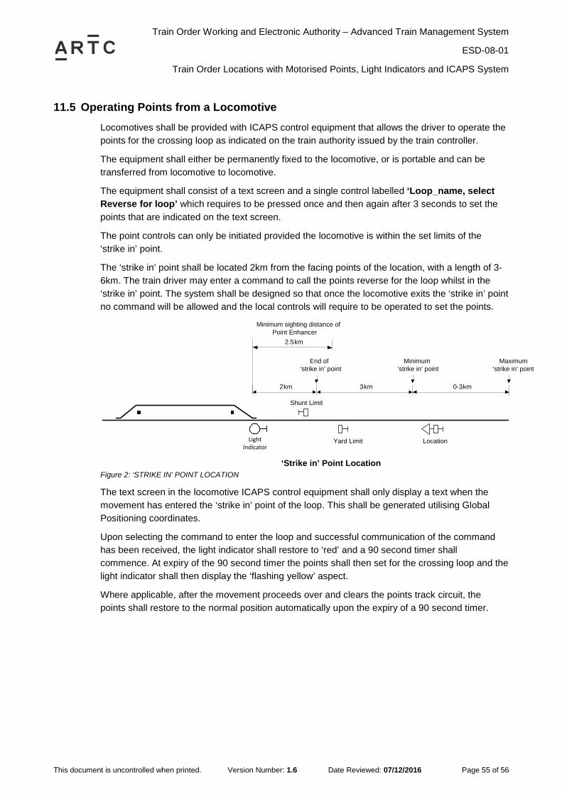
Train Order Working and Electronic Authority – Advanced Train Management System
ESD-08-01
Train Order Locations with Motorised Points, Light Indicators and ICAPS System
This document is uncontrolled when printed. Version Number: 1.6 Date Reviewed: 07/12/2016 Page 55 of 56
11.5 Operating Points from a Locomotive Locomotives shall be provided with ICAPS control equipment that allows the driver to operate the points for the crossing loop as indicated on the train authority issued by the train controller.
The equipment shall either be permanently fixed to the locomotive, or is portable and can be transferred from locomotive to locomotive.
The equipment shall consist of a text screen and a single control labelled ‘Loop_name, select Reverse for loop’ which requires to be pressed once and then again after 3 seconds to set the points that are indicated on the text screen.
The point controls can only be initiated provided the locomotive is within the set limits of the ‘strike in’ point.
The ‘strike in’ point shall be located 2km from the facing points of the location, with a length of 3-6km. The train driver may enter a command to call the points reverse for the loop whilst in the ‘strike in’ point. The system shall be designed so that once the locomotive exits the ‘strike in’ point no command will be allowed and the local controls will require to be operated to set the points.
Yard Limit Location
2km 0-3km
Minimum ‘strike in’ point
Maximum ‘strike in’ point
End of‘strike in’ point
3km
Minimum sighting distance of Point Enhancer
2.5km
‘Strike in’ Point Location
Shunt Limit
Light Indicator
Figure 2: ‘STRIKE IN’ POINT LOCATION
The text screen in the locomotive ICAPS control equipment shall only display a text when the movement has entered the ‘strike in’ point of the loop. This shall be generated utilising Global Positioning coordinates.
Upon selecting the command to enter the loop and successful communication of the command has been received, the light indicator shall restore to ‘red’ and a 90 second timer shall commence. At expiry of the 90 second timer the points shall then set for the crossing loop and the light indicator shall then display the ‘flashing yellow’ aspect.
Where applicable, after the movement proceeds over and clears the points track circuit, the points shall restore to the normal position automatically upon the expiry of a 90 second timer.
5.

Train Order Working and Electronic Authority – Advanced Train Management System
ESD-08-01
Locations not to be considered Train Order Areas
This document is uncontrolled when printed. Version Number: 1.6 Date Reviewed: 07/12/2016 Page 56 of 56
12 Locations not to be considered Train Order Areas
12.1 Introduction Certain locations, because of their track complexity, and their level crossing protection requirements combined with operational needs, cannot be adequately covered with train order infrastructure. These locations are to be normal signalled areas and removed from the train order area.
12.2 Conditions that cannot be fulfilled by Train Order Infrastructure Where the following situations occur, consideration is to be given to normal signalling in lieu of train orders:
a. Where train movements are more effectively controlled by a Signaller with signal box type facilities.
b. Where multiple indicators or signals are required in the one running direction and it is necessary to have one provide a warning that the next signal is displaying a restrictive indication (e.g. stop or turnout).
c. Where shunting movements are to occur in loops or Main lines by private operators not specifically accredited for Train Order Working, or fitted with train radio.
d. Where one or more level crossings exist where protective main line indicators or signals may require to be cleared without a clearance right through the interlocking, or for shunting purposes.
e. Some combination of the above.