© train signal, inc, 2003 - · deploying complex configurations and then modifying them...
TRANSCRIPT


© Train Signal, Inc, 2003
Computer Name: Srv-11st NIC-IP Address: 192.168.1.201/242nd NIC-IP Address: 15.15.15.15/8OS: W2K Server/SP2Services:ICSNAT
Hub Hub
Computer Name: Client-1Static IP: 192.168.1.1/24Default Gateway: 192.168.1.201/24OS: W2K Professional/SP2
Computer Name: Srv-11Static IP: 15:15:15:20/8Default Gateway: 15.15.15.15/8OS: W2K Server/SP2Services:IIS 5.0
Internet Gateway
Lab Setup
Internet
Internet Gateway Lab 1
Green Lizard Books Inc.
Private LAN
Windows 2000 Server with ICS enabled
Client Computers
T1 Connectivity

© Train Signal, Inc, 2003
Internet
Internet Gateway Lab 2
Green Lizard Books Inc.
Private LAN
Windows 2000 Server with NAT
Client Computers
T1 Connectivity
File Server Domain Controller
Internet
Internet Gateway Lab 3
Green Lizard Books Inc.
Private LAN
Windows 2000 Server with ISA Server
Client Computers
T1 Connectivity
File Server Domain Controller

Page 1 of 102 © Train Signal, Inc., 2002-2003
Configuring an Internet Gateway using ISA Server, NAT & ICS for
Green Lizard Books, Inc.
Mega Lab 7
Part 1 of 3 in the Windows 2000/2003 Routing & Remote Access Series

Page 2 of 102 © Train Signal, Inc., 2002-2003

Page 3 of 102 © Train Signal, Inc., 2002-2003
About the Authors Scott Skinger (MCSE, CNE, CCNP, A+) is the owner of Train Signal, Inc. and is an experienced Windows 2000 instructor. He has also worked in the trenches as a Network Engineer, Director of Technology and currently as an Independent Consultant through his own company, SAS Technology Advisors. As an instructor, he has taught over 50 courses, covering topics such as Windows 2000, NT 4, Novell NetWare, Cisco Routers and security. Wilson Chan (MCSA) is responsible for content development for the Routing and Remote Access Mega Lab Series. He also does network support, computer hardware repair and software support for a computer consulting company. Train Signal, Inc. 400 West Dundee Road Suite #106 Buffalo Grove, IL 60089 Phone - (847) 229-8780 Fax – (847) 229-8760 www.trainsignal.com Copyright and other Intellectual Property Information © Train Signal, Inc., 2002-2003. All rights are reserved. No part of this publication, including written work, videos and on-screen demonstrations (together called “the Information” or “THE INFORMATION”), may be reproduced or distributed in any form or by any means without the prior written permission of the copyright holder. Products and company names, including but not limited to, Microsoft, Novell and Cisco, are the trademarks, registered trademarks and service marks of their respective owners.

Page 4 of 102 © Train Signal, Inc., 2002-2003
Disclaimer and Limitation of Liability
Although the publishers and authors of the Information have made every effort to ensure that the information within it was correct at the time of publication, the publishers and the authors do not assume and hereby disclaim any liability to any party for any loss or damage caused by errors, omissions, or misleading information. TRAIN SIGNAL, INC. PROVIDES THE INFORMATION "AS-IS." NEITHER TRAIN SIGNAL, INC. NOR ANY OF ITS SUPPLIERS MAKES ANY WARRANTY OF ANY KIND, EXPRESS OR IMPLIED. TRAIN SIGNAL, INC. AND ITS SUPPLIERS SPECIFICALLY DISCLAIM THE IMPLIED WARRANTIES OF TITLE, NON-INFRINGEMENT, MERCHANTABILITY AND FITNESS FOR A PARTICULAR PURPOSE. THERE IS NO WARRANTY OR GUARANTEE THAT THE OPERATION OF THE INFORMATION WILL BE UNINTERRUPTED, ERROR-FREE, VIRUS-FREE, OR THAT THE INFORMATION WILL MEET ANY PARTICULAR CRITERIA OF PERFORMANCE OR QUALITY. YOU ASSUME THE ENTIRE RISK OF SELECTION, INSTALLATION AND USE OF THE INFORMATION. IN NO EVENT AND UNDER NO LEGAL THEORY, INCLUDING WITHOUT LIMITATION, TORT, CONTRACT, OR STRICT PRODUCTS LIABILITY, SHALL TRAIN SIGNAL, INC. OR ANY OF ITS SUPPLIERS BE LIABLE TO YOU OR ANY OTHER PERSON FOR ANY INDIRECT, SPECIAL, INCIDENTAL, OR CONSEQUENTIAL DAMAGES OF ANY KIND, INCLUDING WITHOUT LIMITATION, DAMAGES FOR LOSS OF GOODWILL, WORK STOPPAGE, COMPUTER MALFUNCTION, OR ANY OTHER KIND OF DAMAGE, EVEN IF TRAIN SIGNAL, INC. HAS BEEN ADVISED OF THE POSSIBILITY OF SUCH DAMAGES. IN NO EVENT SHALL TRAIN SIGNAL, INC. BE LIABLE FOR DAMAGES IN EXCESS OF TRAIN SIGNAL, INC.'S LIST PRICE FOR THE INFORMATION. To the extent that this Limitation is inconsistent with the locality where You use the Software, the Limitation shall be deemed to be modified consistent with such local law. Choice of Law:
You agree that any and all claims, suits or other disputes arising from your use of the Information shall be determined in accordance with the laws of the State of Illinois, in the event Train Signal, Inc. is made a party thereto. You agree to submit to the jurisdiction of the state and federal courts in Cook County, Illinois for all actions, whether in contract or in tort, arising from your use or purchase of the Information.

Page 5 of 102 © Train Signal, Inc., 2002-2003
TABLE OF CONTENTS INTRODUCTION...............................................................................................................7
LAB SETUP......................................................................................................................9
SETTING UP THE LAB...................................................................................................10 Computer 1 .................................................................................................................12 Computer 2 .................................................................................................................12 Computer 3 .................................................................................................................12
LAB 1..............................................................................................................................15
SCENARIO .....................................................................................................................16
INTERNET CONNECTION SHARING (ICS) ..................................................................18
ENABLING ICS...............................................................................................................18
SETTING UP THE VIRTUAL INTERNET ENVIRONMENT............................................22 INSTALLING IIS..........................................................................................................22 CREATING THE TEST WEB PAGE ...........................................................................23 HOSTING THE WEBSITE ON THE WEB SERVER...................................................25 TESTING ICS USING THE PING COMMAND ...........................................................29 TESTING WEB ACCESS THROUGH ICS .................................................................30
SCENARIO - PART TWO ...............................................................................................31
ICS BLOCKS ACCESS TO THE INTERNAL NETWORK FROM THE INTERNET........32
NETWORK SERVICES AND PORT NUMBERS TABLE................................................33
SETUP OF THE PUBLIC WEB SERVER ON CLIENT-1................................................34
CREATING THE WEB PAGE FOR GREEN LIZARD .....................................................35
HOSTING THE WEBSITE ..............................................................................................36
SETTING UP A HTTP FILTER TO ALLOW PUBLIC ACCESS TO THE WEBSITE.......39
LAB 2..............................................................................................................................41
SCENARIO .....................................................................................................................42
NAT (NETWORK ADDRESS TRANSLATION)...............................................................44
INSTALLING NAT...........................................................................................................44
TESTING NETWORK CONNECTIVITY THROUGH THE NAT SERVER ......................50
TESTING WEB ACCESS THROUGH THE NAT SERVER ............................................51
MANUALLY SETTING UP NAT ON YOUR RRAS SERVER .........................................52
SPECIAL PORTS – CONFIGURING REVERSE NAT TO ALLOW INTERNAL WEB ACCESS .........................................................................................................................59
CONFIGURING THE NAT PROPERTIES ......................................................................61
DNS & DHCP SERVICES WITHIN NAT.........................................................................63

Page 6 of 102 © Train Signal, Inc., 2002-2003
NAT MAPPINGS.............................................................................................................64
ENABLING DHCP ON THE NAT SERVER ....................................................................66
LAB 3..............................................................................................................................69
SCENARIO .....................................................................................................................70
WHAT IS ISA SERVER?.................................................................................................71
ISA SERVER – FEATURES & BENEFITS .....................................................................71
LAB SETUP ....................................................................................................................73
DOWNLOAD ISA SERVER ENTERPRISE EDITION.....................................................74
DOWNLOAD ISA SERVER – SERVICE PACK 1 (OPTIONAL) .....................................74
DISABLE NAT ON SRV-1...............................................................................................75
CONFIGURING THE NETWORK INTERFACES (NICS) ON SRV-1 .............................75
EXPLORING THE ISA MANAGEMENT TOOL...............................................................84
TESTS FROM SRV-1 & CLIENT-1 .................................................................................85 SITE & CONTENT RULES .........................................................................................86 PROTOCOL RULES ...................................................................................................87 IP PACKET FILTERS..................................................................................................88 CREATING A PROTOCOL RULE ..............................................................................89 TESTING CLIENT ACCESS TO THE INTERNET......................................................92 PACKET FILTER CREATION.....................................................................................93 CLIENT CONFIGURATION ........................................................................................98 SECURENAT CLIENT ................................................................................................98 FIREWALL CLIENT ....................................................................................................99 INSTALLING THE FIREWALL CLIENT ......................................................................99 WEB PROXY CLIENT...............................................................................................101

Page 7 of 102 © Train Signal, Inc., 2002-2003
Introduction Welcome to Train Signal! This series of labs on Windows 2000/2003 is designed to give you detailed, hands-on experience working with Windows 2000/2003. Train Signal’s Audio-Visual Lab courses are targeted towards the serious learner, those who want to know more than just the answers to the test questions. We have gone to great lengths to make this series appealing to both those who are seeking Microsoft certification and to those who want an excellent overall knowledge of Windows 2000/2003. Each of our courses puts you in the driver’s seat, working for different fictitious companies, deploying complex configurations and then modifying them as your company grows. They are not designed to be a “cookbook lab,” where you follow the steps of the “recipe” until you have completed the lab and have learned nothing. Instead, we recommend that you perform each step and then analyze the results of your actions in detail. To complete these labs yourself, you will need at least three computers equipped as described in the Lab Setup section. You also need to have a foundation in Windows 2000 and TCP/IP concepts. You should be comfortable with installing Windows 2000 Professional or Server and getting the basic operating system up and running. Each of the labs in this series will start from a default installation of Windows 2000 and will then run you through the basic configurations and settings that you must use for the labs to be successful. It is very important that you follow these guidelines exactly, in order to get the best results from this course. The course also includes a CD-ROM that features an audio-visual walk-through of all of the labs in the course. In the walk-through, you will be shown all of the details from start to finish on each step, for every lab in the course. During the instruction, you will also benefit from live training that discusses the current topic in great detail, making you aware of many of the associated fine points. Thank you for choosing Train Signal!

Page 8 of 102 © Train Signal, Inc., 2002-2003

Page 9 of 102 © Train Signal, Inc., 2002-2003
Lab Setup

Page 10 of 102 © Train Signal, Inc., 2002-2003
Setting up the Lab 1. Computer Equipment Needed
Item
Minimum
Recommended
Computers
(3) Pentium I 133 MHz
(3) Pentium II 300MHz or greater
Memory
128 MB
256 MB
Hard Drive
2 GB
4 GB or larger
NIC
1/machine (2 computers) 2 NICs for the Internet gateway machine (1 computer)
1/machine (2computers) 2 NICs for the Internet gateway machine (1 computer)
Hubs/Switches
2
2
Network Cable
(4) Category 5 cables
(4) Category 5 cables
I strongly urge you to acquire all of the recommended equipment in the list above. It can all be easily purchased from eBay or another source for around $400 (less if you already have some of the equipment). This same equipment is used over and over again in all of Train Signal’s labs and will also work great in all sorts of other network configurations that you may want to set up in the future. It will be an excellent investment in your education. You may also want to look into a disk-imaging product such as Norton Ghost. Disk imaging software will save you a tremendous amount of time when it comes to reinstalling Windows 2000 for future labs. Many vendors offer trial versions or personal versions of their products that are very inexpensive.

Page 11 of 102 © Train Signal, Inc., 2002-2003
2. Computer Configuration Overview
Computer Number
1
2
3
Computer Name
SRV-1
SRV-11
Client-1
IP Address
NIC #1 192.168.1.201/24 NIC #2 15.15.15.15/8
15.15.15.20/8
192.168.1.1/24
Default Gateway None 15.15.15.15 192.168.1.201
OS
W2K Server
W2K Server
W2K Pro
Additional Configurations
SP2
SP2
SP2
3. Detailed Lab Configuration ***Important Note*** This lab should NOT be performed on a live production network. You should only use computer equipment that is not part of a business network AND is not connected to a business network. Train Signal Inc. is not responsible for any damages. Refer to the full disclaimer and limitation of liability, which appears at the beginning of this document and on our website at: http://www.trainsignal.com/legalinfo.html

Page 12 of 102 © Train Signal, Inc., 2002-2003
Computer 1 Computer 1 will be named SRV-1 and the operating system on this computer will be Windows 2000 Server or Advanced Server. You should also install Service Pack 2 to avoid any unforeseen problems. If you do not have a copy of Windows 2000 Server you can obtain an evaluation copy of Windows 2000 Advanced Server within the Microsoft Press series of books, and Service Pack 2 is available for download on Microsoft’s Website. SRV-1 will have 2 network cards, each with a static IP address. One should be configured as 192.168.1.201 with a 255.255.255.0 subnet mask. You should rename this interface “private” so that it is easy to identify throughout the lab. The other network card will be configured with 15.15.15.15 as the IP address and the subnet mask will be 255.0.0.0. This interface should be renamed “public” also for easy identification. The default gateway field and the DNS Server field should be left blank. See figure 1, next page. Computer 2 Computer 2 will be named SRV-11 and Windows 2000 Server (either version once again) will be installed on this computer with Service Pack 2. SRV-11 will have a static IP address of 15.15.15.20 with a 255.0.0.0 subnet mask. The default gateway should be configured to point to SRV-1’s public IP address, 15.15.15.15. The DNS Server field should be left blank. See figure 1, next page. Computer 3 Computer 3 will be named Client-1 and will have Windows 2000 Professional installed as the operating system. Client-1 will have a static IP address of 192.168.1.1 with a 255.255.255.0 subnet mask. The default gateway should be configured to point to SRV-1’s private IP address, 192.168.1.201. The DNS server field should be left blank. See figure 1, next page. Important - You should test the network connections (using the PING command) between each of these machines to ensure that your network is set up properly. Testing before you get started will save you major time and effort later.

Page 13 of 102 © Train Signal, Inc., 2002-2003
(figure 1)
***Important Note*** This lab should NOT be performed on a live production network. You should only use computer equipment that is not part of a business network AND that is not connected to a business network. Train Signal Inc. is not responsible for any damages. Refer to the full disclaimer and limitation of liability which appears at the beginning of this document and on our web site at www.trainsignal.com

Page 14 of 102 © Train Signal, Inc., 2002-2003

Page 15 of 102 © Train Signal, Inc., 2002-2003
Lab 1
Establishing an Internet Connection for Green Lizard Books, Inc. using
Internet Connection Sharing (ICS)
You will learn how to:
• Prepare your network for ICS • Enable ICS within Windows 2000
• Setup a web server to act as a virtual Internet • Identify and work with TCP/IP Port Numbers
• Setup a HTTP filter to allow public access to a web server

Page 16 of 102 © Train Signal, Inc., 2002-2003
Scenario Green Lizard Books, Inc. is a small book distributor located in Chicago, IL. Their office currently has 1 server, which is running Windows 2000 Server, and 10 workstations, all running Windows 2000 Professional. The company recently just leased a full T1 line (1.544 Mbps) with one public IP address through a local ISP (Internet Service Provider) and only the server is connected to the Internet. Bill, the owner of Green Lizard, wants all of the other computers to have the ability to access the Internet. He hired you, as an outside consultant, to configure his computers so that they all have Internet access. During your meetings with Bill, you inform him that there are 2 services that are included with Windows 2000 Server, which will meet his goal of allowing Internet access to all of the end users. These two services are Internet Connection Sharing (ICS) and Network Address Translation (NAT). After a brief meeting with Bill, he decides to use ICS as the Internet gateway for his company, because he feels that it’s simplicity is more suitable for his environment. In this lab, you will setup, configure and test ICS. This will be done by setting up a basic web server and simulating an Internet environment. You will also learn how to setup and configure services behind the ICS Server, allowing public users access to your website, FTP server or any other service you choose to share.

Page 17 of 102 © Train Signal, Inc., 2002-2003

Page 18 of 102 © Train Signal, Inc., 2002-2003
Internet Connection Sharing (ICS)
ICS is a new feature in Windows 2000 that allows easy access to the Internet for small organizations or home offices with a small number of computers. It allows computers on the same network segment to access the Internet through a shared connection. It is available on both Windows 2000 Professional and Server. It is designed for smaller companies that want a no hassle solution, companies that do not run Windows 2000 Server or home users who want to access the Internet on multiple computers. Enabling ICS 1. SRV-1 is connected to both your private and public networks and will act as the gateway
to the Internet. Therefore, you will need to enable ICS on the public side of SRV-1, sharing the network card that is plugged into the Internet. Log on to SRV-1 and go to Start Settings Network and Dial-up Connections, right click the public connection, and click on Properties.
***NOTE*** If you did not rename your network cards in the lab setup, do so now. The network card with the 192.168.1.201 IP address should be renamed private & the network card with the 15.15.15.15 IP address should be renamed public. See the picture below for more details.

Page 19 of 102 © Train Signal, Inc., 2002-2003
2. Select the Sharing tab. To enable ICS, all that you have to do is to place a check mark in the box next to Enable Internet Connection Sharing for this connection, and click OK.
3. The message in the picture below should appear. In the lab setup, your private network interface was configured with the static IP address of 192.168.1.201. ICS will now automatically change your private IP address to 192.168.0.1 if you select Yes. Also, the DHCP allocator service will be enabled and begin to lease out IP address, subnet mask, and default gateway information to the internal clients on the 192.168.0.0/24 subnet. The DHCP allocator service allows ICS to lease IP addresses from its default address pool, between 192.168.0.2 and 192.168.0.254. Click Yes to enable ICS.
Page 20 of 102 © Train Signal, Inc., 2002-2003
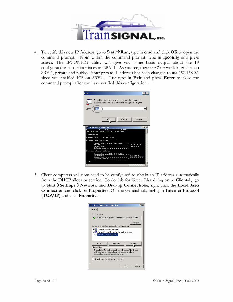
4. To verify this new IP Address, go to Start Run, type in cmd and click OK to open the command prompt. From within the command prompt, type in ipconfig and press Enter. The IPCONFIG utility will give you some basic output about the IP configurations of the interfaces on SRV-1. As you see, there are 2 network interfaces on SRV-1, private and public. Your private IP address has been changed to use 192.168.0.1 since you enabled ICS on SRV-1. Just type in Exit and press Enter to close the command prompt after you have verified this configuration.
5. Client computers will now need to be configured to obtain an IP address automatically from the DHCP allocator service. To do this for Green Lizard, log on to Client-1, go to Start Settings Network and Dial-up Connections, right click the Local Area Connection and click on Properties. On the General tab, highlight Internet Protocol (TCP/IP) and click Properties.

Page 21 of 102 © Train Signal, Inc., 2002-2003
6. On the General tab select Obtain an IP address automatically and click OK. Client-1 will now start broadcasting for an IP address on your network. Since the DHCP allocator service was automatically enabled, Client-1 should be able to obtain an IP address from SRV-1.
7. To check Client-1’s IP address go to Start Run from the desktop, type in cmd and click OK to open the command prompt. From within the command prompt type in ipconfig and press Enter.

Page 22 of 102 © Train Signal, Inc., 2002-2003
8. Client-1’s IP address should be an IP address from the network ID of 192.168.0.0/24. This is a randomly selected IP address from the DHCP allocator service address pool. Therefore, your Client-1 might be assigned a different IP address than the one (192.168.0.113) shown in the picture below. The default gateway should be set at 192.168.0.1 which is SRV-1, your Internet gateway. After you have verified this configuration, type Exit and press Enter to close the command prompt.
Setting up the virtual Internet environment Installing IIS 1. To set up the virtual Internet environment you will have to install Internet Information
Services (IIS) on SRV-11 and host a web site. IIS should already be installed by default along with your Windows 2000 server installation. If, for some reason, it is not installed, log on to SRV-11 and go to Start Settings Control Panel. Double click on the Add/Remove Programs icon and click on Add/Remove Windows Components on the left column. This will bring up the Windows Components Wizard. Place a check mark in the box next to Internet Information Services (IIS) and click Next to begin the installation. Make sure you have your Windows 2000 server disk handy because you will be asked for it during the installation. The installation should take about 5-10 minutes. You will eventually get a screen letting you know that the installation is done. Click on Finish to complete the installation.

Page 23 of 102 © Train Signal, Inc., 2002-2003
2. To confirm that Internet Information Services (IIS) is successfully installed on SRV-11, go to Start Programs Administrative tools and open Internet Services Manager. If your server shows up within the Internet Services Manager console you should be all set.
Creating the Test Web Page 1. Open Windows Explorer on the C: drive, and create a new folder named Web. This
can be done by right clicking on an empty space within the C: drive and selecting New Folder from the shortcut menu. You should now have a folder in C: called Web. Close Windows Explorer when you are finished.
2. Next, use Notepad to create a simple HTML file that will be used for our test website.
Go to Start Programs Accessories Notepad.

Page 24 of 102 © Train Signal, Inc., 2002-2003
3. In Notepad, type in Internet and then select File Save As from the menu.
4. On the Save As screen, open the Save in drop down menu and select the Web folder that you created earlier as the location to save this file. Once you have selected the folder, enter the filename main.html. Then click on the Save button and close Notepad.
5. Now open the Web folder using Windows Explorer to make sure that the file was
saved as an HTML file. Close Windows Explorer after confirming this.

Page 25 of 102 © Train Signal, Inc., 2002-2003
Hosting the Website on the Web server
1. Open Internet Service Manager and right click on SRV-11. Select New Web Site from the shortcut menu to start the new web site wizard to create a new website.
2. Within the wizard, click Next on the welcome screen. On the next screen type in:
Internet as the description for the web site and click Next to continue.

Page 26 of 102 © Train Signal, Inc., 2002-2003
3. The next screen will ask you to specify the IP address to use for the web site. Select 15.15.15.20 from the drop down menu, as it’s the only one available. Leave the default port number at 80, and the host header field blank. Click Next.
4. Specify the path to the home directory for the web content as the Web folder that you created earlier. Leave the Allow anonymous access to this Web site box checked and click Next.
5. This web site will be used as our virtual Internet environment. Just leave the Read permission and Run scripts permission checked and click Next.

Page 27 of 102 © Train Signal, Inc., 2002-2003
6. On the final screen of the wizard, click Finish and you should now see the web site for Internet appear in the left pane of Internet Services Manager.
7. Next, you should stop the Default Web Site. To stop the site, right click on the Default
Web Site and select Stop. This step is very important because the default web site is configured to listen for web requests on the same port 80 as the site that you just created. By default, only one web site can be listening for web requests on a single port at a time.

Page 28 of 102 © Train Signal, Inc., 2002-2003
8. Next, open the Properties page for the Internet web site. Right click on Internet, select Properties from the shortcut menu, and then select the Documents tab. Click on the Add button, enter main.html into the dialog box that appears and click OK. This is the name of the web page file that you created earlier. By specifying this page, you are telling the web server what page to open first - your home page. You should remove default.htm and default. asp, the other file names in this box, because they do not pertain to your site. Click OK to close the properties for the “Internet” web site. If the “Internet” web site shows as being stopped in the left pane, you will have to start the site by right clicking on Internet and selecting Start.
9. To test this web site locally, open Internet Explorer, enter 15.15.15.20 and hit Enter. You should be able to view your test web site.

Page 29 of 102 © Train Signal, Inc., 2002-2003
Testing ICS using the PING command In order to see if you have access to your virtual Internet environment through ICS, you will test it through Client-1. 1. Log on to Client-1, go to Start Run, type in cmd, and click OK to open the
command prompt. On the command prompt, type in ping 15.15.15.20 and press Enter.
2. The Ping utility is used to test the connectivity between any two machines on the
network. When you ping SRV-11 from Client-1, you should get a reply from SRV-11, indicating that the physical components (NICs, cabling, etc.) and TCP/IP are both working properly.

Page 30 of 102 © Train Signal, Inc., 2002-2003
Testing web access through ICS 1. Again on Client-1, open Internet Explorer. In the Internet Explorer address box field,
enter http://15.15.15.20 and click Go. Be patient, as it can sometimes take 30 seconds or so to first load this web page. Eventually, you should see the web site that you created earlier.

Page 31 of 102 © Train Signal, Inc., 2002-2003
Scenario - Part Two Bill (the owner of Green Lizard) calls you in today and introduces you to Joe, his new web site developer. Joe has been working on the Green Lizard Books, Inc. web site and he is now ready to host the new site on a public web server. This site should be available to all of Green Lizard’s employees AND public users on the Internet. Bill would like you to host the new site utilizing the computer equipment that Green Lizard already owns. Together, you decide to host the web site on one of the Windows 2000 Professional machines on the internal network. This machine is an extra right now and is very lightly used. You explain to Bill that, because this web site is being hosted on the internal network, a filter will have to be set up on the ICS server. This filter will redirect all HTTP (port 80) traffic received by the ICS server to the Professional machine that is hosting Green Lizard’s website. In this part of the lab, you will first examine how packet filtering works in ICS to block unwanted traffic from the public side of the ICS server. You will then set up Green Lizard’s website and host the site on your Windows 2000 professional machine, which resides on the internal network. You will then have to create a filter on your ICS Server, allowing only traffic destined to Port 80 (HTTP) into your network. This traffic will be directed to Client-1, your Windows 2000 Professional machine. Keep in mind that Internet Information Services (IIS 5) can be installed on a Windows 2000 Professional machine but it is not normally done in a production environment due to the limitations of IIS 5 on Windows 2000 Professional.

Page 32 of 102 © Train Signal, Inc., 2002-2003
ICS blocks access to the Internal Network from the Internet Since SRV-11 is acting as your virtual Internet environment, you will test communications from it to see if you can gain access to your internal network. 1. Log on to SRV-11, go to Start Run, type in cmd and click OK to open the command
prompt. From the command prompt type in ping 192.168.0.1, which is the private side of SRV-1, and press Enter.
Once again, the ping utility is used to test the connectivity between any 2 machines on the network. When you ping the private side of SRV-1 (192.168.0.1) from SRV-11, you should not get any reply from SRV-1. You get this result because ICS acts as a basic firewall, filtering out traffic from the Internet that is not specifically allowed into the network. Keep in mind, however, ICS is NOT very secure and networks with dedicated connections (i.e. DSL, T1, etc.) should be running a more sophisticated firewall product.
Page 33 of 102 © Train Signal, Inc., 2002-2003
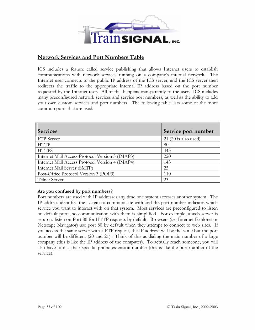
Network Services and Port Numbers Table ICS includes a feature called service publishing that allows Internet users to establish communications with network services running on a company’s internal network. The Internet user connects to the public IP address of the ICS server, and the ICS server then redirects the traffic to the appropriate internal IP address based on the port number requested by the Internet user. All of this happens transparently to the user. ICS includes many preconfigured network services and service port numbers, as well as the ability to add your own custom services and port numbers. The following table lists some of the more common ports that are used.
Services Service port number FTP Server 21 (20 is also used) HTTP 80 HTTPS 443 Internet Mail Access Protocol Version 3 (IMAP3) 220 Internet Mail Access Protocol Version 4 (IMAP4) 143 Internet Mail Server (SMTP) 25 Post-Office Protocol Version 3 (POP3) 110 Telnet Server 23 Are you confused by port numbers? Port numbers are used with IP addresses any time one system accesses another system. The IP address identifies the system to communicate with and the port number indicates which service you want to interact with on that system. Most services are preconfigured to listen on default ports, so communication with them is simplified. For example, a web server is setup to listen on Port 80 for HTTP requests by default. Browsers (i.e. Internet Explorer or Netscape Navigator) use port 80 by default when they attempt to connect to web sites. If you access the same server with a FTP request, the IP address will be the same but the port number will be different (20 and 21). Think of this as dialing the main number of a large company (this is like the IP address of the computer). To actually reach someone, you will also have to dial their specific phone extension number (this is like the port number of the service).
Page 34 of 102 © Train Signal, Inc., 2002-2003
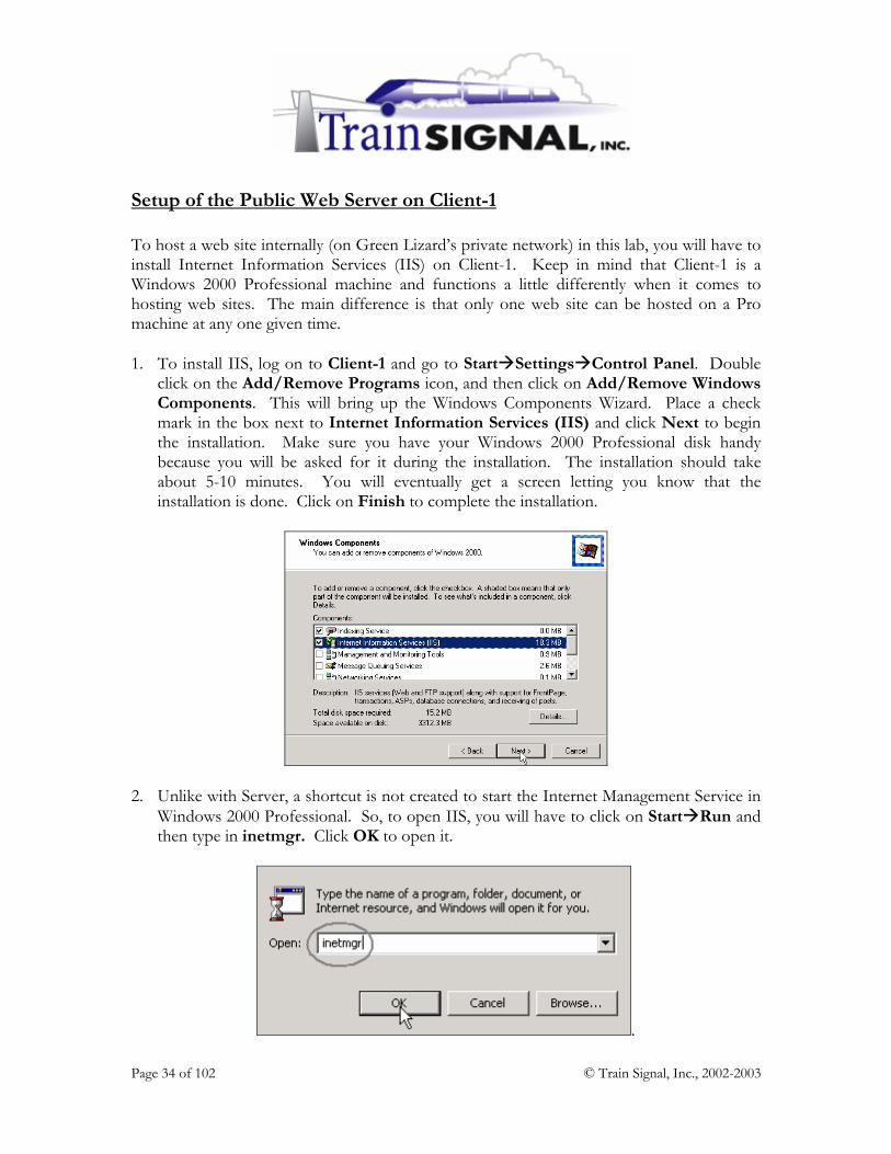
Setup of the Public Web Server on Client-1 To host a web site internally (on Green Lizard’s private network) in this lab, you will have to install Internet Information Services (IIS) on Client-1. Keep in mind that Client-1 is a Windows 2000 Professional machine and functions a little differently when it comes to hosting web sites. The main difference is that only one web site can be hosted on a Pro machine at any one given time. 1. To install IIS, log on to Client-1 and go to Start Settings Control Panel. Double
click on the Add/Remove Programs icon, and then click on Add/Remove Windows Components. This will bring up the Windows Components Wizard. Place a check mark in the box next to Internet Information Services (IIS) and click Next to begin the installation. Make sure you have your Windows 2000 Professional disk handy because you will be asked for it during the installation. The installation should take about 5-10 minutes. You will eventually get a screen letting you know that the installation is done. Click on Finish to complete the installation.
2. Unlike with Server, a shortcut is not created to start the Internet Management Service in
Windows 2000 Professional. So, to open IIS, you will have to click on Start Run and then type in inetmgr. Click OK to open it.
.

Page 35 of 102 © Train Signal, Inc., 2002-2003
Creating the web page for Green Lizard 1. Open Windows Explorer and within the C: drive create a new folder named In-house
Web Site. This can be done by right clicking on an empty space within the C: drive and selecting New Folder from the shortcut menu. Close Windows Explorer when you are finished.
2. Next, use Notepad to create a simple HTML file that will be used for Green Lizard’s
web site. Go to Start Programs Accessories Notepad.
3. In Notepad, type in WWW.GREENLIZARDBOOKS.COM and then select
File Save As from the menu.

Page 36 of 102 © Train Signal, Inc., 2002-2003
4. On the Save As screen, open the Save in drop down menu and select the In-house Web Site folder that you created earlier as the location to save this file. Once you have selected the folder, enter the filename main.html. Next, click on the Save button and close Notepad.
5. Next, open the In-house Web Site folder using Windows Explorer to make sure that
the file was saved as a HTML file (see the picture below). Close Windows Explorer.
Hosting the Website 1. From the desktop, click on Start Run then type in inetmgr and click OK to open IIS.
Right click on Default Web Site and select Properties.

Page 37 of 102 © Train Signal, Inc., 2002-2003
2. This should bring you to the screen shown below. From here you will have to specify the IP address to use for Green Lizard’s web site.
Select Client-1’s IP address from the drop down arrow in the IP address field, as it can be different to the one I have here. This is because Client-1’s IP address was randomly selected from SRV-1’s DHCP allocator service address pool. Leave the other settings as they are and click Apply.
***NOTE*** In a production environment a static IP address should be used on the web server so that the ICS Services configuration matches the IP address of the web server at all times. 3. Select the Home Directory tab, specify the Local Path as the In-house Web Site
folder and click Apply.
Page 38 of 102 © Train Signal, Inc., 2002-2003
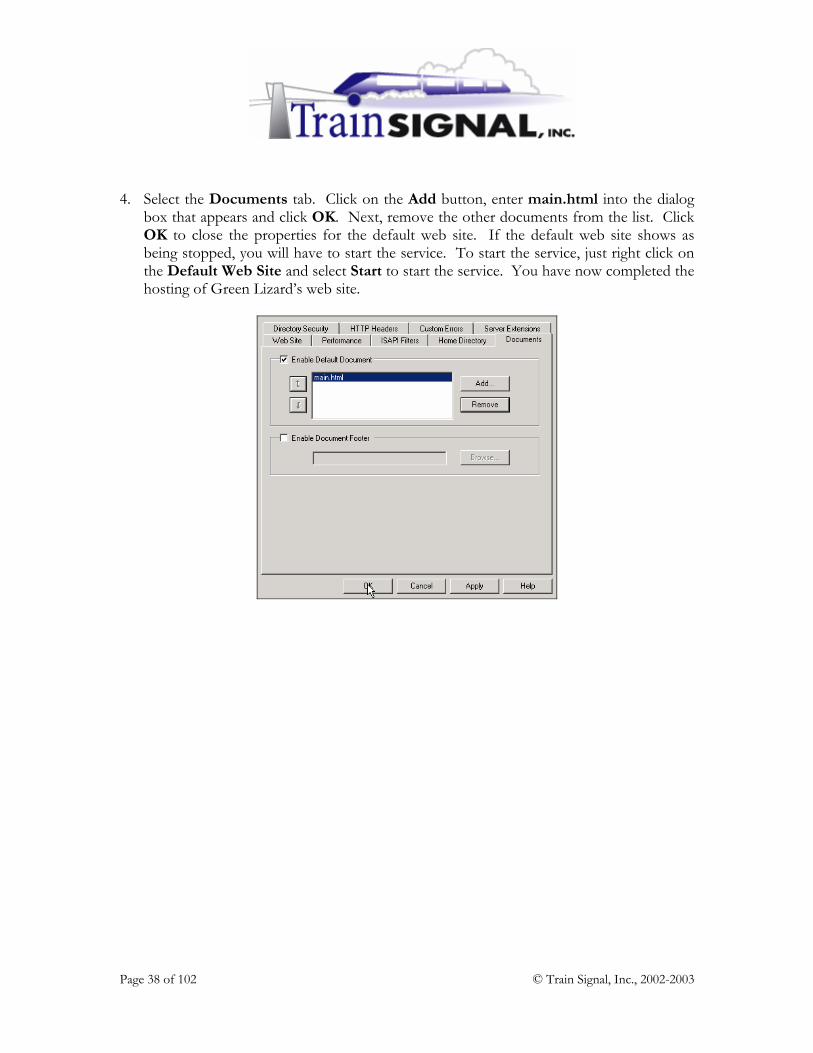
4. Select the Documents tab. Click on the Add button, enter main.html into the dialog
box that appears and click OK. Next, remove the other documents from the list. Click OK to close the properties for the default web site. If the default web site shows as being stopped, you will have to start the service. To start the service, just right click on the Default Web Site and select Start to start the service. You have now completed the hosting of Green Lizard’s web site.

Page 39 of 102 © Train Signal, Inc., 2002-2003
Setting up a HTTP filter to allow public access to the website Before external users can gain access to Green Lizard’s website, you will have to setup a HTTP filter on ICS. 1. Log on to SRV-1 and go to Start Settings Network and Dial-up Connections,
right click the public connection, and click on Properties. Select the Sharing tab, and click on the Settings button.
2. This will bring you to the Internet Connection Sharing Settings screen. Select the Services tab, and click Add to add a new network service. If you wanted to use a pre-defined service (i.e. FTP) you would only need to check the appropriate box.
Page 40 of 102 © Train Signal, Inc., 2002-2003
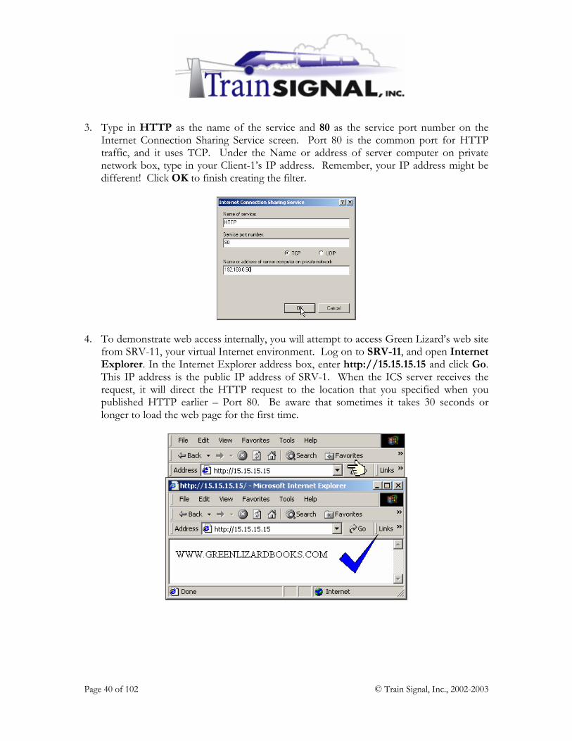
3. Type in HTTP as the name of the service and 80 as the service port number on the Internet Connection Sharing Service screen. Port 80 is the common port for HTTP traffic, and it uses TCP. Under the Name or address of server computer on private network box, type in your Client-1’s IP address. Remember, your IP address might be different! Click OK to finish creating the filter.
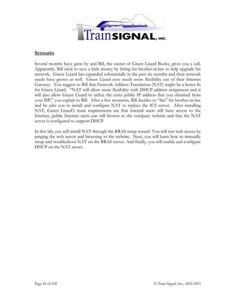
4. To demonstrate web access internally, you will attempt to access Green Lizard’s web site from SRV-11, your virtual Internet environment. Log on to SRV-11, and open Internet Explorer. In the Internet Explorer address box, enter http://15.15.15.15 and click Go. This IP address is the public IP address of SRV-1. When the ICS server receives the request, it will direct the HTTP request to the location that you specified when you published HTTP earlier – Port 80. Be aware that sometimes it takes 30 seconds or longer to load the web page for the first time.

Page 41 of 102 © Train Signal, Inc., 2002-2003
Lab 2
Establishing an Internet Connection for
Green Lizard Books, Inc. using Network Address Translation (NAT)
You will learn how to:
• Install NAT through the RRAS wizard • Manually setup NAT within RRAS
• Configure reverse NAT to allow internal web access • Examine & Configure the properties of NAT • Enable the DHCP Service on a NAT server
Page 42 of 102 © Train Signal, Inc., 2002-2003
Scenario Several months have gone by and Bill, the owner of Green Lizard Books, gives you a call. Apparently, Bill tried to save a little money by hiring his brother-in-law to help upgrade his network. Green Lizard has expanded substantially in the past six months and their network needs have grown as well. Green Lizard now needs more flexibility out of their Internet Gateway. You suggest to Bill that Network Address Translation (NAT) might be a better fit for Green Lizard. “NAT will allow more flexibility with DHCP address assignment and it will also allow Green Lizard to utilize the extra public IP address that you obtained from your ISP,” you explain to Bill. After a few moments, Bill decides to “fire” his brother-in-law and he asks you to install and configure NAT to replace the ICS server. After installing NAT, Green Lizard’s main requirements are that internal users still have access to the Internet, public Internet users can still browse to the company website and that the NAT server is configured to support DHCP. In this lab, you will install NAT through the RRAS setup wizard. You will test web access by pinging the web server and browsing to the website. Next, you will learn how to manually setup and troubleshoot NAT on the RRAS server. And finally, you will enable and configure DHCP on the NAT server.

Page 43 of 102 © Train Signal, Inc., 2002-2003

Page 44 of 102 © Train Signal, Inc., 2002-2003
NAT (Network Address Translation) NAT is a new feature in Windows 2000. It is an internet standard that is offered in Windows 2000 Server to provide small to medium sized networks access to the Internet, while maintaining their private class IP structure on the internal network. It is scalable and offers many configuration options that Internet Connection Sharing (ICS) does not, such as multiple public IP addresses and custom configurations within DHCP. You can have as many private IP addresses as you want that will all “map” through the same public IP address, providing access to the Internet. As mentioned above, NAT is an Internet standard, not just a Windows 2000 feature, and is therefore found in many different firewall and Internet connection products. Within Windows 2000, NAT is only offered in Windows 2000 Server, NOT Professional. NAT is very similar to ICS, but is a step-up for companies that need a little more flexibility in their Internet solution. Installing NAT 1. Before installing NAT, you first must disable ICS on SRV-1 from our previous lab.
Note, ICS and NAT cannot be installed on the same computer. To do this, log on to SRV-1, go to Start Settings Network and Dial-up Connections, right-click the public connection, and click on Properties.

Page 45 of 102 © Train Signal, Inc., 2002-2003
2. Select the Sharing tab and un-check the box next to Enable Internet Connection Sharing for this connection. Click OK and ICS will now be disabled. Since ICS is disabled, the DHCP allocator service will not be able to lease out IP addresses, subnet masks or default gateway information. You must, therefore, make sure that all of the IP addresses on each computer are properly assigned as was originally specified. Refer to the Computer Configuration Overview if you have any questions on this.
After the previous steps are completed and your network is setup as specified, you are ready to install NAT. First, you need to configure and enable Routing and Remote Access. RRAS is located under Administrative Tools. When you first open it up, notice that RRAS is installed as part of the default Windows 2000 server installation, but it is disabled. In this lab, SRV-1 is connected to both your private and public networks and will act as the gateway to the Internet, just like in the last lab. SRV-1 is where you will install NAT.

Page 46 of 102 © Train Signal, Inc., 2002-2003
3. On SRV-1 go to Start Programs Administrative Tools and click on Routing and Remote Access. Right click SRV-1 and click Configure and Enable Routing And Remote Access. Once again, notice that although RRAS is installed with Windows 2000 by default, it is not enabled until you make it so.
4. This will bring up the Routing and Remote Access Server Setup Wizard. Click Next to
continue.

Page 47 of 102 © Train Signal, Inc., 2002-2003
5. On the Common Configurations page, there are 5 common configurations for you to choose from, including NAT. You can turn your server into a Remote access server, a VPN server or a Network router, to name but a few. We will cover these areas in great detail in upcoming labs. For now, select the Internet Connection Server and click Next to continue with the installation.
6. This will bring you to the Internet Connection Server Setup screen. As you can see,
there are 2 choices for you to choose from during setup, ICS or NAT. Notice that you have the choice to setup ICS through RRAS, but selecting this option will only direct you to use similar steps that you walked through in Lab 1. In this lab, you will setup NAT. Therefore, select Set up a router with the Network Address Translation (NAT) routing protocol and click Next.

Page 48 of 102 © Train Signal, Inc., 2002-2003
7. The next screen of the wizard will ask you to either use the selected Internet connection or create a new demand-dial Internet connection to access the Internet. Demand dial connections are typically only configured if you are using a modem or an ISDN line to access the Internet. In this lab, and in most real world cases, you will be connecting your NAT server’s 2nd network card (public network card) to the device supplying you with the Internet connection (i.e. DSL Router, Cable Modem or T-1 Router).
Select Use the selected Internet connection. Down below, there are 2 network interfaces for you to choose from - MAKE SURE that you select the interface with the public IP address. In the lab, this interface should be marked public, with the IP address of 15.15.15.15. Remember, in a real world scenario, your Internet Service Provider will provide you with this address and the interface would be connected to the public side of your network. Therefore, highlight public and click Next.

Page 49 of 102 © Train Signal, Inc., 2002-2003
8. On this screen, you will be asked to enable basic name and address services. You can enable DNS and DHCP on NAT if you don’t have these services on your network. For DHCP, NAT will provide an address range generated from the IP address of your internal adapter. But, you can always change the range by defining a new static address on your internal adapter. For now, as you are not going enable these services, just select I will setup name and address services later and click Next.
9. On the last screen of the wizard, verify that the network interface serving the Internet is public and that the NAT routing protocol was installed on SRV-1. Click Finish and you will complete the installation.

Page 50 of 102 © Train Signal, Inc., 2002-2003
Testing network connectivity through the NAT Server In order to see if you have access to your virtual Internet environment through NAT, you will have to test it from Client-1. Make sure that you set Client-1’s IP address configuration back to the way it was in the Lab Setup or you will not be able to access the web server. . 1. Log on to Client-1, go to Start Run, type in cmd and click OK to open the command
prompt. Within the command prompt type in ping 15.15.15.20 and press Enter.
2. When you ping SRV-11 from Client-1, you should get a reply from SRV-11, which
means that SRV-1 is working properly as our Internet gateway.

Page 51 of 102 © Train Signal, Inc., 2002-2003
Testing web access through the NAT Server 1. Again on Client-1, open Internet Explorer. In the Internet Explorer address box, enter
http://15.15.15.20 and click Go. Be aware that sometimes it does take 30 seconds to load the web page. This should take you to the Internet web site that you created previously in Lab 1.
Page 52 of 102 © Train Signal, Inc., 2002-2003
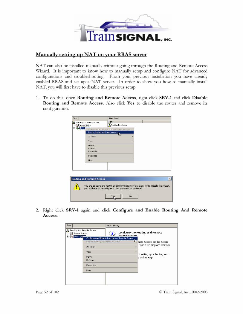
Manually setting up NAT on your RRAS server NAT can also be installed manually without going through the Routing and Remote Access Wizard. It is important to know how to manually setup and configure NAT for advanced configurations and troubleshooting. From your previous installation you have already enabled RRAS and set up a NAT server. In order to show you how to manually install NAT, you will first have to disable this previous setup. 1. To do this, open Routing and Remote Access, right click SRV-1 and click Disable
Routing and Remote Access. Also click Yes to disable the router and remove its configuration.
2. Right click SRV-1 again and click Configure and Enable Routing And Remote Access.

Page 53 of 102 © Train Signal, Inc., 2002-2003
3. This will bring up the Routing and Remote Access Server Setup Wizard, just click Next to continue.
4. Again, on the Common Configurations page, there are 5 common configurations for you to choose from. This time, you will select Manually configured server to start the server with its default settings. Just click Next to continue with the installation.

Page 54 of 102 © Train Signal, Inc., 2002-2003
5. Click Finish to complete the installation. Also click Yes to start the RRAS service. These steps are relatively short when compared to setting up NAT through the wizard. This is because you will install and configure the NAT components manually on the RRAS server.
6. The first step that is necessary in order to install NAT manually is to install the NAT protocol or service. To accomplish this, you will need to double click on SRV-1, and then double click to expand IP Routing. Right click General and then click on New Routing Protocol.

Page 55 of 102 © Train Signal, Inc., 2002-2003
7. In the New Routing Protocol dialog box, highlight Network Address Translation (NAT), and click OK. You will notice that the Network Address Translation (NAT) routing protocol is immediately installed under IP routing.
8. In order to enable NAT on SRV-1, you will have to add a public and a private interface. This step “educates” the NAT server as to which network card is plugged into your company’s private network, and which network card is plugged into the public side. On SRV-1 you have two interfaces, named private and public. To add these two interfaces within the NAT configuration, right click Network Address Translation (NAT), and then click New Interface.

Page 56 of 102 © Train Signal, Inc., 2002-2003
9. In the New Interface for Network Address Translation (NAT) dialog box, click on private and then click OK.
10. Since private is the name of the interface connected to your internal network, select Private interface connected to private network in this next step and click OK. This allows the NAT server to determine which network card is plugged into the private network.

Page 57 of 102 © Train Signal, Inc., 2002-2003
11. Next, you will specify the public interface. Once again, right click Network Address Translation (NAT), and then click New Interface.
12. In the New Interface for Network Address Translation (NAT) dialog box, click on the remaining interface, public, and then click OK.

Page 58 of 102 © Train Signal, Inc., 2002-2003
13. Public is the interface connected to your virtual Internet environment. You will need to select Public interface connected to the Internet and also the Translate TCP/UDP headers check box. By selecting the Translate TCP/UDP headers check box, NAT will perform TCP port and UDP port translation along with IP address translation. Since you only have one public address in this lab, you must select this check box. Otherwise, network traffic from hosts on the private network cannot be properly translated to Internet traffic. Click Apply to configure public as your public interface.
14. After specifying your public interface, there are several tabs and many options that you can configure. Still within the public interface, click on the Address Pool tab - this is where you can optionally configure additional public IP addresses that your ISP assigned to your network. Click Add to specify your start and end range. You can also reserve public IP addresses for specific internal machines. Reservations enable your internal clients to always use the same public IP address when they connect to the Internet.
Page 59 of 102 © Train Signal, Inc., 2002-2003
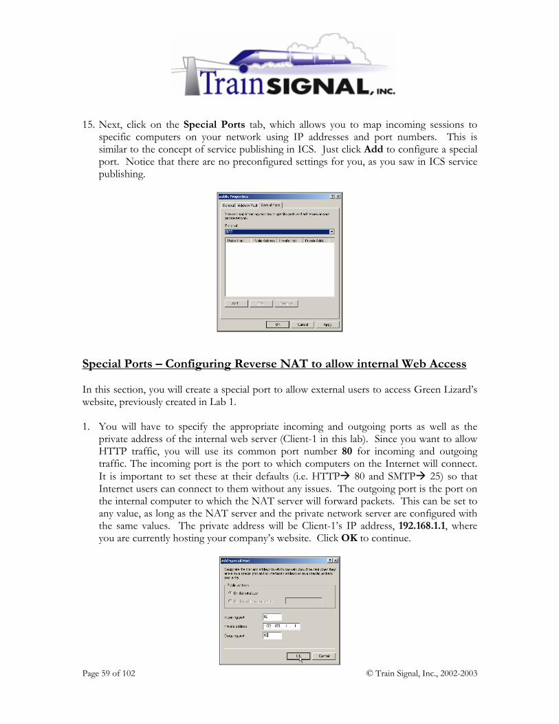
15. Next, click on the Special Ports tab, which allows you to map incoming sessions to specific computers on your network using IP addresses and port numbers. This is similar to the concept of service publishing in ICS. Just click Add to configure a special port. Notice that there are no preconfigured settings for you, as you saw in ICS service publishing.
Special Ports – Configuring Reverse NAT to allow internal Web Access In this section, you will create a special port to allow external users to access Green Lizard’s website, previously created in Lab 1. 1. You will have to specify the appropriate incoming and outgoing ports as well as the
private address of the internal web server (Client-1 in this lab). Since you want to allow HTTP traffic, you will use its common port number 80 for incoming and outgoing traffic. The incoming port is the port to which computers on the Internet will connect. It is important to set these at their defaults (i.e. HTTP 80 and SMTP 25) so that Internet users can connect to them without any issues. The outgoing port is the port on the internal computer to which the NAT server will forward packets. This can be set to any value, as long as the NAT server and the private network server are configured with the same values. The private address will be Client-1’s IP address, 192.168.1.1, where you are currently hosting your company’s website. Click OK to continue.

Page 60 of 102 © Train Signal, Inc., 2002-2003
2. Verify your configuration, and click OK to finish.
3. To once again demonstrate web access internally, you will have to access your company’s
web site through SRV-11, your virtual Internet environment. Log on to SRV-11, and open up Internet Explorer. Within the Internet Explorer address box, enter http://15.15.15.15 and click Go. This will direct you to the web site you created in Lab 1. Be aware that sometimes it does take 30 seconds or so to load the web page and you often have to reboot your system in order for it to work.

Page 61 of 102 © Train Signal, Inc., 2002-2003
Configuring the NAT properties 1. There are many features that you can configure within NAT. To configure NAT, just
right click on Network Address Translation (NAT), and select Properties.
2. This will bring you to the Network Address Translation (NAT) Properties dialog box. There are 4 tabs (General, Translation, Address Assignment and Name Resolution) for you to select and many options to configure. The General tab lists the different logging options that you can choose from. No matter which option you select, all of the events are logged in the system log of the event viewer. You also have an option to disable event logging. The default setting is to Log errors only, which is great unless you want to see more detailed information about NAT.

Page 62 of 102 © Train Signal, Inc., 2002-2003
3. The next tab is the Translation tab. The settings that you will find here allow you to control how long the NAT mappings are maintained within the NAT table. This is the amount of time that a dynamic mapping for a TCP or a UDP session will remain in the NAT table. The default settings for TCP and UDP are 1440 minutes and 1 minute respectively. This tab also includes an applications button. This button is very similar to the button in Internet Connection Sharing that allows you to configure special applications that are more complicated, such as chat, to be available to your internal users.
4. Moving forward, the third tab is the Address Assignment tab. It allows you to configure SRV-1 to act as a DHCP server and lease out IP addresses. The network ID is set to 192.168.0.0/24 as the default. But, unlike ICS, which can only strictly lease out addresses on a 192.168.0.0/24 subnet, NAT gives you the flexibility to change to any network ID. In addition, you can also add an exclusion range by clicking the Exclude button. You will examine this task in more detail in the last section of this lab.

Page 63 of 102 © Train Signal, Inc., 2002-2003
5. The last tab is the Name Resolution tab. It allows you to configure SRV-1 to act as a DNS proxy server to resolve IP addresses for clients. When a NAT server receives a DNS query, it acts as a DNS proxy, passing the DNS request along to the DNS Server configured on its public interface, typically an ISP’s DNS server. In other words, make sure that you configure the preferred DNS server setting on the public interface of the NAT server, with a DNS Server IP address that can resolve Internet names. You can also specify a demand-dial interface, such as a modem, if necessary. Click OK to close the Network Address Translation (NAT) Properties.
DNS & DHCP Services within NAT 1. DNS & DHCP can be monitored on the NAT server by right clicking on Network
Address Translation (NAT) and selecting Show DHCP Allocator Information or Show DNS Proxy Information, which will bring you statistics on these particular services.

Page 64 of 102 © Train Signal, Inc., 2002-2003
2. The DHCP Allocator component provides IP address configuration information to DHCP clients on the network. The DHCP Allocator Information can be helpful when you are troubleshooting DHCP or trying to determine whether your DHCP server is functioning correctly.
3. The DNS proxy component acts as a DNS server to all of the NAT client computers on the network. DNS queries and responses, as well as other DNS information is shown within this table.
NAT Mappings Some other very important statistics that you can view are statistics for NAT interfaces on your computer. The details pane on the right of your NAT server has columns for Total mappings, Inbound packets translated, Inbound packets rejected, Outbound packets translated and Outbound packets rejected. These mappings are dynamically updated. 1. These statistics show outbound and inbound internet traffic.

Page 65 of 102 © Train Signal, Inc., 2002-2003
2. In addition, you can see the current mappings table for each interface. Just right click on the interface, and click Show Mappings.
3. This will bring you to the Network Address Translation Session Mapping Table. In this
table, you will see exactly what protocols, ports, and addresses are mapped in memory for that particular interface.
Notice that the private address listed above is an address from your private network (192.168.1.0). The private port is any random port above 1,000 and the combination of the two represent Client-1’s session with the NAT server. This IP/Port information is then mapped to the public interface of the NAT Server, 15.15.15.15. The public port, which belongs to the NAT server, is always the same port number that the client supplied. The remote address and port number belong to the web server that the client is connecting to.

Page 66 of 102 © Train Signal, Inc., 2002-2003
Enabling DHCP on the NAT server NAT also includes a feature that allows you to enable a basic DHCP server with more flexibility than ICS offers. This implementation of DHCP does not restrict you to using the 192.168.0.0/24 network ID, as ICS does. You have the ability to use any Network ID you desire for your network. 1. To enable DHCP within NAT, right click on Network Address Translation (NAT)
again and select Properties. Select the Address Assignment tab, and place a check mark in the box next to Automatically assign IP addresses by using DHCP. Since Green Lizard is using the 192.168.1.0/24 network ID, change the IP address field to 192.168.1.0 and set the mask to 255.255.255.0.
2. You should also be sure to exclude the NAT server’s IP address, so it is not assigned to a
DHCP client that is requesting an IP address. To exclude this address, click on Exclude and click Add to enter the internal IP address of the NAT server, 192.168.1.201. For test purposes, you should also exclude Client-1’s IP address, 192.168.1.1. Now, when Client-1 obtains an IP address automatically from SRV-1, you will see a different IP address being assigned than 192.168.1.1.

Page 67 of 102 © Train Signal, Inc., 2002-2003
3. To test the DHCP server, log on to Client-1, go to Start Settings Network and Dial-up Connections, right click the Local Area Connection, and click on Properties. On the General tab, highlight Internet Protocol (TCP/IP), and click on Properties.
4. On the General tab select Obtain an IP address automatically, and click OK.
Page 68 of 102 © Train Signal, Inc., 2002-2003
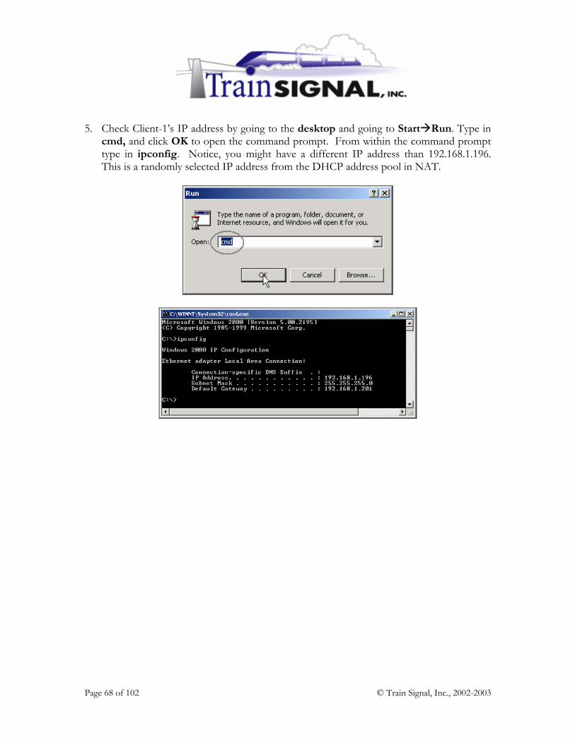
5. Check Client-1’s IP address by going to the desktop and going to Start Run. Type in cmd, and click OK to open the command prompt. From within the command prompt type in ipconfig. Notice, you might have a different IP address than 192.168.1.196. This is a randomly selected IP address from the DHCP address pool in NAT.

Page 69 of 102 © Train Signal, Inc., 2002-2003
Lab 3
Establishing an Internet Connection for
Green Lizard Books, Inc. using Internet Security & Acceleration (ISA) Server
You will learn how to:
• Determine whether ISA Server is right for your company • Prepare a server for ISA Server installation
• Install ISA Server • Create Access Policy to control users on a network
• Configure client computers as ISA Clients

Page 70 of 102 © Train Signal, Inc., 2002-2003
Scenario You just got off of the phone with Bill, the owner of Green Lizard Books. Apparently, nobody in the company can access the Internet or email and everyone on the network seems to be inundated with computer viruses. When you arrive at Green Lizard, the first thing that you inspect is the NAT Server. The NAT Server is in sad shape. It is running very sluggishly, and virus messages continually pop up on the screen. It seems that Green Lizard’s NAT server has been hacked and the rest of the network is also suffering the consequences. You warned Bill that NAT only offered basic security, but, at the time, he was more interested in saving money than “wasting” it on security. It’s a different story now though. Bill is ready to pay any amount to make his problems disappear, and get his company up and running again. To fix the problem you will have to wipe the NAT server out and reinstall Windows 2000. This is the safest alternative to ensure that no viruses or Trojan Horse programs still exist on the server. After reinstalling Windows 2000, you will install ISA Server on top of the Windows 2000 Server installation to provide a high security firewall and hopefully block this from happening again. In this lab you will prepare your network for ISA Server installation on SRV-1. After ISA Server is installed you will walk through the different management tools and become familiar with the user interface. Next, you will learn how to configure an ISA client and connect your users to the Internet.

Page 71 of 102 © Train Signal, Inc., 2002-2003
What is ISA Server? Internet Security and Acceleration Server (ISA Server) is Microsoft’s first “true” firewall product replacing its predecessor Proxy Server 2.0. ISA Server is a substantial upgrade to the Proxy Server 2.0 product and has received great reviews, including the much-coveted ICSA Certification, which puts firewalls through a difficult battery of tests before endorsing a product. ISA Server not only acts as a firewall preventing unauthorized access but also as an “acceleration” server, delivering content from the Internet to network users much faster than is normally delivered. When deploying ISA Server, you have the flexibility to install it in Firewall mode (security only), Cache Mode (Internet acceleration only) or Integrated Mode, where you can utilize all of the features of ISA Server. ISA Server – Features & Benefits
Multi-layer Firewall functionality – filtering by user or data (application layer), circuits (Session layer) and packets (Network layer). NAT, ICS and many other firewall products ONLY filter packets at the network and transport layers. Intrusion Detection – this feature, which was created by the security company Internet Security Systems, Inc. (ISS), allows the ISA Server to proactively monitor incoming traffic and stop network attacks in their tracks. SecureNAT – allows non-Microsoft operating systems, such as UNIX and Macintosh clients, to securely connect through the ISA Server by just configuring a default gateway. Integrated Virtual Private Network (VPN) – ISA Server makes setting up a VPN (between two sites or for a remote user) very simple and very secure. A wizard walks you through the process, making setup a snap. Server Publishing – this feature is the same concept that is offered in NAT & ICS, but is behind a more secure firewall product and with much greater flexibility. Active Directory Integration – ISA Server can fit right into the Active Directory (but doesn’t have to) allowing you to specifically control exactly which users can access what type of content. For example, you might want to allow the Marketing department (or an individual user in Marketing) access to the Internet while blocking members of the sales group from accessing the Internet. All access to the Internet can be determined by the same user account that the user logs on to the network with.

Page 72 of 102 © Train Signal, Inc., 2002-2003
ISA Server – Features & Benefits (continued)
Web Page Caching – ISA Server sets aside part of your server’s hard drive to be used as a web cache. Any time a user accesses a web page, that web page will be cached locally on the ISA Server. If another user in the company then attempts to access the same web page, the ISA Server will deliver the page from its cache contents rather than going out to the Internet. You can even set the ISA Server to actively cache popular sites at night when users are not accessing the network. Reporting & Monitoring – the reports that can be generated by ISA Server are fabulous. You can look at the most accessed sites, the most active users, what protocols they used, and even how long they were connected. The best part is that traditionally information like this has to be “translated” from cryptic text files that the firewall product produced, while ISA provides nice easy to read web based reports that can be printed out for further examination.

Page 73 of 102 © Train Signal, Inc., 2002-2003
Lab Setup In general, this lab will be setup identically to the first two labs. More details will be provided, however, to ensure that your migration from NAT to ISA Server works without any problems. Before you get started, you will need to complete the following:
1. Obtain ISA Server Enterprise Edition (120 Day Evaluation Version) 2. Disable Routing & Remote Access (NAT & ISA can not be on the same system) 3. Configure your interfaces (NICs) so they will work properly with ISA Server

Page 74 of 102 © Train Signal, Inc., 2002-2003
Download ISA Server Enterprise Edition Before you can get started you will need to download an evaluation copy of ISA Server from Microsoft’s website. Although you can use ISA Server Standard Edition in your lab environment, it is recommended that you use the Enterprise Edition, so that all of your steps are consistent with this lab. At the time of writing, the evaluation copy for the ISA Server Enterprise Edition can be found at: http://www.microsoft.com/isaserver/evaluation/trial/default.asp
Download ISA Server – Service Pack 1 (optional for this lab) In this lab we will NOT install ISA Server SP1 because it does not work with the evaluation version of ISA Server. In a production environment it is very important that you install SP1 and all of the security fixes/patches that are also available. Also, please note, that this service pack is in addition to the service packs that are installed as part of the Windows 2000 Server installation. So, in a production environment, you will need to install (in the following order):
1. Windows 2000 Server 2. Windows 2000 Server, SP 1 or higher 3. Windows 2000 Server, security fixes/patches 4. ISA Server (Enterprise or Standard edition) 5. ISA Server, Service Pack 1 6. ISA Server, security fixes/patches

Page 75 of 102 © Train Signal, Inc., 2002-2003
Disable NAT on SRV-1 The NAT protocol should be disabled on SRV-1 before ISA Server is installed. NAT will conflict with ISA Server and, as all of NAT’s functionality is built into ISA Server, NAT is no longer necessary. 1. To disable NAT, log on to SRV-1 and open the Routing and Remote Access tool.
Right click on SRV-1 and select Disable Routing and Remote Access. SRV-1 should have a red down arrow on top of it, indicating that it is disabled.
Configuring the Network Interfaces (NICs) on SRV-1 This section is crucial to a successful and secure installation of ISA Server. Some of these settings will already be configured, but go through each step and pay close attention to the exact details to ensure proper configuration. 1. On SRV-1, open the Network and Dial-up Connections folder by clicking on Start
Settings Network and Dial-up Connections. Your network cards should be named appropriately, to reflect which part of the network they are connected to. In earlier labs, the NICs were renamed “Public” and “Private.” Ensure that your network cards are renamed as well.

Page 76 of 102 © Train Signal, Inc., 2002-2003
Public Interface 1. Next, go to the TCP/IP settings of the Public interface by right clicking on public and
choosing Properties. Double click on TCP/IP to view the current IP configurations. The public interface of SRV-1 should be configured identically to the picture below.
2. To properly secure the ISA Server you also need to “lock down” the public interface.
From the TCP/IP properties screen click the Advanced button and then select the WINS tab. On the WINS tab, deselect Enable LMHOSTS lookup and select the Disable NetBIOS over TCP/IP radio button. These settings are not necessary for the public network and disabling them will close security holes. Make sure that you accept your changes by clicking OK whenever prompted.

Page 77 of 102 © Train Signal, Inc., 2002-2003
3. To further secure the server you need to disable additional services that are installed by default on the Public interface. Within the Network and Dial-up Connections folder, choose Advanced from the menu at the top of the screen. From within Advanced, select Advanced Settings - this brings up a screen indicating what services are currently bound (running on) to the computer’s NICs. Select Public and then de-select File and Printer Sharing for Microsoft Networks and Client for Microsoft Networks.
Private Interface The private interface is the network card that is connected to Green Lizard’s Local Area Network (LAN). The administrator can choose any IP address for this card, but it must match the Network ID of the LAN. For example, the Network ID of Green Lizard’s LAN is 192.168.1.0 /24, so the ISA Server’s private interface must be configured with a 192.168.1.x IP address. Green Lizard is using 192.168.1.201 /24 on their ISA Server, which should still be configured from the last lab. Two important points to remember about the Private interface are:
1. The default gateway field should not be configured. On an ISA Server connected to the actual Internet, the default gateway field on the Public interface will always be configured and the default gateway field for the Private interface should be left blank.
2. The Preferred DNS server IP address field should be configured to resolve host names locally from a DNS Server on the company’s LAN. The local DNS server will take care of the forwarding duties (typically out to a ISP’s DNS Server) when it comes time to resolve Internet host names like www.microsoft.com.

Page 78 of 102 © Train Signal, Inc., 2002-2003
1. Configure the private interface of SRV-1 as you see below, using 192.168.1.201 /24 as the IP address. Leave the default gateway field blank. Normally, the Preferred DNS server setting would be pointing to the IP address of an internal DNS Server, but in our lab no DNS server exists, so leave this field blank.
You do not need to change the bindings or the Advanced settings for the Private interface.
Installation of ISA Server If you have Windows 2000 Server installed, at least service pack 1 installed (SP 2 is recommended) and you have configured your network interfaces as described in the preceding steps, you are ready to install ISA Server. 1. If you have an ISA Server CD, insert the CD and wait for the auto-run menu to appear.
Otherwise, locate the ISA Server file that you downloaded and double click it. Click Yes to extract the ISA Server installation files to your C: drive.

Page 79 of 102 © Train Signal, Inc., 2002-2003
2. After the files have been extracted and copied to your C: drive, the following menu should appear. This is the same menu that will display if you insert a CD and auto-run does its trick. If this menu does not appear, locate and double click the ISAAutorun file located in the C:\ISA Server Enterprise CD directory by default. Click Install ISA Server to start the installation.
3. Click Continue on the next screen and then enter the Product ID. The default Product
ID for the evaluation version of ISA Server is: 111-1111111. Enter this number, or whatever number you have for your Product ID and click OK twice. Click I Agree, to signify that you accept Microsoft’s End User License Agreement (EULA). The next screen allows you to choose your installation type. Click Typical Installation.

Page 80 of 102 © Train Signal, Inc., 2002-2003
4. After a short delay, the ISA Server Setup program will inform you that, if the installation is continued, you will not be able to join this ISA Server to an ISA Server array. If you were installing several ISA Servers in your organization to provide fault tolerance and increase performance you would install them into an array. Creating an array requires the Active Directory schema to be modified to accommodate ISA Server before you actually install ISA Server. This is accomplished by clicking Run ISA Server Enterprise Initialization from the opening menu. Green Lizard will not require a second ISA Server and therefore will not be creating an array. Click Yes, indicating that you want to continue.
5. The next screen allows you to select the “mode” of your server. This setting basically defines which features will or will not be available once the ISA Server is installed.
Firewall mode enables only the security functionality within ISA Server. If you are looking to set up ISA Server to be as secure as possible and you don’t care about the caching features, Firewall mode is the right choice.
Cache mode is the exact opposite of firewall mode. If you are more interested in speeding up access to the Internet, and you already have a firewall installed, you can use ISA Server for its caching features only.
Integrated mode, as you might guess, is a combination of both Firewall mode and Cache mode. In this mode you have all of the features that ISA Server has to offer, but your firewall will not be as secure as it is in Firewall mode. Some organizations deploy two (or more) different ISA Servers - one in Firewall mode to offer the most security for the network and a second to take advantage of the caching and acceleration offered in Cache mode.

Page 81 of 102 © Train Signal, Inc., 2002-2003
Green Lizard will only deploy one ISA Server and wants to take advantage of both the security and the acceleration. Select Integrated mode and then click Continue.
6. In the next option screen you can set the size of the cache to be used by the ISA Server. The cache must be located on a NTFS partition and can be located on several different partitions or hard drives. A larger cache will allow your ISA Server to store more web pages locally before they are overwritten with new information. Set the cache to 100 MB and then choose OK.

Page 82 of 102 © Train Signal, Inc., 2002-2003
7. This should bring you to the next screen, which allows you to construct your Local Address Table, also known as a LAT. This setting is very important because to increase security, it “teaches” your ISA Server which IP addresses are considered local to your private network. You can manually enter a range of IP address, or, even better, click on Construct Table. For the Green Lizard network, click on Construct Table.
8. This will take you to the following screen, which allows you to choose from several options. Typically, it is a good idea to check both boxes and also select the internal network card from the two choices down below. Make sure that you select the internal network card (not the external/wan card), or your ISA Server will not function properly. For Green Lizard, select Add the following private ranges…, Add address ranges based… and also select your Internal network card from the choices below. Click OK.

Page 83 of 102 © Train Signal, Inc., 2002-2003
9. You should now see your LAT table filled with address ranges for all of the different ranges that you specified. This will prevent any traffic with IP addresses in these ranges from entering the ISA Server’s external interface. After ensuring that your LAN’s IP range is listed in this table, click OK.
.
10. Clicking OK will start the process of ISA Server installation. When the installation is complete, you will see the following dialog box for the Getting Started wizard. We will not go through this wizard in this lab, but it is recommended that you spend the time to walk through this wizard at some point to get more details on the individual components of ISA Server. Uncheck the box and then click OK.
11. This is not a stated requirement, but I highly recommend that you reboot your computer before you get started with any configurations. As a matter of fact, anytime you make a major change or a change involving the interfaces of the ISA Server, it is a good idea to reboot the computer or at least restart the ISA Server services.

Page 84 of 102 © Train Signal, Inc., 2002-2003
Exploring the ISA Management Tool 1. After rebooting, log back on to SRV-1 and open the ISA Management Tool, by
clicking Start Programs Microsoft ISA Server ISA Management.
2. When the ISA Management tool is first opened you should see a screen similar to the one pictured below. Notice that the Getting Started Wizard can be initiated from this location. Don’t forget to use this tool when you are ready to learn more about ISA’s advanced features.
3. Next, change the default view of the ISA Management tool to the Advanced view, which is a little easier on the eyes at first glance. Expand the console and then click on View Advanced.

Page 85 of 102 © Train Signal, Inc., 2002-2003
4. Expand the ISA Management tool by clicking the “+” next to SRV-1 and briefly browse through the different controls that are available to you. Keep in mind that when you first install ISA Server it is in a “locked down” state, and no access is allowed outbound through the ISA Server. While security is definitely important, your goal today is to get Green Lizard connected out to the Internet.
5. Before you start configuring the ISA Server, it is important to create a baseline, and perform tests from SRV-1 (the ISA Server) and Client-1 to see if you can ping or access the website on SRV-11, our simulated Internet environment. Client-1 should not be able to ping or access the website on SRV-11.
Tests from Client-1
SRV-1 also cannot access the website but SRV-1 should be able to ping SRV-11
Tests from SRV-1

Page 86 of 102 © Train Signal, Inc., 2002-2003
Access Policy Green Lizard’s LAN is connected to the Internet through the ISA Server. All traffic that comes in or goes out will go through the ISA Server and will be allowed or denied access based on what is called Access Policy. Access Policy is one of the tools in your ISA Management console and it is made up of three parts:
1. Site and Content Rules 2. Protocol Rules 3. IP Packet Filters
***Note*** Because Access Policy is selected (in the console above) on the left, the details pane on the right will show Site and Content Rules, Protocol Rules and IP Packet Filters all together. If you were to select the different types of policy on the left, the respective rules or filters would display on the right in the details pane. Site & Content Rules Site & Content Rules are used to determine:
1. Who is allowed or denied access. This can be based on a username or an IP address. 2. What they have access to. Using content groups you can allow or deny access to
users based on the type of file (i.e. images, audio, video, documents) they attempt to pass in or out of the company through the ISA Server.
3. When they are allowed or denied access to the Internet based on the day of week and the time of day.
4. Where they are allowed or denied access. Destinations are used to provide granular control on exactly what computers can be accessed. This can be based on a domain name or an IP Address.
In general, Site & Content Rules allow you to control the sites your users are visiting, when they are allowed to visit them, and what type of content they are able to send and receive.

Page 87 of 102 © Train Signal, Inc., 2002-2003
For a client computer on the network to gain access to the Internet, there must be at least one Site & Content Rule that allows access to that client. Furthermore, if there are ANY rules that deny that client access, the client will not have access to the Internet. A Deny access in a rule will always override an Allow access to the Internet. The picture below shows the default Allow rule that specifies that all requests to the Internet are allowed at any time. You can modify or delete this rule if you want to further limit access to the Internet.
Protocol Rules Protocol Rules are used to determine:
1. Who is allowed or denied access. This is again based on username or IP address. 2. What protocols they have access to. All IP traffic can be permitted or you can
configure ISA Server to allow or deny only certain types of traffic. For example, you can deny all IP traffic except for HTTP & FTP, if you want to allow this type of traffic to pass.
3. When they are allowed or denied access to this protocol based on the day of week and the time of day.
In general, Protocol Rules allow you to control what types of protocols (i.e. HTTP, FTP, SMTP, DNS, etc.) your users can access and when they are allowed to access them. In addition to the Site & Content Rules, the ISA Server must also have a Protocol Rule that allows access to a client. Basically, there has to be both a Site & Content Rule AND a Protocol Rule in place that both allow access to the Internet. By default, no Protocol Rules are created when you install ISA Server, thus preventing any access to the Internet.

Page 88 of 102 © Train Signal, Inc., 2002-2003
IP Packet Filters IP Packet Filters are used to determine:
1. The type of traffic that can enter in and exit out of the external interface of the ISA Server.
2. What the ISA Server itself can access. Packet Filters are very important to a firewall and they represent the first line of defense for an ISA Server on the edge of a network (directly connected to the Internet). Packet filters do NOT need to be configured to give your internal systems access to the Internet but they ARE needed to prevent hackers from infiltrating your network. Also, if you need to access the Internet or perform other duties from the ISA Server, you will have to create packet filters specifically for this system (the ISA Server). There are already some packet filters that are included with the ISA Server by default. These filters are set up to allow the ISA Server to Ping IP addresses (ICMP filters) and perform DNS lookups (DNS filter) for ISA clients. No other packet filters are enabled by default, which makes the ISA Server more secure right out of the box.

Page 89 of 102 © Train Signal, Inc., 2002-2003
Creating a Protocol Rule Green Lizard’s goal is to provide secure access to the Internet. Before they can gain access to the Internet, a protocol rule must be created.
1. Log on to SRV-1 and open up the ISA Management Console - Start Programs Microsoft ISA Server ISA Management. From here, expand Access Policy,
right click on Protocol Rules, and then Select New Rule.
2. This will bring up the New Protocol Rule Wizard. Name your rule Internet Access, or anything else that describes its purpose and then click Next. The Rule Action screen appears. This setting allows you to control the general purpose of this rule, to allow or deny traffic to the Internet. Green Lizard is looking to get their users connected to the Internet and not to deny access, so select Allow and then click Next to continue.

Page 90 of 102 © Train Signal, Inc., 2002-2003
3. The next option that you have when you are configuring a Protocol Rule is to choose which protocols will be allowed within this rule. The default is to allow all IP based Protocols, but it is more secure to only allow access to specific protocols. For example, instead of allowing all IP traffic, you can specify only HTTP or FTP traffic, if these are the only protocols that you want to allow. Creating a protocol filter allowing only HTTP and FTP will stop a lot of traffic that you might not want (i.e. Chat, Napster or Kazaa). But, at the same time, you might be blocking protocols that you wanted to allow (i.e. HTTPS, POP3, DNS). Carefully plan out ahead of time which protocols to allow and be prepared to make adjustments to this list, even after ISA Server is up and running.
Green Lizard’s initial goal is to allow Internet access to their clients. Once they have their clients connected they will worry more about security and locking down the settings. Leave the default setting at All IP traffic, and click Next.
4. The next configuration screen allows you to define the schedule when the connection is available. This can be set to Weekdays, Weekends, Always or any custom setting that you choose. For now, Green Lizard wants the Internet available 24 hours/day, 7 days/week so leave the schedule set to Always.

Page 91 of 102 © Train Signal, Inc., 2002-2003
5. The next setting, Client Type, allows you to decide who this rule applies to. In this case, the goal of the rule is to grant all of the users access to the Internet, but in some cases the rule may be designed to deny access to certain users or certain IP protocols. The Any request setting applies to “any” computer or user that connects through the ISA Server. The specific computer setting allows you to choose a client set, which is a predefined group of client computers grouped together by IP addresses. The last option allows you to control access through the use of Windows 2000 usernames.
For the time being, Green Lizard will allow all of its users to connect to the Internet so leave Any request as the selected option and click Next.
6. After you review your settings and click Finish, you should see the Protocol Rule appear within the ISA Management Console, as below. Right click on this rule and select Properties. Notice that you can change any of the parameters that you just set in the wizard. Close the Internet Access protocol rule when you are finished viewing it.

Page 92 of 102 © Train Signal, Inc., 2002-2003
Testing Client Access to the Internet If you configured your protocol rule correctly in the previous step, you should now be able to access the simulated Internet environment on SRV-11. 1. Log on to Client-1 and open Internet Explorer. Enter the IP address of 15.15.15.20,
which is SRV-11’s IP address. If your network is configured correctly, you should now be able to access SRV-11’s web server.
***Important Note*** Configuration changes that are made on the ISA Server do take place immediately. When testing, you should attempt access several times and wait at least 30 seconds before making a determination on whether or not a particular setting is working. In some instances, you may be required to stop and start the ISA Server’s services or even reboot the computer. 2. Next, attempt to ping the web server’s (SRV-11) IP address. This should not work,
because the ISA Server does not have a packet filter that specifically allows ICMP (ping) traffic to access or pass through its external interface.
All of the ICMP packet filters that you see allow the ISA Server to ping computers on the Internet. Except for testing purposes, you should NOT allow ICMP traffic to enter your external interface. This would create a large security hole.

Page 93 of 102 © Train Signal, Inc., 2002-2003
Packet Filter Creation Traffic or applications originating from the ISA Server are not subject to the same rules that apply to other computers on the internal network. Instead, packet filters must be used to give the ISA Server access to any necessary applications or protocols. Normally, applications should not be installed on the ISA Server. For security purposes, the ISA Server should have as little as possible enabled on it. One application that you will inevitably want or need to have installed on the ISA Server, however, is Internet Explorer. Internet Explorer is necessary in order to do testing and also to download and install security fixes and patches for the ISA Server itself. As we mentioned before, by default, the connection to the Internet does not work on the ISA Server. In order to make it work, a packet filter must be created. 1. Log on to SRV-1 and open the ISA Management Console. From within the ISA
Management Console, Expand Access Policy, right click on IP Packet Filters and select New Filter.
2. Within the Welcome to the New IP Packet Filter Wizard, enter a descriptive name for the IP Packet Filter. Green Lizard is creating this filter to allow Internet access from the ISA Server itself, so enter Allow ISA Server to Access the Internet or something else that is descriptive. Click Next to continue.

Page 94 of 102 © Train Signal, Inc., 2002-2003
3. The next screen, Filter Mode, allows you to create a packet filter that will allow or deny access on the external interface. Green Lizard is creating a filter to allow access to the Internet, so select Allow packet transmission and click Next.
4. The next screen of the wizard is the Filter Type option. This is a very important selection because it is very easy to pick the wrong configuration. There are several predefined selections to choose from. You will notice that there are numerous settings that are grayed out, making them unavailable to change.
If you need to create a filter that you don’t see in the predefined filter list, you will have to create a Custom filter. There is no predefined filter allowing the ISA Server to access the Internet, so select Custom and click Next.
***Important Note*** There is a predefined packet filter for a HTTP Server (port 80). At first glance, this may seem like the proper configuration, but this filter is an inbound filter and would only be used if the ISA Server were hosting a web server itself and you wanted to allow Internet users access to this web site. In addition, hosting a website on the ISA Server is not a very good idea from a security standpoint.

Page 95 of 102 © Train Signal, Inc., 2002-2003
5. When you specify Custom, you will see the “Before” screen on the left. The Filter Settings that you need to configure here use some of the same information that you used in the earlier labs. When you create a custom packet filter, it is very important that you understand each of the fields that you are filling in so you don’t create a packet filter that opens a security hole into your network.
The IP protocol field should be set to the protocol that best matches what you are trying to configure. For example, HTTP operates on Port 80 and uses the TCP protocol to do its work. The port number and the transport protocols (TCP/UDP) are predefined as “Well Known Port Numbers.” Any or TCP will work, but TCP is the most specific and therefore the most secure choice. If you are not that familiar with port numbers or the well known port numbers, you can find more information about them by performing a search for RFC 1340. The more common well-known port numbers should be memorized for simplicity.
The Direction option specifies which direction of traffic (from the ISA Server’s perspective) this filter should be applied to. The Both setting allows access in both directions, while the Inbound (Internet into the ISA Server) or Outbound (ISA Server out to the Internet) settings limit traffic to their respective directions.
The Local port specifies the port to open on the ISA Server itself. Since the Packet Filter that you are configuring is not for inbound access to a service on the ISA Server, you do not need to configure it with a well-known port. A Dynamic port (random between 1025 and 5000) allows the local machine to pick a random port and establish a connection with the destination system. The Remote port is very important in this situation. This port specifies exactly what type of service or protocol the local machine is connecting to. For Green Lizard’s IP Packet filter, configure it identically to the “After” filter, above on the right. The IP protocol is TCP. The Direction is Outbound. The Local port should be Dynamic. The Remote port should be the Fixed port of 80 (the default port that web servers listen on.) Click Next when you are done with these configurations.

Page 96 of 102 © Train Signal, Inc., 2002-2003
6. The next screen allows you to configure where the packet filter will be applied. Basically, you can apply the filter to all of the ISA Server’s external interfaces (if you have more than one), to one specific external IP address or to a different computer that the ISA Server can reach on its perimeter network (DMZ).
For Green Lizard’s ISA Server, choose the first option, to enable the packet filter on the external interface. Click Next to continue.
7. The Remote Computers screen allows you to apply the packet filter to all remote computers or to one specific remote computer. Specifying the second setting would be useful if there were just one computer on the Internet that you wanted to allow access to using this packet filter. Green Lizard would like the ISA Server to be able to reach any website, so All remote computers should be chosen. Click Next to continue.

Page 97 of 102 © Train Signal, Inc., 2002-2003
8. Click Finish to complete the process of creating the packet filter and then check to make sure that it exists in the ISA Management Console.
9. From the ISA Server, attempt to access the web server, SRV-11, using Internet Explorer.
Make sure that you wait at least 30 seconds for the policy to take effect, before you perform any testing. The Internet should now be available from the ISA Server.
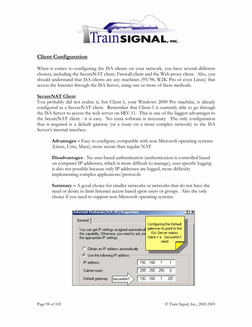
Page 98 of 102 © Train Signal, Inc., 2002-2003
Client Configuration When it comes to configuring the ISA clients on your network, you have several different choices, including the SecureNAT client, Firewall client and the Web proxy client. Also, you should understand that ISA clients are any machines (95/98, W2K Pro or even Linux) that access the Internet through the ISA Server, using one or more of these methods. SecureNAT Client You probably did not realize it, but Client-1, your Windows 2000 Pro machine, is already configured as a SecureNAT client. Remember that Client-1 is currently able to go through the ISA Server to access the web server on SRV-11. This is one of the biggest advantages to the SecureNAT client - it is easy. No extra software is necessary. The only configuration that is required is a default gateway (or a route on a more complex network) to the ISA Server’s internal interface.
Advantages – Easy to configure, compatible with non-Microsoft operating systems (Linux, Unix, Macs), more secure than regular NAT Disadvantages - No user-based authentication (authentication is controlled based on computer IP addresses, which is more difficult to manage), user-specific logging is also not possible because only IP addresses are logged, more difficulty implementing complex applications/protocols Summary – A good choice for smaller networks or networks that do not have the need or desire to limit Internet access based upon users or groups. Also the only choice if you need to support non-Microsoft operating systems.
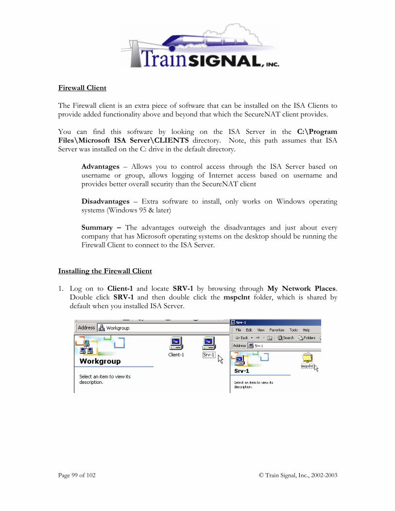
Page 99 of 102 © Train Signal, Inc., 2002-2003
Firewall Client The Firewall client is an extra piece of software that can be installed on the ISA Clients to provide added functionality above and beyond that which the SecureNAT client provides. You can find this software by looking on the ISA Server in the C:\Program Files\Microsoft ISA Server\CLIENTS directory. Note, this path assumes that ISA Server was installed on the C: drive in the default directory.
Advantages – Allows you to control access through the ISA Server based on username or group, allows logging of Internet access based on username and provides better overall security than the SecureNAT client Disadvantages – Extra software to install, only works on Windows operating systems (Windows 95 & later) Summary – The advantages outweigh the disadvantages and just about every company that has Microsoft operating systems on the desktop should be running the Firewall Client to connect to the ISA Server.
Installing the Firewall Client 1. Log on to Client-1 and locate SRV-1 by browsing through My Network Places.
Double click SRV-1 and then double click the mspclnt folder, which is shared by default when you installed ISA Server.

Page 100 of 102 © Train Signal, Inc., 2002-2003
2. Open the mspclnt folder and double click Setup.exe. Click Next on the initial screen and Next again to accept the default installation location. You can then click on Install to start the installation. Once the installation is complete you can click on Finish.
3. After the Firewall Client is installed you can check to see if it is running on your system
by verifying that the globe icon is located within your computer’s system tray.
4. Right click on the globe. From here you can disable the Firewall Client, hide the display
of the icon or configure the Firewall Client. Choose to Configure the Firewall Client. The following screen will be displayed, showing the ISA Server you are connected to and also allowing you to make other minor configuration changes.

Page 101 of 102 © Train Signal, Inc., 2002-2003
Web Proxy Client Although the web proxy client is listed as one of the ISA Server client options, it is actually an independent setting, and is configured in addition to either the SecureNAT client or the Firewall client. The Web Proxy Client can be configured within Internet Explorer or any CERN compatible browser (i.e. Netscape Navigator, Mozilla). The Web Proxy Client is important for authentication issues. If you have Site & Content Rules or Protocol Rules that do not specify specific users or groups (anyone is allowed access), then you should have no problem with not installing the Web Proxy Client. However, if you set up more specific Rules (i.e. “the Marketing Group can access HTTP” or “only certain computers can access the Internet during business hours”), then access will fail, and you will have to install the Web Proxy Client on all of your systems.
Advantages – Easy to configure (through Group Policy), when paired with the Firewall client provides complete authentication.
Disadvantages – Another setting to configure.
Summary – The web proxy client is important and should be utilized in almost every network. When combined with the Firewall client you are able to maximize ISA Server’s benefits.
Because it is fairly simple to configure and provides a lot of advantages, Green Lizard has decided to utilize the web proxy client within their network. 1. Log on to Client-1 and open Internet Explorer. Within Internet Explorer, click on
Tools Internet Options.

Page 102 of 102 © Train Signal, Inc., 2002-2003
2. Once the Internet Options are open, click on the Connections tab and then select LAN Settings at the bottom. On the LAN Settings screen, check the box Use a proxy server, and specify the IP address of SRV-1, 192.168.1.201. You also need to configure the Port, which by default is set at 8080 on the ISA Server. Click OK twice to exit the Internet Options screens.
Client-1 is now configured according to Green Lizard’s specifications. In a production environment, remember that the ideal solution is to configure your ISA clients as Firewall clients AND Web Proxy clients.