training
DESCRIPTION
trainingTRANSCRIPT

IIDD MMiiccrroommeetteerr CCaalliibbrraa iitt oonn RReeffeerreennccee CCaarrdd
1 . Inspect the micrometer visually as follows:
• Check for damage and excessive wear. • Check for smoothness of travel by rotating the
thimble throughout the range. • Check for worn contact points or end caps.
Ends should be spherical with no flat spots. • Check for slack in the spindle thread by
pushing the assembly in and out. Adjust to remove excessive play.
• Check all extension rods for straightness. • For tubular models: Verify both end caps are
the same diameter or within .0001”.
2. Clean both of the receiver pads and the
mounting surfaces of the flat face anvils using the cloth and ZEP I.D. Red cleaner.
3. Locate the right flat face anvil. Place the
shoulder side of the anvil against the right receiver pad shoulder.
Setup Materials Needed: • MIC TRAC MT-3000 base unit and CPU readout • 5/32" hex wrench • ID Micrometer • 30 in/lb torque wrench • Flat face anvils (TF-1F Blocks), cap screws and washers • Cloth • Micrometer & standards fixture (TF-SV Blocks) • ZEP I.D. Red cleaner
MIC TRAC MT-3000 1 1999 Gagemaker, Inc.
RCMIMT30009-99

IIDD MMiiccrroommeetteerr CCaalliibbrraa iitt oonn RReeffeerreennccee CCaarrdd
Setup 4. While holding the anvil against the receiver pad
shoulder, insert the two cap screws with washers into the holes on either side of the fixture.
5. While applying pressure toward the receiver
pad shoulder, use a 5/32" hex wrench to slightly tighten the screws.
6. Use a 30 in/lbs torque wrench to secure the
cap screws.
7. Repeat the same process with the left flat face
anvil, but before completely tightening the screws, be sure the anvils are aligned:
• Bring the flat face anvils together using the coarse adjust knob.
• While holding the anvils together with your fingers, move your finger back and forth along the backside of the anvils to verify alignment.
• If not aligned, loosen the left anvil and align. • Once aligned, use the torque wrench to secure
the left anvil.
8. Turn the coarse adjust knob counterclockwise
to bring the flat face anvils together. Set the measuring force, by pressing the INT (internal measurement) pad on the front panel of the CPU.
9. Press the ZERO pad on the CPU panel. The
readout displays P 0.0.
MIC TRAC MT-3000 2 1999 Gagemaker, Inc.
RCMIMT30009-99

IIDD MMiiccrroommeetteerr CCaalliibbrraa iitt oonn RReeffeerreennccee CCaarrdd
Setup
10. Turn the fine adjust knob counterclockwise until
the readout displays P 1.0.
11. Press the ZERO pad on the CPU panel. The
readout displays 0.00000. The measuring force is set to 1 lb. of force.
12. Locate the right micrometer & standards fixture.
With the thumbscrew facing forward, slide the micrometer fixture over the right flat face anvil until the cross brace touches the top of the flat face anvil.
Note: Be sure that the thin end of the “V-
groove” on the micrometer & standards fixture is on the inside face of the anvil.
13. While holding down the cross brace on the
micrometer & standards fixture, align the end of the micrometer & standards fixture 1/8” away from the inside face of the anvil. Tighten the thumb screw.
14. Repeat this process with the left micrometer &
standards fixture.
1/8 inch space
MIC TRAC MT-3000 3 1999 Gagemaker, Inc.
RCMIMT30009-99
IIDD MMiiccrroommeetteerr CCaalliibbrraa iitt oonn RReeffeerreennccee CCaarrdd
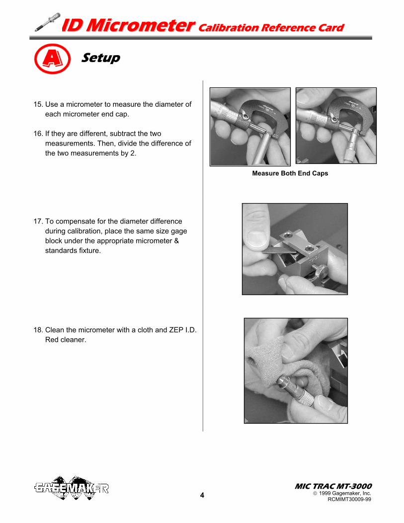
Setup 15. Use a micrometer to measure the diameter of
each micrometer end cap. 16. If they are different, subtract the two
measurements. Then, divide the difference of the two measurements by 2.
17. To compensate for the diameter difference
during calibration, place the same size gage block under the appropriate micrometer & standards fixture.
18. Clean the micrometer with a cloth and ZEP I.D.
Red cleaner.
Measure Both End Caps
MIC TRAC MT-3000 4 1999 Gagemaker, Inc.
RCMIMT30009-99

IIDD MMiiccrroommeetteerr CCa bbrraatt oonn RReeffeerreennccee CCaarrdd allii ii
MIC TRAC MT-3000 5 1999 Gagemaker, Inc.
RCMIMT30009-99
Materials Needed: • MIC TRAC MT-3000 base unit and CPU readout • 5/32" hex wrench • Seiko printer (optional) • Lightweight gage oil • ID Micrometer • Gage Calibration Record 1. Turn the micrometer spindle to the first
calibration value and lock. Note: If you pass the calibration value, turn the
spindle back and approach the value again, from the same direction. This practice will increase the accuracy of the calibration.
2. Using the coarse adjust knob, move the right
micrometer fixture closer to the left fixture. As the fixtures move closer together, place the end caps of the micrometer in the “V-groove” of each fixture.
3. Tighten the coarse adjust lock.
4. Turn the fine adjust knob clockwise until the PRINT light turns on. If you have a Seiko Printer attached to your MIC TRAC a permanent record of the measurement prints.
5. Record any deviations on the Gage Calibration
Record or in-house calibration report. 6. Continue measuring the micrometer until the
values for the first micrometer extension rod are complete.
7. Remove the micrometer, attach the next
extension rod, and continue with the same calibration process as the previous steps. Repeat the calibration for all remaining rods.
If using a computer with the MT-3000, go to page 7. Calibration

IIDD MMiiccrroommeetteerr CCaalliibbrraa iitt oonn RReeffeerreennccee CCaarrdd
Calibration 8. Remove the micrometer and continue with the
same calibration process for the next micrometer.
9. After calibrating all ID micrometers, be sure to
remove the micrometer & standards fixtures and flat face anvils from the MT-3000. Oil the fixtures and return them to the storage case.
MIC TRAC MT-3000 6 1999 Gagemaker, Inc.
RCMIMT30009-99

IIDD MMiiccrroommeetteerr CCa bbrraatt oonn RReeffeerreennccee CCaarrdd allii ii
If using a computer with the MT-3000, begin here.
Calibration
Materials Needed: • MIC TRAC MT-3000 base unit and CPU readout • ID Micrometer • Computer • 5/32" hex wrench • CALSPEX software • Lightweight gage oil • ComWin32 software • Brother P-Touch Label Printer (optional) 1. Start ComWin32 software by double clicking
the ComWin32 icon. The ComWin RS232 Handler window displays.
Note: This software allows the computer to
read the output from the serial port of the CPU.
2. Click the down arrow to select the proper
setting for the COM port the computer is using. For example, general2 is the setting for COM port 2.
Note: To have measured values from the
calibration recorded in CALSPEX, be sure that the box beside “Press Add to List Button” is selected.
3. Minimize ComWin32. This program must be
running while using CALSPEX.
4. Start CALSPEX by double clicking the
CALSPEX icon. 5. Click the New Calibration Report icon and the
Pick List window displays.
The gages available in the Pick List are those you have created yourself or gage types provided by CALSPEX.
ComWin32 Icon
CALSPEX Icon New Report Icon
MIC TRAC MT-3000 7 1999 Gagemaker, Inc.
RCMIMT30009-99

IIDD MMiiccrroommeetteerr CCaalliibbrraa iitt oonn RReeffeerreennccee CCaarrdd
Calibration 6. Select the ID micrometer from the Pick List. 7. Click the OK button. The Header Information
window displays for entering information about the company whose gage is being calibrated.
8 . Complete the following header information:
• Contact - name of person to contact regarding the gage.
• Department - department to which the gage belongs.
• PO/Account - purchase order or account number.
• Calibration Date - automatically displays, but can be changed by typing over the displayed date.
• Certified By - name of the person certifying the gage.
9. Click the Next button. The Gage Information
window displays.
10. Enter the following information about the gage
you are calibrating: • Control Number - unique identification
number for the gage. • Gage Manufacturer • Model • Serial Number • Description • Location
11. Click the Next button. The window for entering
gage inspection information displays.
MIC TRAC MT-3000 8 1999 Gagemaker, Inc.
RCMIMT30009-99

IIDD MMiiccrroommeetteerr CCaalliibbrraa iitt oonn RReeffeerreennccee CCaarrdd
Calibration 12. Inspect the ID micrometer and enter the results
of the inspection. 13. Click the Next button. The window for entering
beginning and ending calibration values displays.
14. Enter the beginning and ending calibration
measurements for the micrometer. 15. Click the Next button. The Tolerances window
displays.
16. Enter the tolerances for the micrometer. 17. Click the Next button. The calibration values
table window displays.
MIC TRAC MT-3000 9 1999 Gagemaker, Inc.
RCMIMT30009-99

IIDD MMiiccrroommeetteerr CCaalliibbrraa iitt oonn RReeffeerreennccee CCaarrdd Calibration 18. Turn the micrometer spindle to the first
calibration value. Note: If you pass the calibration value, turn the
spindle back and approach the value again, from the same direction. This practice will increase the accuracy of the calibration.
19. Using the coarse adjust knob, move the right
micrometer fixture closer to the left fixture. As the fixtures move closer together, place the end caps of the micrometer in the “V-groove” of each fixture.
20. Tighten the coarse adjust lock.
21. Enter the gage measurements in the Measured
column as follows:
• Turn the fine adjust knob clockwise until the measured value appears in the Measured column.
CALSPEX records the value and displays a green box in the In/Out column if the value is within tolerance. A red box displays if the value is not within tolerance. The Deviation column shows the deviation of the measured value from the master value.
MIC TRAC MT-3000 10 1999 Gagemaker, Inc.
RCMIMT30009-99

IIDD MMiiccrroommeetteerr CCaalliibbrraa iitt oonn RReeffeerreennccee CCaarrdd
MIC TRAC MT-3000 11 1999 Gagemaker, Inc.
RCMIMT30009-99
Calibration
22. Using each master value, continue measuring the micrometer until the values for the first micrometer extension rod are recorded in CALSPEX.
23. Remove the micrometer, attach the next
extension rod, and continue with the same calibration process as the previous step. Repeat the calibration for all remaining extension rods.
24. Click the Next button. The Next
Calibration/NIST window displays.
25. Change the Next Calibration Date, if
necessary, by typing over the displayed date. 26. Click the Next button. The Pass/Fail window
displays.
27. Click the Pass this Gage option or Fail this
Gage option to report the condition of the gage. You can pass a gage even if CALSPEX has determined that the gage measurements recorded are not within tolerance.
28. Click the Next button. The Save As window
displays.

IIDD MMiiccrroommeetteerr CCaalliibbrraa iitt oonn RReeffeerreennccee CCaarrdd Calibration Note: CALSPEX automatically assigns a filename
to each calibration. DO NOT change the filename to avoid problems with the CALSPEX database.
29. Click the Save button. The Gage Status
window displays.
30. Click the Update button to update the Recall
Database. Note: If you have a Brother P-Touch Label Printer
for printing calibration stickers, the Confirm window for printing a calibration tag displays.
31. If the Confirm window displays, click the Yes
button to print the Calibration Tag. Affix the Calibration Tag to the micrometer.
MIC TRAC MT-3000 12 1999 Gagemaker, Inc.
RCMIMT30009-99

IIDD MMiiccrroommeetteerr CCaalliibbrraa iitt oonn RReeffeerreennccee CCaarrdd Calibration 32. The Calibration Summary displays and shows
the calibration information for the micrometer. 33. Continue with the same calibration process for
the next micrometer.
34. After calibrating all ID micrometers, be sure to
remove the micrometer & standards fixtures and flat face anvils from the MT-3000. Oil the fixtures and anvils and return them to the storage case.
MIC TRAC MT-3000 13 1999 Gagemaker, Inc.
RCMIMT30009-99
