training in alternative energy technologies solar energy
TRANSCRIPT

TRAINING IN ALTERNATIVE ENERGY TECHNOLOGIES
Solar Energy Laboratory
University of Florida
Gainesville

(A.D. I.'
AGENCY FOR INTERNATIONAL DEVELOPMENT
TRAINING IN ALTERNATIVE ENERGY TECHNOLOGIES
(TAET)
Second Session
Sept. - Dec. 0980
GROUP PROJECT
DESIGN AND CONSTRUCTION OF SOLAR DISTILLATION PROTOTYPE
Ing. Oswaldo Proano B. Escuela Politecnica Nacional Quito - Ecuador
Ing. Guido Aspilcueta P. Electroperu (INI)
Limna, Peru
1980S .DECEMBER

Index
Subject Page
I Scope of the Project ............................................. 1
2. Introduction ..................................................... 2
3. Study of Design Variables ........................................ 4
3.1 Solar Radiation ............................................. 4
3.2 Depth of the Basin ........................................... 4
3.3 Cover Material and Its Shape and Orientation ................ 5
3.4 Ambient Temperature ......................................... 7
3.5 Wind Velocity ............................................... 7
3.6 Temperature of Condensing Surface ........................... 8
3.7 Type of Construction ........................................ 9
3.8 Materials of Construction .................................... 9
4. Components of a Solar Distillation Device ........................ 10
5. Heat and Mass Transfer Relationships ............................. 11
5.1 Equations ................................................... 11
5.2 Calculations ................................................. 13

6. Design and Construction of Apparatus ............................. 16
6.1 Sizing of Still Module ...................................... 16
6.2 Localization and Orientation ................................ 16
6.3 Materials of Construction Employed .......................... 16
6.4 Description of Constructed Apparatus ........................ 17
6.5 Different Steps in the Constrt~ction of Still ................ 18
7. Preliminary Experimentation ...................................... 20
7.1 Data for Surface Relations ................................... 20
7.2 Temperature Measurements .................................... 20
7.3 Solar Radiation Measurement .................................. 20
7.4 Wind Velocity Measurement ................................... 20
7.5 Procedure and Results ....................................... 21
8. Conclusions ...................................................... 22
9. Recommendations .................................................. 24
10. Bibliography ..................................................... 25

1. Scope of the Project
The purpose of this work is to design and construct a model of a
water desalination still with the cheapest and most common materials
available. The model also will be built with the minimum available
facilities. After the still is constructed, it will be tested to
determine its performance and efficiency.

2
2. Introduction
The water is the most abundant natural resource essential for human
life and human activities. The world is 2/3 parts water and the water
evaporates at the rate of 1.2 X 10¹⁷ gal per year. Of this quantity,
only I X 1016 gal are available for possible uses by life on earth and
7 X 10¹⁵ gal can be utilized. The present use is 7 X 10¹⁴ gal,
but the rate of rise of world population of 2% per annum makes the quantity
available for different uses insufficient for the year 2080.(0)
In conjunction with this factor is the fact that fresh water is not
available where it is needed or the reserves in some places are diminished
due to the local change of climactic conditions by the destruction of
natural forests and the problems of contamination in the industrial zones.
The resolution of this problem would be the transportation of water from
the rich zones to poor zones but the cost is high.
Another promising way is the desalination of water or the purification
of contaminated water. Actually, these methods are feasible utilizing
separation techniques like evaporation. The energy for evaporation is
supplied by fossil fuels and multistage flash evaporation is utilized.
The greatest desalination plants are located in the petroleum rich
countries. With the petroleum shortage it is natural to look for some
other methods of desalination in addition to distillation. These methods
are: reverse osmosis, electrolysis, freezing, etc.
Also there are other forms of energy to evaporate the water like:
solar energy, wind energy, biomass, etc. The solar energy is the most
promising and has been utilized for a long time in moderate evaporating
plants (less than 1,000 gal/day). The procedure is by direct absorption of
solar energy by water, successive evaporation and condensation of fresh

3
water.
Other indirect methods for capturing energy and for condensation in
multiple pass have been developed, but for plants of great capacity
(50,000 gal/day). Many studies were developed to understand the still
distillation phenomena, the performance of the still and the use of
different designs and materials in order to lower the cost of producing
fresh water.

4
3. Study of Design Variables
3.1 Solar Radiation
The quantity of energy received by a still changes with the
geographic location, with the prevalent weather, the month and the hour of
the day.
In the tropical countries the radiation is almost vertical but a great
variation of the climactic conditions exists, influenced by orographic and
hydrographic factors. For this reason the variation of sun radiation is
-irregular and less than in the other countries located in the temperate
zone.
From the data of the angle of solar incidence (which is calculated
from the known _..titude angle, tilted angle and the wall solar azimuth
angle), the angle factor and the diffuse factor it is feasible to estimate
the quantity of energy that is falling over a determinate place at any
month and hour of the day.
The experimental determination of solar radiation is done with a
calibrated pyranometer or pyroheliometer.
3.2 Depth of the Basins
The basins are generally shallow or deep. The shallow basins have a
profundity near 1 inch. The deep basins have a profundity near 10 inches.
The rate of evaporation in shallow basins is faster than in the deep
basins. This is expected since the heat transfer in a shallow basin is
very rapid and hence the productivity of deep basins is less than in the
shallow basins. The productivity of both types of basins decreases with
the increase of depth. (2)
In the deep basins an appreciable amount of solar radiation is

5
absorbed in the water due to the thermal capacity of the still. For this
reason, in this type of basin thL distillation continues overnight.
Meanwhile, in the shallow basins the distillation takes place during the
day. (3)
In addition, the thermal losses from the sides and bottom of the deep
basins tend to be larger than those of the shallow basins. The influence
of profundity in the deep basins is less marked than in shallow basins.
The shallow basins have other problems, like dry spots, blistering of
paints and deposition of salt, and thus require expensive maintenance. (4)
Another type of basin has been studied by several authors. This type
uses a wick where the evaporation takes place. The layer of water is very
thin (1/32 inch). However, there are several problems of salt clogging,
dry spots and brine flow control. (5) In practice, the yearly average
production of shallow basins is 0.7 lb/ft 2 day and for deep basins is
0.6 lb/ft 2 day.
In both types it is necessary to flush the basin in order to prevent
the salt deposition. The time of flushing for deep basins is generally 6
days and for shallow basins is generally 5 days.
3.3 Cover Material and its Shape and Orientation
The nature and properties of cover material are very important for a
design of a still because the cover lets the energy go through and it acts
like a condensing surface for hot water vapor produced inside the still..
The cover should transmit as much solar radiation as possible and the
resistance to heat transfer of condensation heat should be small. This
means that the thickness of the cover material should be very small and the
water film underside of the cover should be thin.
The cover material is generally glass or plastic. The glass sheets
have the advantages of high transmission of solar radiation, high
wettability and high stability of properties over extended periods of time.
The disadvantages are its relatively poor strength and thus, vulnerability
to mechanical damage. The plastic films are easily handled and have
relatively high transmission of solar incident radiation. At the same
time, they have high infrared transmittance of the radiation emitted by the
water surface. The plastic sheets also have high susceptibility tu
ultraviolet degradation which in conjunction with its low wettability make
this material unattractive in solar stills. (6)(7)
The slope of the cover is governed by three factors, namely: a) It
provide enough condensing surface for water vapor b) Its angle should be
such that it intercepts maximum solar radiation for the whole day c) The
spacing between the cover and water surface.
There are two types of roofs, the greenhouse or double slope and the
single slope cover with the south facing side normally having a reflective
surface. The two slope apparatus is more efficient than the one slope
apparatus especially in tropical countries. (8) It has been shown both
experimentally and theoretically that if enough condensing area is
available, the effect of spacing between cover and water surface is
negligible over productivity. (9)(10)(11) It also appears that the effect
of glass inclination on the amount of solar radiation entering the still is
small because the interception area is always horizontal except in the case
of a tilled wick. (12) Thus, the major factor governing the slope of the
cover is the availability of enough condensing area.
The orientation of the cover material in the northern hemisphere would
be E--W in the case of double slope because in the other direction, N-S,

7
the reflectivity increases. In the case of single slope, the orientation
would be E -W with the reflecting surface looking south. In the case of
countries located in the tropics the orientation is meaningless.
3.4 Ambient Temperature
The influence of ambient temperature over the solar output is
discussed by different authors; most of them express that the increment in
ambient temperature increases the efficiency of solar stills. This is
provided by an increase in water surface temperature, which increases the
rate of evaporation. (13)(14) The experimentation developed by Anil K.
Rajvanshi shows that a decrease in the ambient temperature by 20% increases
the distillate by 10.2%, while an increase in ambient temperature by 20%
decreases the output by 13.6%. It was explained that this was because the
condensation of distillate over the glass is primarily a function of a
tempeature difference between glass and ambient for the same outside heat
transfer coefficient.
It was pointed out that an increment of water surface temperature
results in an increase in ambient temperature, thereby increasing the
distillate output, but the temperature difference between the glass and the
water surface decreases with an increase in ambient temperature (the
driving potential for mass transfer).
3.5 Wind Velocity
The effect of wind velocity is important in the range of 0 to 25 mph.
This is because there is better heat transfer from the glass cover to the
ambient. An increase into the mentioned range increases the output by 10%.
However, with wind velocity above 25 mph, the output levels off. Tle

8
reason for this behavior is that at higher wind velocities, the limitation
on heat transfer is determined by the conductance of glass cover, not by
the outside heat transfer coefficient. (15)
It should be pointed out that there are conflicting results presented
in literature on the effect of wind velocity (13)(14)(16)(17)(18) However,
some computer simulation results do confirm the increase of productivity
with increasing wind velocities. (13)
3.6 Temperature of Condensing Surface
The temperature of the condensing surface is a function of brine
temperature and the ambient temperature. A great difference between these
two temperatures increases the productivity of the still. Many
investigators have tried to increase this difference by providing an
external condenser for water vapor like the blowing of air through the
still or fixing condensing surfaces into the still. (19)(20) Although
production as high as 0.22 gal/ft 2 day was reported, the additional cost
required to provide equipment more than offset the gain i' yield.
3.7 Type of Construction
In accordance with the criteria exposed in the items mentioned before,
different types of stills produce different outputs. The basic types of
basin are: deep, shallow or weak. The roof of this basin would be flat or
rounded. The brine vessel would be fixed under the ground or over the
ground affecting the heat transfer to the surroundings. A good
construction of still would avoid the leakages of the vessel and prevent
the release of vapor to the ambient. There are many studies developed on
this respect, but the most sophisticated designs are very expensive and

the shallow or deep basins with a flat inclined cover are until now the
most satisfactory design. (20)(21)
3.8 Materials of Construction
The still construction materials affect the performance. The cover of
the still is generally of glass or plastic, affecting the output like was
pointed out before. The materials of construction for the basin are:
wood, concrete, clay, fiberglass, stainless steel, butyl rubber, asphalt
and other kinds of plastics. The nature uf the material affects the
durability of the still.
The supporting materials are: wood, concrete, brick, aluminum, mild
steel, and stainless steel. The nature of the material also affects the
durability of the still. (6)

10
4. Components of a Solar Distillation Device
The device consists of a pool where the saline water is kept. This
pool is 1/2 inch to 3 ft deep. If the depth is near 1 inch it is called a
shallow basin, as was mentioned before.
The bottom of the basin is black to absorb solar energy and contains a
drain to discard brine continuously or periodically. The pool is insulated
to prevent heat losses to the surroundings. Above the basin is a sloping
transparent cover of glass or plastic sheet which acts as a condensing
surface. The cover is supported generally by a metallic structure.
The incident solar radiation after passing through the glass cover is
partially absorbed in the saline water, the major portion being absorbed in
the basin bottom. Heat is transferred to the water, thereby increasing the
temperature. Partial vaporization of the heated water thon occurs and
convection currents inside the still carry this vapor laden air to the
cooler glass cover. Moisture condenses on the underside of the cover. The
heat of condensation is taken out through the glass cover to the
surroundings and partially dehumidified air drifts back to the surface of
the water for further addition of moisture. The thin condensate film flows
down the cover into the collecting channels and is collected as a distilled
water.

5. Heat and Mass Transfer Relationships
The relationship to be utilized for the calculations are reviewed from
literature. (18)(22)
5.1 Equations
From Figure A it can be seen that the energy input to the still
comprises the radiation absorbed by the brine and trough system plus that
absorbed by the glass cover. The heat transfer to the surroundings is via
the glass cover and trough ground and walls. In the situation of
equilibrium conditions this may be as follows.
!X1 0 1 R
1 ( if'Ic o. JJ
w+,o - r.hweq. .' ct.w- ..
i -) -L - q t, ')
g) 4,1wi',: ! -
So)
7'4)

12
ag
T
Lw
Io
qg
qb
qr, qc
qe
a
tw, tg
Pw, Pwg
hw
(hc+r)a
ta
h
ca
Kb
AXb
ts
M .
=
=
=
=
=
=
=
=
=
=
=
=
=
=
=
solar absorptance of glass
solar transmittance of glass
solar absorptance of brine and trough system
2 hsolar radiation on horizontal surface, BTU/ft
heat transfer, glass cover to surroundings, BTU/h ft2
heat losses from the bottom and walls of the still, BTU/h ft2
heat transfer, brine to glass by radiation and convection,
iTU/h ft2
heat transfer, brine to glass by evaporation, BTU/h ft2
- 1 0 Stefan Boltzmann constant, 17.2 X 10 BTU/hr ft2
temperature of saline water and glass cover, °F
partial pressure of water vapor at tw, tg, psi
latent heat of vaporization of water at tw, BTU/lb
heat transfer coefficient for convection and radiation from
glass to the ambient, ETU/ft2 h
temperature of ambient, °F
heat transfer coefficient for convection from the glass to the
ambient, BTU/ft 2 h
heat transfer coefficient of conduction from the bottom and
walls to the ground, BTU/ft h OF
thickness of the ground involved in the heat transfer from the
bottom and walls to the ground, ft
final temperature of the ground to be considered in the heat
transfer from the bottom to the ground, OF
mass of water evaporated over an interval of time, lb
I 01
q=heat transfer, brine to glass by evaporation over an interval of
time, BTU/ft 2
= solar radiation on horizontal surface over an interval of time, BTU/ft 2
h c+r
= heat transfer coefficient for convection and radiation from water surface to the glass, BTU/ft 2 h
TI
he
=
=
efficiency of the solar still over an interval of time
heat transfer coefficient for evaporation, BTU/ft 2 h

13
5.2 Calculations
For the preliminary calculation it is feasible to use the following
data, which is taken from Gainesville conditions during the month of
December and from the literature. (1)(22) The relations between the
surface of the cover, the surface of the water and the surface of the heat
transfer to the ground are determined by the design conditions which will
be seen in the next chapter.
tw = 150'F (assumed initially)
ta = 750F
T = 0.7
a = 0.9 w
a = 0.1g
I0 = 300 BTU/h ft2
= 80°F (assumed)ts
Surface of water = 0.76 (the water fill the pool)
Surface of glass
Curface of bottom and walls = 1.9
Surface of glass
h = 2 BTU/h ft2 (assumed)c+r
(h )a = 3 BTU/h ft2 (assumed)c+r
he = 7 BTU/h ft2 (assumed)
AXb = 1.5 ft
Kb = 0.6 BTU/ft hi OF

14
From the equations: 2, 10, 11
r/t ,14-b)( KT )(o....)
' C- (,1C ,.€ t(o.-.,
2- C' - ./-'.:( c,.,--,0.)
The resolution of the system of equations gives:
From equation 1:
j~ ; X.z= j
(/eo.,)(?c )
+ cykv Z T.,
.,(L:.'U,,co ;)( ,r) "- i. C
From equation 7:
/AI (qj$w- ts")O1-.9)
5o.- (5s q) 14."
3 47r)(1/ -
15
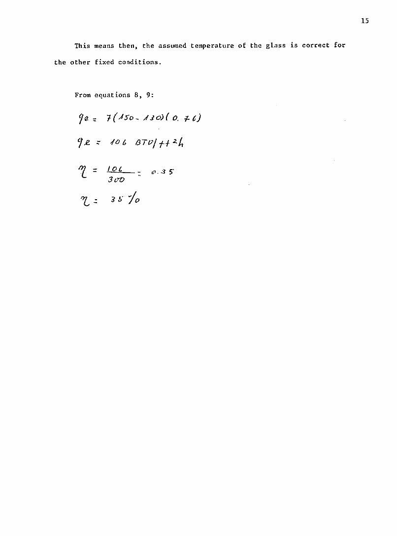
This means then, the assumed temperature of the glass is correct for
the other fixed coaditions.
From equations 8, 9:
i=. ( s-r - 03)C o . -)
3 OV

16
6. Design and Construction of Apparatus
In accordance with the criteria exposed before, the type of still to
be built is the deep basin. See Figure 1.
6.1 Sizing cf Still Module
The width of the basin was taken from the literatute data. The
principle criteria was the facility of manipulation in order to facilitate
the maintenance.
The longitude was taken in accordance with the availability of land
materials and time.
6.2 Localization and Orientation
The basin was located in the yard on the north side of the TREEO
building, near the wire fence.
The orientation of the basin was E-W because if the location were N-S,
there would be a great loss of incident light by reflection.
6.3 Materials of Construction Employed
The materials of construction employed were available in the
laboratory shop and consisted'of the following items.
A polyethylene, black, plastic sheet to cover the bottom and walls of
the pool..
Six wood poles each one 18" length, 3.5" width and 1.5" thickness.
In one end of the pole is a round cavity to hold the water collection
plastic tube.
Over the side of the same end is fixed a piece of metallic angle in
order to support the metallic structure.

17
The metallic structure consists of 6 pieces of 1" X 1" X 1/16"
aluminum angle. The length of each piece is 24". The mentioned pieces
conform to the sides of the triangular support structure, which are fixed
on the metallic pieces of angle located on the poles.
The triangular ends have bases consisting of pieces of aluminum angle
of 43" length. One piece of aluminum angle of 76" length is fixed along
the upper vertex of the triangular structure. This piece fixes and
completes the structure.
The channels to collect the water consist of half tubes of 3" diameter
PVC. The lengths of these tubes are 85". The channels are closed at both
ends by rounded plastic pieces. The channels have two holes in one side to
collect the rain and distilled water. Plastic tubes of 1/4" diameter are
ottached inside the holes to carry the water from the basin to the
collector flasks.
The glass cover, consisting of 4 pieces, 38" long and 24" wide, is
attached over the metallic structure. The glass thickness is 1/8".
The E-W ends of the structure are also covered with triangular pieces
of glass, 43" along the base and 24" along each side.
In Figure 2-3 it is possible to see the details of the construction
materials.
6.4 Description of Constructed Apparatus
The apparatus consists of the pool, the support structure and the
cover. The pool is 76" long, 38" wide and 12" high. The walls are
inclined. See Figure 2. The bottom is 62" long -nd 24" wide. Tle pool is
covered with a black plastic, which is prolonged outside.
The bottom of the pool is inclined in the E-W direction on about 1%

18
to facilitate the discharge. There are two holes inside the pool. The
first is located at the W end on the bottom and is crossed by a 1/2" iron
tube which allows drainage of the pool. The second is located at the E
wall of the pool and is crossed by a 3/4" rubber hose which allows the
feeding of the pool.
The structure is composed of aluminum angles and has a triangular
shape. The inclination angle is about 26.50.
The details about the structure are contained in Figures 2 and 3.
Lying over the structure is the cover of glass which consists of 4
pieces.
The poles are fixed inside the ground and have a rounded surface to
support the PVC collecting tubes. These tubes are inclined 1% to allow the
flow of collecting water.
Each tube has two holes at one end to let the collected water run out
of the basin through a plastic hose. The N-S ends of the glasses touch the
inner surfaces of the PVC discharging tubes and divide the tubes in two
sections. Over the lower section, the distilled water is collected and
over the upper section the rain water is collected. The collection of
distilled and rain water, as well as the drainage water from the basin, is
carried out through a hole dug near the still.
Details of the construction are in Figure 4-9.
6.5 Different Steps in the Construction of Still
The different steps of construction can be seen in Figure 4-9.
a) Location and orientation of still
b) Cleaning of selected area
c) Digging the holes for the pool of the basin and for
collecting water

19
Digging the holes for fixing the wood poles
d) Construction and fixing of wood poles
e) Construction and fixing of frame on the poles
f) Fixing the feeding and drainage tubes of the pool
g) Covering the basin with black plastic
h) Preparing and setting the collecting tubes over the poles
i) Sealing the black plastic along the tubes with plastic cement
j) Fixing the thermocouples inside the basin
k) Setting and sealing the glasses over the frame with silicon rubber
1) Sealing all the holes and leakages with silicon rubber

20
7. Preliminary Experimentation
7.1 Data for Surface Relations
Surface of Glasses: 25.3 ft2
Surface of Water: 15.3 ft2 (with a depth of 6")
Surface of heat transfer to the ground: 48 ft2
(For AXb = 1.5')
7.2 Temperature Measurements
The measure of temperature is effected by thermocouples located in
several points inside and outside the still, in accordance with the
following distribution:
1. Bottom
2. Inside water inferior level
3. Inside water superior level
4. Air-water space
5. Under glass
6. Upper glass
7. Ambient
The recordings are realized by a millivoltimeter.
7.3 Solar Radiation Measurement
The measure of solar radiation is effected by the pyroheliometer
Mark II.
7.4 Wind Velocity Measurement
The measure of wind velocity is effected by an anemometer.

21
7.5 Procedure and Results
The readings of temperatures, solar radiation and wind velocity were
taken each half hour. The readings began at 9 a.m. and ended at 3 p.m.
Out of this time, there was no incidence of solar radiation over the still.
The temperature measurements indicate that there was only a little heating
of water and the air inside the still attained a higher temperature than
the water. The measure of solar radiation indicates that in the south
glass surface the quantity of solar incident energy was larger than in the
north glass surface.
The wind velocity was less than 1 mph.
The small quantity of water collected was due to the distillation at
the end of the afternoon.

22
8. Conclusions
1. The principal purpose of this work, which is the design and
construction of a water desalination still model with the
cheapest and most common material available, has been
fulfilled.
2. The additional part of testing has not been done because of a
lack of time to make the test and the convenient rectifications.
3. The localization of the apparatus is bad because the trees near
the site make shadows and there is only incident sun light from
9 a.m. to 3 p.m. Besides, the site is a long way from
facilities like electricity and water.
4. The E-W orientation of the apparatus during the last months of
the year causes the surface facing to the south hotter than the
surface facing to the north.
5. The depth of the basin is about 12" and has a capacity of about
400 lb of water, which requires a great quantity of energy to
heat.
The bottom of the basin is slightly inclined to allow the
discharge of contained liquid, and has an inlet and an outlet.
6. The ground is covered with polyethylene black plastic sheet,
which was water proof tested. The lack of some kind of
insulation over the bottom and walls of the pool increases the
heat loss to the ground.
7. In the experimental conditions, a great portion of the basin
walls are not covered with water, making the energy losses
greater. There is a north wall shadow that covers about 50% of
the bottom surface, decreasing the incidence of sunlight.

23
8. The wood poles are completely fixed in the ground and give
support to the metallic structure and the discharging channels.
9. The aluminum angle structure is strong enough to resist the
weight of the glasses and adequate to secure them.
10. The channels of collection are 3" tubes of PVC cut in the
middle. The collection tubes lie over the rounded cavities of
the poles and have an inclination of 1%, to let the water run to
the outlets located in one of the ends. Each tube is touched by
the glasses, composing two collection sections; one for
distilled water and the other for rain water.
11. All the inside ends of the apparatus are sealed with plastic
cement to make it airtight.
The outside ends of the apparatus are covered with earth to
improve the seal of the apparatus.
12. The cover is composed of 4 glasses, which are lying over the
metallic structure. Also in the E and W ends are 2 triangular
pieces of glass to close the apparatus. The glasses are sealed
against the metallic frame with silicon rubber to make it
airtight.
13. Before attaching, the glasses were cleaned in the best way
possible, but there was still drop condensation.
14. All the steps of the still construction should be understood by
non-specialized personnel and the materials used should be
available everywhere.

24
9. Recommendations
1. It is necessary to determine the performance and efficiency of
the apparatus by means of broad experimentation, which is out of
the scope of the present work.
2. Before doing any experimental work, it is necessary to clean the
glasses in the best way and maybe to apply a substance to
improve the film condensation.
3. One set of tests should be done with different quantities of
water to find the minimum depth of water required to begin the
production of the still.
If the depth of water is small and near 1", it is better to
construct a shallow basin.
Another set of tests should be done to attach a different4.
thickness of insulation to the bottom and walls of the basin.
5. The apparatus should be tested in conditions of rainy weather to
collect rain water and to test the usefulness of the collection
channels.

25
10. Bibliography
1. Rajvanshi, Anil K. "Analytical and Experimental Investigation of the
Effect of Dyes on Solar Distillation", 1, Doctoral Thesis, University of Florida, Gainesville, Florida (1979).
2. Talbert, S.G., Eibling, J.A., L'f, 0.O.0., Wong, C. and Sieder, E.N. "Manual on Solar Distillation of Saline Water", Research and Development Program Report No. 546, United States Department of Interior, April (1970).
3. Malik, M.A.S. and Tron Van Vi "A Simplified Mathematical ModQl for
Predicting the Nocturnal Output of a Solar Still", Solar Energy, pp. 371 - 385, Volume 14, No. 4 (1973).
4. Howe, E.D. and Tleimat, B.M. "Twenty Years of Work on Solar Distillation at University of California", Solar Energy, 16, pp. 97 - 105 (1974).
5. Telkes, M. Re. rch on Methods for Solar Distillation, Research and Development Repl t No. 13, Office of Saline Water, United States Department of Interior (1956).
6. McCracken, Horace "Solar Still Pans, The Search for Inexpensive ;Ind Renewable Materials", Solar Energ., pp. 201 - 207, Volume 9, No. 4
(1968).
7. Tleimat, Badawi and Howe, Everett D. "Comparison of Plastic and Glass
Condensing Covers for Solar Distillers", Solar Energy, pp. 293 - 294,
Volume 12, No. 3 (1969).
8. Gomella, Cyril "Practical Possibilities for the Use of Solar
Distillation in Underdeveloped Arid Countries", Transactions of the
Conference on Solar Energy, 3, pp. 134 - 137, University of Arizona, Tucson (1955).
9. Bahadari, M.1.. and Edlin, F.E., "Improvement of the Solar Stills by
the Surface Treatment of the Glass", Solar Energy, pp. 339 - 352,
Volume 14, No. 3 (1973).
10. Satcunanathan, S. and Hansen, H.P. "An Investigation of Some of the
Parameters Involved in Solar Distillation", Solar Energy, pp. 353
363, Volume 14, No. 3 (1973).
11. Bloemer, J.W. "Factors Affecting Solar Still Performance", ASME,
Paper 65 - WAL Sol-1, 8 pages (1965).
12. Martens, C.P. "Theoretical Determination of Flux Entering Solar
Stills", Solar Energy, 10(2), pp. 77 - 80 (1966).
13. Cooper, P.I. "Digital Stimulation of Transient Solar Still
Processes", Solar Energy, pp. 313 - 331, Volume 12, No. 3 (1969).

26
14. Lof, G.O.0., Eibling, J.A. and Bloemer, J.W. "Energy Balances in Solar Distillers", AICHE Journal, 7(4), pp. 641 - 649 (1961).
15. Rajvanshi, Anil K. "Analytical and Experimental Investigation of the Effect of Dyes on Solar Distillation", 159, Doctoral Thesis, University of Florida, Gainesville, Florida (1979).
16. Howe, E.D. "Solar Distillation", Transactions of the Conference on Solar Energy, 3, pp. 159 - 169, University of Arizona, Tucson (1955).
17. Morse, R.N. and Read, W.R.W. "A Rational Basis for the Engineering Development of a Solar Still", Solar Energy, pp. 5 - 17, Volume 12, No. 1 (1968).
18. Soliman, S.HI. "Effect of Wind on Solar Distillation", Solar Energy, pp. 403 - 415, Volume 13, No. 4 (1972).
19. Greene, W.N., Hughes, R.B. and Thompson, T.L. "Operating Experiments with Natural and Forced Convection Solar Stills", Water and Sewage Work, 108, pp. 378 - 383 (1961).
20. Dunckle, R.V. "Solar Water Distillation: The Roof Type Still and A Multiple Effect Diffusion Still", International Developments in Heat Transfer, ASME, pp. 895 - 902 (1961).
21. Cooper, P.E. "Some Factors Affecting the Absorption of Solar Radiation in Solar Stills", Solar Energy, pp. 373 - 381, Volume 13, No. 4 (1972).
22. Raffat, Ali "Desalinization of Saline Water by Means of a Solar Still", pp. 49 - 60, Doctoral Thesis, University of Florida, Gainesville, Florida (1972).

Ifc A
HEIAT -LUXIES" IV A SOLAR ST ILL

. , 7 - . ... . .. f.... .. - . -..t . .
... .. _177
., ... ..- .._,. _...... ........ ... .. .......... ...................... .. .................. .......~~~~~~..................... . ....., ..:.F... Y .. .
, 7 ' ....... . ... .... . .. . ..
[7.......
17, 4 ........1-
. .. . .71..- 4 - :' . . . . .. . .. 4-... - , . !. . .. .•. . . . .. . . '. , .T.. . . . . . . . . .I. - . . .. -. . . ... .'T1- : . .. .. . .
.1.1. .- 4
- -I T11 . ,1,2+'.. - : F - .4 1L .1, 4-,-r-. rrj-. ..- .... . . - ;- I , ... -.-. ...
... .... .r.. .. . . . . , . .. . .. *1 :,.V i-.. 2i "" . . .. FT . . .. ,.---{
i <LiU7t2.~.t- ... ,. .4 It. ,IT---.:Tt~; .. - .- -- . . , ,, . , . - + . . .. . . .t. . .. . ... .:::. .. .... [ .- - - i .f...,; - - T:.. . ... ....TS.. ==-::: :"Nq i'-'~~~~~~~~~~~~~~~~~_'-. "-"": -- ' -2: , , . ,, . : . . .4.,7,
iT Ia Ft;Y.7"!V~i71.+" ''+j I 7 .. ..t7: ... , :-.,._T _. . .,_ "...".
= ' t . . ;:":_T ~ - - . .. 1T I 4.--.-rl;
T ,r,.. Z-IT,, _..... . -4... _,_m ,
..... ..... ,. ... .. .. .. .. ... .. ...,.. .. .. .. . _.T7tt.L, , ...... .1 2-4447t414....~ 4. .:.~~~~~~i~$ .................... ..
,_ 4 t 44-, . .- ._:_. .____... __...__7,7_. La7.:::: 7_:____..
r 4 Tr4IIy1~~~~4
I-I44T T:~t~~ 4~4. 1 I

T4 l 4=4
-'- 7r.1'-, -rr ,
pI
o .. . ,
o 44
.,...... *...
-t
, - .. .I-,
-1
I - - . .. , ,.-"-
77
.... . -...
--F4~
. .. ... .... 1 ............ ... ... :.... . ....
'JJ
, ...
- . . . , VI~~
- - -..-.
'4 4.
Hi___I______7
S- .. ... .. .. .. ..
-774
___ _______T____4
I IT__-__._1 __"___________ _777:____T':hT
|~~ ~
[................... ... r'-.
~ ~ ~ ~ . ..
..... -:i ........... I.'- ~ 1-, 1-
~
!.
' L.
" - . ..'
~......~~~7:
;-..I . . ,
-
.....
I
.. Ii
1
?
BlA K
TF.
4 -.7..~If
. ..
-.TI'.-..l..-....:I::..
I.- I: ;, : ,4,l: :; 7.r~7:L'fJT1::;:.,
-
,:-II ;......I.,. .
-777r -1
....
1.2
.7
.. . . . . . .
. .... . . .......... ,.... .......
......
i ... :--t---I ......!? .......... .. . • • .. .., . -- :!. - -,.I... .. ........
" = = = = = = = = =" " ' ! : ' " : l : " : - ! i ' = = = _1i i i. _P:. . 1 :;: ! ; : . ! : ; ! . ; : P. t - . ; : : : : ' : : !
: 7i : 7- j,-:!' -*;I, , , . : ; ' *. I -I . _ . _

...... JTV4T71 ZVc. vaC1. .. .e~"
.. ..:-;....:' '1E.T4/// O ,. - t. ¢ 'g....--T----'t-...-.I ...... ..... ... "..K " :,:"....
- :... .. .;.. ... ..... . . . .. -i. ..
Ti6r
.. .".. ... .
X'
-- -- --- .. .. - ... . . . ...
Ac1,VC7..
..- .. .. 4 - - - '.
s Q __ _ .--- ~ 7 ~ ~
-T
'17._.. \4
. .. ......., f.. -
""* .. .t ".. .. i- r ' . . . . . .. ... .. ..... ....._ _
-
,.4F
_
1.
_ _-LK
. . . .4
_ . . . .
44,1

F14. .
* t ba

---
., " " ,/,."-' " .: - ". ";'
:F16- 7-,
P) 1

4 -'
F16.
77
t7,2