training material heat exchangers
TRANSCRIPT
Basics of Shell & Tube Heat Exchangers
Introduction
Shell and tube heat exchangers represent the most widely used vehicle for the transfer of
heat in industrial process applications. They are frequently selected for such duties as:
• Process liquid or gas cooling
• Process or refrigerant vapor or steam condensing
• Process liquid, steam or refrigerant evaporation
• Process heat removal and preheating of feed water
• Thermal energy conservation efforts, heat recovery
• Compressor, turbine and engine cooling, oil and jacket water
• Hydraulic and lube oil cooling
• Many other industrial applications
Shell and tube heat exchangers have the ability to transfer large amounts of heat in
relatively low cost, servicable designs. They can provide large amounts of effective tube
surface while minimizing the requirements of floor space, liquid volume and weight.
Shell and tube exchangers are available in a wide range of sizes. They have been used in
industry for over 150 years, so the thermal technologies and manufacturing methods are
well defined and applied by modern competitive manufacturers. Tube surfaces from
standard to exotic metals with plain or enhanced surface characteristics are widely

available. They can help provide the least costly mechanical design for the flows, liquids
and temperatures involved.
There are two distinct types of shell and tube heat exchangers, based in part on shell
diameter.
1) Designs from 2. to around 12. in shell diameter are available that feature shell
constructions of low cost welded steel, brazed pipe with hub forgings, cast end
bonnets and copper tubing rolled or brazed to the tube sheet. This mass
production product has had great success with OEM.s of industrial machinery for
oil cooling and water to water applications.
2) The other major type of shell and tube heat exchanger generally is seen in shell
diameters from 10. to over 100.. Commonly available steel pipe is generally used
up to 24. in diameter. Above 24., manufactures use rolled and welded steel plate,
which is more costly and roundness can become an issue. Heat exchangers of this
type are commonly manufactured to the standards set forth by TEMA, the
Tubular Exchangers Manufacturers Association. TEMA, in cooperation with
users and manufacturers, establishes a common set of guidelines for the
construction methods, tolerances and practices to be employed. This allows
industrial consumers to obtain more than one manufacturers offerings and know
that they are generally of similar design and construction. Additionally, it allows
manufactures to establish industry approved designs and offer state of the art
equipment that help to assure competitiveness and overall product reliability.

Although there exists a wide variety of designs and materials available, there are
components common to all designs. Tubes are mechanically attached to tube sheets,
which are contained inside a shell with ports for inlet and outlet fluid or gas. They are
designed to prevent liquid flowing inside the tubes to mix with the fluid outside the tubes.
Tube sheets can be fixed to the shell or allowed to expand and contract with thermal
stresses by have one tube sheet float inside the shell or by using an expansion bellows in
the shell. This design can also allow pulling the entire tube bundle assembly from the
shell to clean the shell circuit of the exchanger.
Note:
Since the inception of the 2007 Edition of the ASME Section VIII, Division 1 code, the
Heat Exchangers are required to be mandator designed as per the Appendix – UHX of
the code.
Components
The principal components of a Shell & Tube Heat Exchanger are:
shell;

shell cover;
tubes;
channel;
channel cover;
tube-sheet;
baffles; and
nozzles.
Other components include tie-rods and spacers, pass partition plates, impingement plate,
longitudinal baffle, sealing strips, supports, and foundation.
An STHE is divided into three parts:
a) the front head,
b) the shell, and
c) the rear head.
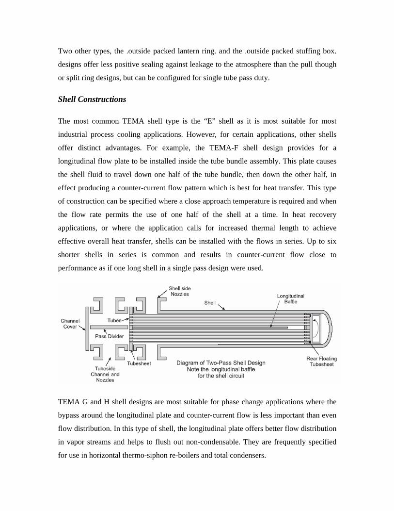
The below shown Figure illustrates the TEMA nomenclature for the various construction
possibilities. Exchangers are described by the letter codes for the three sections — for
example, a BFL exchanger has a bonnet cover, a two-pass shell with a longitudinal
baffle, and a fixed-tube-sheet rear head.


Fluid Stream Allocations
There are a number of practical guidelines which can lead to the optimum design of a
given heat exchanger. Remembering that the primary duty is to perform its thermal duty
with the lowest cost yet provide excellent in service reliability, the selection of fluid
stream allocations should be of primary concern to the designer. There are many trade-
offs in fluid allocation in heat transfer coefficients, available pressure drop, fouling
tendencies and operating pressure.
1) The higher pressure fluid normally flows through the tube side. With their small
diameter and nominal wall thicknesses, they are easily able to accept high
pressures and avoids more expensive, larger diameter components to be designed
for high pressure. If it is necessary to put the higher pressure stream in the shell, it
should be placed in a smaller diameter and longer shell.
2) Place corrosive fluids in the tubes, other items being equal. Corrosion is resisted
by using special alloys and it is much less expensive than using special alloy shell
materials. Other tube side materials can be clad with corrosion resistant materials
or epoxy coated.
3) Flow the higher fouling fluids through the tubes. Tubes are easier to clean using
common mechanical methods.
4) Because of the wide variety of designs and configurations available for the shell
circuits, such as tube pitch, baffle use and spacing, multiple nozzles, it is best to
place fluids requiring low pressure drops in the shell circuit.
5) The fluid with the lower heat transfer coefficient normally goes in the shell
circuit. This allows the use of low-fin tubing to offset the low transfer rate by
providing increased available surface.

Tubes
Tubing that is generally used is made from low carbon steel, copper, Admiralty, Copper-
Nickel, stainless steel, Hastalloy, Inconel, titanium and a few others. It is common to use
tubing from 5/8. to 1-1/2. in these designs. Tubes are either generally drawn and seamless
or welded. High quality ERW (electro-resistance welded) tubes exhibit superior grain
structure at the weld. Extruded tube with low fins and interior rifling is specified for
certain applications. Surface enhancements are used to increase the available metal
surface or aid in fluid turbulence, thereby increasing the effective heat transfer rate.
Finned tubing is recommended when the shell side fluid has a substantially lower heat
transfer coefficient than the tube side fluid. Finned tubing has an outside diameter in the
finned area slightly under the un-finned, or landing area for the tube sheets. This is to
allow assembly by sliding the tubes through the baffles and tube supports while
minimizing fluid bypass.
U-tube designs are specified when the thermal difference of the fluids and flows would
result in excessive thermal expansion of the tubes. U-tube bundles do not have as much
tube surface as straight tube bundles, due to the bending radius, and the curved ends
cannot be easily cleaned. Additionally, interior tubes are difficult to replace, many times
requiring the removal of outer layers, or simply plugging the tube. Because of the ease in
manufacturing and service, it is common to use a removable tube bundle design when
specifying U-tubes.
Tubesheets
Tubesheets are usually made from a round flat piece of metal with holes drilled for the
tube ends in a precise location and pattern relative to one another. Tube sheet materials
range as tube materials. Tubes are attached to the tube sheet by pneumatic or hydraulic

pressure or by roller expansion. Tube holes can be drilled and reamed and can be
machined with one or more grooves. This greatly increases the strength of the tube joint.
The tubesheet is in contact with both fluids and so must have corrosion resistance
allowances and have metallurgical and electrochemical properties appropriate for the
fluids and velocities. Low carbon steel tube sheets can include a layer of a higher alloy
metal bonded to the surface to provide more effective corrosion resistance without the
expense of using the solid alloy.
The tube hole pattern or “pitch” varies the distance from one tube to the other and angle
of the tubes relative to each other and to the direction of flow. This allows the
manipulation of fluid velocities and pressure drop, and provides the maximum amount of
turbulence and tube surface contact for effective heat transfer. Where the tube and tube
sheet materials are joinable, weldable metals, the tube joint can be further strengthened
by applying a seal weld or strength weld to the joint. A strength weld has a tube slightly
recessed inside the tube hole or slightly extended beyond the tube sheet. The weld adds
metal to the resulting lip. A seal weld is specified to help prevent the shell and tube
liquids from intermixing. In this treatment, the tube is flush with the tube sheet surface.
The weld does not add metal, but rather fuses the two materials. In cases where it is
critical to avoid fluid intermixing, a double tube sheet can be provided. In this design, the
outer tube sheet is outside the shell circuit, virtually eliminating the chance of fluid
intermixing. The inner tube sheet is vented to atmosphere so any fluid leak is easily
detected.
Shell Assembly
The shell is constructed either from pipe up to 24. or rolled and welded plate metal. For
reasons of economy, low carbon steel is in common use, but other materials suitable for
extreme temperature or corrosion resistance are often specified. Using commonly
available shell pipe to 24. in diameter results in reduced cost and ease of manufacturing,
partly because they are generally more perfectly round than rolled and welded shells.
Roundness and consistent shell ID is necessary to minimize the space between the baffle
outside edge and the shell as excessive space allows fluid bypass and reduced
performance. Roundness can be increased by expanding the shell around a mandrel or
double rolling after welding the longitudinal seam. In extreme cases the shell can be cast
and then bored to the correct ID.
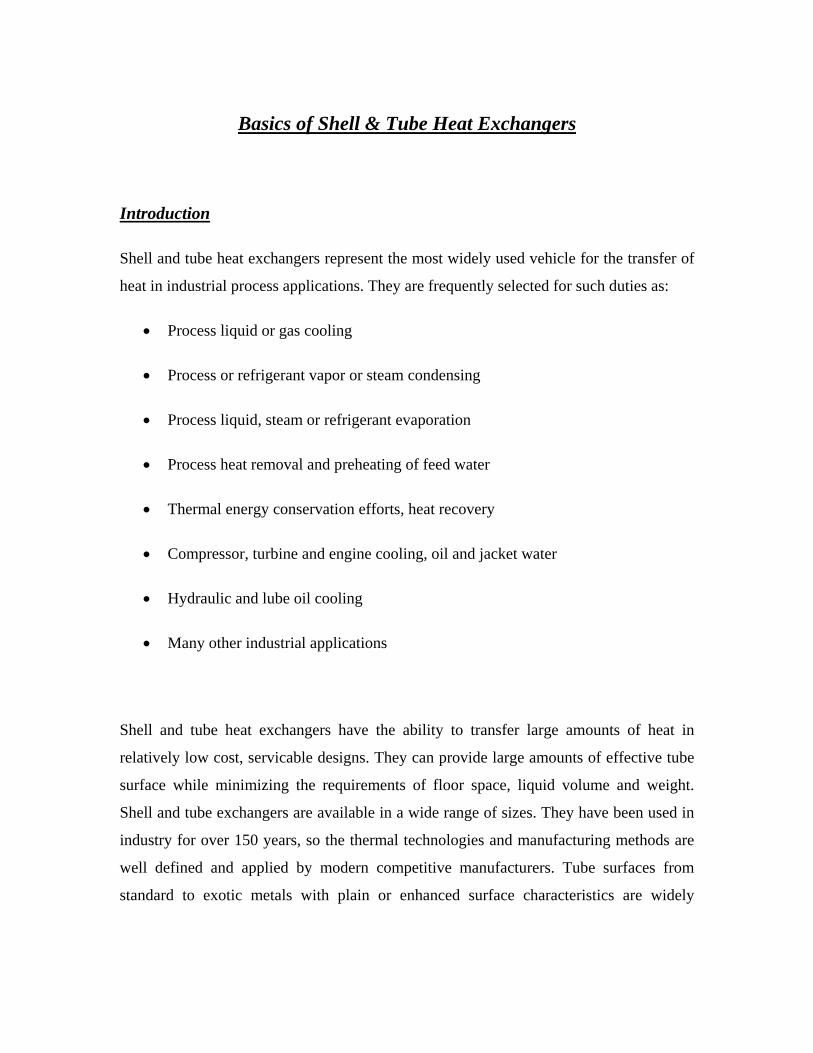
In applications where the fluid velocity for the nozzle diameter is high, an impingement

plate is specified to distribute the fluid evenly to the tubes and prevent fluid induced
erosion, cavitation and vibration. An impingement plate can be installed inside the shell,
which prevents installing a full tube bundle, resulting in less available surface. It can
alternately be installed in a domed area above the shell. The domed area can either be
reducing coupling or a fabricated dome. This style allows a full tube count and therefore
maximizes the utilization of shell space.
End Channels and Bonnets
End channels or bonnets are typically fabricated or cast and control the flow of the
tubeside fluid in the tube circuit. They are attached to the tube sheets by bolting with a
gasket between the two metal surfaces. In some cases, effective sealing can be obtained
by installing an O-ring in a machined groove in the tube sheet.
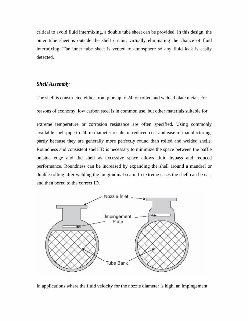
The head may have pass ribs that dictate if the tube fluid makes one or more passes
through the tube bundle sections. Front and rear head pass ribs and gaskets are matched
to provide effective fluid velocities by forcing the flow through various numbers of tubes
at a time. Generally, passes are designed to provide roughly equal tube-number access
and to assure even fluid velocity and pressure drop throughout the bundle. Even fluid
velocities also affect the film coefficients and heat transfer rate so that accurate prediction
of performance can be readily made. Designs for up to six tube passes are common. Pass
ribs for cast heads are intregrally cast and then machined flat. Pass ribs for fabricated
heads are welded into place. The tube sheets and tube layout in multi-pass heat
exchangers must have provision for the pass ribs. This requires either removing tubes to
allow a low cost straight pass rib, or machining the pass rib with curves around the tubes,
which is more costly to manufacture. Where a full bundle tube count is required to satisfy
the thermal requirements, this machined pass rib approach may prevent having to
consider the next larger shell diameter.
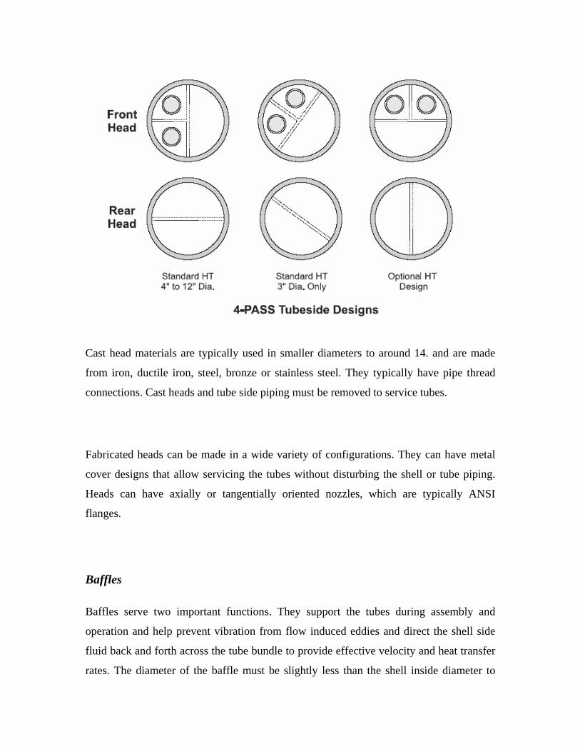
Cast head materials are typically used in smaller diameters to around 14. and are made
from iron, ductile iron, steel, bronze or stainless steel. They typically have pipe thread
connections. Cast heads and tube side piping must be removed to service tubes.
Fabricated heads can be made in a wide variety of configurations. They can have metal
cover designs that allow servicing the tubes without disturbing the shell or tube piping.
Heads can have axially or tangentially oriented nozzles, which are typically ANSI
flanges.
Baffles
Baffles serve two important functions. They support the tubes during assembly and
operation and help prevent vibration from flow induced eddies and direct the shell side
fluid back and forth across the tube bundle to provide effective velocity and heat transfer
rates. The diameter of the baffle must be slightly less than the shell inside diameter to
allow assembly, but must be close enough to avoid the substantial performance penalty
caused by fluid bypass around the baffles. Shell roundness is important to achieve
effective sealing against excessive bypass. Baffles can be made from a variety of
materials compatible with the shell side fluid. They can be punched or machined. Some
baffles are made by a punch which provides a lip around the tube hole to provide more
surface against the tube and eliminate tube wall cutting from the baffle edge. The tube
holes must be precise enough to allow easy assembly and field tube replacement, yet
minimize the chance of fluid flowing between the tube wall and baffle hole, resulting in
reduced thermal performance and increased potential for tube wall cutting from vibration.
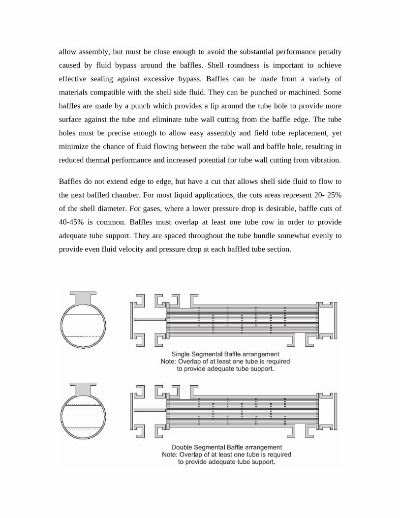
Baffles do not extend edge to edge, but have a cut that allows shell side fluid to flow to
the next baffled chamber. For most liquid applications, the cuts areas represent 20- 25%
of the shell diameter. For gases, where a lower pressure drop is desirable, baffle cuts of
40-45% is common. Baffles must overlap at least one tube row in order to provide
adequate tube support. They are spaced throughout the tube bundle somewhat evenly to
provide even fluid velocity and pressure drop at each baffled tube section.
Single-segmental baffles force the fluid or gas across the entire tube count, here is
changes direction as dictated by the baffle cut and spacing. This can result in excessive
pressure loss in high velocity gases. In order to effect heat transfer, yet reduce the
pressure drop, double-segmental baffles can be used. This approach retains the structural
effectiveness of the tube bundle, yet allows the gas to flow between alternating sections
of tube in a straighter overall direction, thereby reducing the effect of numerous changes
of direction. This approach takes full advantage of the available tube surface but a
reduction in performance can be expected due to a reduced heat transfer rate. Because
pressure drop varies with velocity, cutting the velocity in half by using double segmental
baffles results in roughly 1/4 of the pressure drop as seen in a single-segmental baffle
space over the same tube surface.
TEMA Designations
Because of the number of variations in mechanical designs for front and rear heads and
shells, and for commercial reasons, TEMA has designated a system of notations that
correspond to each major type of front head, shell style and rear head. The first letter
identifies the front head, the second letter identifies the shell type and the third letter
identifies the rear head type.
Differential Thermal Expansion
Since the duty of heat exchangers includes the handling of fluids of differing temperature,
flow rate and thermal properties, differential expansion of the metals will take place.
When the terminal temperature difference between the fluids is substantial, over 50-60
degrees, these stresses can become severe, causing shells to become deformed and
damage mounting supports, tubes to deform the tube sheet or tubes to become broken or
dislodged from the tube sheet. Fixed tube sheet designs are most vulnerable to differential
thermal expansion, because there is no inherent provision to absorb the stresses. One
approach in common use is installing an expansion joint in the shell pipe of such designs.
This is a cost effective approach for pipe-size shells. An expansion joint can also be
installed in the tube side of floating head designs, but manufacturing costs are much
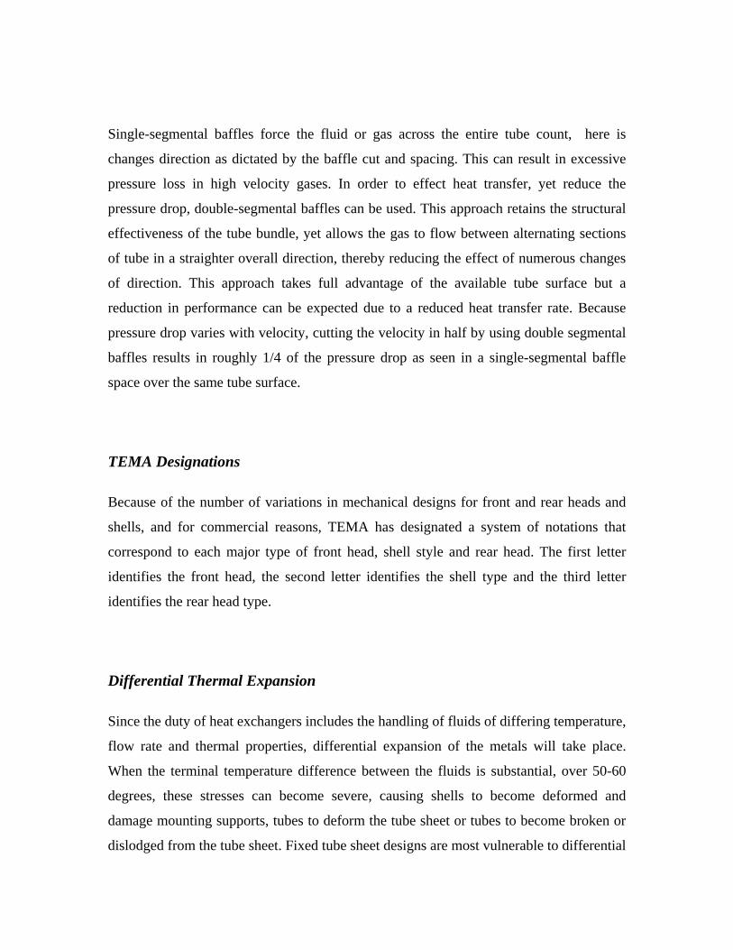
higher. Alternative approaches involve the design of a U-tube bundle so that each tube
can independently expand and contract as needed or by using a rear floating internal tube
sheet design which allows the entire bundle as a unit to expand and contract. The floating
head is typically sealed against the interior of the shell by means of packing or O-ring
designs.
U-tube designs while offering the best answer for differential thermal expansion, have
some drawbacks. Individual tubes can be difficult of expensive to replace, especially for
interior tubes. Also, the tube interior cannot be effectively cleaned in the u-bends.
Erosion damage is also frequently seen in the u-bends in high tube side velocity
applications. In large diameter shells, the long length of unsupported tube in the u-bends
of outer tubes can lead to vibration induced damage.
Floating Head Designs
In an effort to reduce thermal stresses and provide a means to remove the tube bundle for
cleaning, several floating rear head designs have been established. The simplest is a .pull-

through. design which allows the tube bundle to be pulled entirely through the shell for
service or replacement. In order to accommodate the rear head bolt circle, tubes must be
removed resulting in a less efficient use of shell size. In addition, the missing tubes result
in larger annular spaces and can contribute to reduced flow across the effective tube
surface, resulting in reduced thermal performance. Some designs include sealing strips
installed in the shell to help block the bypass steam. Another floating head design that
partially addresses the above disadvantages is a .split-ring floating head. Here the floating
head bonnet is bolted to a split backing ring instead of the tube sheet. This eliminates the
bolt circle diameter and allows a full complement of tubes to fill the shell. This
construction is more expensive than a common pull through design, but is in wide use in
petrochemical applications. For applications with high pressures or temperatures, or
where more positive sealing between the fluids is desired, the pull-through design should
be specified.
Two other types, the .outside packed lantern ring. and the .outside packed stuffing box.
designs offer less positive sealing against leakage to the atmosphere than the pull though
or split ring designs, but can be configured for single tube pass duty.
Shell Constructions
The most common TEMA shell type is the “E” shell as it is most suitable for most
industrial process cooling applications. However, for certain applications, other shells
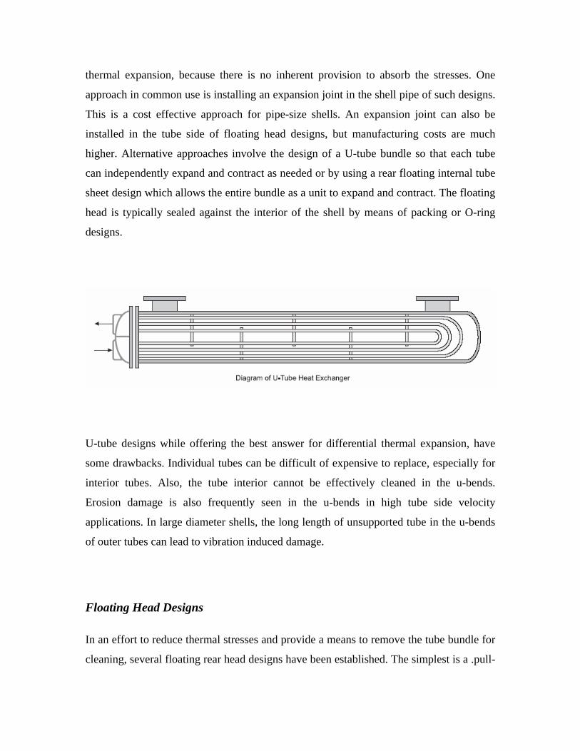
offer distinct advantages. For example, the TEMA-F shell design provides for a
longitudinal flow plate to be installed inside the tube bundle assembly. This plate causes
the shell fluid to travel down one half of the tube bundle, then down the other half, in
effect producing a counter-current flow pattern which is best for heat transfer. This type
of construction can be specified where a close approach temperature is required and when
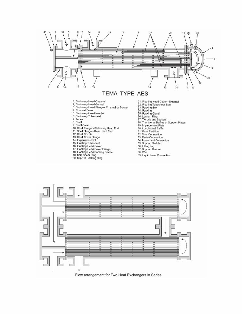
the flow rate permits the use of one half of the shell at a time. In heat recovery
applications, or where the application calls for increased thermal length to achieve
effective overall heat transfer, shells can be installed with the flows in series. Up to six
shorter shells in series is common and results in counter-current flow close to
performance as if one long shell in a single pass design were used.
TEMA G and H shell designs are most suitable for phase change applications where the
bypass around the longitudinal plate and counter-current flow is less important than even
flow distribution. In this type of shell, the longitudinal plate offers better flow distribution
in vapor streams and helps to flush out non-condensable. They are frequently specified
for use in horizontal thermo-siphon re-boilers and total condensers.
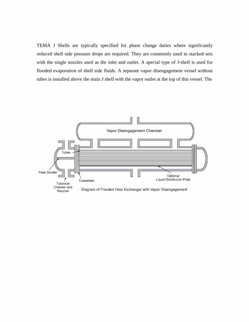
TEMA J Shells are typically specified for phase change duties where significantly
reduced shell side pressure drops are required. They are commonly used in stacked sets
with the single nozzles used as the inlet and outlet. A special type of J-shell is used for
flooded evaporation of shell side fluids. A separate vapor disengagement vessel without
tubes is installed above the main J shell with the vapor outlet at the top of this vessel. The

TEMA K shell, also termed a .kettle reboiler, is specified when the shell side stream will
undergo vaporization. The liquid level of a K shell design should just cover the tube
bundle, which fills the smaller diameter end of the shell. This liquid level is controlled by
the liquid flowing over a wier at the far end of the entrance nozzle. The expanded shell
area serves to facilitate vapor disengagement for boiling liquid in the bottom of the shell.
To insure against excessive liquid carry-though with the vapor stream, a separate vessel
as described above is specified. Liquid carry-through can also be minimized by installing
a mesh demister at the vapor exit nozzle. U-bundles are typically used with K shell
designs. K shells are expensive for high pressure vaporization due to shell diameter and
the required wall thickness.