training paper on power factor correction
TRANSCRIPT
8/13/2019 Training Paper on Power Factor Correction
http://slidepdf.com/reader/full/training-paper-on-power-factor-correction 1/32
Power factor correction
What is Power factor?
Power Factor = Active Power (kW)/Apparent Power (kVA)
And kVA = √ kW2 + kVAr
2
• Hence Power Factor can never be greater than 1.00
• Power Factor at best can be equal to 1.00
• Usually P.F is always “Lag” (Inductive): This is because in any Industry, themajority of the Loads (for e.g. Induction Motors, etc.) are inductive in nature andconsume reactive power to meet their magnetic field requirements.
• Some times P.F can be “Lead” (Capacitive): This situation normally arises whenthere are excessive capacitors in the installation compared to actual kVAr
requirement of the Inductive Loads in the installation.
Why power factor is important?
Low Power Factor means
• Inefficient use of Electrical Energy:
• Overloading of Transformer/Generator;
• Overloading of Cable, Switchgear, Busbar …
• Higher temperature due to increased losses
• Imposes larger kVA demand• Limits No. of loads that can be connected
• Reduced revenue to Electrical Utilities
• Poor Voltage regulation
Why improve power factor?
• Avoid power factor penalties
• Reduction in current drawn
• Reduction in line losses
• Enables more load to be connected
• Reduction in kVA Demand
• Increased life of Electrical Equipment
• More revenue to Utilities
• Improved Voltage regulation
Insert page 23 from LV manual.

8/13/2019 Training Paper on Power Factor Correction
http://slidepdf.com/reader/full/training-paper-on-power-factor-correction 2/32
What is the power factor of various loads?
• Incandescent Lamps - 1.00
• Resistive Heaters - 1.00
• Induction Motors - 0.7 to 0.85
• Fluorescent Lighting - 0.6
• Compact Fluorescent - < 0.9 lead
• Computers - < 0.9 lead
• Induction Furnace - 0.7 to 0.8
What is the origin of power factor?
• Electrical Equipment need Reactive Power
• Inductive loads draw Reactive Power
• Phase difference between current & Voltage• Reactive Power to maintain magnetic fields
in Motors.
8/13/2019 Training Paper on Power Factor Correction
http://slidepdf.com/reader/full/training-paper-on-power-factor-correction 3/32
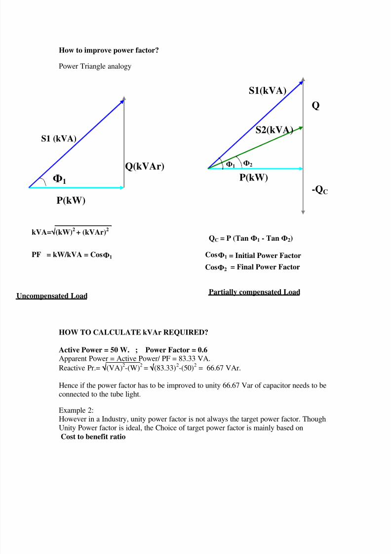
How to improve power factor?
Power Triangle analogy
HOW TO CALCULATE kVAr REQUIRED?
Active Power = 50 W. ; Power Factor = 0.6 Apparent Power = Active Power/ PF = 83.33 VA.
Reactive Pr.= √√√√(VA)2-(W)
2= √√√√(83.33)
2-(50)
2 = 66.67 VAr.
Hence if the power factor has to be improved to unity 66.67 Var of capacitor needs to beconnected to the tube light.
Example 2:However in a Industry, unity power factor is not always the target power factor. Though
Unity Power factor is ideal, the Choice of target power factor is mainly based on
Cost to benefit ratio
1 Q(kVAr)
P(kW)
S1 (kVA)
1
P(kW)
S1(kVA)
2
Q
-QC
QC = P (Tan 1 - Tan 2)kVA=√√√√(kW)
2+ (kVAr)
2
PF = kW/kVA = Cos 1 Cos1
2Cos
= Initial Power Factor
= Final Power Factor
Uncompensated Load Partially compensated Load
S2(kVA)
8/13/2019 Training Paper on Power Factor Correction
http://slidepdf.com/reader/full/training-paper-on-power-factor-correction 4/32
The cost to benefit ratio is subjective to the tariff structures adopted by the electricity
board, where the plant is located.
Tariff structures prevalent in India:
1.The Tariff structure employed by the electricity board is normally reflected in the
electricity bill.
The Tariff structures adopted are different for different electricity boards.
There are mainly three types of tariffs employed
The single part tariff:The two Part tariff
The Three part tariff
LT Industrial installations:
In single part tariff, the user is charged for the kWh charges only. Earlier the ElectricityBoards only insisted that the consumer provide capacitors whose kVAr is a certain
percentage of the Total inductive Load in the installation, and levied penalty if this wasnot done.
With the installation of Tri-vector / Electronic meters at a majority of LT industrial
installations this scenario is fast changing as the Power factor is recorded directly by theMeters and if this is found to be below limits, a penalty is imposed for Low Power factor.
The minimum limit for power factor is 0.85 Lag –0.90 Lag depending on the various
electricity Boards.
From the Bill of the LT installation, the kWh consumption in units and the average Power
Factor recorded can be obtained.If load details are not available, the customer should be asked for the no. of operatinghours of the Plant for the period of billing.
The average KW loading can be estimated using the relation
KWavg = kWh/ (No. of operating hours for the period of billing)
Power factor is provided in the Bill.
The kVAr required = kW(Tan 1 - Tan 2)
Where 1 = Cos-1
(Initial power factor)And 2 = Cos
-1 (Final power factor)
Once the kVAr is estimated, the Type of Compensation has to be decided upon, which is
illustrated in the following pages
8/13/2019 Training Paper on Power Factor Correction
http://slidepdf.com/reader/full/training-paper-on-power-factor-correction 5/32
Two part Tariff:
HT installations:
In the Two part Tariff System, the Electricity Board charges the consumer for energy
charges (kWh) and Demand (KVA) charges. The Electricity board also records Powerfactor in the Installation.
• Industrial Installations with Electromagnetic meters:
The Industry is installed with a kWh meter, a kVArh meter and a MD indicator. The
average Power factor is computed from the kWh and kVArh meter as follows
KVArh/kWh = tanϕ
ϕ = tan-1(KVArh/kWh)
PF = cos ϕ
If the Power factor recorded is below the limit imposed by the Electricity Board, then a
penalty for maintaining Low Power factor is imposed on the Consumer.
Normally the minimum Power factor to be maintained is 0.85 Lag. This figure varieswith different electricity boards and is steadily increasing.
In most places, the Industry is installed with a kWh meter and a kVAh meter. The
average Power factor is computed from the kWh and kVAh meter as follows.
PF = kWh/kVAh
The Maximum kW Loading can be estimated using the relationMD x PF
And hence KVAr required can be estimated using the relation.
The kVAr required = kW (Tan 1 - Tan 2)
Where 1 = Cos-1
(Initial power factor)
And 2 = Cos-1
(Final power factor)
• Industrial Installations with Tri-Vector meters:
Most Tri-Vector meters are capable of measuring parameters such as• Maximum Demand in kVA
• Instantaneous Power factor
• Average Power factor
• Energy consumption in KWh, kVArh and kVAh..
With the ability to measure these parameters, the Electricity Boards/ Utilitites have
become more creative in structuring their Tariffs,
8/13/2019 Training Paper on Power Factor Correction
http://slidepdf.com/reader/full/training-paper-on-power-factor-correction 6/32
Most Electricity Boards Charge the consumer for
• Maximum Demand (in kVA)
• KWH consumption
• Low Power factor surcharges
The above parameters are indicated in the BillIn such cases, The Maximum KW loading can be estimated by using the relation
KW = kVA demand * Power Factor recordedThe kVAr required = kW (Tan 1 - Tan 2)
Where 1 = Cos-1
(Initial power factor)
And 2 = Cos-1
(Final power factor)
Three Part Tariff:
Some electricity Boards also have the following Tariff structure
Maximum Demand Charges
kWh charges
kVArh chargesPower factor surcharge.
The calculation of kVAr in this case does not change, but the payback calculations areaffected.
This is an approximate method of evaluating the kVAr required.However it is best that the KVAr requirement be estimated based on the actual loading
details and loading conditions of the plant.
Incentives being provided by Electricity Boards:
Electricity boards to improve the energy efficiency has provided incentives to the
consumers likeToD tariffs: Time of Day tariffs
Incentives on maintaining high power factor:
ToD tariffs: This is similar to STD charges prevalent for telephone communication. In
other words the energy charges varies with time of day of operation. For example the
energy charges for the kWh consumed during the peak hours will be very high and theenergy charges for the kWh consumption during lean periods (like during the night or on
holidays) will be very low.
This is to encourage the consumers to operate their plants during unconventional timings
so as to prevent overloading of the Grid.

8/13/2019 Training Paper on Power Factor Correction
http://slidepdf.com/reader/full/training-paper-on-power-factor-correction 7/32
Incentives on maintaining high power Factor:
To encourage the consumers to maintain high power factors, Electricity board provide
incentives if the power factor is maintained above 0.95 lag.
For example MSEB provides the following incentive.If the Power factor is maintained at 0.96 lag, the EB gives the customer 1% discount/
rebate on the Total electricity bill, 2% rebate if the PF is maintained at 0.97 lag, 3% for0.98 lag , up to a maximum of 5% for unity PF.
The value of monthly electricity bills of Industrial installations runs into Lakhs of rupees,and hence the discount offered for maintaining high power factor is a very attractive
option.
Hence if the utility is providing such incentives to the customer, it is best to estimate thekVAr for 0.99 lag or unity.
Example for Payback Calculations:
Note; Some electricity boards specify a Contract demand for the Installation, which is
provided based on an application put forth by the consumer.The consumer in this case is charged for the Contract demand, even though the maximum
Demand recorded is much lower. But if the MD recorded exceeds the Contract Demand,
heavy penalties are imposed on the consumer.
For exampleSay the contract demand of the installation is 1000 kVA
The MD recorded = 756 kVA
PF = 0.84 LagKWh = ******* units
Though the MD is 756 kVA, the consumer is charged for 1000 kVA at say 350Rs./ kVA,and a power factor surcharge is also levied, since the power factor maintained is low.
In other cases, though the Contract Demand has been specified, the recorded Maximum
Demand is the Billing Demand.
Hence consider the above example, the customer is charged for 756 kVA itself though
the contract demand is 1000 kVA.
Before submitting payback calculations to the customer, these points have to be
evaluated.
8/13/2019 Training Paper on Power Factor Correction
http://slidepdf.com/reader/full/training-paper-on-power-factor-correction 8/32
WHERE & HOW TO CONNECT CAPACITORS
Once the kVAr required to improve the power factor is estimated the next step is to
evaluate the Type of compensation to be employed, whether1. Fixed compensation
2. Variable compensation
3. Combination of Fixed and variable
Again under Fixed compensation, we have
1. Individual compensation2. Group compensation
3. Central compensation
Fixed Compensation can be employed for
– Steady Loads– No load compensation of Induction Motors
– No load compensation of Transformers
Individual Compensation
• Directly at the Load terminalsEx. Induction Motors: Capacitors can be connected directly to the terminals of the
induction motor, but the capacitive kVAr should not be estimated using the formula
kVAr = KW (Tan 1 - Tan 2). In the case of individual compensation for Induction
motors, care should be taken that the Capacitor current does not exceed 90% of the No-Load current of the induction motor, this is due to the fact that when the capacitor current
exceeds the No load magnetizing current of the induction motors, excessive voltagesurges can occur due to self excitation, in the event of interruption of Power supply,which can prove harmful to both the capacitors and the Motor.
Consider a 100 HP, 4 pole, 415V, 3phase, 50 Hz Induction motor.
The Capacitive kVAr required is estimated as follows
KW rating of the motor = HP*0.746= 100*0.746
= 74.6 kW
The Full load current of the Motor = (kW *1000)/(√3 * 415*PF*η)Normally the Power factor of the induction motors is 0.8 PF lag under Full load
conditions and the efficiency η = 85%.
Hence IFL = (74.6*1000)/( √3 * 415*0.80*0.85)= 152.6 Amps
8/13/2019 Training Paper on Power Factor Correction
http://slidepdf.com/reader/full/training-paper-on-power-factor-correction 9/32
No load current of the motor = 30% of IFL
= 30/100 * 152.6amps= 45.78 Amps
Capacitor current = 90% of No load current
= 41.20 AmpsHence capacitive kVAr required = (√3 * 415*41.20)/1000= 29.61 kVAr
=~ 30 kVAr
Note: The Power Factor of the Motor and hence the IFL varies with the No. of Poles and
hence the RPM of the Motor. Hence the Capacitive kVAr is also subjected to change withthe RPM of the Motor.
refer graph G-6 from page 31 of LV manual.
Guidelines for installing Fixed capacitors for motors:
Some industries frequently switch On/Off their induction motors, as their productionrequirements call for it.
In some parts of India, there are frequent power interruptions and sometimes the power
is restored within 60 secs. This could happen a number of times.
In the case of Brown outs the Starter contactors used for Starting the induction motorsmay switch ON/OFF, due to the momentary loss of voltage at the No-Volt coil of the
Starter contactor.
Normally the discharge time of the capacitors is 60secs. Once a capacitor is switchedOFF, it is mandatory to allow the capacitor to discharge completely, before switching it
ON again.
But in the event of the above situations, this practice is violated and hence could lead toSuperposition of the supply voltage onto the capacitor voltage leading to self healing and
hence PSD operations in turn leading to the reduction of kVAr output of the capacitors.
Hence in all cases where the switching cycle of the capacitors is less than the discharge
time of the capacitor, it is recommended that a contactor and a timer circuit be provided
to prevent the capacitor from being switched ON before the 60 secs has elapsed.
NO Load compensation for Transformers;
Transformers, are devices which work on the principle of Electromagnetism andtherefore consume reactive power for their own needs. The table below can be used to
determine the approximate individual transformer compensation required according to its
On-Load or off –load magnetizing current.As a thumb rule the No-load reactive power requirement of the Transformer will be
approximately 2% of the KVA rating of the Transformer.
The Full load reactive power of Transformer = (% Z of Transformer * kVA rating)/100
Total reactive Power for Transformer = No-load kVAr + Full load kVAri.e. kVArtrafo = ((2 + %Z)* kVAtrafo )/100

8/13/2019 Training Paper on Power Factor Correction
http://slidepdf.com/reader/full/training-paper-on-power-factor-correction 10/32
Refer Page 36 from LV manual.
• Individual compensation gives maximum benefit to user:
AS the Reactive power demanded from the system and hence the current drawn is
reduced till the point of connection of the capacitors, the line losses and the Currentloading on the Cables connected upto the point of connection of the capacitors is reduced.
• Individual compensation is not recommended for Drives:Individual Compensation should not be recommended for AC/DC drives due to the
following reasons:High dV/dt during the instant of switching of the Capacitors can lead to the failure /
malfunctions of the Thyristors.
Discharge of Stored energy from the capacitors into the Drives can causemalfunctions/failure of the Solid state devices.
Consistent Over Voltages in the event of leading power factor situations.
• Individual compensation -Costly solution.Though Individual compensation is most recommended, it is a more expensive solution
as compared to group and central fixed compensation. This is because connection of
individual capacitor banks calls for additional cables, banking and Switchgear
requirement. Moreover maintenance of individual capacitor banks is morecumbersome compared to Group/central Fixed compensation.
Group Compensation
Group compensation can be defined as Single compensation for Group of Loads. Forexample if a MCC (motor control Cabinet) is feeding 10 Nos. of 10 HP, 415V, 3 phase,
50 Hz Induction motors, it makes more sense to provide a single capacitor bank rated for30 kVAr rather than providing 10 Nos. of 3 kVAr capacitors for individual motors.Moreover the capacitor rating that can be directly connected to terminals of the motor is
restricted due to the limitations explained in appendix xx . Hence the extra capacitors
required to achieve the Target PF can be connected in the group compensation mode.
• Group Compensation gives moderate benefit to user:However group compensation provides moderate benefit to the user as compared toIndividual compensation due to the reasons stated above.
• Few Capacitor Banks and hence relatively easy to maintain:
It is evident that though group compensation may not make a significant reduction in
kVAr, it definitely reduces the no. of capacitor banks to be connected. It is easier to
connect and maintain a 100 kVAr capacitor bank located at a one particular location
compared to 5 Nos. of 20 kVAr capacitor banks distributed downstream.
8/13/2019 Training Paper on Power Factor Correction
http://slidepdf.com/reader/full/training-paper-on-power-factor-correction 11/32
Central Compensation
• Directly connected at the incomer:In central compensation the kVAr estimated is connected at the incomer (that is at thesecondary of the Transformer/ at the Power control Cabinet level.).
• Improves PF at the metering point:
Central compensation helps improve the Power factor at the metering point and hencethe average power factor recorded by the EB meter is higher depending on the
capacitive kVAr connected. Hence the KVA demand recorded by the meter is reducedand Power factor penalties imposed by the Electricity board are eliminated.
• Line losses continue to prevail down stream:Since , in central compensation the capacitor banks are connected at the Main feeder
bus, the line losses are reduced only to that point, since the apparent current drawn isreduced only till the point of connection of the Capacitor. Hence the current and
therefore the Line losses downstream of the capacitor banks continue to be high.
• Hence central compensation is least beneficial to the user.
• Extremely easy to maintain:
Insert Page 39 from LV manual.
Variable Compensation
Automatic Power Factor Correction (APFC):The reactive power compensation required to maintain the desired level of power factor
may vary in a given installation due to significant load variations within the installation
to meet inherent process requirements or any other reasons which are specific to the typeof Industry/ installation. In such a situation it is desirable that variable compensation be
provided to match the load variations that occur from time to time. This method when
executed without manual intervention is referred to as Automatic power factor correctionSystems.
The general structure and the operation of the APFC panel is summarized below.
• Capacitors grouped into several steps.
• Suitable switching devices with coupled with inrush current limiting devices areprovided for each step
• Power Factor sensed by CT in line side
• kVAr required to achieve target PF is computed by the Microprocessor based APFCrelay
• APFC relay switches appropriate capacitor steps
• CT senses improved PF and gives feedback
• Thus target PF is achieved
8/13/2019 Training Paper on Power Factor Correction
http://slidepdf.com/reader/full/training-paper-on-power-factor-correction 12/32
.
WHICH PRODUCT TO CHOOSE i.e. MPP or MDXL etc?The choice of capacitors is mainly dependent on two factors.
a) Type of loads in the installation ( percentage of Non-Linear loads).
b) Total cost i.e Purchase+ operating cost.
Complete details are provide in chapter 6 (Selection of capacitors and APFC)of the RPM catalogue Page Nos. 11 &12.
WHAT ARE THE FEATURES OF THE VARIOUS DESIGNS?Ans. Refer page Nos. 13, 14 for the features of various designs.
Technical data of the capacitors are given in the following pages.MPP-D – Page No. 15
MPP-S - Page No. 17
MPP-H - Page No. 19
MD-XL - Page No. 21MD - Page No. 23
FF - Page No. 25
WHAT IS WATT LOSS / kVAr, HOW IT IS CALCULATED & HOW IT
EFFECTS PAYBACK PERIOD?Ans. All capacitors like all other electrical loads exhibit losses due to the following
factors.
a) Di-Electric Lossesb) I2R losses internal to the capacitors
c) Losses in the discharge resistors.
These losses are measured in watts and hence known as watt losses of thecapacitors. These losses are specified as watts/ kVAr.
The watt loss of the capacitors are determined using Schering Bridge, and
cannot be estimated at site.Generally higher watt loss/ kVAr means higher operating costs, thereby
increasing the Payback period. For effects on payback period refer page no. 12
(Chapter 6.1.2 cost base selection). The watt Loss/kVAr of all the types of
capacitors are given in the technical data of the capacitors.
WHY 440V or 415V RATING & HOW TO CALCULATE THE
CURRENT?Ans. Various installations have various operating voltages depending on the loads.
The broadly used system voltages are 415V and 440V, and capacitors need tobe provided as per the system voltages. In some cases a 440V capacitor is
recommended for a 415V system to withstand high over voltages which may
occur in the system.In this event the kVAr output of the capacitor is less than specified.

8/13/2019 Training Paper on Power Factor Correction
http://slidepdf.com/reader/full/training-paper-on-power-factor-correction 13/32
For Example; Consider a capacitor rated for 25 kVAr, 440V, 3 phase, 50Hz installed on a
415V system. The kVAr output of this capacitor will be 22 kVAr at 415 V as per therelation below.
(System Voltage)2
L-L
----------------------- * Rated kVAr of the capacitor.(Rated Voltage of capacitor) 2
[(415) 2
/ (440)2
]* 25 kVAr = 22.23 kVAr
I = kVAr * 1000/ ( 3 * System voltage in Volts)
Current drawn by the 25 kVAr, 440V, 3-Phase, 50Hz capacitor at 415V, 50 Hz
shall be
I = 22.23 *1000 / (
3 * 415) = 30.9 Amps.
USING CAPACITORS IN PANELS & HOW TO SAFEGUARD? Ans.
1.Timers have to be provided, to prevent switching ON the same capacitors withinthe discharge time of the capacitors (60 secs). If this is not done, superposition of
voltages will occur, leading to premature failure of the capacitors.
2. To limit the “INRUSH Current” of the capacitors at the instant of
switchinga) Parallel switching should be done using special capacitor duty contactors.
b) If not switched using capacitor duty contactors, adequate inductor coils
should be provided to limit the inrush current.c) For installing APFC panels in Harmonic rich environment, suitable reactors
coupled with the capacitors should be used to block the harmonics.
WHAT ARE THE SYSTEM CONDITIONS THAT SHOULD BE ANALYZED
BEFORE RECOMMENDING RPM SOLUTIONS?
Ans. a) System Voltage
b) Total Working Load (in KW)c) Continuous / Base load (in kW)
d) Variable Load (in kW)
e) Percentage of Non- Linear loads (or Non-Linear Loads in KW)Refer page 10 for summary of non-Linear loads.
f) Existing power factor and Desired power factor.
g) Existing capacitors in the installation (HT and LT)h) Recent monthly electricity bills of the plant
i) Single line diagram.

8/13/2019 Training Paper on Power Factor Correction
http://slidepdf.com/reader/full/training-paper-on-power-factor-correction 14/32
HOW TO COMPENSATE WELDING LOADS?Ans. Refer page No. 49 and 50 (Chapter 8.4 ‘IntellVAr-D’ Thyristor switched
APFC)
WHAT IS LEADING PF & WHAT HAPPENS TO METER READING?
Ans. In some cases due to overcompensation the power factor tends to gotowards the leading side. This leading power factor is rightly displayed as
leading PF by most of the Trivector meters, but often misinterpreted as
lagging PF by the concerned User. Thereby the customer tends to add morecapacitors making the power factor to go even further towards the leading
side.
The customer in this event may complain of the Non-performance of the
capacitor
For exampleCase 1: Consider a installation having PF of 0.84 (lag). If the installation is overcompensated then the PF will go towards leading side say 0.84 (Lead), This PF
indicated will still be 0.84 on the Trivector meter, with some kind of indication to
indicate Leading PF. The user may mis-interpret this to be lagging PF.
Customer Complaint: Capacitors not working.
Case 2: Consider a installation with PF 0.86(lead). Customer adds capacitors
assuming that the PF is 0.86 (Lag). In this event the PF will further go towards theleading side say 0.74(lead).
Consistent Leading PF can lead to over voltages at the secondary of theTransformer. If a leading PF situation arises at the Terminals of the DG set, the
AVR (Automatic voltage regulator) of the DG set may fail.
To ascertain the right amount of compensation refer page 5 & 6 of the RPMcatalogue.
8/13/2019 Training Paper on Power Factor Correction
http://slidepdf.com/reader/full/training-paper-on-power-factor-correction 15/32
Power Factor correction in Harmonic Environment
WHAT ARE HARMONICS & THE VARIOUS SOLUTIONS? What are Harmonics ?
Electrical loads can be classified as linear and non-linear loads. A linear load is onewhich draws a sinusoidal current when subjected to sinusoidal voltage as shown in fig
1(a). The current wave may or may not have a phase difference with respect to the
voltage. A pure resistance, inductance or capacitance or any combination of these formsa linear load.
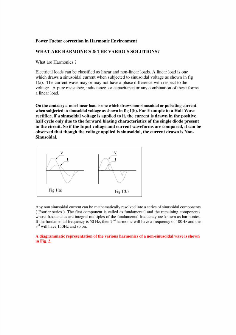
On the contrary a non-linear load is one which draws non-sinusoidal or pulsating current
when subjected to sinusoidal voltage as shown in fig 1(b). For Example in a Half Wave
rectifier, if a sinusoidal voltage is applied to it, the current is drawn in the positivehalf cycle only due to the forward biasing characteristics of the single diode present
in the circuit. So if the Input voltage and current waveforms are compared, it can be
observed that though the voltage applied is sinusoidal, the current drawn is Non-
Sinusoidal.
Fig 1(a) Fig 1(b)
V
I I
V
Any non sinusoidal current can be mathematically resolved into a series of sinusoidal components
( Fourier series ). The first component is called as fundamental and the remaining components
whose frequencies are integral multiples of the fundamental frequency are known as harmonics.
If the fundamental frequency is 50 Hz, then 2nd harmonic will have a frequency of 100Hz and the
3rd will have 150Hz and so on.
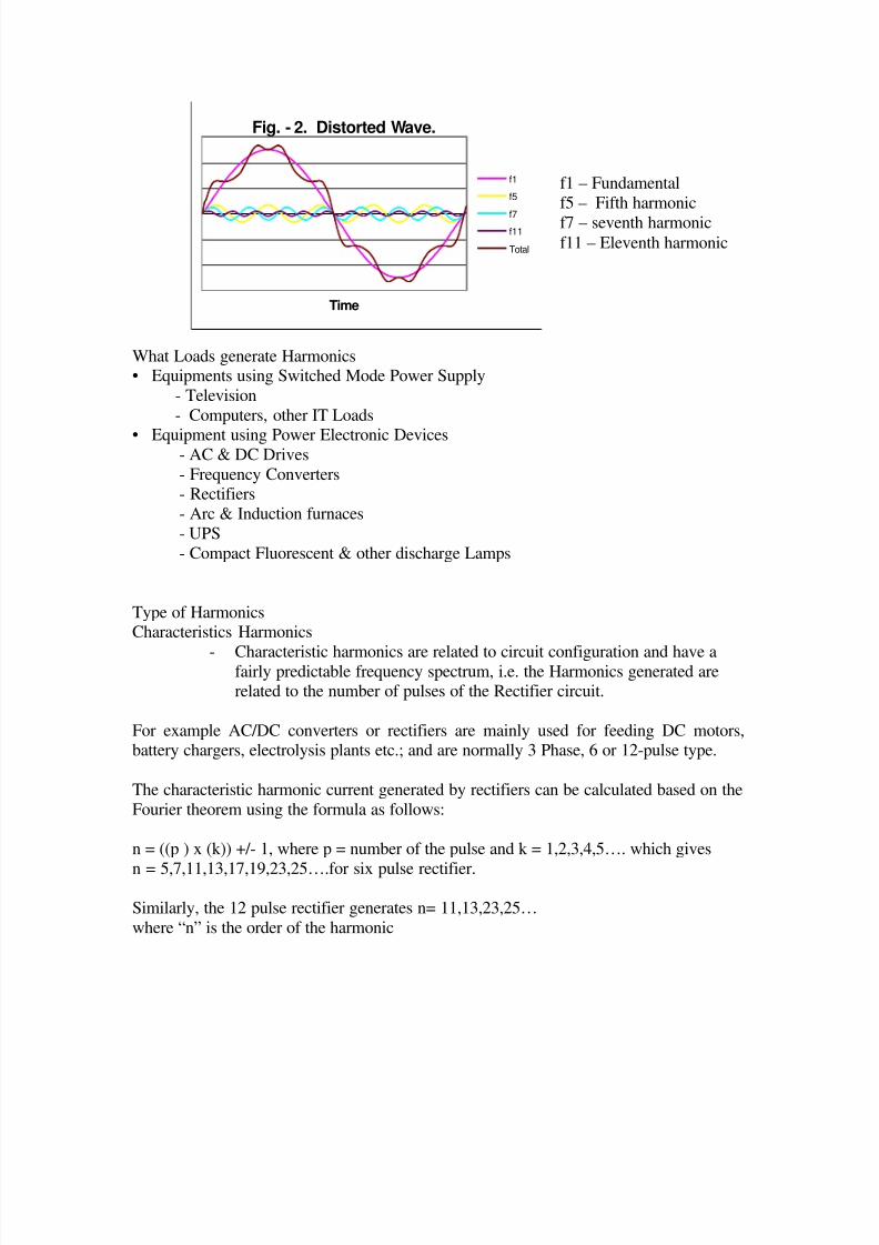
A diagrammatic representation of the various harmonics of a non-sinusoidal wave is shownin Fig. 2.
8/13/2019 Training Paper on Power Factor Correction
http://slidepdf.com/reader/full/training-paper-on-power-factor-correction 16/32
Fig. - 2. Distorted Wave.
Time
f1
f5
f7f11
Total
What Loads generate Harmonics• Equipments using Switched Mode Power Supply
- Television
- Computers, other IT Loads
• Equipment using Power Electronic Devices- AC & DC Drives
- Frequency Converters- Rectifiers
- Arc & Induction furnaces
- UPS
- Compact Fluorescent & other discharge Lamps
Type of HarmonicsCharacteristics Harmonics
- Characteristic harmonics are related to circuit configuration and have afairly predictable frequency spectrum, i.e. the Harmonics generated arerelated to the number of pulses of the Rectifier circuit.
For example AC/DC converters or rectifiers are mainly used for feeding DC motors,battery chargers, electrolysis plants etc.; and are normally 3 Phase, 6 or 12-pulse type.
The characteristic harmonic current generated by rectifiers can be calculated based on the
Fourier theorem using the formula as follows:
n = ((p ) x (k)) +/- 1, where p = number of the pulse and k = 1,2,3,4,5…. which gives
n = 5,7,11,13,17,19,23,25….for six pulse rectifier.
Similarly, the 12 pulse rectifier generates n= 11,13,23,25…
where “n” is the order of the harmonic
f1 – Fundamental
f5 – Fifth harmonic
f7 – seventh harmonicf11 – Eleventh harmonic
8/13/2019 Training Paper on Power Factor Correction
http://slidepdf.com/reader/full/training-paper-on-power-factor-correction 17/32
Magnitude inversely proportional to order:
The rms value of the individual harmonics for an ideal rectifier can be calculated usingthe formula:
In = I1 / n where: I1 = rms value of the fundamental current
n = harmonic order.
For example I5 = I1 /5= 0.2 * I1
Non-characteristic harmonics.Harmonics produced as a result of imbalance in the a.c. power system or
unsymmetrical delay of firing angle of the converter. They are also produced by
other non-linear, time-varying devices, e.g. frequency changers, florescent lamps,arc furnaces, electric welding machines, etc.
Inter-harmonics a sub group of Non-characteristic harmonics are those harmonicfrequencies which are non integral multiples of the fundamental frequency, for e.g., n
= 5.5, i.e., 5.5 x 50 Hz = 275 Hz.
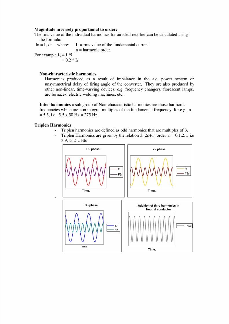
Triplen Harmonics- Triplen harmonics are defined as odd harmonics that are multiples of 3.
- Triplen Harmonics are given by the relation 3.(2n+1) order n = 0,1,2… i.e
3,9,15,21.. Etc
-
R - phase.
Time.
frF3r
Y - phase.
Time.
fyF3y
B - phase.
Time.
fbF3b
Addition of third harmonics in
Neutral conductor
Time.
Total
8/13/2019 Training Paper on Power Factor Correction
http://slidepdf.com/reader/full/training-paper-on-power-factor-correction 18/32
Observe fig above. The 3rd
harmonic current is flowing in all the three phases.
Also these 3rd
harmonic currents are attaining maximum and minimum valuesat the same instant of time, which means that they are in phase with each
other. Hence they get added in the neutral conductor.
Source of Triplen harmonics
One of the best example of the load that generates Triplen harmonic is a computer. Most
of the electronic equipments are single-phase loads and essentially consists of SMPSwhich generate Triplen harmonics.
Effect of Harmonics
• Rotating Machines- Increased losses /over heating due to Skin Effect, PulsatingTorque, reduced efficiency.
• Transformer, Switch-Gear, Power Cables- Increased losses/over heating due to Skin
Effect
• Protective Relays - Maloperation, Nuisance tripping
• Power Electronics- Maloperation, Failure
• Control & Automation- Erratic Operation
• Power Capacitors -High currents & premature failure due to overload
How Capacitors & Harmonics are Related
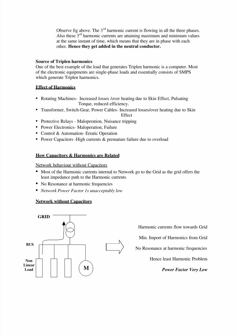
Network behaviour without Capacitors
• Most of the Harmonic currents internal to Network go to the Grid as the grid offers the
least impedance path to the Harmonic currents
• No Resonance at harmonic frequencies
• Network Power Factor 1s unacceptably low
Network without Capacitors
Harmonic currents flow towards Grid
Min. Import of Harmonics from Grid
No Resonance at harmonic frequencies
Hence least Harmonic Problem
Power Factor Very Low M
GRID
BUS
Non
Linear
Load
8/13/2019 Training Paper on Power Factor Correction
http://slidepdf.com/reader/full/training-paper-on-power-factor-correction 19/32
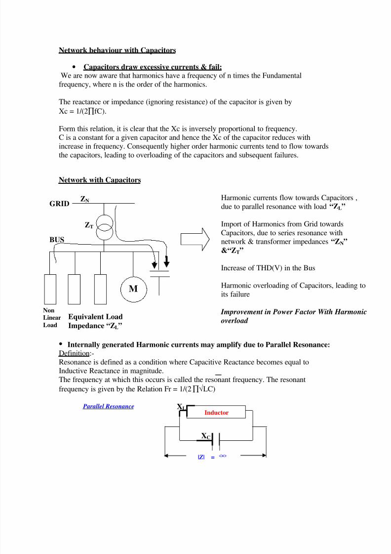
Network behaviour with Capacitors
• Capacitors draw excessive currents & fail:We are now aware that harmonics have a frequency of n times the Fundamental
frequency, where n is the order of the harmonics.
The reactance or impedance (ignoring resistance) of the capacitor is given by
Xc = 1/(2∏fC).
Form this relation, it is clear that the Xc is inversely proportional to frequency.C is a constant for a given capacitor and hence the Xc of the capacitor reduces with
increase in frequency. Consequently higher order harmonic currents tend to flow towards
the capacitors, leading to overloading of the capacitors and subsequent failures.
Network with Capacitors
• Internally generated Harmonic currents may amplify due to Parallel Resonance:Definition:-
Resonance is defined as a condition where Capacitive Reactance becomes equal toInductive Reactance in magnitude.
The frequency at which this occurs is called the resonant frequency. The resonant
frequency is given by the Relation Fr = 1/(2∏√LC)
XL
XC
Harmonic currents flow towards Capacitors ,
due to parallel resonance with load “ZL”
Import of Harmonics from Grid towards
Capacitors, due to series resonance withnetwork & transformer impedances “ZN”
&“ZT”
Increase of THD(V) in the Bus
Harmonic overloading of Capacitors, leading to
its failure
Improvement in Power Factor With Harmonic
overload
Non
Linear
Load
Equivalent Load
Impedance “ZL”
BUS
M
GRID ZN
ZT
Inductor
|Z| =
Parallel Resonance
8/13/2019 Training Paper on Power Factor Correction
http://slidepdf.com/reader/full/training-paper-on-power-factor-correction 20/32
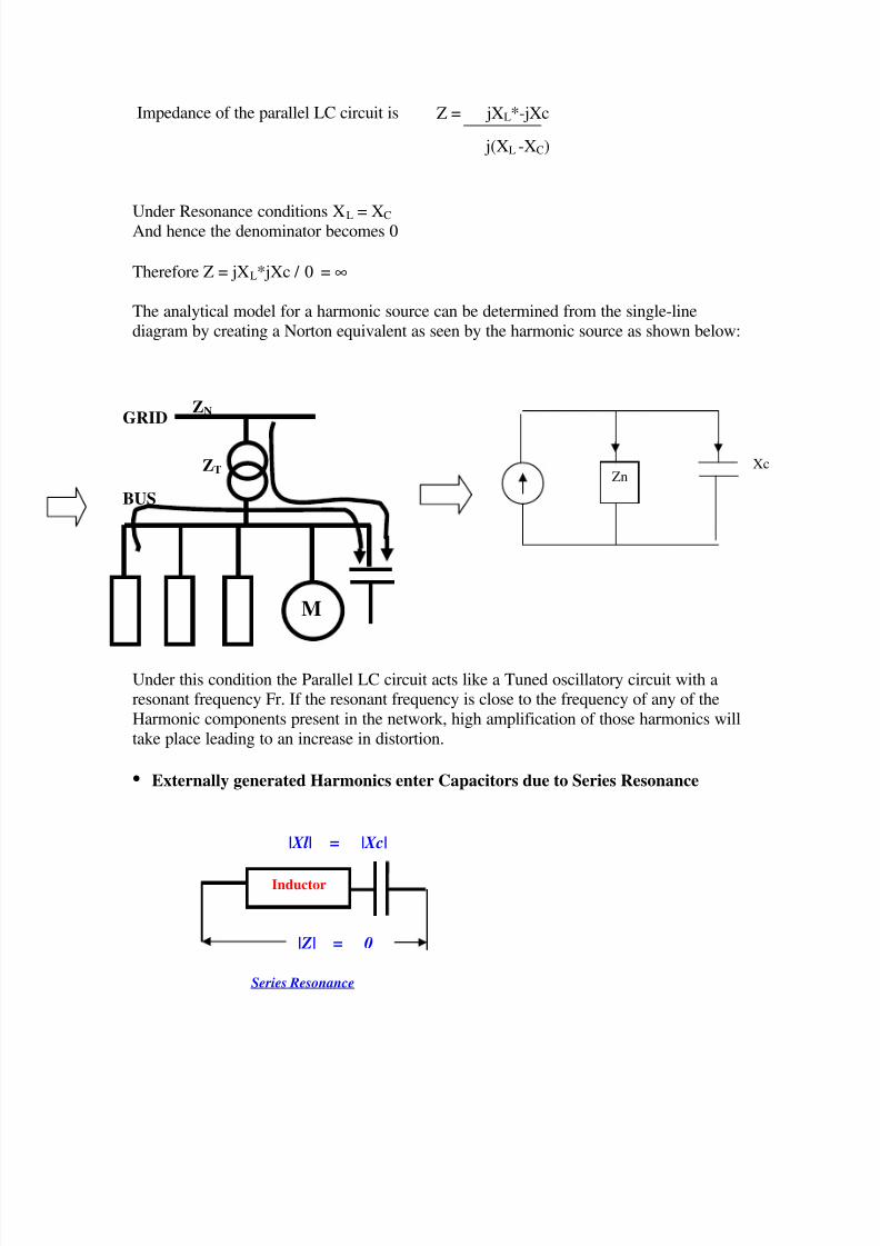
Impedance of the parallel LC circuit is
Under Resonance conditions XL = XC And hence the denominator becomes 0
Therefore Z = jXL*jXc / 0 = ∞
The analytical model for a harmonic source can be determined from the single-line
diagram by creating a Norton equivalent as seen by the harmonic source as shown below:
Under this condition the Parallel LC circuit acts like a Tuned oscillatory circuit with aresonant frequency Fr. If the resonant frequency is close to the frequency of any of the
Harmonic components present in the network, high amplification of those harmonics will
take place leading to an increase in distortion.
• Externally generated Harmonics enter Capacitors due to Series Resonance
Inductor
|Xl| = |Xc|
|Z| = 0
Z = jXL*-jXc
j(XL -XC)
Series Resonance
BUS
M
GRID ZN
ZTZn
Xc
8/13/2019 Training Paper on Power Factor Correction
http://slidepdf.com/reader/full/training-paper-on-power-factor-correction 21/32
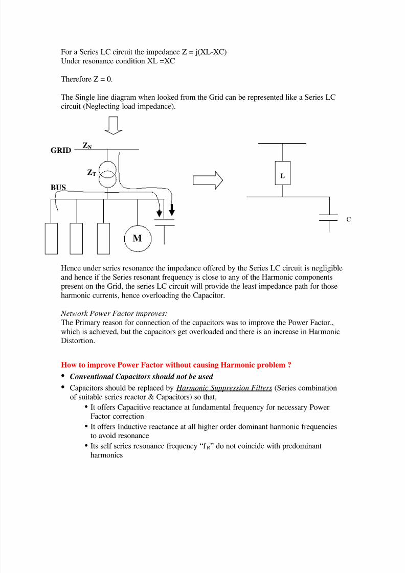
For a Series LC circuit the impedance Z = j(XL-XC)
Under resonance condition XL =XC
Therefore Z = 0.
The Single line diagram when looked from the Grid can be represented like a Series LCcircuit (Neglecting load impedance).
Hence under series resonance the impedance offered by the Series LC circuit is negligibleand hence if the Series resonant frequency is close to any of the Harmonic components
present on the Grid, the series LC circuit will provide the least impedance path for those
harmonic currents, hence overloading the Capacitor.
Network Power Factor improves:
The Primary reason for connection of the capacitors was to improve the Power Factor.,
which is achieved, but the capacitors get overloaded and there is an increase in HarmonicDistortion.
How to improve Power Factor without causing Harmonic problem ?
• Conventional Capacitors should not be used
• Capacitors should be replaced by Harmonic Suppression Filters (Series combinationof suitable series reactor & Capacitors) so that,
• It offers Capacitive reactance at fundamental frequency for necessary PowerFactor correction
• It offers Inductive reactance at all higher order dominant harmonic frequenciesto avoid resonance
• Its self series resonance frequency “f R” do not coincide with predominant
harmonics
BUS
M
GRID ZN
ZT L
C
8/13/2019 Training Paper on Power Factor Correction
http://slidepdf.com/reader/full/training-paper-on-power-factor-correction 22/32
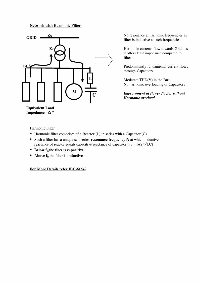
Network with Harmonic Filters
Harmonic Filter
• Harmonic filter comprises of a Reactor (L) in series with a Capacitor (C)
• Such a filter has a unique self series resonance frequency f R at which inductive
reactance of reactor equals capacitive reactance of capacitor. f R = 1/(2π√LC)
• Below f R the filter is capacitive
• Above f R the filter is inductive
For More Details refer IEC-61642
No resonance at harmonic frequencies a
filter is inductive at such frequencies
Harmonic currents flow towards Grid , ait offers least impedance compared tofilter
Predominantly fundamental current flowthrough Capacitors
Moderate THD(V) in the Bus
No harmonic overloading of Capacitors
Improvement in Power Factor without
Harmonic overload
BUS
M
GRID
ZT
Equivalent Load
Impedance “ZL”
ZN
L
C
8/13/2019 Training Paper on Power Factor Correction
http://slidepdf.com/reader/full/training-paper-on-power-factor-correction 23/32
IM
P
E
D
A
NC
E
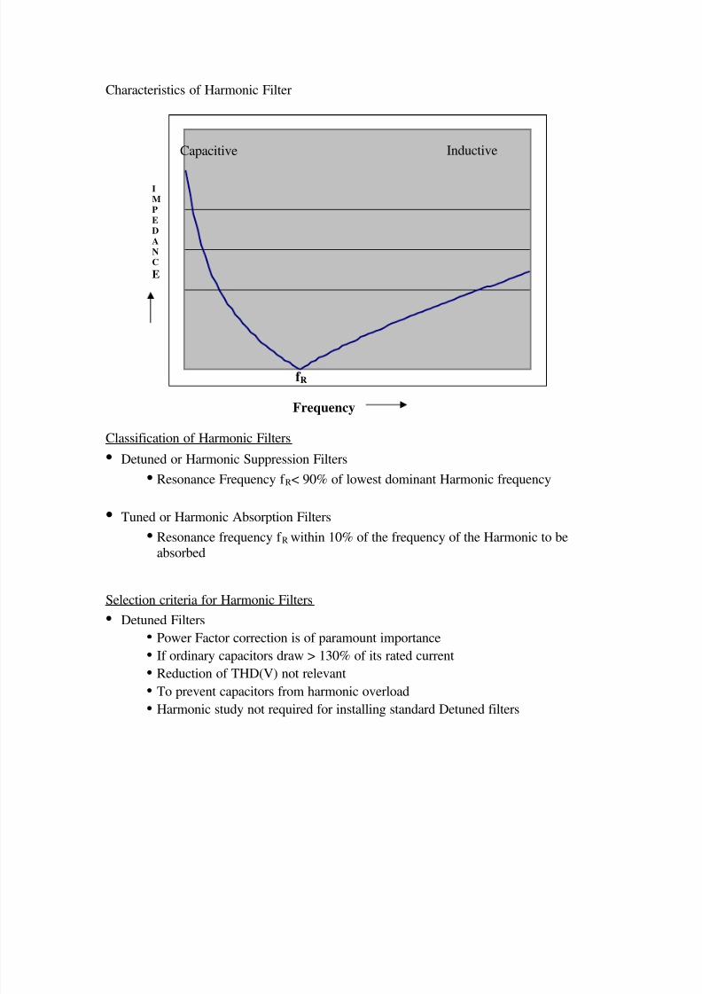
Characteristics of Harmonic Filter
Classification of Harmonic Filters
• Detuned or Harmonic Suppression Filters
• Resonance Frequency f R< 90% of lowest dominant Harmonic frequency
• Tuned or Harmonic Absorption Filters• Resonance frequency f R within 10% of the frequency of the Harmonic to be
absorbed
Selection criteria for Harmonic Filters
• Detuned Filters
• Power Factor correction is of paramount importance
• If ordinary capacitors draw > 130% of its rated current
• Reduction of THD(V) not relevant
• To prevent capacitors from harmonic overload• Harmonic study not required for installing standard Detuned filters
f R
Inductive
Frequency
Capacitive

8/13/2019 Training Paper on Power Factor Correction
http://slidepdf.com/reader/full/training-paper-on-power-factor-correction 24/32
Selection criteria for Harmonic Filters
• Tuned Filters
• Power Factor correction & reduction of THD(V) are of paramount importance
• Ordinary capacitors draw > 130% of its rated current
• Harmonic study required for installing Tuned filters
• Specifically designed for each location
• More bulky, since it carries large amount of harmonic currents. Hence
expensive
From the above it is evident that the introduction of Capacitors in the network opens up a
Pandora’s Box of problems.
Hence at site it is important to run a few checks before recommending a Power factor
solution:
Follow the guidelines given: refer chapter 5 of LT RPM manual.

8/13/2019 Training Paper on Power Factor Correction
http://slidepdf.com/reader/full/training-paper-on-power-factor-correction 25/32
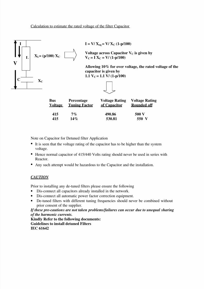
Standard Detuned Filters-1
• Standard detuned filters have a fixed percentage tuning factor “p”
• Percentage tuning factor is defined as
Reactor reactance at system frequencyCapacitor reactance at system frequency
• Standard detuned filters are available for 7 % tuning factor
• The resonant frequency of the filter f R is related to tuning factor “p” by
f R = f S / √√√√(p/100) = 189 Hz for 7% filter
• Standard 7% detuned filters are suitable for use in majority of installations where thedominant harmonics are higher than 189 Hz like 5
th and higher.
• 7% detuned filters should not be used in installations where predominant 3rd
harmonicsare present like “IT based” industries.
• For “IT based” industries 14% detuned filters ( f R=134 Hz) should be used.
Design features of Detuned filter
• Detuned filter consists of matched pair of specially designed Reactor and Capacitor.
• Detuned filter is designed to provide the rated kVAr at the rated voltage at the Bus
• The Reactor Capacitor combination is designed for the rated tuning factor
• Standard Detuned filters are available for 7% tuning factor rated for 12.5, 25, 50, 75 &100 kVAr at 440 Volts.
Design features of Detuned filter
Reactor Features
• Reactors are specially designed to carry wide spectrum of Harmonic and fundamental
currents without saturating.
• They are rated for operation up to 160°C through use of class “F” insulation.
• Over load thermal cut off provided to protect the Reactor
Capacitor Features
• Capacitor is specially designed to carry wide spectrum of Harmonic and fundamentalcurrents without overloading.
• It is designed for higher voltage to allow for increased voltage due to introduction ofseries Reactor
• The kVAr of the capacitor is suitably designed to deliver the rated kVAr of the filter atthe Bus
8/13/2019 Training Paper on Power Factor Correction
http://slidepdf.com/reader/full/training-paper-on-power-factor-correction 26/32
8/13/2019 Training Paper on Power Factor Correction
http://slidepdf.com/reader/full/training-paper-on-power-factor-correction 27/32
CONDUCTING MEASUREMENTS AT SITE:
The following definitions pertaining to Harmonics should be known.
Definitions from IEEE-519 will be inserted
IN the event of the Customer inviting us to conduct a Harmonic study, the following
guidelines have to be followed:
Note these guidelines do not pertain only to conducting a study but also present the actual
situations encountered at site.
1. Before conducting the Study, normally the customer would require a small briefing on
Harmonics, as harmonics is not a widely known subject in the Electrical Field as of
now, and hence their curiosity is justified.In this event a small briefing explaining as to what is Harmonics, their effects on
network and on capacitors can be given. The same has been explained in this paper
and also in the L&T RPM catalogue. This might take up some of your time, but the
Customer will definitely be more accommodating after this briefing. Care should betaken, so as not to go too deep into the subject.
2. Ask for the Single line diagram of the installation. Read the single line diagramcarefully and identify the various points of common coupling. Also identify the if
there are any capacitors and/or Filters (Tuned/Detuned) connected in the
Installation and their locations.
3. Normally the Single line Diagrams are old and some network changes might have
taken place during the course of time. Hence the customer should be asked if
there have been any changes in the network with respect to the single linediagram. If yes, the appropriate changes must be highlighted.
4. All network configurations should be considered including exceptional andemergency arrangements( for e.g. back up sources of supply) as well as possible
future extensions. Special attention should be paid towards electrical machines
(like generators, synchronous compensators), capacitors and Non-Linear Loadsetc.
5. The Fault level of the plant, the Name plate details of the Transformers and
generators, Cable dimensions, length of cables, no. of runs/phase from Power
source to Point of common Coupling should be taken down.
6. Normally the primary objective of the customer is to improve the Power Factor.The electricity bills of the installation will give an idea of the existing power
factor of the installation at the metering point. The tariff structure being followed
by the Electricity board can also be identified from the Bills. The Target powerfactor and hence the kVAr required to achieve the Target power factor can be
arrived at from the bill. (this has been explained in detail earlier)

8/13/2019 Training Paper on Power Factor Correction
http://slidepdf.com/reader/full/training-paper-on-power-factor-correction 28/32
7. In many installations the customer keeps a record of the daily kWh unitsconsumption and the Power Factor at various feeders. A copy of these records for
the past few months will prove very helpful in estimating the type
(Fixed/Variable) and the location of compensation.
8. It is suggested to do a walk around in the Installation . This will help in getting an
complete idea of the Installation, the loads connected, the type of loads, and thelevel of maintenance of the network.
9. After doing the above preliminary checks, request the customer to show thelocation of the Points of common coupling identified by you and proceed with the
measurements.
Preferably measurements should also be carried out at all MCC (motor control
cabinets) and any Major Non-Linear Loads.
10. The instruments available with Meher at present are the
• Fluke 41 B Harmonic Analyzer
• MTE EZ 901 Harmonic Analyzer
• Ducati Harmonic AnalyzerPractical sessions of handling the Fluke 41B and the MTE will be conducted.
11. The Manuals provided along with these instruments also give detailed instructions
on carrying out the measurements and the functionality of the Instrument.
10. The measurements should be carried out with and without the capacitors.
With above instruments Single phase readings will have to be taken. You mightexperience the following difficulties while taking measurements.
• Negative Power readings: The clamp ON CT might be connected in reverse. Inversethe clamp On CT and continue with the measurement.
• The Power factor is abnormally low or leading: The current and voltage
measurements might be in two different phases. For example the CT might beconnected in R phase and the Voltage measurement will be between Y phase and
neutral. This can sometimes lead to erroneous readings. Check the phases and correct.
• No neutral available: In the event of No neutral being available, the body earth can betaken as reference in place of the neutral
• HT measurements:
11. What to deduce from the measurements:Note down the CT and PT ratios if the measurements are being carried at the
secondary of the CT and PT. Check the current recorded by the instrument. Multiply
with CT ratio (if applicable). Check if it matches the optimum load currents at thatpoint.
8/13/2019 Training Paper on Power Factor Correction
http://slidepdf.com/reader/full/training-paper-on-power-factor-correction 29/32
Check the voltage, see if it matches with the specified system voltage.
Check the THDV% recorded by the instrument, check if it is within limits.Check the harmonic current spectrum and identify the Harmonic currents which have
been amplified.
Download the readings on to the computer.
An indication of the values measured can be given to the customer.
The recommended limits for Voltage and current Distortions as per IEEE-519 will be
inserted.
Important formulae
Formula SymbolsC Capacitance (farads)
f Frequency (Hertz)
I Current (amps)Ih = rms current (amps) at harmonic (h)
KVAr =Reactive Power (kvar)
kVAtx = three-phase transformer rating, Ztx = nameplate impedance (%)kVAr = three-phase capacitor bank rating
KVA =Total Power (kVA)
kV =kilovolts (kV)KW =Real Power (kW)
PF =Power Factor (no unit)
P Real Power (KW)
Q Reactive Power (kVAr)
S Total Power (KVA)Subscript I Initial
Subscript d DesiredSubscript Three Phase
Subscript Single Phase
Subscript LN Line to NeutralSubscript LL Line to Line
Subscript SC Short Circuit
Th = single frequency TIF at harmonic (h)
Vn = harmonic voltage magnitudeVrms, Irms = Root mean square (rms) value of voltage and current
Vpk = peak magnitudeXc Capacitive Reactance (ohms)
Xc = capacitive reactance (Ω), XL = inductive reactance (Ω), R = resistance (Ω)
Xn = filter inductor - reactance (Ω), n = harmonic at which filter is tuned
θ = power factor angle
8/13/2019 Training Paper on Power Factor Correction
http://slidepdf.com/reader/full/training-paper-on-power-factor-correction 30/32
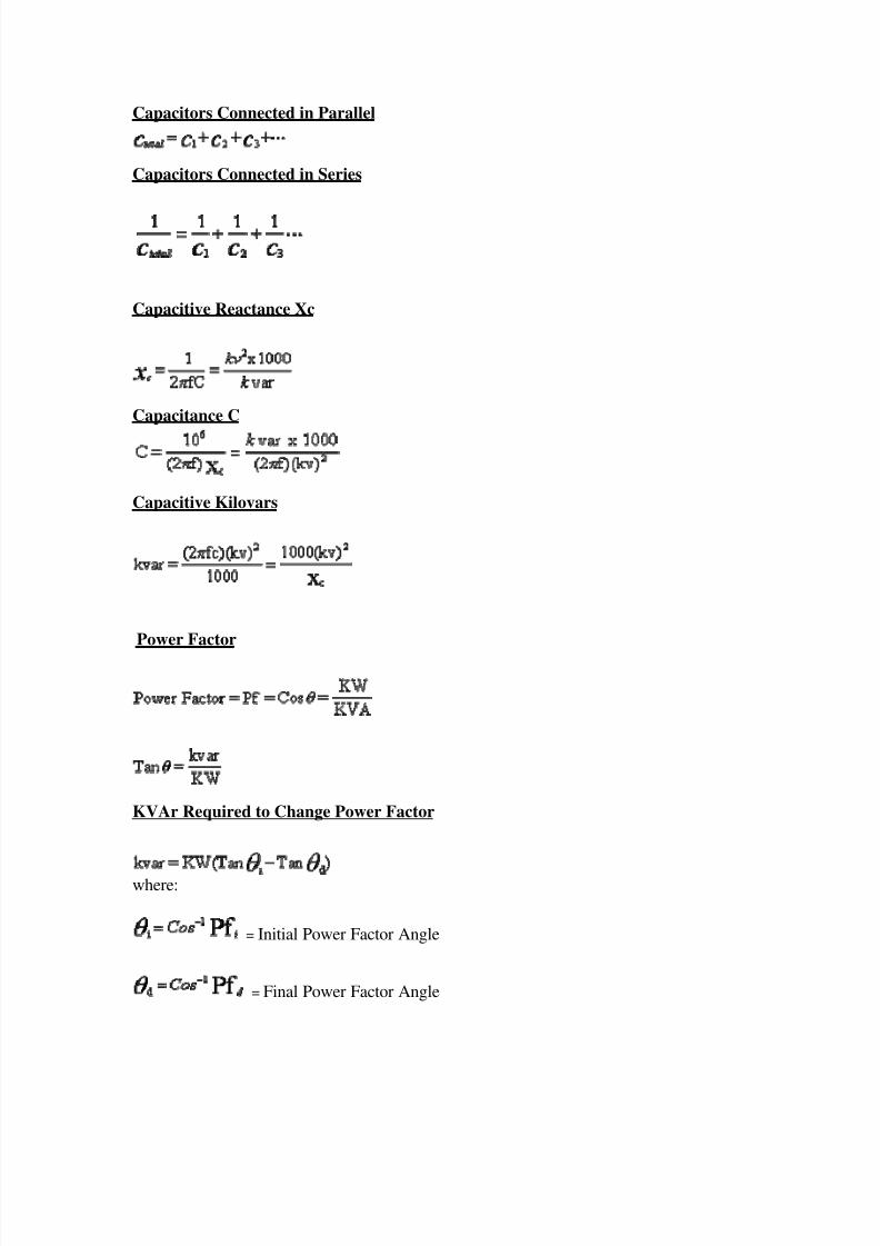
Capacitors Connected in Parallel
Capacitors Connected in Series
Capacitive Reactance Xc
Capacitance C
Capacitive Kilovars
Power Factor
KVAr Required to Change Power Factor
where:
= Initial Power Factor Angle
= Final Power Factor Angle
8/13/2019 Training Paper on Power Factor Correction
http://slidepdf.com/reader/full/training-paper-on-power-factor-correction 31/32
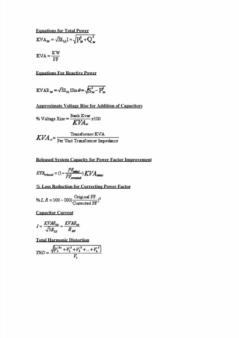
Equations for Total Power
Equations For Reactive Power
Approximate Voltage Rise for Addition of Capacitors
Released System Capacity for Power Factor Improvement
% Loss Reduction for Correcting Power Factor
Capacitor Current
Total Harmonic Distortion
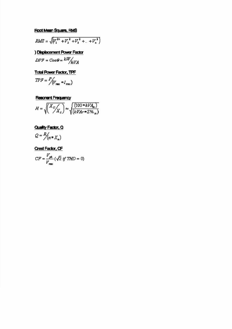
8/13/2019 Training Paper on Power Factor Correction
http://slidepdf.com/reader/full/training-paper-on-power-factor-correction 32/32