training process manual for wtp narmada
TRANSCRIPT

sustainable solutions. for a better life.
VA TECH WABAG
Page 1
P097-T0002-001
TRAINING PROGRAMME
WATER TREATMENT PLANTFOR
PHED, BHOPAL
sustainable solutions. for a better life.
VA TECH WABAG
Page 2
P097-T0002-001
195 MLD Water Treatment PlantFor
Public Health Engineering Department, Bhopal
Training Boucher Water Treatment Plant
Section I - ProcessSection II - MechanicalSection III - Electrical & Instrumentation

sustainable solutions. for a better life.
VA TECH WABAG
Page 3
P097-T0002-001
INTRODUCTION
M/S Public Health Engineering Department has entrusted M/S. VA Tech Wabag Ltd.(JV) for the execution of 195 MLD Water Treatment Plant of normal works output at Khatpura Village (Shahganj), Seshore (Dt), Bhopal, supplies drinking water to Bhopal.
The WTP receives raw water from the river Narmada at village Hirani on Shahganj-Budni Road, pumped through 1400 mm dia MS pipe.
The WTP is based on the Clariflocculator Technology for clarification followed by filtration in Rapid Gravity Sand Filters.
The scope also includes disinfection of filtered water for making it suitable for drinking purposes at WTP site Khatpura and chlorine boosting arrangement at clear water sump at Ahmedpur, Bhopal.
sustainable solutions. for a better life.
VA TECH WABAG
Page 4
P097-T0002-001
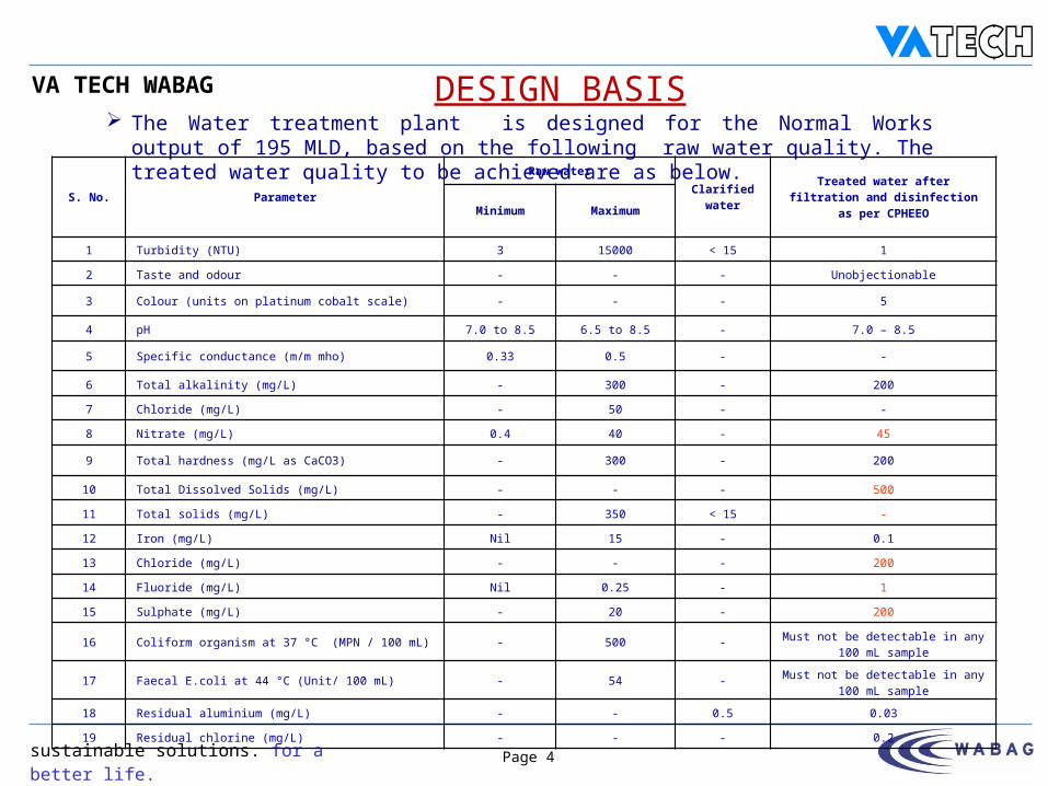
DESIGN BASIS The Water treatment plant is designed for the Normal Works output of 195 MLD, based
on the following raw water quality. The treated water quality to be achieved are as below.
S. No. ParameterRaw water
Clarified water
Treated water after filtration and disinfection as per CPHEEOMinimum Maximum
1 Turbidity (NTU) 3 15000 < 15 1
2 Taste and odour - - - Unobjectionable
3 Colour (units on platinum cobalt scale) - - - 5
4 pH 7.0 to 8.5 6.5 to 8.5 - 7.0 – 8.5
5 Specific conductance (m/m mho) 0.33 0.5 - -
6 Total alkalinity (mg/L) - 300 - 200
7 Chloride (mg/L) - 50 - -
8 Nitrate (mg/L) 0.4 40 - 45
9 Total hardness (mg/L as CaCO3) - 300 - 200
10 Total Dissolved Solids (mg/L) - - - 500
11 Total solids (mg/L) - 350 < 15 -
12 Iron (mg/L) Nil 15 - 0.1
13 Chloride (mg/L) - - - 200
14 Fluoride (mg/L) Nil 0.25 - 1
15 Sulphate (mg/L) - 20 - 200
16 Coliform organism at 37 °C (MPN / 100 mL) - 500 - Must not be detectable in any 100 mL sample
17 Faecal E.coli at 44 °C (Unit/ 100 mL) - 54 - Must not be detectable in any 100 mL sample
18 Residual aluminium (mg/L) - - 0.5 0.03
19 Residual chlorine (mg/L) - - - 0.2

sustainable solutions. for a better life.
VA TECH WABAG
Page 5
P097-T0002-001
SECTION – 1 A
Water Treatment Philosophy
sustainable solutions. for a better life.
VA TECH WABAG
Page 6
P097-T0002-001
WATER TREATMENT PHILOSOPHY The raw water in this scheme undergo the following treatment
steps so that it can be used for the purpose of drinking water.
1) Aeration
2) Pre-chlorination
3) Alum and Lime dosing
4) Flocculation
5) Clarification
6) Filtration
7) Post-chlorination
sustainable solutions. for a better life.
VA TECH WABAG
Page 7
P097-T0002-001
AERATION The primary objectives of aeration of raw water are, to expel dissolved gases such as Carbon Dioxide and volatile substances
that cause taste and odour. to increase Dissolved Oxygen of raw water. to precipitate Iron and Manganese from their soluble form to insoluble
form.
CHLORINATIONThe primary objectives of the pre chlorination of raw water are: to control the growth of algae and other microorganisms that might
interfere with coagulation and flocculation and to reduce the coagulant dose.
keeping filter media free of slime growths and mud balls which not only impair the filtration efficiency but also interfere with proper backwashing.
The post chlorination of filtered water ensures disinfection of filtered water to make it suitable for human consumption as drinking water, killing all the germs present in the filtered water.
sustainable solutions. for a better life.
VA TECH WABAG
Page 8
P097-T0002-001
CHLORINATION (Contd.)Chlorine is used Due to its oxidizing effect on organic matter and Its germicidal effect in killing germs and viruses. Chlorine gas when dissolved in water, hydrolyzes rapidly :
Cl2 + H2O H+ + Cl - + HOCl
The weak hypochlorous acid (HOCl) undergoes partial dissociation:
HOCl H+ + OCl -

sustainable solutions. for a better life.
VA TECH WABAG
Page 9
P097-T0002-001
CHLORINATION (Contd.)
At 7.5 pH, the undissociated hypochlorous acid (HOCl) and the hypochlorite ion (OCl -) is 50:50. The lower the pH values, the amount of HOCl becomes proportionately higher which has germicidal efficiency better than the OCl – ions.
The raw water supply is from Narmada river and its pH range is 6.5 to 8.5 and the pH of raw water is mostly expected to be around 7.0 which is conducive for the predominant presence of HOCl ions which in turn ensure effective chlorination.

sustainable solutions. for a better life.
VA TECH WABAG
Page 10
P097-T0002-001
FLASH MIXING
Turbidity is caused by fine suspended solids, colloids and color. The particles are negatively charged. The particles remain in stable suspension by the action of electrostatic forces
of repulsion. Dose Alum (coagulant) and Lime (adding alkalinity) to neutralized the
charges. Ensures uniform dispersion of the chemical by rapid mixing in Flash Mixer.
Ensure the flocs formation. Ascertain the optimum dosage of coagulant by Jar Test, under optimum pH
zone. Lime is dosed to bring about optimum pH zone. Alum is used as the coagulant chemical and dosed at the inlet channel of
Flash Mixer.
sustainable solutions. for a better life.
VA TECH WABAG
Page 11
P097-T0002-001
A typical reaction of alum may be expressed as :
Al2 (SO4)3.18 H2O → 2 Al 3+ + 3 SO4 - + 18 H2O
2 Al 3+ + 6 OH- → Al2O3. 3 H2O
Hydroxyl ions must be supplied by alkalinity either natural or added for the aluminium oxide to hydrate. The required alkalinity is supplied by addition of Lime.
Ca (OH)2 → Ca + 2 OH-
pH of water plays a very important part in the coagulation phenomenon. The required alum and lime dosage, as determined by Jar Test, to be maintained to ensure good coagulation.
The mixing of the chemicals with raw water is provided in the Flash Mixer. This helps in the formation of microflocs.
FLASH MIXER (Contd.)
sustainable solutions. for a better life.
VA TECH WABAG
Page 12
P097-T0002-001
CLARIFLOCCULATIONWhat is clariflocculation?
Clariflocculation means “ SEDIMENTATION WITH FLOCCULATION IN A SINGLE UNIT”.
Unit comprises of two circular concentric tanks viz. inner tank where flocculation is happening and outer tank where settling is happening.
Principle of clariflocculation
The particles do not keep their individuality, but tend to agglomerate helped by some coagulants. The sludge floc size increases and, as a consequence, the sedimentation speed increases too.
A retention time of 30 minutes is provided for flocculation along with gentle and prolonged mixing also.

sustainable solutions. for a better life.
VA TECH WABAG
Page 13
P097-T0002-001
CLARIFLOCCLATION (contd.)
Optimum dosage requirement of Alum / Lime for flocculation is determined by the Jar Test, as a daily routine.
The most significant design aspect is the available settling area, since the throughput (m3/h) divided by the tank area (m2) must not exceed the settling velocity of the slowest settling particle to be separated – usually to 1 to 2 m/h
The efficiency depends on the Surface Overflow Rate (SOR). It is independent of depth.
SOR = flow rate through the clarifier divided by the settling area = Q / A
sustainable solutions. for a better life.
VA TECH WABAG
Page 14
P097-T0002-001
CLARIFLOCCLATION (contd.)Stages of clariflocculation
A complete process of clariflocculation mainly consists of three subsequent stages:
• Mixing of the inflow (raw water) with the reagents (Alum and lime)• Flocculation• Sedimentation
The raw water mixing with the reagents must be made very quickly and with a strong stirring. On the contrary, the flocculation must be slow in order to allow the flocs agglomeration and any turbulent motion must be avoided.
The clarified water is then collected in the upper part through circular or radial launders and the sludge on the tank bottom is conveyed into a sludge sump by some scrapers.
sustainable solutions. for a better life.
VA TECH WABAG
Page 15
P097-T0002-001
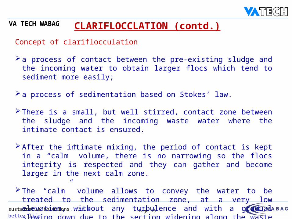
CLARIFLOCCLATION (contd.)Concept of clariflocculation
a process of contact between the pre-existing sludge and the incoming water to obtain larger flocs which tend to sediment more easily;
a process of sedimentation based on Stokes’ law.
There is a small, but well stirred, contact zone between the sludge and the incoming waste water where the intimate contact is ensured.
After the intimate mixing, the period of contact is kept in a “calm” volume, there is no narrowing so the flocs integrity is respected and they can gather and become larger in the next calm zone.
The “calm” volume allows to convey the water to be treated to the sedimentation zone, at a very low elevation, without any turbulence and with a gradual slowing down due to the section widening along the waste water flowing upwards.
sustainable solutions. for a better life.
VA TECH WABAG
Page 16
P097-T0002-001
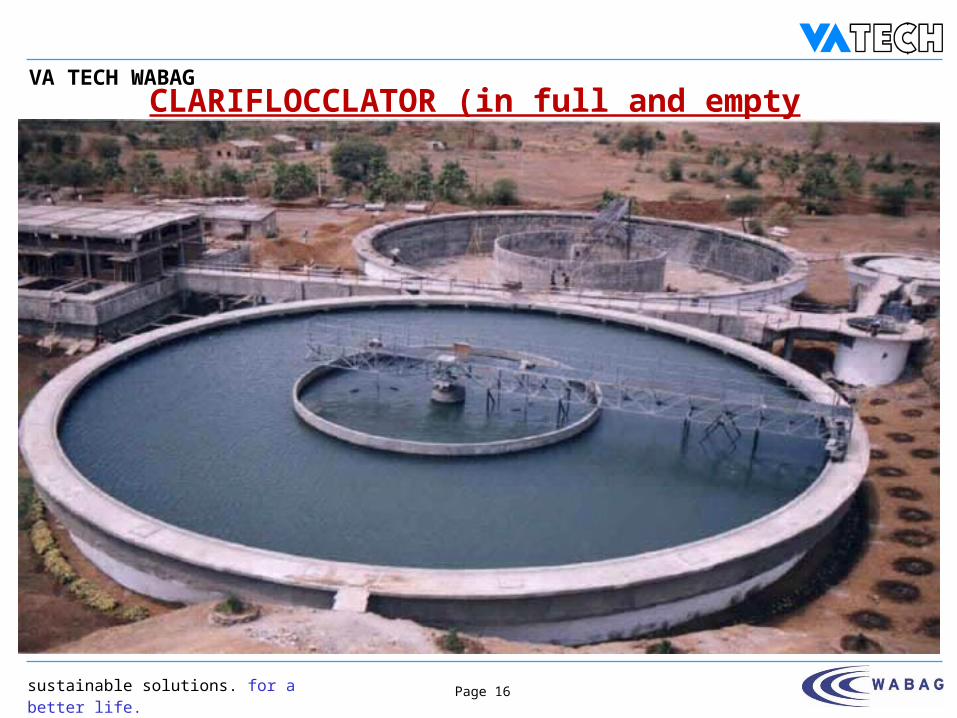
CLARIFLOCCLATOR (in full and empty condition)
sustainable solutions. for a better life.
VA TECH WABAG
Page 17
P097-T0002-001
MAJOR FACTORS AFFECTING THE PERFORMANCE OF CLARIFLOCCULATOR
Expected quality of clarified water is 15 NTU
However the performance may be impaired due to:
Right dosage of coagulant / lime, as per Jar Test, is not dosed.
Formation of larger flocs in flocculation tank is not properly achieved.
Sludge withdrawal programme not properly operated, resulting in sludge buildup.
sustainable solutions. for a better life.
VA TECH WABAG
Page 18
P097-T0002-001
FILTRATION
Filtration is a process for separating suspended and colloidal impurities, held in suspension, from water through a porous medium or media.
Removal of turbidity is essential not only for aesthetic acceptability but also for efficient disinfection which is difficult in the presence of suspended solids and colloidal impurities.
Filters can be classified according to
(1) the direction of flow
(2) types of filter media and beds
(3) the driving force
(4) the method of flow rate control The Filters adopted for the project are of down flow, granular mono media, rapid
gravity filters operating at declining rate.
sustainable solutions. for a better life.
VA TECH WABAG
Page 19
P097-T0002-001
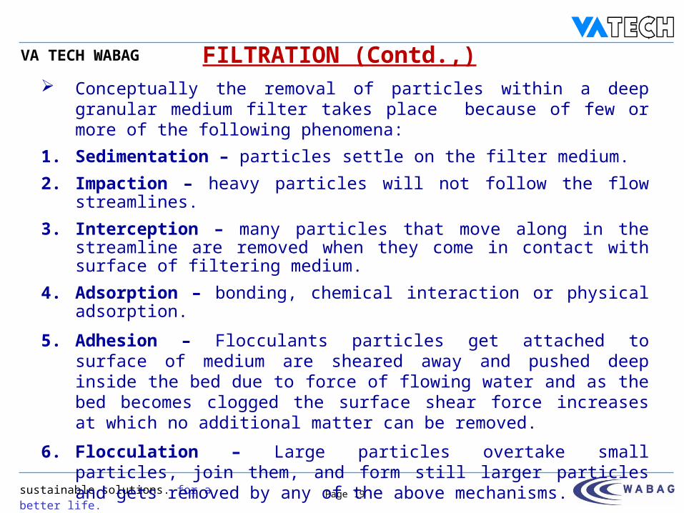
Conceptually the removal of particles within a deep granular medium filter takes place because of few or more of the following phenomena:
1. Sedimentation – particles settle on the filter medium.2. Impaction – heavy particles will not follow the flow streamlines.3. Interception – many particles that move along in the streamline are
removed when they come in contact with surface of filtering medium.4. Adsorption – bonding, chemical interaction or physical adsorption.
5. Adhesion – Flocculants particles get attached to surface of medium are sheared away and pushed deep inside the bed due to force of flowing water and as the bed becomes clogged the surface shear force increases at which no additional matter can be removed.
6. Flocculation – Large particles overtake small particles, join them, and form still larger particles and gets removed by any of the above mechanisms.
7. Biological growth – Biological growth within the filter reduces the pore volume and may enhance the removal mechanism by any of the above mechanisms.
FILTRATION (Contd.,)
sustainable solutions. for a better life.
VA TECH WABAG
Page 20
P097-T0002-001
FILTRATION (Contd.,)
Each filter bed is provided with state-of-the-art underdrain system, incorporating ‘sand tight’ polypropylene nozzles fixed on a monolithic reinforced concrete false floor at 60 nos. per m²
The system ensures
- uniform draw-off of filtered water & its efficient collection and
- efficient control of the uniform distribution of air and wash water, over the whole area of the filter, during filter cleaning.
The filters shall be cleaned on a 24 hour cycle or when the filter bed is clogged up to the admissible filter loss.
sustainable solutions. for a better life.
VA TECH WABAG
Page 21
P097-T0002-001
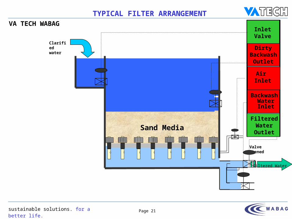
Sand Media
TYPICAL FILTER ARRANGEMENT
Clarified water
Valve Opened
Inlet Valve
Filtered Water Outlet
Air Inlet
Backwash WaterInlet
Dirty Backwash
Outlet
Filtered Water

sustainable solutions. for a better life.
VA TECH WABAG
Page 22
P097-T0002-001
SECTION – 1 B
Process Units
sustainable solutions. for a better life.
VA TECH WABAG
Page 23
P097-T0002-001
PROCESS UNITS WTP consists of the following process units:
Cascade Aerator Primary Sedimentation Tank Flash Mixer Clariflocculator Rapid Gravity Filters Overhead Backwash Water Tank Dirty Backwash Water Collection Tank Clear Water Sump Sludge Sump Sludge Drying Bed Alum Solution Preparation and Dosing System Lime Solution Preparation and Dosing system Chlorine Dosing Facilities
sustainable solutions. for a better life.
VA TECH WABAG
Page 24
P097-T0002-001
CASCADE AERATOR Raw water is received through a 1400 mm dia. pumping main into the Cascade
Aerator inlet. A manual butterfly valve is provided on the inlet line for isolation purpose. The raw water is aerated in the Aerator, by allowing raw water to fall over three circular steps.
One no. Parshall Flume with ultrasonic transmitter is provided at the outlet of Cascade Aerator / Primary Sedimentation Tank for monitoring the raw water flow. Local cum remote indication for the same is provided with cumulative flow totaliser.
Chlorine is dosed at 2 ppm at the outlet channel through a diffuser. The pre-chlorinated raw water is conveyed through the Aerator outlet channel to
the Primary Sedimentation Tank followed by Flash Mixer or directly to Flash Mixer or bypassing the entire system and fed into the Rapid Gravity Sand Filters depends on the turbidity of Raw water / any maintenance.
pH analyzer, turbidity analyzer and DO analyzer are provided at the inlet of the pipeline to determine the raw water characteristics.
Also raw water samples are drawn from the Aerator inlet for routine monitoring of pH, turbidity and DO.

sustainable solutions. for a better life.
VA TECH WABAG
Page 25
P097-T0002-001
PRIMARY SEDIMENTATION TANK
2 nos. Primary Sedimentation Tanks are provided after cascade aerator. Manual gates are provided to isolate the primary sedimentation tanks in case of
maintenance. Manual gate is provided in the main channel to bypass both the primary
sedimentation tanks. The primary sedimentation tanks are peripheral type of clarifiers 58.8 m
diameter used for suspended solids removal and is designed for the retention time of 3 h.
Settled sludge is withdrawn from the sedimentation tanks through respective sludge withdrawal lines.
Gate valves are provided for isolation of the sludge lines. Flushing connections are provided on these lines for maintenance purpose.
Additionally drain of sludge to plant overall drain facility is provided to bypass the entire sludge to Nalla during high turbidity inflows.
sustainable solutions. for a better life.
VA TECH WABAG
Page 26
P097-T0002-001
FLASH MIXER
The raw water after flow measurement by Parshall Flume is received in a Flash Mixer designed for the retention time of 0.75 min at a design flow of 8478 m³/hr.
Alum and lime solution are dosed into the raw water at the upstream of Parshall flume and entering into the Flash Mixer.
The Flash Mixer is constructed in RCC and is equipped with agitators for intimate mixing of raw water with chemicals.
Dirty wash water from the Dirty Wash Water collection Tank is recycled into the Flash Mixer.
Each of the Flash Mixers can be isolated by gates. A bypass gate is provided in the main channel from Parshall flume to bypass
the Flash Mixers and Clariflocculators and feed raw water directly into the filters.Butterfly valves are provided for draining the Flash Mixer during maintenance.
sustainable solutions. for a better life.
VA TECH WABAG
Page 27
P097-T0002-001
Raw water from the flash mixers is conveyed to Clariflocculators through a distribution chamber with isolation gates for each of the clariflocculator.
4 nos. Clariflocculators constructed in RCC are provided with a flocculation chamber and clarifier with a design capacity of 195 MLD.
Size of each Clariflocculator 43.9 m dia x 3.5 m LD and each Clariflocculator is capable of handling the flow of 48.75 MLD.
The retention time of 30 min is provided in the flocculator zone and 2 h is provided in the clarifier zone.
Each of the unit is equipped with 4 nos. flocculator mechanisms in the flocculator zone and a peripherally driven sludge raking mechanism in the clarifier zone. The clarified water is passed through the submerged orifices provided on the peripheral double weir launders of the Clariflocculator.
The clarified water from Clariflocculators is conveyed by gravity to the inlet channel of the Rapid Gravity Filters.
CLARIFLOCCULATOR

sustainable solutions. for a better life.
VA TECH WABAG
Page 28
P097-T0002-001
The sludge from the Clariflocculator is withdrawn through a telescopic sludge bleeding arrangement.
Isolation valves are provided on the main sludge withdrawal line of the clarriflocculators.
Drain valves are provided to drain the sludge into the plant overall drainage system routed to Nalla. Flushing connections are provided on the sludge line for routine maintenance.
Sampling point with isolation gate valve is provided to collect the sample of the clarified water.
The Clariflocculator is designed for 2780 mg/L of SS.
CLARIFLOCCULATOR (contd.)
sustainable solutions. for a better life.
VA TECH WABAG
Page 29
P097-T0002-001
Water enters at the bottom of the central pier of the Clariflocculator and flows through the openings in the central pier into the Flocculation zone.
After entering the Flocculation zone, the water flows into the clarifier zone. The incoming solids get distributed whereby the flocs can enter the clarifier zone in the outer portion and the clarified water overflow takes place over the weirs.
Clarified water is directed to the overflow launders, which lead clarified water to Rapid Gravity Filters and to Clear Water sump based on the turbidity. Sampling point is provided in the common outlet channel of clariflocculator.
The sludge settling on the floor of the Clariflocculators will be scrapped by mechanical scrapper, to the central pit.
The sludge from each clarifier is discharged to the Sludge Sump, intermittently.
A torque switch will trip the scraper mechanism due to high torque, when there is overload or if there is any obstacle for the scraper to move.
CLARIFLOCCULATOR (contd.)
sustainable solutions. for a better life.
VA TECH WABAG
Page 30
P097-T0002-001
The desludging operation of Clariflocculator is designed for discharging the sludge by intermittent bleed.
The intermittent desludging operation helps in increasing the consistency of sludge, which minimises the water losses.
The desludging control has been programmed for desludging the clarifiers, every hour. The cycle starts from Clariflocculator-1 and proceeds to other and the cycle restarts again. The duration of desludging of each clarifier depends on the incoming raw water turbidity load.
The sludge from each Clariflocculator is discharged through the sludge withdrawal pipe to the Sludge Sump.
A drain connection is also provided in the sludge withdrawal line for draining the Clariflocculator.
Flushing water connections are provided to facilitate flushing of sludge pipes, in the event of blockages / also to prevent blockages.
DESLUDGING OF CLARIFLOCCULATOR
sustainable solutions. for a better life.
VA TECH WABAG
Page 31
P097-T0002-001
Ensure the overflow weir plates are properly leveled. Seal the gaps in between the weir plates and launders.
Keep the outlet gate leading to the Clear Water sump, drain valves and sludge drain valves closed.
Ensure the oil level in the gear reducer / drive unit of scraper mechanism is o.k.
Keep the torque switch in working condition. Switch on scrapper bridge mechanism. Open the outlet gate of the Flash Mixer and receive the coagulated water
through the central pier. Keep the flocculator paddles running at the optimum speed, to ensure
good flocculation.The flocculated raw water enters Lamella Clarifier under its overflow
channels and flows upwards , in between the inclined parallel plates.
CLARIFLOCCULATOR – START UP
sustainable solutions. for a better life.
VA TECH WABAG
Page 32
P097-T0002-001
Check the torque indicator for any overload due to obstruction of the scraper mechanism and check the smooth rotation of the scraper mechanism.
Desludge the clariflocculator once sludge is more. (Actual cycles and duration of sludge bleed depends on the actual raw water suspended solids, turbidity and raw water flow).
Defer the de-sludging if the sludge level in the sludge sump is high.
Flush the individual sludge line by opening the flushing valves provided (once a week).
Collect-clarified water through the sampling valve (GV-217) provided in the clarified water channel and ensure the quality conforms to desired quality. In case of high turbidity of clarified water, check for correct chemical dosing rate and sludge bleed. Also ensure all flocculators and scraper mechanisms are running.
CLARIFLOCCULATOR – START UP (Contd.)
sustainable solutions. for a better life.
VA TECH WABAG
Page 33
P097-T0002-001
Look out for any algal growth on the weir surface and tank walls. If growth is observed, ensure residual chlorine at clarifier outlet is at least 0.5 to 0.6 mg/L.
Adjust the dosage rate of the alum / lime solution , if required, to ensure the turbidity of clarified water is within the design values.
Reschedule the sludge withdrawal programme, as required, in case of wide changes in the raw water turbidity and raw water flow.
In case of trip of scrapper due to high torque, do not attempt to restart the scrapper mechanism without proper investigation.
CLARIFLOCCULATOR – START UP (Contd.)
sustainable solutions. for a better life.
VA TECH WABAG
Page 34
P097-T0002-001
SHUT DOWN FOR MAINTENANCE Close the outlet gate of the Flash Mixer which fed the coagulated water
to the clarifloculator to be isolated and drain the sludge by opening its sludge valves. Keep the paddles and scraper mechanism running.
Defer the desludging of other Clariflocculator till the emptying is completed.
Allow the sludge into the sludge sump.Stop the paddles and scraper mechanism at local or at MCC when the
water level is lowered exposing them. Isolate the unit and the power supply for the equipment at MCC and
handover for maintenance.
CLARIFLOCCULATOR – SHUT DOWN
sustainable solutions. for a better life.
VA TECH WABAG
Page 35
P097-T0002-001
PARTIAL SHUT DOWN WITHOUT MAINTENANCE In case of partial shut down for the reduced inflow, isolate the
Clariflocculator which is not required, by closing the outlet gates of the corresponding Flash Mixer.
Reduce the dosing rate of chlorine, lime and alum proportionate to the requirement of turn down capacity.
Before isolating, it shall be ensured that the accumulated sludge in the clariflocculator, to be isolated, shall be desludged.
It is preferable to keep the paddle and scraper mechanism running.
CLARIFLOCCULATOR – SHUT DOWN (CONTD.)

sustainable solutions. for a better life.
VA TECH WABAG
Page 36
P097-T0002-001
COMPLETE SHUT DOWN Inform the raw water pumping station in-charge to stop pumping
water to the Water Treatment Plant, if it is decided to go in for complete shut down of the plant.
Ensure that sludge in the Clariflocculators shall be fully drained out. Ensure all the sludge lines are properly flushed clean, the units and
the equipment shall be stopped / isolated. Stop the running equipment at local. Isolate the power supply for the equipment at MCC, if it is to be taken
up for maintenance. Isolate all the chemical dosing system.
CLARIFLOCCULATOR – SHUT DOWN (CONTD.)

sustainable solutions. for a better life.
VA TECH WABAG
Page 37
P097-T0002-001
As a matter of routine, a Clariflocculator can be isolated for cleaning of overflow launders, once a week, deteriorating the quality of clarified water.
Before isolating the Clariflocculator that is to be cleaned, ensure the other Clariflocculator and its connected Flash Mixer are in service.
Then isolate the Clarifier selected for cleaning by closing the corresponding outlet gate of Flash Mixer.
Keep the paddles and scraper mechanism running.Schedule the cleaning programme preferably when there is no much of
sunshine.Deploy two labourers for the cleaning task. Equip one labourer with a soft brush with a short handle and the other
with a wiper attached to a long handle.
CLARIFLOCCULATOR – CLEANING
sustainable solutions. for a better life.
VA TECH WABAG
Page 38
P097-T0002-001
Drain the Clariflocculator so that water level falls by 100 mm, so that washings do not get into the overflow launders.
Let them be careful not to spill the washings into the overflow launder.Once cleaning is completed, de-sludge the Clariflocculator, every one
hour for a duration of about 5 to 10 minutes, till the water level is lowered by about 0.7m.
In case algae patches are found on the concrete, mop them up with chlorinated water.
Now the Clariflocculator is fairly clean and ready for next service run.
CLARIFLOCCULATOR – CLEANING (contd.)
sustainable solutions. for a better life.
VA TECH WABAG
Page 39
P097-T0002-001
FILTERS
A total of 16 nos. Filters, each of 94.5 m² ( 10.5 m x 4.5 m with twin beds) filtering area are provided with 8 nos. in each row, separated by a pipe gallery.
The filtration plant consists of the air scour blowers and Dirty Wash Water Collection Tank, Overhead Backwash water tank.
The filtration plant operation is monitored and controlled at Filter console, located on the viewing walkway, opposite to each filter.
The relevant data are displayed via PLC. The Filters are two equal size beds separated by a central gullet and down flow
open to sky gravity units. They operate at declining rate on the principle of influent flow division and are
capable of achieving a turbidity of ≤I.0 NTU in the filtered water. The filters are designed for higher average filtration rates of 6 m³/m²/h (when all
15 filters in operation).
sustainable solutions. for a better life.
VA TECH WABAG
Page 40
P097-T0002-001
Each filter has twin beds of sand of 950 mm depth and central gullet.
Coarser sand (Effective size= 0.65 mm; Uniformity coefficient = 1.5) is selected to utilize greater depths of filter media to trap influent solids.
Each filter bed is provided with ‘sand tight’ polypropylene nozzles, 60 nos. per m², fixed on a monolithic reinforced concrete false floor construction, over which the filter medium is laid.
The under drain system ensures uniform draw-off of filtered water and its efficient collection and for efficient control of the uniform distribution of air and wash water, over the whole area of the filter, during filter cleaning.
The filters shall be cleaned on a 24 hour cycle or when the filter bed is clogged up to the admissible filter head loss of 1.8 m.
No sectional backwash is envisaged, to reduce down time of Filters.
FILTERS (contd.)

sustainable solutions. for a better life.
VA TECH WABAG
Page 41
P097-T0002-001
FILTERS (Contd.)Filter backwashing is manually initiated and controlled using PLC. Select the bed, which is operated for 24 h cycle or which is clogged. Keep
the other beds in service.
Ensure water level in overhead backwash tank not low, level in dirty wash water collection tank not high and no other filter is in backwash mode.
The backwashing sequence is set by the program in PLC
The following sequence is followed for backwashing;
1) Close the inlet gate and let the filter drain starts. When the water level in the bed reaches to about 100 mm above the filter media, close the outlet valve.
2) Now open the washout valve.
3) After the filter drain, open air inlet valve. Start one no. air blower and agitate the bed for about 3- 5 minutes.
sustainable solutions. for a better life.
VA TECH WABAG
Page 42
P097-T0002-001
FILTERS (Contd.)
4) Now open backwash water inlet valve and backwash bed with combined air-water wash for about 2 minutes at 15 m3/m2/h i.e. 1418 m3/h of backwash water flow rate.
5) Stop air blower and close air inlet valve. Release the trapped air through air vent valve of the filter which is under backwashing.
6)Without stopping the wash water sequence, open the motorized backwash outlet gate and rinse the bed with wash water at 45 m3/m2/h i.e. at a flow rate of 4252 m3/ h for about 4 minutes.
7)After completing the above steps, close the wash water. Close the backwash outlet gate after used wash water is drained out from the central gullet. Close the air vent valve.
sustainable solutions. for a better life.
VA TECH WABAG
Page 43
P097-T0002-001
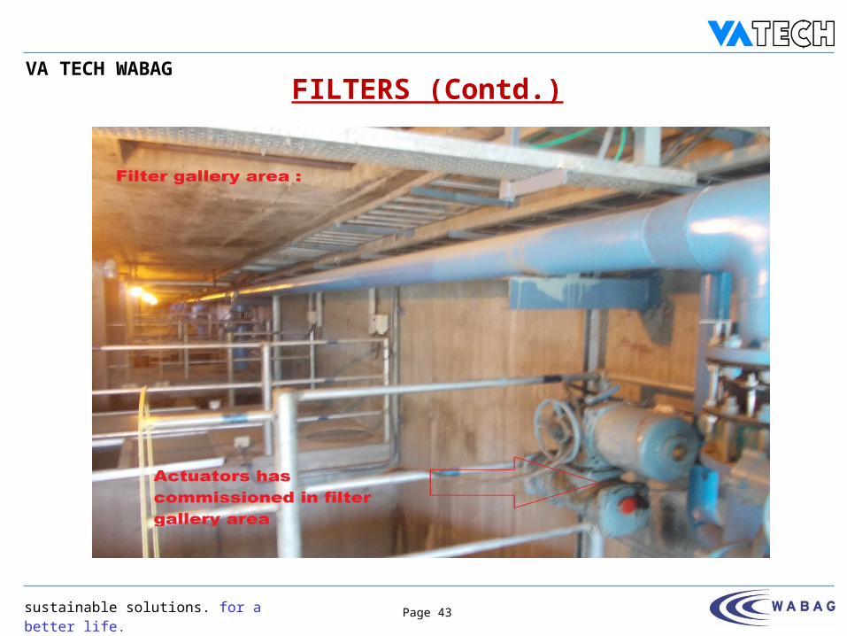
FILTERS (Contd.)
sustainable solutions. for a better life.
VA TECH WABAG
Page 44
P097-T0002-001
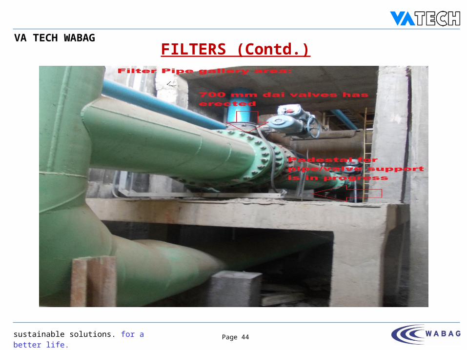
FILTERS (Contd.)
sustainable solutions. for a better life.
VA TECH WABAG
Page 45
P097-T0002-001
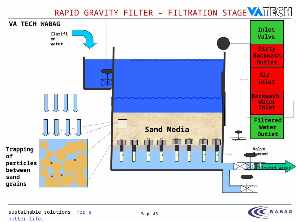
Sand Media
RAPID GRAVITY FILTER – FILTRATION STAGE
Clarified water
Valve Opened
Trapping of particles between sand grains
Inlet Valve
Filtered Water Outlet
Air Inlet
Backwash WaterInlet
Dirty Backwash
Outlet
Filtered Water

sustainable solutions. for a better life.
VA TECH WABAG
Page 46
P097-T0002-001
Dirty Sand Layer
Backwash water
Valve opened
Valve Closed
Valve Opened
Inlet
Valve
Filtered Water Outlet
Backwash WaterInlet
Dirty Backwash
Outlet
AirAir
supply stopped
Loosened Sand LayerFluidised Sand LayerCleaned Sand Layer
Air InletDirty
water out
VALVE CLOSED
RAPID GRAVITY FILTER – BACKWASH STAGE
sustainable solutions. for a better life.
VA TECH WABAG
Page 47
P097-T0002-001
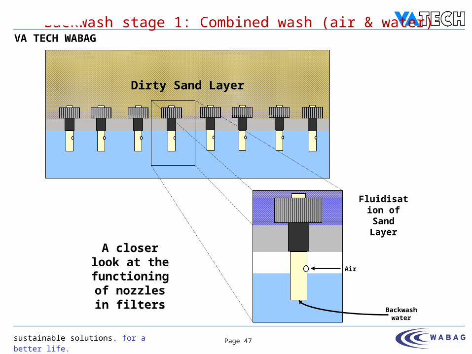
Dirty Sand Layer
Backwash stage 1: Combined wash (air & water)
Backwash water
Air
Fluidisation of Sand Layer
A closer look at the
functioning of nozzles in
filters

sustainable solutions. for a better life.
VA TECH WABAG
Page 48
P097-T0002-001
Fluidised Sand Layer
Back Wash Stage 2: Water Only
Backwash water
Cleansing of Sand Layer
Air flow stopped
rate increased
A closer look at the
functioning of nozzles in
filters
sustainable solutions. for a better life.
VA TECH WABAG
Page 49
P097-T0002-001
Three units (2 W+1 S) of twin lobe type Air Blowers each of capacity 4250 m³/h are provided.
Each filter outlet pipe work is connected to Clear Water Reservoir through a weir chamber. Chlorine solution is dosed (post-chlorination) at the inlet of the Clear Water Reservoir.
Filtered water samples are drawn from the common filter outlet with the help of sampling pump and is delivered to the laboratory for continuous measurement of filtered water quality.
Sampling point provision is also made to check the individual filters performance.
Level transmitter is provided in the common filter outlet. Flow meter is provided to monitor the treated water flow into the Clear Water
Reservoir.
FILTERS (Contd.)
sustainable solutions. for a better life.
VA TECH WABAG
Page 50
P097-T0002-001
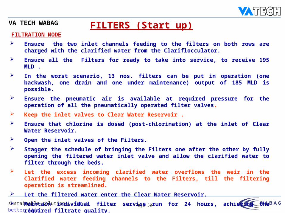
FILTRATION MODE Ensure the two inlet channels feeding to the filters on both rows are charged with the
clarified water from the Clariflocculator. Ensure all the Filters for ready to take into service, to receive 195 MLD . In the worst scenario, 13 nos. filters can be put in operation (one backwash, one drain and
one under maintenance) output of 185 MLD is possible. Ensure the pneumatic air is available at required pressure for the operation of all the
pneumatically operated filter valves. Keep the inlet valves to Clear Water Reservoir . Ensure that chlorine is dosed (post-chlorination) at the inlet of Clear Water Reservoir. Open the inlet valves of the Filters. Stagger the schedule of bringing the Filters one after the other by fully opening the filtered
water inlet valve and allow the clarified water to filter through the beds. Let the excess incoming clarified water overflows the weir in the Clarified water feeding
channels to the Filters, till the filtering operation is streamlined. Let the filtered water enter the Clear Water Reservoir. Maintain individual filter service run for 24 hours, achieving the required filtrate quality.
FILTERS (Start up)
sustainable solutions. for a better life.
VA TECH WABAG
Page 51
P097-T0002-001
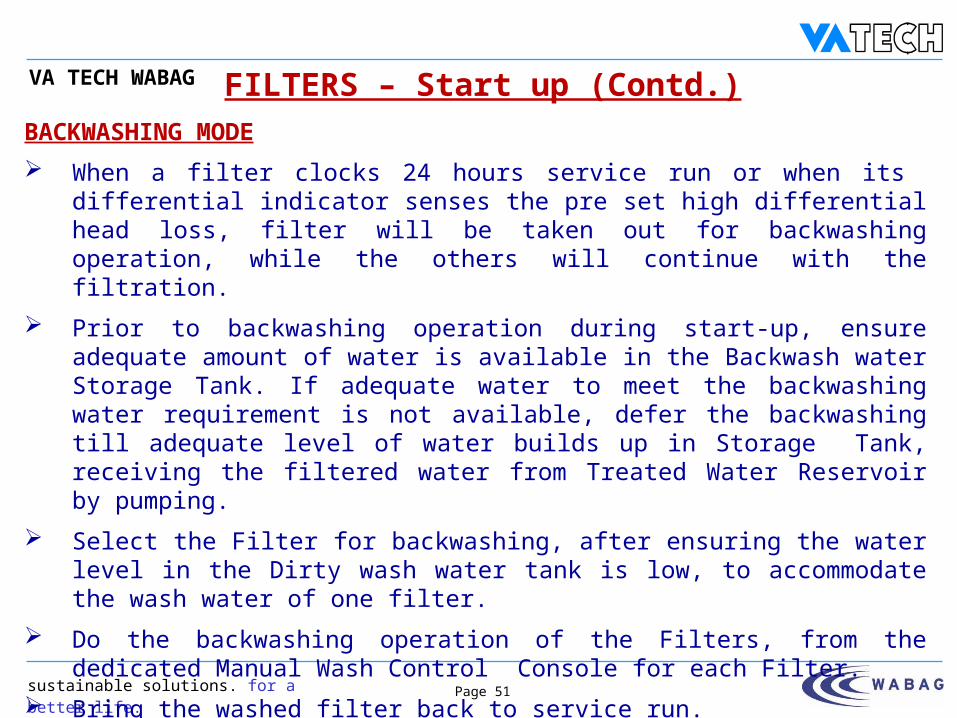
FILTERS – Start up (Contd.)BACKWASHING MODE When a filter clocks 24 hours service run or when its differential indicator senses
the pre set high differential head loss, filter will be taken out for backwashing operation, while the others will continue with the filtration.
Prior to backwashing operation during start-up, ensure adequate amount of water is available in the Backwash water Storage Tank. If adequate water to meet the backwashing water requirement is not available, defer the backwashing till adequate level of water builds up in Storage Tank, receiving the filtered water from Treated Water Reservoir by pumping.
Select the Filter for backwashing, after ensuring the water level in the Dirty wash water tank is low, to accommodate the wash water of one filter.
Do the backwashing operation of the Filters, from the dedicated Manual Wash Control Console for each Filter.
Bring the washed filter back to service run.
sustainable solutions. for a better life.
VA TECH WABAG
Page 52
P097-T0002-001
FILTERS – Shut down
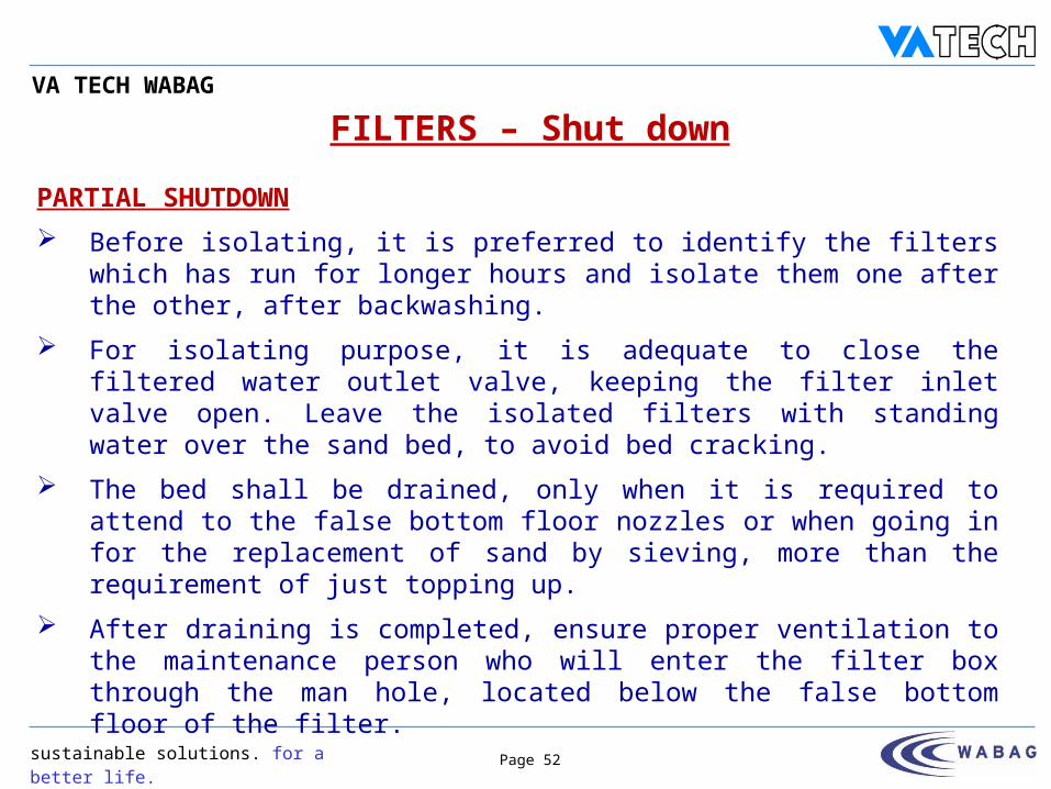
PARTIAL SHUTDOWN Before isolating, it is preferred to identify the filters which has run for longer
hours and isolate them one after the other, after backwashing. For isolating purpose, it is adequate to close the filtered water outlet valve,
keeping the filter inlet valve open. Leave the isolated filters with standing water over the sand bed, to avoid bed cracking.
The bed shall be drained, only when it is required to attend to the false bottom floor nozzles or when going in for the replacement of sand by sieving, more than the requirement of just topping up.
After draining is completed, ensure proper ventilation to the maintenance person who will enter the filter box through the man hole, located below the false bottom floor of the filter.
sustainable solutions. for a better life.
VA TECH WABAG
Page 53
P097-T0002-001
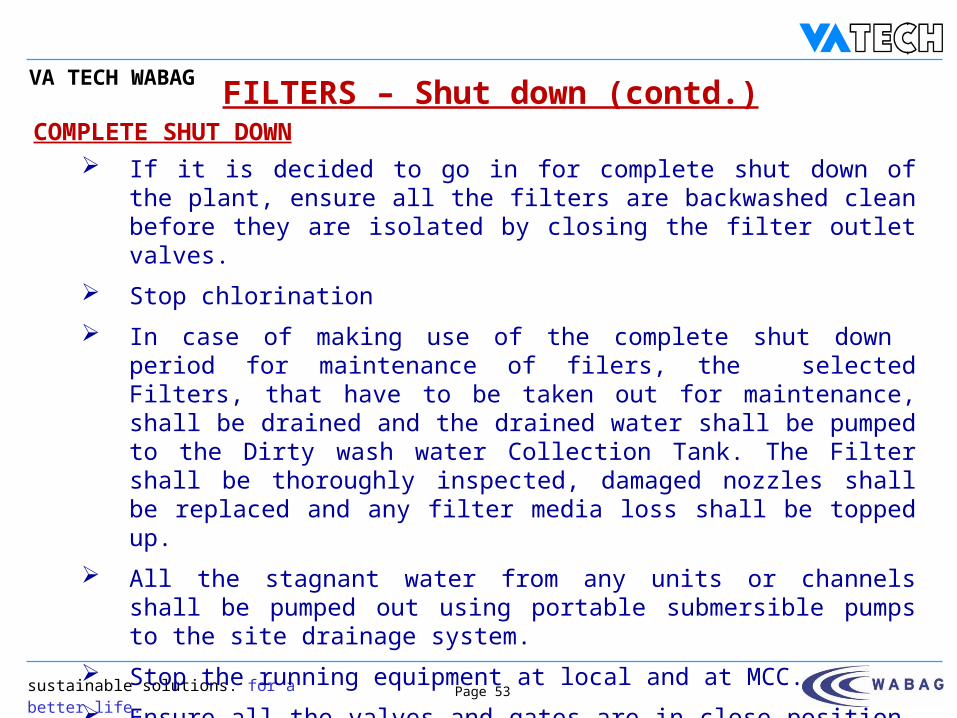
If it is decided to go in for complete shut down of the plant, ensure all the filters are backwashed clean before they are isolated by closing the filter outlet valves.
Stop chlorination In case of making use of the complete shut down period for maintenance
of filers, the selected Filters, that have to be taken out for maintenance, shall be drained and the drained water shall be pumped to the Dirty wash water Collection Tank. The Filter shall be thoroughly inspected, damaged nozzles shall be replaced and any filter media loss shall be topped up.
All the stagnant water from any units or channels shall be pumped out using portable submersible pumps to the site drainage system.
Stop the running equipment at local and at MCC. Ensure all the valves and gates are in close position, once the plant is
shut down.
COMPLETE SHUT DOWNFILTERS – Shut down (contd.)
sustainable solutions. for a better life.
VA TECH WABAG
Page 54
P097-T0002-001
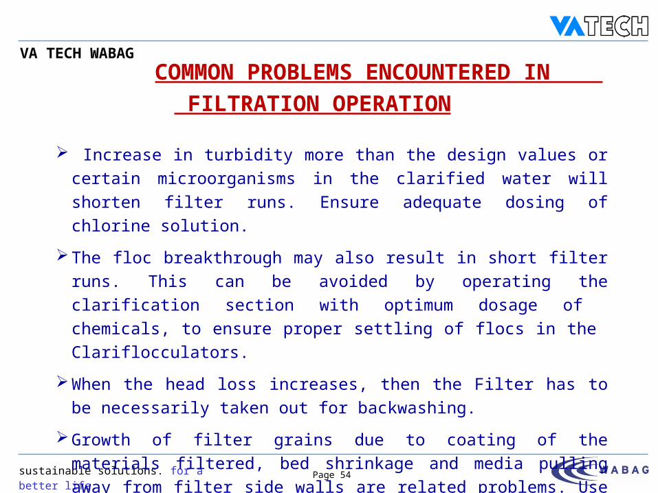
COMMON PROBLEMS ENCOUNTERED IN FILTRATION OPERATION
Increase in turbidity more than the design values or certain microorganisms in the clarified water will shorten filter runs. Ensure adequate dosing of chlorine solution.
The floc breakthrough may also result in short filter runs. This can be avoided by operating the clarification section with optimum dosage of chemicals, to ensure proper settling of flocs in the Clariflocculators.
When the head loss increases, then the Filter has to be necessarily taken out for backwashing.
Growth of filter grains due to coating of the materials filtered, bed shrinkage and media pulling away from filter side walls are related problems. Use of adequate backwash will avoid all these problems.
sustainable solutions. for a better life.
VA TECH WABAG
Page 55
P097-T0002-001
Mud ball due to general buildup of materials accumulate at or near the surface, leading to clogging of media. By proper coagulation and settling in the clarification stage, mud ball formation could be considerably reduced. Mud ball formation may not be experienced because of adequate design backwash rate. However prolonged air scouring followed by higher backwash shall be used, when mud ball formation is encountered.
Sand leakage is prevented by the careful selection of the sand size and the size of slots in the nozzles. However, the fines that may develop due to attrition can result in the downward migration and escape of fines with the filtered water. The topping up of lost media have to be taken up when it exceeds 2%.
Any observation of loss of media during backwashing shall be immediately attended by reducing backwash water rate. The backwash duration can be prolonged, if required, to effect complete back-washing of the bed.
COMMON PROBLEMS ENCOUNTERED IN FILTRATION OPERATION (contd.)
sustainable solutions. for a better life.
VA TECH WABAG
Page 56
P097-T0002-001
Air binding and subsequent release during service may not be a problem. Do not operate the filters with less liquid depth to overcome this problem.
Sometimes careless operation may lead to bumping or lifting of the filter beds when resuming filtration without going through the full backwash cycle. This practice should be discouraged as the filtrate water quality deteriorates considerably.
When slime or algae growths are noticed on filters, increase the dosage rate of chlorine solution to the extent required.
During air scouring if any improper distribution of air is noticed watch out for any deterioration of filtrate quality from that particular filter in the subsequent filtration cycles. If found beyond the acceptable levels of turbidity, then isolate the filter and rectify the defects such as replacement of worn out nozzle, or to clean the filter media free from stubborn choking.
COMMON PROBLEMS ENCOUNTERED IN FILTRATION OPERATION (contd.)
sustainable solutions. for a better life.
VA TECH WABAG
Page 57
P097-T0002-001
CLEAR WATER RESERVOIR
For chlorine dosing to the filtered water, diffuser arrangement is made. The Clear water Reservoir provides approximately 30 minutes retention time of 185 MLD for disinfection.
FRC monitoring to be done to check for residual chlorine in the filtered water at the outlet of Clear Water Reservoir.
sustainable solutions. for a better life.
VA TECH WABAG
Page 58
P097-T0002-001
A fully covered overhead backwash water Tank of RCC is provided with
adequate elevation. The size of the tank is 45.0 m x 7.3 m x 2.3 m LD. Two nos. overhead tank filling Pumps (1W+1S), which draw water from the
Filer outlet channel, are provided for supplying water to the Overhead backwash water tank. Each pump is having capacity of 760 m3/ h.
The tank is provided with a level switch for High High & Low Low levels with alarms and for tripping of the supply pumps at High High levels.
The duty pump is automatically started when a medium level is detected by the level transmitter.
Wash water is delivered direct to the filters by gravity. A flow indicator and integrator for indicating the wash water flow rate is provided in the backwash water line.
OVERHEAD BACKWASH WATER TANK
sustainable solutions. for a better life.
VA TECH WABAG
Page 59
P097-T0002-001
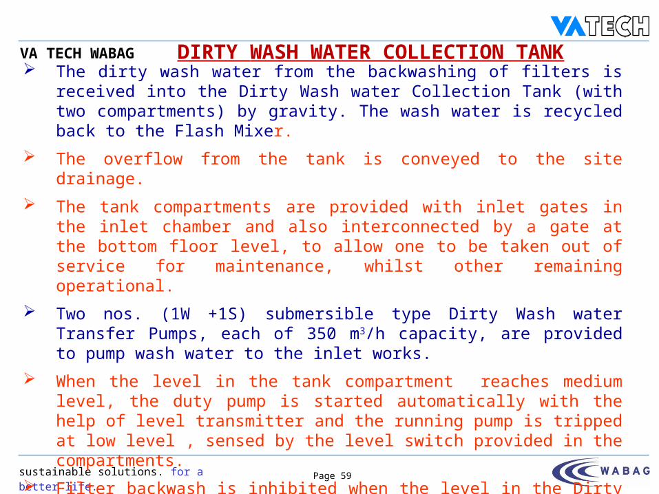
The dirty wash water from the backwashing of filters is received into the Dirty Wash water Collection Tank (with two compartments) by gravity. The wash water is recycled back to the Flash Mixer.
The overflow from the tank is conveyed to the site drainage. The tank compartments are provided with inlet gates in the inlet chamber and
also interconnected by a gate at the bottom floor level, to allow one to be taken out of service for maintenance, whilst other remaining operational.
Two nos. (1W +1S) submersible type Dirty Wash water Transfer Pumps, each of 350 m3/h capacity, are provided to pump wash water to the inlet works.
When the level in the tank compartment reaches medium level, the duty pump is started automatically with the help of level transmitter and the running pump is tripped at low level , sensed by the level switch provided in the compartments.
Filter backwash is inhibited when the level in the Dirty Wash water Collection Tank is High.
This tank also receives the filtrate of the Sludge Drying Beds.
DIRTY WASH WATER COLLECTION TANK
sustainable solutions. for a better life.
VA TECH WABAG
Page 60
P097-T0002-001
The settled sludge from the Clariflocculator is bled intermittently into the Sludge Sump.
The sludge from the Sludge Sump is pumped to eight nos. Sludge Drying Beds with the help of 2 nos. (1 W+1 S) Sludge pumps.
Each duty thickener feed pump is started automatically at medium level detected by level transmitter.
The running thickener feed pumps are tripped at low level sensed by level switch.
When the sludge level reaches high in the Sludge Sump, clariflocculator de-sludging schedule is inhibited.
When one bed is out of service for maintenance, isolate the bed with the gate provided.
SLUDGE SUMP

sustainable solutions. for a better life.
VA TECH WABAG
Page 61
P097-T0002-001
ALUMINIUM SULPHATE DOSING SYSTEM Aluminium Sulphate (Alum) is used for the coagulation of suspended solids
in the raw water.
Two nos. (1 W+ 1 S) each of having size 3.6 m x 2.6 m LD, is provided on the basis of 23 hours dosing requirement.
To prepare required strength of Alum (10%) and for the complete dissolution of alum, dosing tank is equipped with alum mixing agitators.
The tanks are constructed in RCC with acid alkali proof tile lining on inside surface.
The tank is provided with a dissolving basket and the alum and service water is added into the dissolving tray.
3 nos. alum dosing pumps of 2600 LPH capacity (2W+1S) are provided to transfer to the dosing point at the upstream of the parshall flume.
sustainable solutions. for a better life.
VA TECH WABAG
Page 62
P097-T0002-001
ALUMINIUM SULPHATE DOSING SYSTEM (contd.)
The level indicator/ transmitter is provided in the respective tanks and is interlocked with 3 nos. alum dosing pumps.
The alum solution preparation and dosing is manually controlled from local control panel with the help of push button stations.
Each dosing tank is provided with a level switch for giving Low level alarms.
The running alum feed pump and respective agitator are tripped at low level with the help of level switch.
sustainable solutions. for a better life.
VA TECH WABAG
Page 63
P097-T0002-001
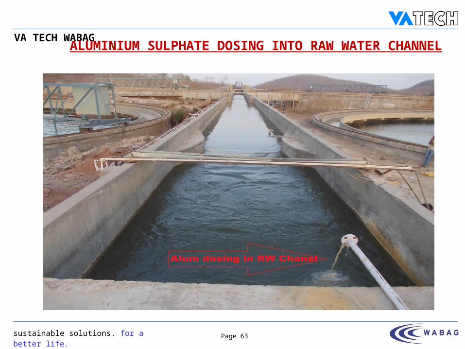
ALUMINIUM SULPHATE DOSING INTO RAW WATER CHANNEL
sustainable solutions. for a better life.
VA TECH WABAG
Page 64
P097-T0002-001
LIME DOSING SYSTEM Lime is used to increase the alkalinity of the raw water.
Two nos. (1 W+ 1 S) each of having size 3.6 m x 2.6 m LD, is provided on the basis of 23 hours dosing requirement.
To prepare required strength of Lime (5%) and for the complete dissolution of lime, dosing tank is equipped with lime mixing agitators.
The tanks are constructed in RCC with epoxy coating on inside surface.
The tank is provided with a dissolving basket and the lime and service water is added into the dissolving tray.
3 nos. lime dosing pumps of 10 m3/h capacity (2W+1S) are provided to transfer to the dosing point at the upstream of the parshall flume.
sustainable solutions. for a better life.
VA TECH WABAG
Page 65
P097-T0002-001
LIME DOSING SYSTEM (contd.)
The level indicator/ transmitter is provided in the respective tanks and is interlocked with 3 nos. lime dosing pumps.
The lime solution preparation and dosing is manually controlled from local control panel with the help of push button stations.
Each dosing tank is provided with a level switch for giving Low level alarms.
The running lime feed pump and respective agitator are tripped at low level with the help of level switch.
sustainable solutions. for a better life.
VA TECH WABAG
Page 66
P097-T0002-001
CHLORINE PLANT The Chlorine Plant and its equipments are located in a self contained
separate building and consists of
a) Drum Roomb) Chlorinator and Ejector Room
Two no. chlorinator of capacity 56.25 kg/h is provided for pre-chlorination for dosing chlorine at 2mg/L and post chlorination for dosing chlorine at Chlorine 3 mg/L.
All the chlorinators are vacuum operated with remote operated ejector.
Clear water from clear water pump house is used as motive water to dose the chlorine using booster pumps (1W+1S) which has the capacity of 15 m3/h.
sustainable solutions. for a better life.
VA TECH WABAG
Page 67
P097-T0002-001
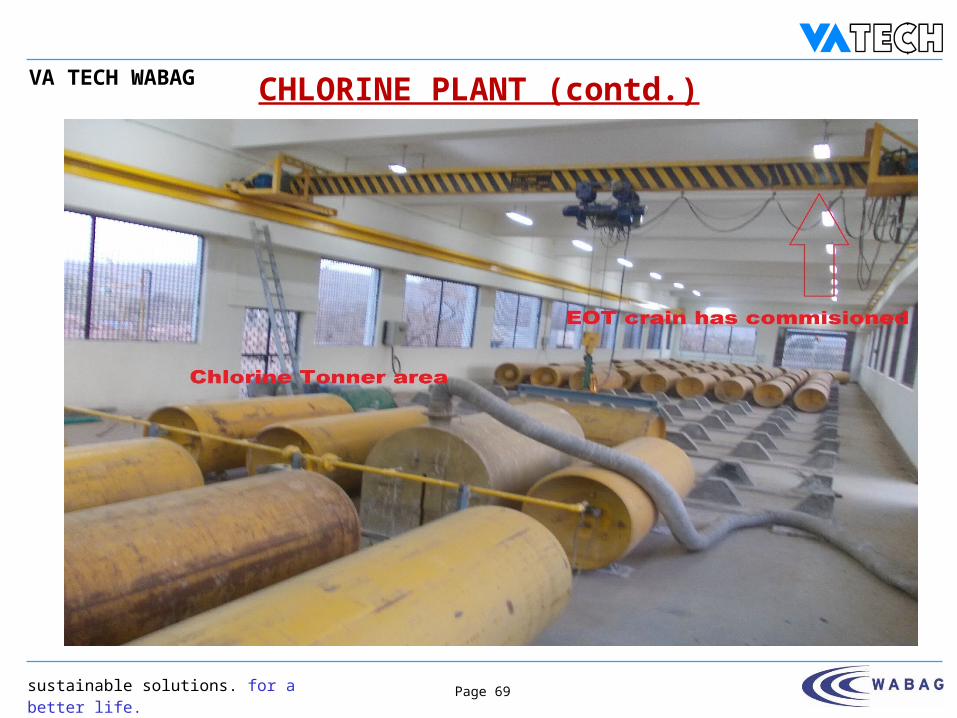
CHLORINE PLANT (contd.) The chlorine gas is withdrawn from chlorine ton containers gets filtered
through gas filter and reaches the chlorine ejector.
The motive water creates vacuum in the ejector and the chlorine gas gets mixed with the motive water to form a solution of chlorine. This chlorinated water is added after cascade aerator and at the clear water channel before the clear water sump.
An automatic changeover system is provided at the chlorine withdrawal system, such that when one ton container is empty, the other toner comes online automatically and hence the chlorine supply is continuous.
The two delivery pipe lines are interconnected and an arrangement of isolating valves is provided to permit the use of any two of the four chlorinators independently for pre-chlorination and/or post chlorination.
Chlorine leak detectors (3 nos.) are provided for monitoring the abnormal chlorine gas concentration and for indicating chlorine gas leakage. The chlorine room is built in such a way that it can store 93 nos. ton containers.
sustainable solutions. for a better life.
VA TECH WABAG
Page 68
P097-T0002-001
CHLORINE PLANT (contd.)
The chlorine-dosing rate for pre-chlorination is regulated by manually adjusting the chlorine gas control valve of the chlorinator.
For post-chlorination, select one motive water pump. Keep the inlet valve of the standby chlorinator and ejector closed.
The chlorine dose for post-chlorination is regulated w. r. t residual chlorine to be maintained in the treated water.
sustainable solutions. for a better life.
VA TECH WABAG
Page 69
P097-T0002-001
CHLORINE PLANT (contd.)

sustainable solutions. for a better life.
VA TECH WABAG
Page 70
P097-T0002-001
CHLORINE PLANT (contd.)
sustainable solutions. for a better life.
VA TECH WABAG
Page 71
P097-T0002-001
SECTION – 1 C
Emergency Procedures

sustainable solutions. for a better life.
VA TECH WABAG
Page 72
P097-T0002-001
EMERGENCY PROCEDURES
IN CASE OF POWER FAILURE
If raw water is still received in the plant, allow the water to pass through the entire plant.
- Continue dosing the alum and lime solution from the available stock.
- De-sludge the Clarifiers manually, as per the routine, using manual override facility of sludge bleed valves.
- Let the filters be in service mode.
sustainable solutions. for a better life.
VA TECH WABAG
Page 73
P097-T0002-001
EMERGENCY PROCEDURES (Contd.)
If raw water has stopped- Stop the alum and lime dosing.
- De-sludge the Clarifiers manually, as per the routine, using manual override facility of sludge bleed valves, to complete one cycle desludging operation.
- Isolate the filters by closing the filtered water outlet valves, manually, to avoid the filters from running dry.
Under power failure conditions, all the drives shall be isolated locally and restarted on resumption of power, ensuring no overload conditions.
sustainable solutions. for a better life.
VA TECH WABAG
Page 74
P097-T0002-001
EMERGENCY PROCEDURES (Contd.) Backwashing during failure of auto operation of valve- When the motorized operation is non-functional and manual operation
needs to be carried out for the backwashing of Filters, ensure the following:- Isolate the air supply and vent out the air from the actuator.
- Position two operators, one at the control desk of the Filter (Operator 1) which is to be taken up for backwashing and the other (Operator 2), for backwash flow control.
- Let the operator at the control desk initiate the backwash operation of the selected Filter, sequentially.
- When the Conjunctive air plus water wash is to be commenced, Operator 1 will convey the message to the Operator 2.
sustainable solutions. for a better life.
VA TECH WABAG
Page 75
P097-T0002-001
EMERGENCY PROCEDURES (Contd.) Backwashing during failure of auto operation (Contd.)- Operator 2 will close the backwash valve provided with the help of hand
wheel. Operate the hand wheel manually.
- The hand wheel needs to be operated to maintain the flow as necessary.
- The manual operation of the valves at the pipe gallery for carrying out the backwashing operation shall be attended to, by the Operator 1.
- When the duration of final wash step is over, close the B/W valve.
- A close coordination is required between the two operators, to complete the backwashing operation, manually.