training session on energy...
TRANSCRIPT

© UNEP 2006
1
Training Session on Energy
Equipment
Furnaces and
RefractoriesPresentation from the
“Energy Efficiency Guide for Industry in Asia”
www.energyefficiencyasia.org
© UNEP 2006
2
Training Agenda: Steam
Introduction
Type of furnaces and refractory
materials
Assessment of furnaces
Energy efficiency opportunities
© UNEP 2006
3
Introduction
• Equipment to melt metals
• Casting
• Change shape
• Change properties
• Type of fuel important
• Mostly liquid/gaseous fuel or electricity
• Low efficiencies due to
• High operating temperature
• Emission of hot exhaust gases
What is a Furnace?

© UNEP 2006
4
Introduction
Furnace Components
(The Carbon Trust)
Furnace chamber:
constructed of
insulating materials
Hearth: support or
carry the steel.
Consists of
refractory materials
Burners: raise or
maintain chamber
temperature
Chimney:
remove
combustion
gases
Charging & discharging doors for
loading & unloading stock
Charging & discharging doors for
loading & unloading stock

© UNEP 2006
5
Introduction
Materials that
• Withstand high temperatures and sudden
changes
• Withstand action of molten slag, glass, hot
gases etc
• Withstand load at service conditions
• Withstand abrasive forces
• Conserve heat
• Have low coefficient of thermal expansion
• Will not contaminate the load
What are Refractories:

© UNEP 2006
6
Introduction
Refractories
Refractory lining of a
furnace arc
Refractory walls of a
furnace interior with
burner blocks
(BEE India, 2005)
© UNEP 2006
7
Introduction
• Melting point• Temperature at which a ‘test pyramid’ (cone)
fails to support its own weight
• Size• Affects stability of furnace structure
• Bulk density• Amount of refractory material within a
volume (kg/m3)
• High bulk density = high volume stability, heat capacity and resistance
Properties of Refractories

© UNEP 2006
8
Introduction
• Porosity• Volume of open pores as % of total refractory
volume
• Low porosity = less penetration of molten material
• Cold crushing strength• Resistance of refractory to crushing
• Creep at high temperature• Deformation of refractory material under
stress at given time and temperature
Properties of Refractories

© UNEP 2006
9
Introduction
• Pyrometric cones• Used in ceramic industries
to test ‘refractoriness’ of refractory bricks
• Each cone is mix of oxidesthat melt at specific temperatures
Properties of Refractories
• Pyrometric Cone Equivalent (PCE)
• Temperature at which the refractory brick and
the cone bend
• Refractory cannot be used above this temp
(BEE India, 2004)

© UNEP 2006
10
Introduction
• Volume stability, expansion &
shrinkage
• Permanent changes during refractory service
life
• Occurs at high temperatures
• Reversible thermal expansion
• Phase transformations during heating and
cooling
Properties of Refractories
© UNEP 2006
11
Introduction
• Thermal conductivity• Depends on composition and silica content
• Increases with rising temperature
• High thermal conductivity: • Heat transfer through brickwork required
• E.g. recuperators, regenerators
• Low thermal conductivity:• Heat conservation required (insulating
refractories)
• E.g. heat treatment furnaces
Properties of Refractories

© UNEP 2006
12
Training Agenda: Steam
Introduction
Type of furnaces and refractory
materials
Assessment of furnaces
Energy efficiency opportunities
© UNEP 2006
13
Type of Furnaces and Refractories
• Type of Furnaces
• Forging furnaces
• Re-rolling mill furnaces
• Continuous reheating furnaces
• Type of Refractories
• Type of Insulating Materials
© UNEP 2006
14
Type of Furnaces and Refractories
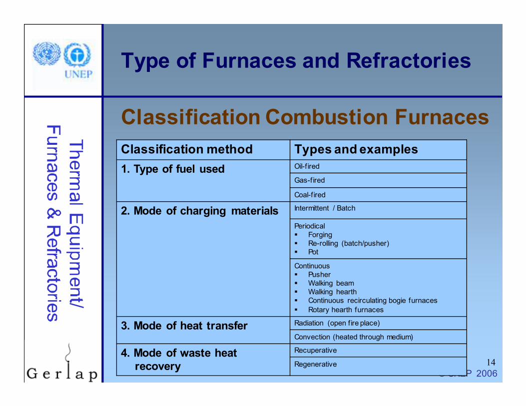
Classification Combustion Furnaces
Classification method Types and examples
1. Type of fuel used Oil-f ired
Gas-fired
Coal-f ired
2. Mode of charging materials Intermittent / Batch
Periodical
� Forging
� Re-rolling (batch/pusher)
� Pot
Continuous
� Pusher
� Walking beam
� Walking hearth
� Continuous recirculating bogie furnaces
� Rotary hearth furnaces
3. Mode of heat transfer Radiation (open f ire place)
Convection (heated through medium)
4. Mode of waste heat
recovery
Recuperative
Regenerative

© UNEP 2006
15
Type of Furnaces and Refractories
• Used to preheat billets/ingots
• Use open fireplace system with radiation heat transmission
• Temp 1200-1250 oC
• Operating cycle• Heat-up time
• Soaking time
• Forging time
• Fuel use: depends on material and number of reheats
Forging Furnace

© UNEP 2006
16
Type of Furnaces and Refractories
• Box type furnace
• Used for heating up scrap/ingots/billets
• Manual charge / discharge of batches
• Temp 1200 oC
• Operating cycle: heat-up, re-rolling
• Output 10 - 15 tons/day
• Fuel use: 180-280 kg coal/ton material
Re-rolling Mill Furnace – Batch type

© UNEP 2006
17
Type of Furnaces and Refractories
• Not batch, but continuous charge and
discharge
• Temp 1250 oC
• Operating cycle: heat-up, re-rolling
• Output 20-25 tons/day
• Heat absorption by material is slow,
steady, uniform
Re-rolling Mill Furnace –
Continuous pusher type

© UNEP 2006
18
Type of Furnaces and Refractories
• Continuous material flow
• Material temp 900 – 1250 oC
• Door size minimal to avoid air infiltration
• Stock kept together and pushed• Pusher type furnaces
• Stock on moving hearth or structure• Walking beam, walking hearth, continuous
recirculating bogie, rotary hearth furnaces
Continuous Reheating Furnaces

© UNEP 2006
19
Type of Furnaces and Refractories
1. Pusher Furnace
• Pushers on ‘skids’ (rails) with water-cooled
support push the stock
• Hearth sloping towards discharge end
• Burners at discharge
end or top and/or
bottom
• Chimney with
recuperator for
waste heat recovery
(The Carbon Trust, 1993)
Continuous Reheating Furnaces

© UNEP 2006
20
Type of Furnaces and Refractories
2. Walking Beam Furnace
• Stock placed on stationary ridges
• Walking beams raise the stock and move forwards
• Walking beams lower stock onto stationary ridges
at exit
• Stock is removed
• Walking beams
return to furnace
entrance
(The Carbon Trust, 1993)
Continuous Reheating Furnaces
© UNEP 2006
21
Type of Furnaces and Refractories
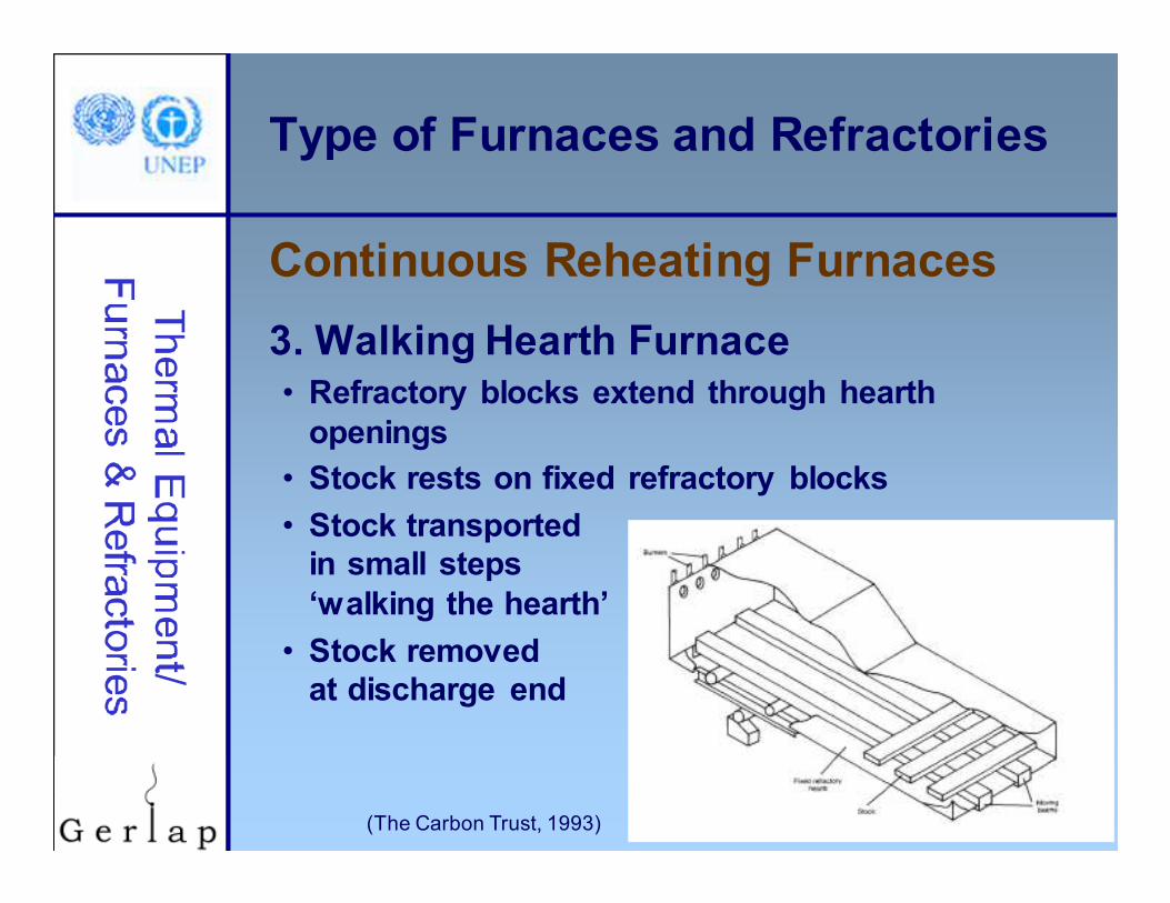
3. Walking Hearth Furnace
• Refractory blocks extend through hearth
openings
• Stock rests on fixed refractory blocks
• Stock transported
in small steps
‘walking the hearth’
• Stock removed
at discharge end
(The Carbon Trust, 1993)
Continuous Reheating Furnaces
© UNEP 2006
22
Type of Furnaces and Refractories
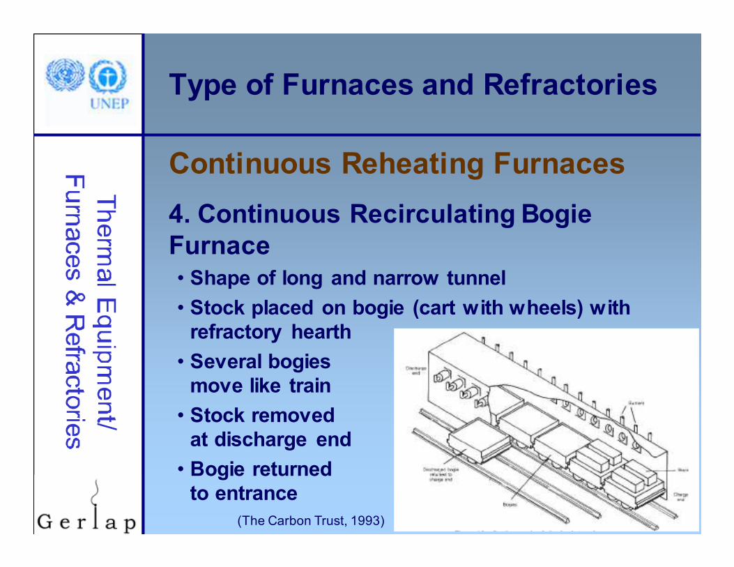
4. Continuous Recirculating Bogie
Furnace
• Shape of long and narrow tunnel
• Stock placed on bogie (cart with wheels) with
refractory hearth
• Several bogies
move like train
• Stock removed
at discharge end
• Bogie returned
to entrance
(The Carbon Trust, 1993)
Continuous Reheating Furnaces

© UNEP 2006
23
Type of Furnaces and Refractories
5. Rotary Hearth Furnace
• Walls and roof remain stationary
• Hearth moves in circle on rollers
• Stock placed on hearth
• Heat moves in
opposite direction
of hearth
• Temp 1300oC
(The Carbon Trust, 1993)
Continuous Reheating Furnaces

© UNEP 2006
24
Type of Furnaces and Refractories
Classification of Refractories
Classification method Examples
Chemical composition
ACID, which readily combines with bases Silica, Semisilica, Aluminosilicate
BASIC, which consists mainly of metallic oxides that resist the action of bases
Magnesite, Chrome-magnesite, Magnesite-chromite, Dolomite
NEUTRAL, which does not combine with acids nor bases
Fireclay bricks, Chrome, Pure Alumina
Special Carbon, Silicon Carbide, Zirconia
End use Blast furnace casting pit
Method of manufacture Dry press process, fused cast, hand moulded, formed normal, fired or chemically
bonded, unformed (monolithics, plastics,
ramming mass, gunning castable, spraying)

© UNEP 2006
25
Type of Furnaces and Refractories
• Common in industry: materials available and inexpensive
• Consist of aluminium silicates
• Decreasing melting point (PCE) with increasing impurity and decreasing AL2O3
Fireclay Refractories
• 45 - 100% alumina
• High alumina % = high refractoriness
• Applications: hearth and shaft of blast furnaces, ceramic kilns, cement kilns, glass tanks
High Alumina Refractories

© UNEP 2006
26
Type of Furnaces and Refractories
• >93% SiO2 made from quality rocks
• Iron & steel, glass industry
• Advantages: no softening until fusion point is
reached; high refractoriness; high resistance to
spalling, flux and slag, volume stability
Silica Brick
• Chemically basic: >85% magnesium oxide
• Properties depend on silicate bond concentration
• High slag resistance, especially lime and iron
Magnesite

© UNEP 2006
27
Type of Furnaces and Refractories
• Chrome-magnesite
• 15-35% Cr2O3 and 42-50% MgO
• Used for critical parts of high temp furnaces
• Withstand corrosive slags
• High refractories
• Magnesite-chromite
• >60% MgO and 8-18% Cr2O3
• High temp resistance
• Basic slags in steel melting
• Better spalling resistance
Chromite Refractories
© UNEP 2006
28
Type of Furnaces and Refractories
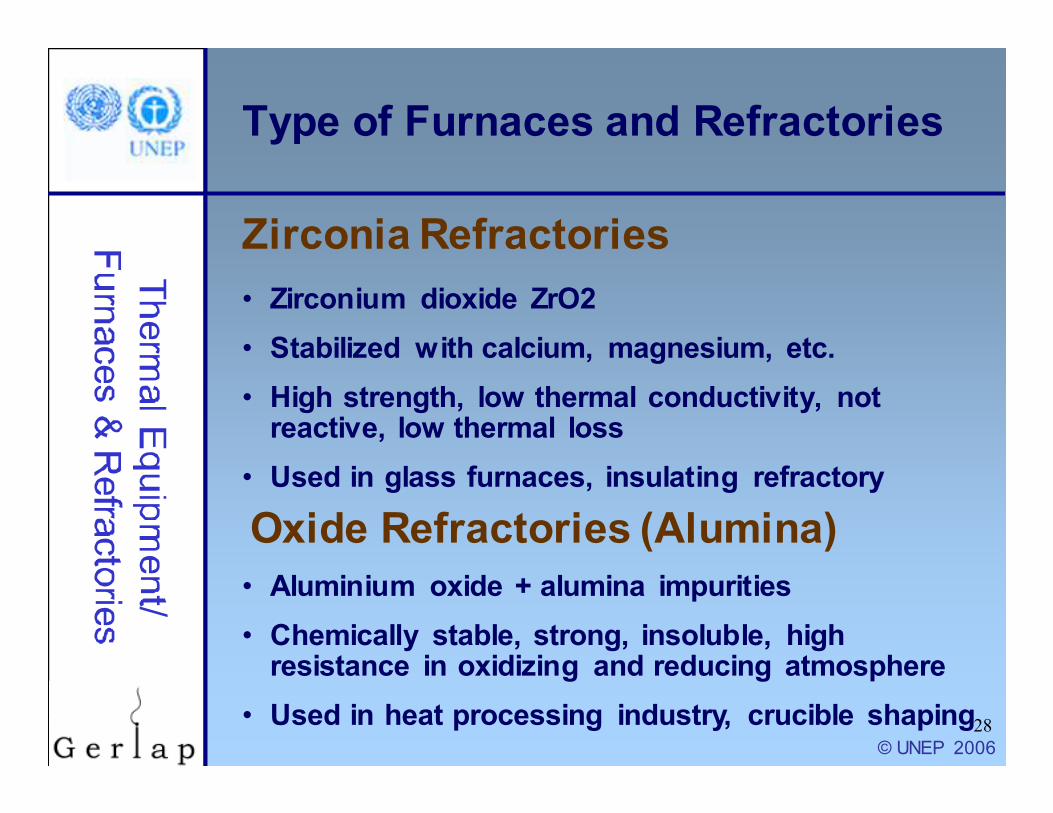
• Zirconium dioxide ZrO2
• Stabilized with calcium, magnesium, etc.
• High strength, low thermal conductivity, not reactive, low thermal loss
• Used in glass furnaces, insulating refractory
Zirconia Refractories
• Aluminium oxide + alumina impurities
• Chemically stable, strong, insoluble, high resistance in oxidizing and reducing atmosphere
• Used in heat processing industry, crucible shaping
Oxide Refractories (Alumina)

© UNEP 2006
29
Type of Furnaces and Refractories
• Single piece casts in equipment shape
• Replacing conventional refractories
• Advantages• Elimination of joints
• Faster application
• Heat savings
• Better spalling resistance
• Volume stability
• Easy to transport, handle, install
• Reduced downtime for repairs
Monolithics
© UNEP 2006
30
Type of Furnaces and Refractories
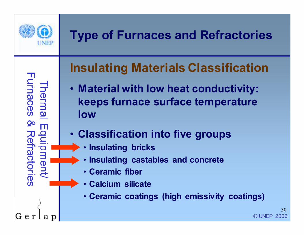
• Material with low heat conductivity:
keeps furnace surface temperature
low
• Classification into five groups
• Insulating bricks
• Insulating castables and concrete
• Ceramic fiber
• Calcium silicate
• Ceramic coatings (high emissivity coatings)
Insulating Materials Classification
© UNEP 2006
31
Type of Furnaces and Refractories
• Consist of
• Insulation materials used for making piece
refractories
• Concretes contain Portland or high-alumina
cement
• Application
• Monolithic linings of furnace sections
• Bases of tunnel kiln cars in ceramics
industry
Castables and Concretes

© UNEP 2006
32
Type of Furnaces and Refractories
• Thermal mass insulation materials
• Manufactured by blending alumina
and silica
• Bulk wool to make insulation
products
• Blankets, strips, paper, ropes, wet felt etc
• Produced in two temperature grades
Ceramic Fibers

© UNEP 2006
33
Type of Furnaces and Refractories
• Low thermal conductivity
• Light weight
• Lower heat storage
• Thermal shock resistant
• Chemical resistance
• Mechanical resilience
• Low installation costs
• Ease of maintenance
• Ease of handling
• Thermal efficiency
Ceramic Fibers
Remarkable properties and benefits
• Lightweight furnace
• Simple steel fabrication
work
• Low down time
• Increased productivity
• Additional capacity
• Low maintenance costs
• Longer service life
• High thermal efficiency
• Faster response

© UNEP 2006
34
Type of Furnaces and Refractories
• Emissivity: ability to absorb and
radiate heat
• Coatings applied to interior furnace
surface:
• emissivity stays constant
• Increase emissivity from 0.3 to 0.8
• Uniform heating and extended refractory life
• Fuel reduction by up to 25-45%
High Emissivity Coatings

© UNEP 2006
35
Type of Furnaces and Refractories
High Emissivity Coatings
(BEE India, 2005)

© UNEP 2006
36
Training Agenda: Steam
Introduction
Type of furnaces and refractory
materials
Assessment of furnaces
Energy efficiency opportunities
© UNEP 2006
37
Assessment of Furnaces
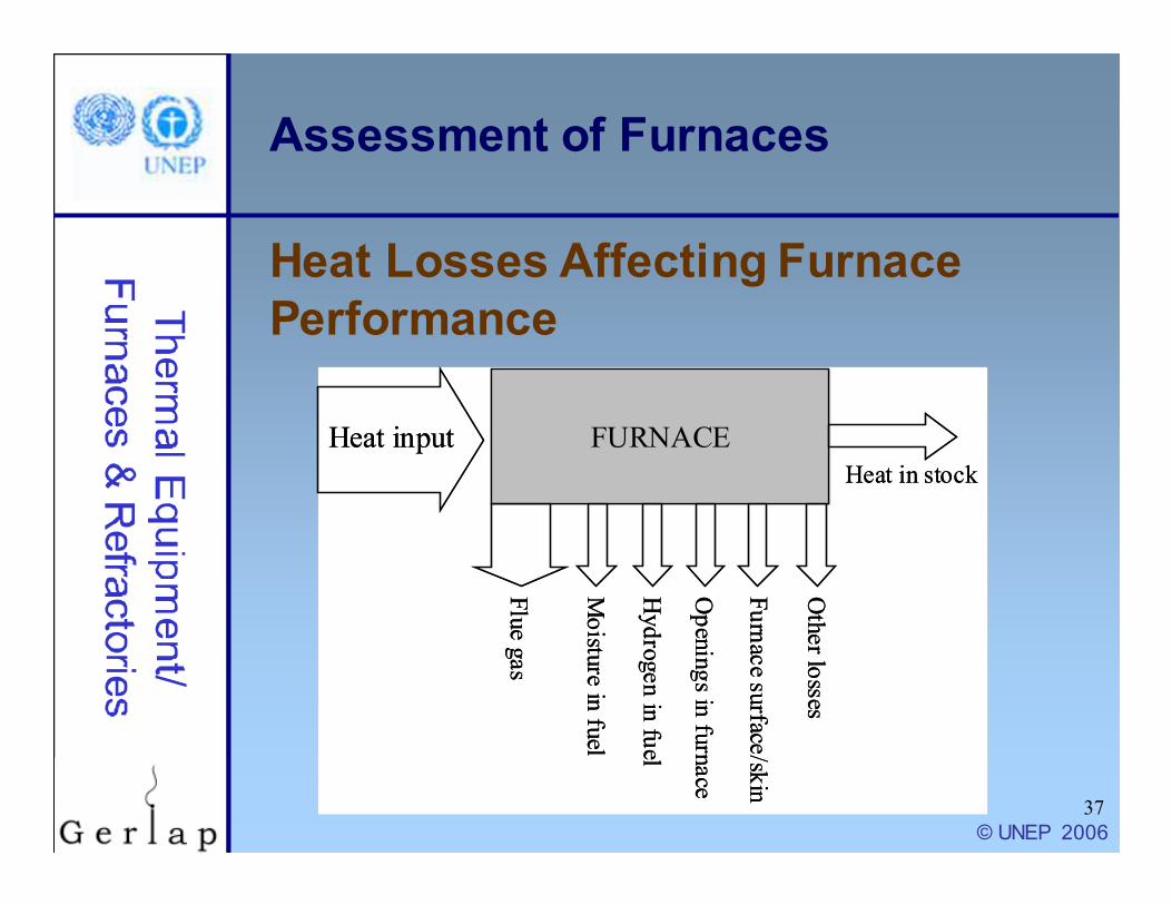
Heat Losses Affecting Furnace
Performance
FURNACE
Flue gas
Moisture in
fuel
Openings in furnace
Furnace su
rface/skin
Other losses
Heat input
Heat in stock
Hydrogen in fuel
FURNACE
Flue gas
Moisture in
fuel
Openings in furnace
Furnace su
rface/skin
Other losses
Heat input
Heat in stock
Hydrogen in fuel

© UNEP 2006
38
Assessment of Furnaces
Instruments to Assess Furnace
PerformanceParameters
to be measured
Location of
measurement
Instrument
required
Required
Value
Furnace soaking zone
temperature (reheating
furnaces)
Soaking zone and side
w all
Pt/Pt-Rh thermocouple
w ith indicator and
recorder
1200-1300oC
Flue gas temperature In duct near the discharge
end, and entry to
recuperator
Chromel Alummel
Thermocouple w ith
indicator
700oC max.
Flue gas temperature After recuperator Hg in steel thermometer 300oC (max)
Furnace hearth pressure
in the heating zone
Near charging end and
side w all over the hearth
Low pressure ring gauge +0.1 mm of Wc
Oxygen in f lue gas In duct near the discharge
end
Fuel eff iciency monitor for
oxygen and temperature
5% O2
Billet temperature Portable Infrared pyrometer or
optical pyrometer
-

© UNEP 2006
39
Assessment of Furnaces
Direct Method
• Thermal efficiency of furnace
= Heat in the stock / Heat in fuel
consumed for heating the stock
• Heat in the stock Q:
Q = m x Cp (t1 – t2)
Calculating Furnace Performance
Q = Quantity of heat of stock in kCal m = Weight of the stock in kg
Cp= Mean specific heat of stock in kCal/kg oC
t1 = Final temperature of stock in oC
t2 = Initial temperature of the stock before it enters the furnace in oC

© UNEP 2006
40
Assessment of Furnaces
Direct Method - example
• Heat in the stock Q = • m x Cp (t1 – t2)
• 6000 kg X 0.12 X (1340 – 40)
• 936000 kCal
• Efficiency =• (heat input / heat output) x 100
• [936000 / (368 x 10000) x 100 = 25.43%
• Heat loss = 100% - 25% = 75%
Calculating Furnace Performance
m = Weight of the stock = 6000
kg
Cp= Mean
specific heat of
stock = 0.12 kCal/kg oC
t1 = Final
temperature of
stock = 1340 oC
t2 = Initial temperature of
the stock = 40 oC
Calorific value of
oil = 10000
kCal/kgFuel consumption
= 368 kg/hr
© UNEP 2006
41
Assessment of Furnaces
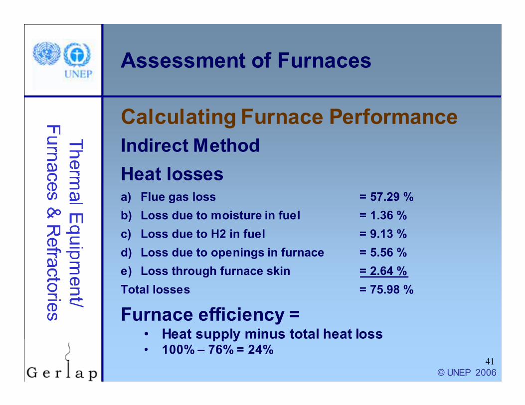
Indirect Method
Heat lossesa) Flue gas loss = 57.29 %
b) Loss due to moisture in fuel = 1.36 %
c) Loss due to H2 in fuel = 9.13 %
d) Loss due to openings in furnace = 5.56 %
e) Loss through furnace skin = 2.64 %
Total losses = 75.98 %
Furnace efficiency =• Heat supply minus total heat loss• 100% – 76% = 24%
Calculating Furnace Performance

© UNEP 2006
42
Assessment of Furnaces
Typical efficiencies for industrial furnaces
Calculating Furnace Performance
Furnace type Thermal efficiencies (%)
1) Low Temperature furnaces
a. 540 – 980 oC (Batch type) 20-30
b. 540 – 980 oC (Continous type) 15-25
c. Coil Anneal (Bell) radiant type 5-7
d. Strip Anneal Muffle 7-12
2) High temperature furnaces
a. Pusher,Rotary 7-15
b. Batch forge 5-10
3) Continuous Kiln
a. Hoffman 25-90
b. Tunnel 20-80
4) Ovens
a. Indirect fired ovens (20 oC –370 oC) 35-40
b. Direct fired ovens (20 oC –370 oC) 35-40
© UNEP 2006
43
Training Agenda: Steam
Introduction
Type of furnaces and refractory
materials
Assessment of furnaces
Energy efficiency opportunities
© UNEP 2006
44
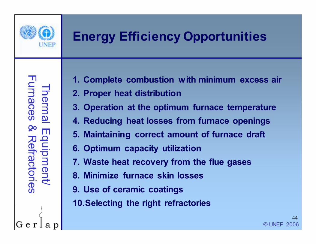
Energy Efficiency Opportunities
1. Complete combustion with minimum excess air
2. Proper heat distribution
3. Operation at the optimum furnace temperature
4. Reducing heat losses from furnace openings
5. Maintaining correct amount of furnace draft
6. Optimum capacity utilization
7. Waste heat recovery from the flue gases
8. Minimize furnace skin losses
9. Use of ceramic coatings
10.Selecting the right refractories

© UNEP 2006
45
Energy Efficiency Opportunities
• Importance of excess air• Too much: reduced flame temp, furnace
temp, heating rate
• Too little: unburnt in flue gases, scale losses
• Indication of excess air: actual air / theoretical combustion air
• Optimizing excess air• Control air infiltration
• Maintain pressure of combustion air
• Ensure high fuel quality
• Monitor excess air
1. Complete Combustion with
Minimum Excess Air

© UNEP 2006
46
Energy Efficiency Opportunities
When using burners
• Flame should not touch or be obstructed
• No intersecting flames from different burners
• Burner in small furnace should face upwards
but not hit roof
• More burners with less capacity (not one big
burner) in large furnaces
• Burner with long flame to improve uniform
heating in small furnace
2. Proper Heat Distribution

© UNEP 2006
47
Energy Efficiency Opportunities
• Operating at too high temperature: heat
loss, oxidation, decarbonization, refractory stress
• Automatic controls eliminate human
error
3. Operate at Optimum Furnace
Temperature
Slab Reheating furnaces 1200oC
Rolling Mill furnaces 1200oC
Bar furnace for Sheet Mill 800oC
Bogie type annealing furnaces 650oC –750oC
© UNEP 2006
48
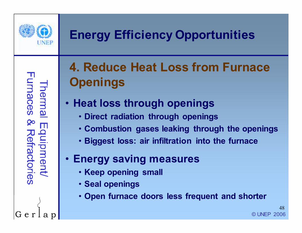
Energy Efficiency Opportunities
• Heat loss through openings
• Direct radiation through openings
• Combustion gases leaking through the openings
• Biggest loss: air infiltration into the furnace
• Energy saving measures
• Keep opening small
• Seal openings
• Open furnace doors less frequent and shorter
4. Reduce Heat Loss from Furnace
Openings

© UNEP 2006
49
Energy Efficiency Opportunities
• Negative pressure in furnace: air
infiltration
• Maintain slight positive pressure
• Not too high pressure difference: air
ex-filtration
Heat loss only about 1% if furnace
pressure is controlled properly!
5. Correct Amount of Furnace Draft

© UNEP 2006
50
Energy Efficiency Opportunities
• Optimum load
• Underloading: lower efficiency
• Overloading: load not heated to right temp
• Optimum load arrangement
• Load receives maximum radiation
• Hot gases are efficiently circulated
• Stock not placed in burner path, blocking flue
system, close to openings
• Optimum residence time
• Coordination between personnel
• Planning at design and installation stage
6. Optimum Capacity Utilization

© UNEP 2006
51
Energy Efficiency Opportunities
• Charge/Load pre-heating
• Reduced fuel needed to heat them in furnace
• Pre-heating of combustion air
• Applied to compact industrial furnaces
• Equipment used: recuperator, self-
recuperative burner
• Up to 30% energy savings
• Heat source for other processes
• Install waste heat boiler to produce steam
• Heating in other equipment (with care!)
7. Waste Heat Recovery from Flue Gases
© UNEP 2006
52
Energy Efficiency Opportunities
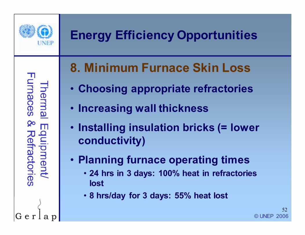
• Choosing appropriate refractories
• Increasing wall thickness
• Installing insulation bricks (= lower
conductivity)
• Planning furnace operating times
• 24 hrs in 3 days: 100% heat in refractories
lost
• 8 hrs/day for 3 days: 55% heat lost
8. Minimum Furnace Skin Loss

© UNEP 2006
53
Energy Efficiency Opportunities
• High emissivity coatings
• Long life at temp up to 1350 oC
• Most important benefits
• Rapid efficient heat transfer
• Uniform heating and extended refractory life
• Emissivity stays constant
• Energy savings: 8 – 20%
9. Use of Ceramic Coatings

© UNEP 2006
54
Energy Efficiency Opportunities
Selection criteria
• Type of furnace
• Type of metal charge
• Presence of slag
• Area of application
• Working temperatures
• Extent of abrasion
and impact
10. Selecting the Right Refractory
• Structural load of
furnace
• Stress due to temp
gradient & fluctuations
• Chemical compatibility
• Heat transfer & fuel
conservation
• Costs

© UNEP 2006
55
Training Session on Energy
Equipment
Furnaces and
Refractories
THANK YOU
FOR YOUR ATTENTION
�
© UNEP 2006
56
Disclaimers and References
• This PowerPoint training session was prepared as part of
the project “Greenhouse Gas Emission Reduction from
Industry in Asia and the Pacific” (GERIAP). While
reasonable efforts have been made to ensure that the
contents of this publication are factually correct and
properly referenced, UNEP does not accept responsibility for
the accuracy or completeness of the contents, and shall not
be liable for any loss or damage that may be occasioned
directly or indirectly through the use of, or reliance on, the
contents of this publication. © UNEP, 2006.
• The GERIAP project was funded by the Swedish
International Development Cooperation Agency (Sida)
• Full references are included in the textbook chapter that is
available on www.energyefficiencyasia.org